Cadence Design Systems, Inc. Why Interconnect Prediction Doesn’t Work.
30
Cadence Design Systems, Inc. Why Interconnect Prediction Doesn’t Work
-
Upload
kayley-dutton -
Category
Documents
-
view
223 -
download
0
Transcript of Cadence Design Systems, Inc. Why Interconnect Prediction Doesn’t Work.
Cadence Design Systems, Inc.
Why Interconnect Prediction Doesn’t Work

2
conf
iden
tial
IntroductionHow is interconnect planning used in industry today?Problems with interconnect prediction
– What limits the accuracy?– Can it be improved?
Alternatives to interconnect predictionThe future of interconnect prediction

3
conf
iden
tial
Interconnect Prediction little used in industry
Examples of interconnect prediction– Wire load models – used in synthesis– Rent’s rule – used in sizing FPGAs and Gate Arrays
But wire load models are being replaced by Physical Synthesis– Tools with constructive prediction sell for 4-10x same tool with
wire load models.– Main reason – reliability of results
Rent’s rule replaced by extensive experimentation
4
conf
iden
tial
Problems with Interconnect EstimationThe law of small numbersCollective effects, or the N-1 problemAll layers are not created equal The devil is in the details
5
conf
iden
tial
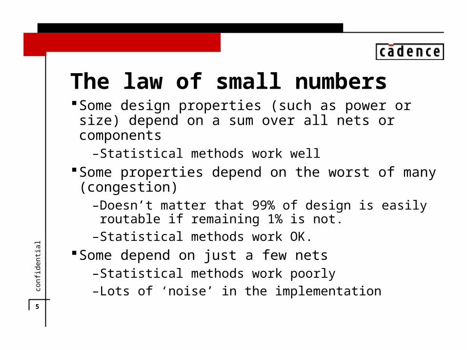
The law of small numbersSome design properties (such as power or size) depend on a
sum over all nets or components– Statistical methods work well
Some properties depend on the worst of many (congestion)– Doesn’t matter that 99% of design is easily routable if remaining
1% is not.– Statistical methods work OK.
Some depend on just a few nets– Statistical methods work poorly– Lots of ‘noise’ in the implementation

6
conf
iden
tial
Law of small numbers example Imagine a 30%, normally distributed, uncorrelated error per net Imagine estimation is perfectly calibratedThen we would expect
– A sum property off by 0.03%– A max property off by 7-8% for N=100K-1M
– (order statistics)– An individual net off by 30%

7
conf
iden
tial
Law of small numbers
Timing is one of the most critical predictionsTiming may depend on only a small subset of nets
– 128 bit adder has about 4K paths through it, but only one is critical.
Number of nets that are critical varies wildly from design to design.

8
conf
iden
tial
Slack by net for two designs
0
500
1000
1500
2000
2500
3000
3500
-5 0 5 10 15 20
Slack Relative to Worst Net (ns)
Nu
mb
er
of
Ne
ts
Series1
Series2

9
conf
iden
tial
Collective Effects, or the N-1 problem
Effects that cannot be predicted one nets at a time.
N netsN-1 space
1 net

10
conf
iden
tial
All layers are not created equal
Layers differ in:– Pitch– Performance– Effects on other layers (via blockage)
Assignment based on timing, not routabilityLots of design to design variation
11
conf
iden
tial
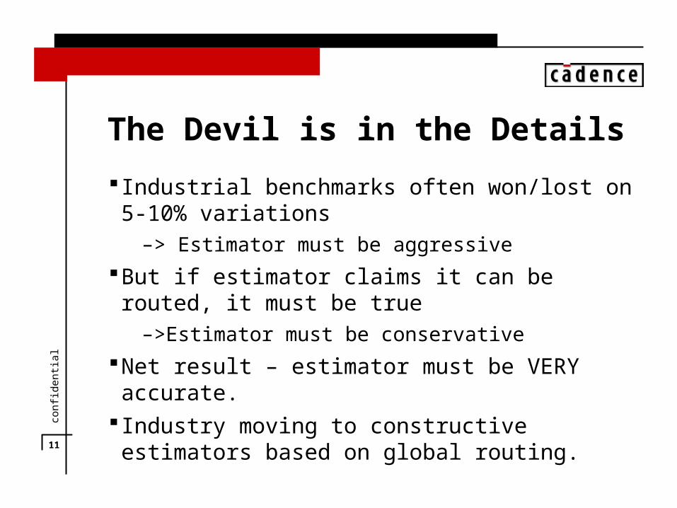
The Devil is in the Details
Industrial benchmarks often won/lost on 5-10% variations– > Estimator must be aggressive
But if estimator claims it can be routed, it must be true– >Estimator must be conservative
Net result – estimator must be VERY accurate. Industry moving to constructive estimators based on global
routing.

12
conf
iden
tial
Details that make a difference
Wrong way routingPin blockagesAntenna rulesVia blockageTiming driven routing

13
conf
iden
tial
Wrong way routing
Modern routers can route in the ‘wrong’ direction– Locally, to relieve congestion– Over a whole ‘channel’, to fix pin access issues
Confuses estimatorsCan route over capacity
14
conf
iden
tial
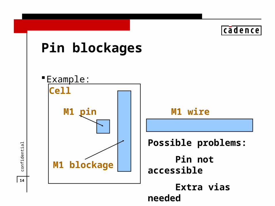
Pin blockages
Example:
M1 pin
M1 blockage
M1 wire
Possible problems:
Pin not accessible
Extra vias needed
Cell

15
conf
iden
tial
Antenna Rules
A long line connected to gate only can cause failureNot a problem after chip is complete since every net has at least
one driver
Driver (diffusion) Load (poly)
M1
M2

16
conf
iden
tial
Antenna Rules
But, we can have a problem during manufacturingHere is the same net after M1 is built, but not yet M2Error!
Driver (diffusion) Load (poly)
M1

17
conf
iden
tial
Antenna Rules
Possible solution – reverse order of layer assignmentsChanges local layer utilization
Driver (diffusion) Load (poly)
M1
M2

18
conf
iden
tial
Antenna Rules
After M1 is built…. OK so far
Driver (diffusion) Load (poly)
M1
M2

19
conf
iden
tial
Antenna Rules
After M2 is built
Driver (diffusion) Load (poly)
M1
M2

20
conf
iden
tial
Antenna Rules
Another possible solutionLittle change of routing, but adds vias
Driver (diffusion) Load (poly)
M1
M2
21
conf
iden
tial
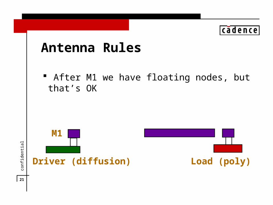
Antenna Rules
After M1 we have floating nodes, but that’s OK
Driver (diffusion) Load (poly)
M1
22
conf
iden
tial
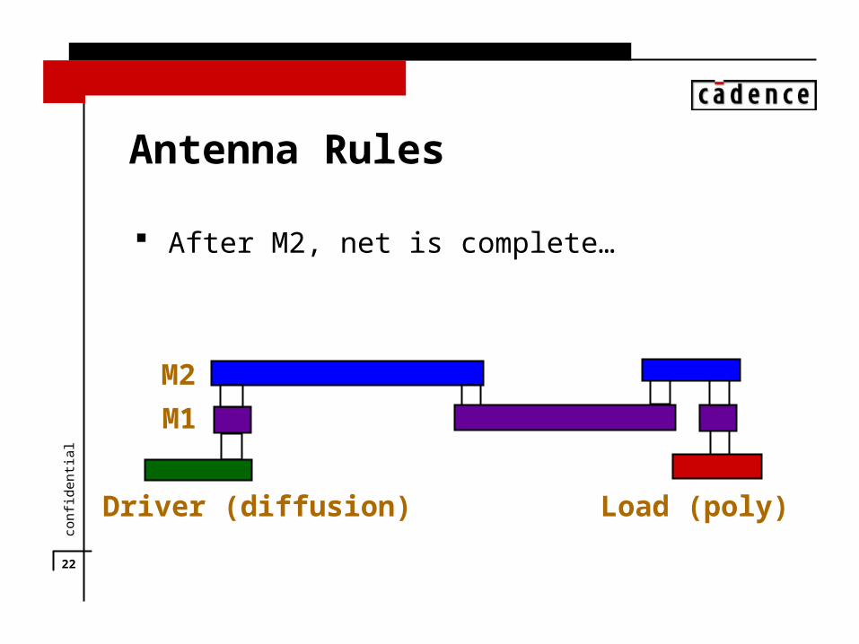
Antenna Rules
After M2, net is complete…
Driver (diffusion) Load (poly)
M1
M2

23
conf
iden
tial
Antenna Rules
Another solution – add diodes In practice, required by modern rulesBut introduces more via blockage (and performance penalty)
Driver (diffusion) Load (poly)
M1
M2

24
conf
iden
tial
Via blockage
Each upper layer route requires at least two vias on each layer below.
Natural strategy – route longest net on topmost layer to reduce via blockages.
– But layer assignments based on timing, not via blockage– Timing varies considerably from design to design

25
conf
iden
tial
Can the estimators be upgraded?
Need to add placement informationNeed to do layer assignmentNeed to generate Steiner routes respecting capacitiesNeed to look at ‘relevent’ routing detailsNeed final router to follow previous decisionsBut this is exactly a global router!

26
conf
iden
tial
Results of two estimators
27
conf
iden
tial
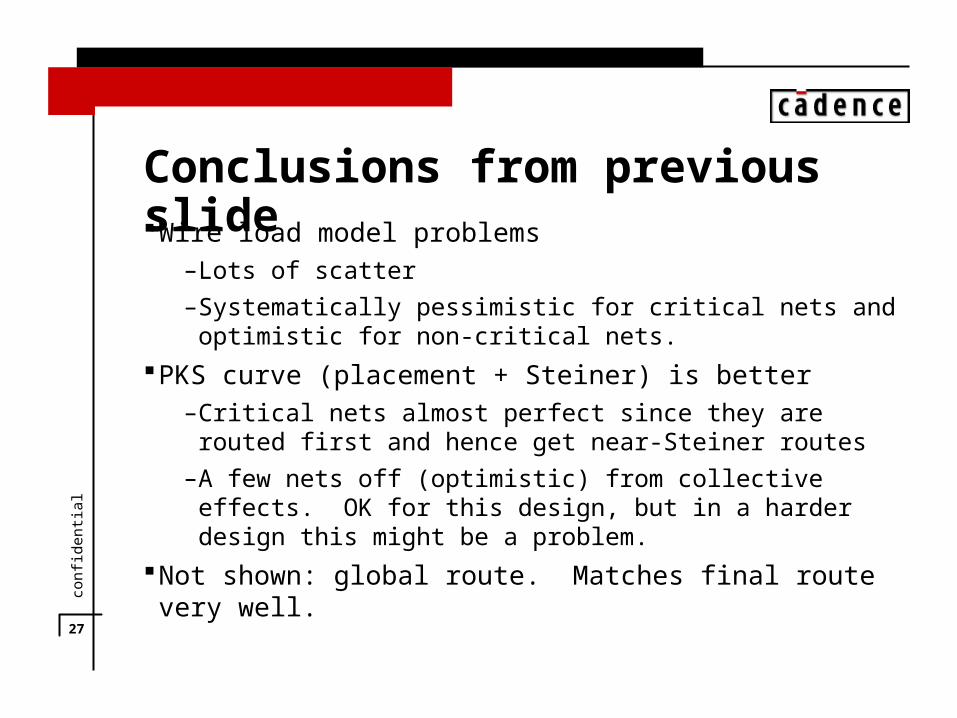
Conclusions from previous slideWire load model problems
– Lots of scatter– Systematically pessimistic for critical nets and optimistic for non-
critical nets.PKS curve (placement + Steiner) is better
– Critical nets almost perfect since they are routed first and hence get near-Steiner routes
– A few nets off (optimistic) from collective effects. OK for this design, but in a harder design this might be a problem.
Not shown: global route. Matches final route very well.
28
conf
iden
tial
FPGA and Gate Array Design
Traditional use for Interconnect PredictionNow moving towards extensive trials. Why?
– Running previous generation detail router, or a crude global router tuned to the new architecture, give better results than predictors
– Customers have expectations not related to wiring models. For example, certain data path elements MUST be wireable.
– Small details (which side a pin is on) make big differences

29
conf
iden
tial
What are people doing instead?
Methodology changes:– Do global routing first
– Used by microprocessor companies internally– NANO project from Cadence
Tool changes– Combine synthesis & placement (better)– Combine synthesis, placement & global route (better yet)– Possible extensions – add detailed route, clock tree, test insertion,
etc.

30
conf
iden
tial
Future of Interconnect predictionWhere is interconnect prediction useful?Prediction of radical process changes for which no detailed tools
exist:– 3D interconnect– Optical interconnect– Wild new FPGA architectures
Properties that really do depend on averages– Yield analysis