CADD Specification Manual - City of Toronto 11 Version 1.3 Upgrade Notes 11 Surrounds 11 Levels ...
78
D&C-LI Technical Services City of Toronto Version 1.3 CADD Specification Manual
Transcript of CADD Specification Manual - City of Toronto 11 Version 1.3 Upgrade Notes 11 Surrounds 11 Levels ...

D&C-LI
Technical Services
City of Toronto
Version 1.3
CADD Specification Manual


Design & Construction – Linear Infrastructure
CADD Specification Manual Version 1.3
September 2012

The Design & Construction – Linear Infrastructure CADD Specification Manual (Version 1.3) has been prepared by Data Integration Services, Technical Services, City of Toronto. For errors and/or omissions, please contact Data Integration Services. For contact information, please view the "City CADD Contacts" section of this manual.

Table of Contents
September 2011 5
Table of Contents
Introduction ................................................................................................... 11
Version 1.3 Upgrade Notes ........................................................... 11
Surrounds .......................................................................... 11
Levels ......................................................................................... 12
Cells ............................................................................................ 12
Task Manager & On-line Help File ............................................. 13
What This Manual Contains .......................................................... 13
Chapter 1 — Drawing Setup ................................................... 15
Recommended Software .............................................................. 15
Seed File ........................................................................................ 16
Global Origin ........................................................................................... 16
Working Units ............................................................................ 16
Mapping Co-ordinates .................................................................. 17
Drawing Scale ................................................................................ 18
Linear Design Work ................................................................................. 18
Structures and Expressways Design Work ................................. 18
Level Structure .............................................................................. 19
New Drawing ................................................................................. 20
DGN Library (dgnlib) ............................................................................... 20
Resource File (rsc) ...................................................................... 21
Colour Table File (ctb) ................................................................ 21
Making Resources Available ...................................................... 21
Chapter 2— Project Setup ................................................................ 23
Folder Structure ............................................................................ 23

D&C-LI CADD Specification Manual (Version 1.3)
6 September 2012
CADD File Type .............................................................................. 25
Master File .......................................................................... 25
Master File Name Change .................................................... 26
Master File Name Change – Linear........................................ 26
Master File Name Change – Structures and Expressways ....... 28
Reference File ................................................................... 29
Cover Sheet ......................................................................... 33
Base Plan Data .............................................................................. 34
CADD File Naming Convention ..................................................... 34
File Renaming ...................................................................... 34
Chapter 3— Title Block and Revisions ........................................... 35
Title Block ...................................................................................... 35
Main Information .............................................................. 35
Date ................................................................................... 36
Drawing Number ................................................................. 37
Scale – Linear Design Work .................................................. 37
Scale – Structures and Expressways Design Work .................. 38
Design, Drawn and Checked ................................................. 39
Contract Number ................................................................. 39
Sheet ................................................................................. 40
Professional Seals ................................................................ 41
Engineering Consultant's Information and Disclaimer ............ 41
Revisions ....................................................................................... 42
Revision Notes .................................................................... 42
Chapter 4— Drawing and Plotting ................................................. 43
Drawing ......................................................................................... 43
Task Manager ...................................................................... 43
Table of Contents
September 2011 7
Cells and Cell Libraries ......................................................... 44
Orientation ......................................................................... 45
Scale .................................................................................. 46
Line Weight ......................................................................... 47
Line Styles ........................................................................... 48
Patterns and Hatching ......................................................... 48
Text Style and Size ............................................................... 49
Drafting Abbreviations ......................................................... 49
Match Lines......................................................................... 49
Key Plan .............................................................................. 49
Leader Lines ........................................................................ 50
Multi-Lines .......................................................................... 50
Dimensions ......................................................................... 51
InRoads .......................................................................................... 52
Specification Checker .................................................................... 53
Plotting .......................................................................................... 54
Sheet Size ........................................................................... 54
Drawing Path and File Name ................................................ 54
Plot Material ....................................................................... 55
Master File Plot ................................................................... 55
Chapter 5— Procedures for Consultants ...................................... 57
Data Format and Conversion ........................................................ 57
Data Transfer — Data Outgoing from the City ............................. 57
Design & Construction – Linear Infrastructure Disclaimer ....... 58
Digital Data Submitted to the City ................................................ 58
Submission Review .............................................................. 59
Plotting of Drawings ............................................................ 59

D&C-LI CADD Specification Manual (Version 1.3)
8 September 2012
Appendix A— Digital CADD Data Disclaimer ............................... 61
Appendix B— Digital File Submission Form ................................ 64
Appendix C— Bentley MicroStation Resources ......................... 65
Appendix D— Additional Documentation ................................... 67
Appendix E— City CADD Contacts .................................................. 69
Glossary .................................................................................................. 73

Table of Contents
September 2011 9
List of Tables
Table Description Page 1 MicroStation Seed Files 14 2 MicroStation Working Units 14 3 City of Toronto Co-ordinate System 15 4 DGN Libraries (DGNLIBs) 18 5 Resource Files (rsc) 19 6 Colour Table File (ctb) 19 7 Delivered (Preliminary) Master File Name Syntax 24 8 Linear Design Master File Name Change for Tender 25 9 Master File Names for Linear Design Work 25
10 Structures & Expressways Design Master File Name Change for Tender 26 11 Master File Names for Structures & Expressways Design Work 26 12 DESIGN (Proposed) Reference Files 28 13 INROADS (Proposed) Reference Files 29 14 PROPERTY LINE (Existing) Reference Files 30 15 TOPOGRAPHIC (Existing) Reference Files 30 16 UTILITIES (Existing) Reference Files 31 17 MISCELLANEOUS Reference Files 31 18 Revision Notes Fields 40 19 Cell DGN Libraries 42 20 MicroStation Line Weight to Metric Width Chart 45 21 Line Style Resource Files 46 22 Required InRoads Files 50 23 Files Required for Specification Checker 51 24 Files Available for Iplot Plotting Environment 52 25 Recommended Line Weights when Plotted in Full Size 53 26 MicroStation File Locations 63 27 Available Additional Documentation for Version 1.2 65 28 District Design/CADD/Plans Administration Supervisors 67 29 Contact for CADD Documentation 67 30 Contact for TIMS Administration 68 31 Contact for Utility Mapping (DMOG and CUMAP) 68 32 Contact for Parcel Mapping 68 33 Contact for Engineering Survey Operations 68 34 Contact for Engineering Survey Graphic Specification 68 35 Contact for Topographic (ESM) Mapping 69 36 Contact for Trunk Sewers and Transmission Watermains 69 37 Contact for Transportation Services 69
D&C-LI CADD Specification Manual (Version 1.3)
10 September 2012
List of Figures
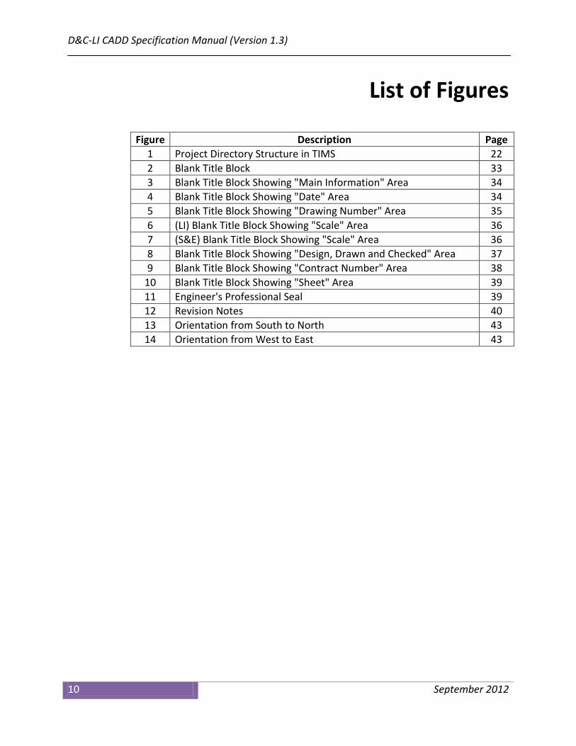
Figure Description Page 1 Project Directory Structure in TIMS 22 2 Blank Title Block 33 3 Blank Title Block Showing "Main Information" Area 34 4 Blank Title Block Showing "Date" Area 34 5 Blank Title Block Showing "Drawing Number" Area 35 6 (LI) Blank Title Block Showing "Scale" Area 36 7 (S&E) Blank Title Block Showing "Scale" Area 36 8 Blank Title Block Showing "Design, Drawn and Checked" Area 37 9 Blank Title Block Showing "Contract Number" Area 38
10 Blank Title Block Showing "Sheet" Area 39 11 Engineer's Professional Seal 39 12 Revision Notes 40 13 Orientation from South to North 43 14 Orientation from West to East 43

Introduction
September 2012 11
Introduction
The D&C-LI CADD Specification Manual has been prepared to assist City of Toronto Design and Construction – Linear Infrastructure (D&C-LI) staff along with consulting engineers retained by the City of Toronto when creating engineering drawings for capital projects in the Technical Services division. This manual gives a general overview of the Design and Construction – Linear Infrastructure CADD drawing standards and specifications you will need when preparing any engineering drawing. Additional reference documents are available and will be noted, where applicable.
Version 1.3 Upgrade Notes
The following changes have been made to the Design and Construction – Linear Infrastructure (D&C-LI) CADD drawing standards and specifications for the release of Version 1.3: Surrounds • All drawing "surrounds" have been recreated at a scale of 1:1 to
match drawing "surrounds" used by Design and Construction – Major Works Facilities. A scale factor of "200" is applied for "surround" placement when using "Task Manager" to ensure that the final drawing scale is 1:200.
• New "surround" levels were created to fix some issues when
"surround" cells were dropped. All "surround" levels are now "by-level".
• All "Executive Director", "Director" and "Manager" names have been
removed from drawing "surrounds". Nine (9) cells (models) have been created with the appropriate names. The appropriate name(s) can be selected through "Task Manager".

D&C-LI CADD Specification Manual (Version 1.3)
12 September 2012
Levels • The level structure for the "Structures and Expressways" component
of the specification for bridge work was updated. The changes are listed in the table below:
Table I: Changes to "Structures & Expressways" Levels
Level Name Change Hidden_Linework_A_DES New Hidden_Linework_B_DES New Hidden_Linework_C_DES New Hidden_Linework_D_DES New Hidden_Linework_E_DES New Bridge_Cable_Proposed_DES Weight = 5 Bridge_CL_Existing_DES Line Style = 4 Bridge_CL_Proposed_DES Line Style = V8 centre
Weight = 1 Bridge_Dimension_Proposed_DES Weight = 1 ; Colour = 0 Bridge_Hatching_Proposed_DES Weight = 2 Bridge_Rebar_Existing_DES Line Style = 2 Bridge_Rebar_Proposed_DES Weight = 5 Bridge_Structural_Joints_Existing_DES Line Style = 2 Bridge_Structural_Joints_Proposed_DES Line Style = 2 Bridge_Title_Symbology_Proposed_DES Weight = 3 Bridge_Notes_Proposed_DES Deleted Cells • Certain "legend" and "note" cells have been recreated to ensure that
when the cell is "dropped", all resulting levels are "by-level".
• Thirteen (13) new cells were created to deal with section "titles/notes" primarily for, but not limited to, "Structures and Expressways" bridge work. All cells were created at a scale of 1:1 and added to "Task Manager" under the "TEXT / SECTION NOTES" tab. The new cells are:
1. sectno 2. sectno1 3. sectno2 4. sectno3 5. sectno4 6. sectno5

Introduction
September 2012 13
7. sectno6 8. sectno7 9. sectno8 10. sectno9 11. sectno10 12. sectno11 13. sectno12
Task Manager & On-line Help File • Four (4) videos have been added to the help file accessed through
"Task Manger" and all associated documentation has been updated to reflect changes to the specification. The on-line help file, "Help.pdf" has been updated to include bookmarks to provide an index of available topics.
• Certain commands in "Task Manager" were placing elements with an
attribute override resulting in "by-level" errors. This issue has been fixed.
• "Existing" utility labels and "existing" crossing utility labels have been
moved to the appropriate discipline tabs. Specifically, "Storm", "Sanitary", "Combined", "Watermain" and "Gas" have now been moved to their respective tab.
• Discipline related text (i.e. "Storm", "Sanitary", "Combined",
"Watermain", etc.) has been moved out of the "Text" tab and placed in the appropriate utility text tab.
• Some task descriptions have been modified to provide description
consistency. Some tasks were missing the word "existing" or "proposed".
What This Manual Contains
Chapter 1 – Drawing Setup This chapter covers drawing setup and settings for mapping co-ordinates, global origin, working units, drawing scale, level structure and DGNLIBs.

D&C-LI CADD Specification Manual (Version 1.3)
14 September 2012
Chapter 2 – Project Setup This chapter covers project setup (using the TIMS hierarchy), CADD file types, and CADD file naming conventions. Chapter 3 – Title Blocks and Revision Notes This chapter covers title blocks, consultant information and disclaimers, professional seals and drawing revision notes. Chapter 4 – Drawing and Plotting This chapter covers aspects of drawing and plotting CADD files. Chapter 5 – Procedures for Consultants This chapter covers the data transfer of outgoing files from the City, data incoming from consulting engineers, submission review and plotting of drawings. Appendix A – Digital CADD Data Disclaimer This appendix contains the standard digital data disclaimer notice regarding information supplied by the City. Appendix B – Digital File Submission Form This appendix contains the standard digital file submission form which must be completed and submitted with any corresponding digital files. Appendix C – Bentley MicroStation Resources This appendix contains a list of MicroStation resources and other files required for this version of the CADD specification. Appendix D − Additional Documentation This appendix contains a list of additional documents (some referred to in this manual) that may provide more information about the CADD specification and standards. Appendix E – Digital CADD Contacts This appendix gives a list of contacts in the City for specific issues dealing with the CADD specification. Glossary An alphabetical list of technical terms used in this manual relating to computer aided design and drafting and their definitions.

Chapter 1 — Drawing Setup
September 2012 15
Chapter 1 Drawing Setup
Computer aided design and drafting (CADD) data produced by the Design & Construction – Linear Infrastructure section in the Technical Services division is subject to the standards, specifications and procedures as detailed in this manual. Additional documents mentioned should be used to supplement the information contained in this manual. The Technical Services division creates and maintains CADD data in Bentley MicroStation design file (.dgn) format. Data files are provided and exchanged using the MicroStation version 8 (V8) file format. Data originating from outside parties, such as contractors and suppliers, will be made available in its original format, without data conversion. All CADD files provided to consulting engineers by the Design & Construction – Linear Infrastructure section use the "Pack and Go" utility (WinZip) in the Technical Information Management System (TIMS) software.
Recommended Software
The following software is utilized by staff in the Technical Services division for their day to day operations: • Microsoft™ XP Professional Service Pack 3 • Microsoft™ Office XP 2007 (or better) • Bentley™ MicroStation 8i (version 08.11.xx) • Bentley™ InRoads 8i (version 08.11.xx) • Bentley™ ProjectWise InterPlot Organizer (version 08.11.xx) • Bentley™ ProjectWise InterPlot Server (version 08.11.xx) • Adobe PDF Reader Version 6 (or better)

D&C-LI CADD Specification Manual (Version 1.3)
16 September 2012
Seed File
All CADD files are created using City standard MicroStation seed files. These seed file are provided as part of the CADD information package. For more information on this package, see "Chapter 5, Procedures for Consultants" of this manual. There are two (2) seed files available and they are listed in the following table. Table 1: MicroStation Seed Files Seed File Name Usage v8_seed_2d_1.3.dgn 2D design work v8_seed_3d_1.3.dgn 3D design work
Global Origin The global origin (GO) is a point in space indicating the origin of the Cartesian co-ordinate system used in design plane co-ordinates. All CADD files use a standard global origin in the seed file of x = 0 and y = 0 for 2D files and x = 0, y = 0 and z = 0 for 3D files. This places the origin (0,0) of the design plane in the bottom left corner making all co-ordinates in the design plane positive. A change to the global origin is not permitted. Working Units All CADD files have units of resolution as per the City standard seed files. The table below shows the settings for working units in the seed files. A change to the units of resolution is not permitted. Table 2: MicroStation Working Units Setting Value Master Unit Meters (m) Sub Unit Centimeters (cm) Format MU (master units) Resolution 2500 units per meter

Chapter 1 — Drawing Setup
September 2012 17
Mapping Co-ordinates
The City of Toronto's operational co-ordinate system is the 3-degree Modified Transverse Mercator (MTM), Ontario Zone 10, North American Datum 1927 (NAD27). All CADD files are drawn using this co-ordinate system. The X and Y co-ordinates are related to real world grid co-ordinates. Within the geographic vicinity of the City of Toronto, metric co-ordinate values are in the range ±4,800,000 metres (northing) along the Y-axis and ±300,000 metres (easting) along the X-axis. City base mapping and subsequent reference files are co-ordinated to this grid system (3° MTM). All CADD files, when referenced together, shall represent the final work in its entirety. Table 3: City of Toronto Co-ordinate System Setting Value Datum North American Datum 1927 (NAD27) Projection 3° Modified Transverse Mercator (MTM) Zone 10

D&C-LI CADD Specification Manual (Version 1.3)
18 September 2012
Drawing Scale
Linear Design Work All CADD files should be drawn to scale using metric units. Design files are drawn exclusively to a scale of 1:1. Master design files are plotted at a scale of 1:200. Available surrounds are preset at 1:1 and must be scaled to plot at 1:200. Commands in "Task Manger" are available to perform this scaling. The number of master files is dependent on the length and shape of the contract area. Structures and Expressways Design Work All CADD files should be drawn to scale using metric units. Certain areas and/or features may be shown as a "detail" with exaggerated scale. Reference files may be scaled at attachment. The scale must be clearly noted for the particular "detail" or reference file if not at the same scale as the final plot. Master design files are plotted at a scale of 1:1. The available surround is preset to plot to 1:1. All general arrangements should be reference scaled and plotted at the same scale, as dictated by the City project manager. The number of master files is dependent on the complexity of the project.

Chapter 1 — Drawing Setup
September 2012 19
Level Structure
Levels (or layers) are used to separate various types of data. All elements in the design (drawing) files must be placed on their own pre-assigned level(s). Technical Services uses a "by-level" approach in the level structure. Each level is assigned a unique symbology (colour, weight, line style, etc.) that must be adhered to. The level structure is stored in the V8_Levels_1.3.dgnlib DGN library (DGNLIB). Attaching DGN libraries (DGNLIBs) is described in the next section, "New Drawing, Making Resources Available", of this manual. All files in the project must adhere to the same level structure. Changes to the level structure are not permitted.
Additional Documentation For more information about the D&C-LI level structure, please refer to the Design & Construction Linear Infrastructure – Version 1.3 MicroStation Levels reference document. Each level in the Version 1.3 graphic specification is documented with the following information:
• Level Name • Level Number • Level Description • Level Line Style (by-level) • Level Weight (by-level) • Level Colour Number (by-level) • Level RGB Colour Value
See "Appendix D, Additional Documentation" for document file name.

D&C-LI CADD Specification Manual (Version 1.3)
20 September 2012
New Drawing
All resources required for new drawings are contained in various files, with three (3) main file types:
1. dgnlib (DGN library) 2. rsc (resource file) 3. ctb (colour table file)
DGN Library (dgnlib) The DGN library, or dgnlib, is a special design file that contains data that is shared throughout files and among users. These shared resources consist of things that you define and name, which are used as standards by members of a workgroup. In general, the following data is stored in the supplied dgnlibs: • level definitions • cell definitions • multi-line settings • dimension settings • text settings The following table lists the dgnlibs required for Version 1.3. Table 4: DGN Libraries (DGNLIBs) DGN LIBRARY CONTAINS V8_levels_1.3.dgnlib levels ; multi-line settings ; dimension
settings ; text settings ; tasks This is the main dgnlib.
V8_cells_master_1.3.dgnlib cell models ; patterning models ; terminators
V8_cells200_1.3.dgnlib miscellaneous models V8_flags_1.3.dgnlib models for InRoads resources V8_surrounds_1.3.dgnlib surrounds ; cover pages ; surround
features V8_utilities_1.3.dgnlib utility models ; existing & proposed in
plan & profile
The modification of any resource files is not permitted.

Chapter 1 — Drawing Setup
September 2012 21
Table 4: DGN Libraries (DGNLIBs) (continued) DGN LIBRARY CONTAINS V8_wfittings_1.3.dgnlib watermain fittings in plan & profile Resource File (rsc) The resource files, supplied with this version, contain various custom (user defined) line styles and fonts. The following table lists the resource files required for this version. Table 5: Resource Files (rsc) RESOURCE FILE CONTAINS svylstyl_1.3.rsc engineering survey line styles esm_udls_1.3.rsc topographic mapping line styles englstyl_1.3.rsc engineering line styles (compatibility) acadlstyl_1.3.rsc AutoCAD line styles v8_custom_linestyles_1.3.rsc D&C-LI line styles xfont_1.3.rsc fonts Colour Table File (ctb) The colour table file defines the colours associated with the levels. The following table lists the colour table file. Table 6: Colour Table File (ctb) COLOUR TABLE FILE CONTAINS engcolor_1.3.ctb engineering colour table Making Resources Available All resources should be attached (made available) through a "WorkSpace" defined in MicroStation. A user configuration file (ucf) should be used to load resource files that are required for the particular "WorkSpace". A user configuration file (ucf) for this version, v8_dcli_1.3.ucf, is provided as part of the information package provided on the CD.

D&C-LI CADD Specification Manual (Version 1.3)
22 September 2012

Chapter 2 — Project Setup
September 2012 23
Chapter 2 Project Setup
Folder Structure
Project folders identify storage areas common for all project files. The folder structure may also be used to apply security to a single or group of files (drawings).
Project folders are created automatically using WinZip to unpack files created by the "Pack and Go" utility in the Technical Information Management System (TIMS) software. WinZip extraction should point to the root directory (c:\) for folders and files to be extracted.
Files are to remain in the originating directories and referenced into the master file. Reference files should be attached with the "Save Relative Path" check box checked in the "Attach Reference" form (the check box is near the bottom of the form).
The next figure shows a TIMS screen capture of a project directory structure.

D&C-LI CADD Specification Manual (Version 1.3)
24 September 2012
Figure 1: Project Directory Structure in TIMS
Additional Documentation For more information about TIMS, please refer to the following reference documents:
• TIMS Overview – City Data Manager • TIMS Structure and Attribution • TIMS Indexing Protocols • TIMS Attributing for As-Builts
See "Appendix D, Additional Documentation" for document file names.

Chapter 2 — Project Setup
September 2012 25
CADD File Type
Master file and reference file are the two (2) CADD file types used for linear design work and structures and expressways work. There are some differences between linear design work and structures and expressways work in terms of the master and reference files. These differences will be noted when required. Master File A master file contains a surround title block, legend, north arrow and key map. The project street name or structure and limits with applicable information about the project must be included in the title block. All graphic data for the project area will be drawn in real size that is at a scale of 1:1. Design work will be completed in separate MicroStation design files and referenced into the master file. Reference scaling may be required for structures and expressways work. At no time should any of these files be merged. The consulting engineer will be provided with one master MicroStation design file for each project. For example — y11254u1.dgn. Additional copies of this design file will have to be created depending on the length, complexity and/or layout of each particular project. Sequential numbers are used for this purpose. For example — y11254u2.dgn ; y11254u3.dgn ; y11254u4.dgn ; etc. Only D&C-LI staff is authorized to create original master file drawing numbers. Preliminary file names are a combination of year of project, project number, work type and sequential number (as discussed above). Both linear design work and structures and expressways design work use the same syntax for preliminary master file names. The table on the next page gives an example of this file naming syntax for delivered preliminary master files.
D&C-LI CADD Specification Manual (Version 1.3)
26 September 2012
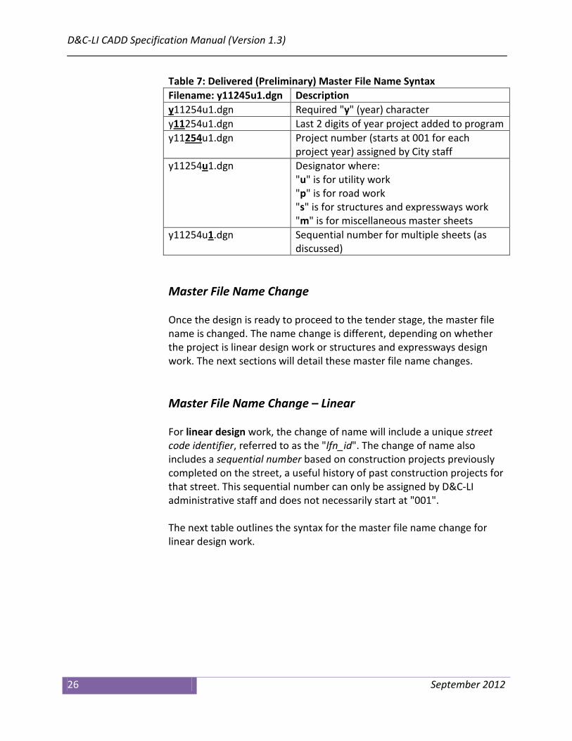
Table 7: Delivered (Preliminary) Master File Name Syntax Filename: y11245u1.dgn Description y11254u1.dgn Required "y" (year) character y11 Last 2 digits of year project added to program 254u1.dgn y11254 Project number (starts at 001 for each
project year) assigned by City staff u1.dgn
y11254u1.dgn Designator where: "u" is for utility work "p" is for road work "s" is for structures and expressways work "m" is for miscellaneous master sheets
y11254u1.dgn Sequential number for multiple sheets (as discussed)
Master File Name Change Once the design is ready to proceed to the tender stage, the master file name is changed. The name change is different, depending on whether the project is linear design work or structures and expressways design work. The next sections will detail these master file name changes. Master File Name Change – Linear For linear design work, the change of name will include a unique street code identifier, referred to as the "lfn_id". The change of name also includes a sequential number based on construction projects previously completed on the street, a useful history of past construction projects for that street. This sequential number can only be assigned by D&C-LI administrative staff and does not necessarily start at "001". The next table outlines the syntax for the master file name change for linear design work.

Chapter 2 — Project Setup
September 2012 27
Table 8: Linear Design Master File Name Change for Tender Filename: U-6907-001.dgn Description U-6907-001.dgn Designator where:
"U" is for utility work "P" is for road work "M" is for miscellaneous master sheets
U-6907-001.dgn Dash "-" separator character between designator and "lfn_id"
U-6907 "lfn_id" (unique street code identifier) for -001.dgn Tinder Crescent
U-6907-001.dgn Dash "-" separator character between "lfn_id" and sequential number
U-6907-001 Next available sequential number for projects on this street, assigned by authorized D&C-LI staff
.dgn
The following table shows examples of master file naming at both the preliminary and tender stage for linear design work. Table 9: Master Files Names for Linear Design Work Filename Example Description <job#>p?.dgn y11254p1.dgn
y11254p2.dgn Preliminary (pre-tender) master file name for road work. (?=sequential number)
P-lfn_id-???.dgn P-6907-001.dgn P-6907-002.dgn
Final contract master file name for road work. (???=sequential number)
<job#>u?.dgn y11254u1.dgn y11254u2.dgn
Preliminary (pre-tender) master file name for utility work. (?=sequential number)
U-lfn_id-???.dgn U-6907-001.dgn U-6907-002.dgn
Final contract master file name for utility work. (???=sequential number)
<job#>m?.dgn y11254m1.dgn y11254m2.dgn
Preliminary (pre-tender) master file name for miscellaneous master sheets. (?=sequential number)
M-lfn_id-???.dgn M-6907-001.dgn M-6907-002.dgn
Final contract master file name for miscellaneous master sheets. (???=sequential number)

D&C-LI CADD Specification Manual (Version 1.3)
28 September 2012
Master File Name Change – Structures and Expressways For structures and expressways design work, the name change will include a unique structural identifier and a unique bridge number. A sequential number, similar to that for linear design work, is also part of the name change. The next table outlines the syntax for the master file name change. Table 10: Structures & Expressways Design Master File Name Change for Tender Filename: 123-S-456-001.dgn Description 123 Structural identifier -S-456-001.dgn 123-S-456-001.dgn Dash "-" separator character between
structural identifier and designator 123-S-456-001.dgn Designator where:
"S" is for structures and expressways work
123-S-456-001.dgn Dash "-" separator character between designator and bridge number
123-S-456 Bridge number -001.dgn 123-S-456-001.dgn Dash "-" separator character between
bridge number and sequential number 123-S-456-001 Next available sequential number,
assigned by authorized D&C-LI staff .dgn
The following table shows examples of master file naming at both the preliminary and tender stage for structures and expressways design work. Table 11: Master File Names for Structures & Expressways Design Work Filename Example Description <job#>s?.dgn y11254s1.dgn
y11254s2.dgn Preliminary (pre-tender) master file name for structures and expressways work. (?=sequential number)
si-S-bn-???.dgn 123-S-456-001.dgn 123-S-456-002.dgn
Final contract master file name for structures and expressways work. (si=structural identifier) (bn= bridge number) (???=sequential number)

Chapter 2 — Project Setup
September 2012 29
Reference File Generally, there is only one (1) reference file from the various types for each project, regardless of the number of master files required. When attached to a master file, the required area in the reference file will be visible based on the location of the master file. The naming convention for reference files is indicated in the following tables. Tables are broken into the following categories: • Design (proposed features) reference files • InRoads (proposed features) reference files • Property line (existing features) reference files • Topographic (existing features) reference files • Utilities (existing features) reference files • Miscellaneous reference files Reference files listed in the following tables are valid for both linear design work and structures and expressways design work. The "Logical Name" column in the tables contains the logical name that should be used when design files are attached as references to the master file(s). In the tables on the following pages, an example file name is given, based on the job number (<job#>) from the previous section, namely "y11254".

D&C-LI CADD Specification Manual (Version 1.3)
30 September 2012
Table 12: DESIGN (Proposed) Reference Files General File Name Logical
Name Description & Example File Name
<job#>arch.dgn arch Architectural design for structural work. Example: y11254arch.dgn
<job#>comb.dgn comb Combined sewer design (plan view). Example: y11254comb.dgn
<job#>combda.dgn combda Combined sewer drainage areas design (plan view). Example: y11254combda.dgn
<job#>combpf.dgn combpf Combined sewer design profile. Example: y11254combpf.dgn
<job#>det.dgn det Details and sections. Example: y11254det.dgn
<job#>elec.dgn elec Electrical design for structural work (plan view). Example: y11254elec.dgn
<job#>eupl.dgn eupl TTC electrical design including pole layout, conduits & handwells, communication ducts & handwells, splicing chambers, etc. (plan view). Example: y11254eupl.dgn
<job#>pd.dgn pd Road and sidewalk design (plan view). Example: y11254pd.dgn
<job#>pf.dgn pf Road and sidewalk design profile. Example: y11254pf.dgn
<job#>pvm.dgn pvm Permanent pavement marking design (plan view). Example: y11254pvm.dgn
<job#>rem.dgn rem Removals for large scale projects (plan view). Example: y11254rem.dgn
<job#>row.dgn row TTC track allowance design (plan view). Example: y11254row.dgn
<job#>san.dgn san Sanitary sewer design (plan view). Example: y11254san.dgn
<job#>sanda.dgn sanda Sanitary sewer drainage areas design (plan view). Example: y11254sanda.dgn
<job#>sanpf.dgn sanpf Sanitary sewer design profile. Example: y11254sanpf.dgn

Chapter 2 — Project Setup
September 2012 31
Table 12: DESIGN (Proposed) Reference Files (continued) General File Name Logical
Name Description & Example File Name
<job#>sel.dgn sel Street lighting design including lighting & pole layout, conduit runs, handwells, etc. (plan view). Example: y11254sel.dgn
<job#>sh.dgn sh Shapes and patterning for design (plan view). Example: y11254sh.dgn
<job#>ssc.dgn ssc Streetscaping and landscaping design (plan view). Example: y11254ssc.dgn
<job#>stm.dgn stm Storm sewer design (plan view). Example: y11254stm.dgn
<job#>stmda.dgn stmda Storm sewer drainage areas design (plan view). Example: y11254stmda.dgn
<job#>stmpf.dgn stmpf Storm sewer design profile. Example: y11254stmpf.dgn
<job#>tcs.dgn tcs Traffic control signals design including pole layout, conduits & handwells, communication ducts & handwells, splicing chambers, etc. (plan view). Example: y11254tcs.dgn
<job#>tsp.dgn tsp Traffic staging plan design (plan view). Example: y11254tsp.dgn
<job#>ud.dgn ud Third party utility design (plan view). Example: y11254ud.dgn
<job#>wat.dgn wat Watermain design (plan view). Example: y11254wat.dgn
<job#>watpf.dgn watpf Watermain design profile. Example: y11254watpf.dgn
Table 13: INROADS (Proposed) Reference Files General File Name Logical
Name Description & Example File Name
<job#>inr.dgn inr InRoads working file. Example: y11254inr.dgn
<job#>inrxs.dgn inrxs InRoads working profiles and cross sections. Example: y11254inrxs.dgn

D&C-LI CADD Specification Manual (Version 1.3)
32 September 2012
Table 14: PROPERTY LINE (Existing) Reference Files Filename Logical
Name Description & Example File Name
<job#>psl.dgn psl Property line and addresses. Example: y11254psl.dgn
Table 15: TOPOGRAPHIC (Existing) Reference Files Filename Logical
Name Description & Example File Name
<job#>asb.dgn asb Design file updated by surveys, as-built notes or field inspection. Example: y11254asb.dgn
<job#>elv.dgn elv Elevations from survey field pickup. Example: y11254elv.dgn
<job#>top.dgn top ESM topographic mapping. Example: y11254top.dgn
<job#>con.dgn con ESM contours. (Available on request). Example: y11254con.dgn
<job#>tfc.dgn tfc Topographic field checks and adjustments. Example: y11254tfc.dgn
<job#>track.dgn track Existing TTC track allowance and devices from survey pickup. Example: y11254track.dgn
<job#>svy2d.dgn svy Survey field pickup (2D). Example: y11254svy2d.dgn *See note below
<job#>svy.dgn 3d Survey field pickup (3D). Example: y11254svy.dgn *See note below
*Any supplemental engineering survey files completed in the future should not be merged with previous engineering survey files and should be attached as reference files only. The naming convention for additional survey files would be to add sequential numbers to the existing survey file name. For example, if additional 2D survey data was available (based on the table example), the file name for the additional survey data might be something like y11254syv2d_2.dgn.
Chapter 2 — Project Setup
September 2012 33
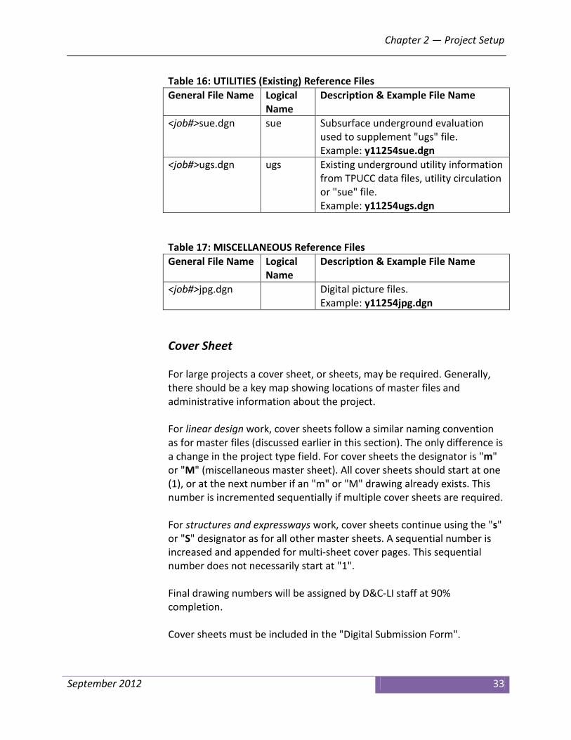
Table 16: UTILITIES (Existing) Reference Files General File Name Logical
Name Description & Example File Name
<job#>sue.dgn sue Subsurface underground evaluation used to supplement "ugs" file. Example: y11254sue.dgn
<job#>ugs.dgn ugs Existing underground utility information from TPUCC data files, utility circulation or "sue" file. Example: y11254ugs.dgn
Table 17: MISCELLANEOUS Reference Files General File Name Logical
Name Description & Example File Name
<job#>jpg.dgn Digital picture files. Example: y11254jpg.dgn
Cover Sheet For large projects a cover sheet, or sheets, may be required. Generally, there should be a key map showing locations of master files and administrative information about the project. For linear design work, cover sheets follow a similar naming convention as for master files (discussed earlier in this section). The only difference is a change in the project type field. For cover sheets the designator is "m" or "M" (miscellaneous master sheet). All cover sheets should start at one (1), or at the next number if an "m" or "M" drawing already exists. This number is incremented sequentially if multiple cover sheets are required. For structures and expressways work, cover sheets continue using the "s" or "S" designator as for all other master sheets. A sequential number is increased and appended for multi-sheet cover pages. This sequential number does not necessarily start at "1". Final drawing numbers will be assigned by D&C-LI staff at 90% completion. Cover sheets must be included in the "Digital Submission Form".

D&C-LI CADD Specification Manual (Version 1.3)
34 September 2012
Base Plan Data Base plan data (ESM, DMOG, CUMAP, etc.) is available for use in linear design work. Designers in D&C-LI can obtain required base mapping through the "CapitalWorks Basemap Template" application developed and maintained by DIS. External consultants will be provided base mapping as part of the deliverables provided in the information package. Information copied from base mapping into design files must be transcribed to the correct D&C-LI level structure.
CADD File Naming Convention
The City file naming convention used must be applied throughout the entire project. File Renaming Renaming previously created digital files must be avoided. The exception to this rule is when the master file(s) will be renamed prior to the tendering stage. This change must be authorized only by the respective district Design CADD Plans Administrative Supervisor or authorized staff in Design & Construction – Linear Infrastructure.
Additional Documentation For more information about obtaining and preparing base plan data, please refer to the Base Plan Preparation reference document. See "Appendix D, Additional Documentation" for document file name.

Chapter 3 — Title Blocks and Revisions
September 2012 35
Chapter 3 Title Blocks and Revisions
Title Block
All master design files must have a title block. A standardized title block is created by placing the appropriate "surround" cell from the v8_surrounds_1.3.dgnlib cell DGN library (dgnlib). The blank fields in the standard surround cell, generally "tagged" text, must be filled in or edited accordingly. A blank title block is shown in Figure 2 below.
Figure 2: Blank Title Block Main Information The "Main Information" area contains the following "tagged" text fields to fill in: • project street name or structure name • limits (from | to) shown on the particular sheet • project work type Figure 3 (next page) shows the "Main Information" area field in the title block.

D&C-LI CADD Specification Manual (Version 1.3)
36 September 2012
Figure 3: Blank Title Block Showing "Main Information" Area Date The "Date" area field has the date of the last change made and is shown using the "month day, year" format (for example — July 11, 2011). All submitted drawings will include the latest up-to-date "Date". The "Date" is a "tagged" text field Figure 4 shows the "Date" area field in the title block.
Figure 4: Blank Title Block Showing "Date" Area
Main Information
Area (tagged text)
Date Area
(tagged text)

Chapter 3 — Title Blocks and Revisions
September 2012 37
Drawing Number The "Drawing Number" area "tagged" text field must be populated with the correct drawing number. The drawing number naming convention for the title block drawing number is described in detail in the previous chapter, "Chapter 2, Drawing Setup" of this manual. Figure 5 shows the "Drawing Number" area field in the title block.
Figure 5: Blank Title Block Showing "Drawing Number" Area Scale – Linear Design Work For linear work the "Scale" area field is shown in horizontal for plan view and vertical for profile view. All Design & Construction – Linear Infrastructure plans will be drawn to the following scales: • Horizontal 1 : 200 • Vertical 1 : 100 If only "horizontal" information is shown on the drawing, then the "vertical" component can be excluded (i.e. deleted). If only "vertical" information is shown on the drawing, then the "horizontal" component can be excluded (i.e. deleted). The "Scale" area field is not a "tagged" text field. Figure 6 (next page) shows the "Scale" area field in the title block of the linear design surround.
Drawing Number
Area (tagged text)

D&C-LI CADD Specification Manual (Version 1.3)
38 September 2012
Figure 6: (LI) Blank Title Block Showing "Scale" Area Scale – Structures and Expressways Design Work For structures and expressways work all "details" should have the scale noted unambiguously. All scaled reference attachments should have the scale noted. Final plot scales are at the discretion of the City's project manager. The "Scale" area field in the surround for Structures and Expressways differs slightly from the one pictured in Figure 6. If only one scale is used throughout the drawing, then this scale can be noted in the area field. If the drawing shows multiple details at different scales, then "as noted" should be placed in the "Scale" area field. See Figure 7.
Figure 7: (S&E) Blank Title Block Showing "Scale" Area
Scale Area
Scale Area

Chapter 3 — Title Blocks and Revisions
September 2012 39
Design, Drawn and Checked The "Design, Drawn and Checked" area fields must include the names of any individuals who performed these tasks. Use the first initial with full last name whenever possible. The "Design, Drawn and Checked" area is a "tagged" text field. Figure 8 shows the "Design, Drawn and Checked" area fields in the title block.
Figure 8: Blank Title Block Showing "Design, Drawn and Checked" Area Contract Number The "Contract Number" area field is only filled in for final tendered contract drawings. There may be more than one contract number for a given project (depending on the type of work). Contract numbers should be obtained from the D&C-LI district supervisor in the project area. The "Contract Number" area is a "tagged" text field. Figure 9 (next page) shows the "Contract Number" area field in the title block.
Designed, Drawn and Checked
Area (tagged text)

D&C-LI CADD Specification Manual (Version 1.3)
40 September 2012
Figure 9: Blank Title Block Showing "Contract Number" Area
Sheet The "Sheet" area field is for tracking multiple sheets for the same project. This is an optional field but should be used for larger projects. The "Sheet" area is a "tagged" text field. For linear design work, something like "1 of xx" should be used to indicate the number of sheets. For structures and expressways work, a discipline identifier and sequential number can be used. For example, if electrical work is featured on the drawings, something like "E1, E2, E3, etc." can be used. Discipline identifier naming is not enforced as long as there is no ambiguity. Figure 10 (next page) shows the "Sheet" area field in the title block.
Contract Number Area
(tagged text)

Chapter 3 — Title Blocks and Revisions
September 2012 41
Figure 10: Blank Title Block Showing "Sheet" Area Professional Seals Drawings that require a professional signature will be sealed, signed and dated by a professional engineer licensed to practice in the province of Ontario. Apply seal, sign and date by hand. Signature and date must be applied by hand. The seal and date must be clearly legible. Figure 11 shows the "Professional Seals" area.
Figure 11: Engineer's Professional Seal Engineering Consultant's Information and Disclaimer The engineering consultant seal area of the title block shall be filled in if the design is produced by the consulting engineer retained by the City.
Sheet Area
(tagged text)

D&C-LI CADD Specification Manual (Version 1.3)
42 September 2012
Revisions
All revisions to any CADD drawing will be made to the respective CADD digital file. Hand drawn modifications are not permitted. Revision Notes The revision notes box must have the fields filled in after the revision to the CADD digital drawing is completed. The following table lists the fields and gives a brief description of the contents.
Table 18: Revision Notes Fields Field Name Description No. Sequential number beginning at the number one (1) DATE Current date in month-day-year format (06-25-2011) REVISIONS Short description of the revision made INITIAL Initials of the individual that completed the revision SIGNED Signature of individual that completed the revision
Figure 12: Revision Notes A revision symbol will be placed in the body of the drawing indicating the location to which the title block revision note applies to. This revision symbol will be shown as a triangle with the corresponding revision number inside the triangle.

Chapter 4 — Drawing and Plotting
September 2012 43
Chapter 4 Drawing and Plotting
Drawing
Task Manager The MicroStation "Task Manager" is a tool to facilitate automatic drawing functions associated with design within D&C-LI. It is part of the available MicroStation tools. All linear features such as multi-lines, cells, models, text settings, dimension settings, etc. have been incorporated into the "Task Manager" to enable design staff to automatically place design features and to manage various CADD settings associated with design. The "Task Manager" has been configured to allow element placement without having to set any graphic attributes (level, line style, colour, weight, etc.). The designer need only to select the required task and "Task Manager" will automatically place elements with the correct settings and attributes. It is recommended that the MicroStation "Task Manager" be used for all design work. Comprehensive on-line help is available through the "Task Manager" detailing all tasks and showing some sample drawings.
Additional Documentation For more information about the "Task Manager" and its use for D&C-LI design, please refer to the following reference documents:
• City of Toronto Task Manager • City of Toronto Design & Construction – Linear
Infrastructure MicroStation Linear Tasks (Tree Structure) – v1.3
See "Appendix D, Additional Documentation" for document file names.

D&C-LI CADD Specification Manual (Version 1.3)
44 September 2012
Cells and Cell Libraries Standard cells are grouped in various DGN libraries (cell libraries). Cell libraries have a "dgnlib" extension and can be used as libraries or models. The consulting engineer will attach the appropriate cell library, choose an active cell, and place it with in the design drawing. Only cells contained in the approved DGN libraries should be used. Shared cells are not to be used. Cells should not be dropped (broken into individual graphic components). The exception to dropping cells is for "surround" cells which require the title block information to be modified for each project. The following table lists the available cell DGN libraries delivered in the information package. Table 19: Cell DGN Libraries DGN Library Contains v8_cells_master_1.3.dgnlib cell models ; patterning models ;
terminators v8_cells200_1.3.dgnlib miscellaneous models v8_flags_1.3.dgnlib models for InRoads resources v8_surrounds_1.3.dgnlib surrounds ; cover pages ; surround
features v8_utilities_1.3.dgnlib utility models ; existing & proposed in
plan & profile v8_wfittings_1.3.dgnlib watermain fittings in plan & profile
Additional Documentation For more information about the D&C-LI cells, please refer to the Design & Construction Linear Infrastructure – Version 1.3 MicroStation Cells reference document. All cells from the cell DGN libraries are shown in the document. See "Appendix D, Additional Documentation" for document file name.

Chapter 4 — Drawing and Plotting
September 2012 45
Orientation Some notes on orientation follow. • Orient plans so that stationing progresses from right to left. This is
south to north.
Figure 13: Orientation from South to North • Orient plans so that stationing progresses from left to right. This is
west to east.
Figure 14: Orientation from West to East • Orient plans so that north points up the sheet, wherever possible. • Insert a standard north arrow in the top right corner, unless included
in the key plan.
• If true geographic north cannot be used, establish and insert a project north arrow.

D&C-LI CADD Specification Manual (Version 1.3)
46 September 2012
• Orient views in the same direction.
• Orient drawings, notes, and dimensions so that they can be read from the bottom right hand side of the sheet.
• Rotate MicroStation views so as to orient drawings horizontally or
vertically.
• Do not move, rotate or scale plan view CADD data for "linear" work.
• Move, scale, and rotate referenced border file as required.
Scale Elements placed within a MicroStation design file should be drawn at a scale of 1:1 (no scaling). This is the case for all linear design work. For structures and expressways design work, "detail" information should be drawn at 1:1 and then reference scaled accordingly. The scale of the "detail" must be noted unambiguously.

Chapter 4 — Drawing and Plotting
September 2012 47
Line Weight Line weight differences must be clearly visible on both full and half size plots. The following table is to be used as a guide. Table 20: MicroStation Line Weight to Metric Width Chart MicroStation Line Weight (wt=) Metric Width (mm) 0 0.13 1 0.18 2 0.20 3 0.25 4 0.30 5 0.35 6 0.40 7 0.45 8 0.50 9 0.60 10 0.70 11 0.80 12 1.00 13 1.20 14 1.40 15 1.50 16 1.60 17 1.80 18 2.00 19 2.25 20 3.00 For information about the recommended line weights and corresponding metric width when plotted in full size, please see the "Plotting" section in this chapter.

D&C-LI CADD Specification Manual (Version 1.3)
48 September 2012
Line Styles Line styles are stored in resource (rsc) files and should be loaded through a MicroStation "WorkSpace" (as previously discussed). The following table lists the resource line style files delivered in the information package. Table 21: Line Style Resource Files RESOURCE FILE CONTAINS svylstyl_1.3.rsc engineering survey line styles esm_udls_1.3.rsc topographic mapping line styles englstyl_1.3.rsc engineering line styles (compatibility) acadlstyl_1.3.rsc AutoCAD line styles v8_custom_linestyles_1.3.rsc D&C-LI line styles Most custom line styles developed by the City for design work will be located in the v8_custom_linestyles_1.3.rsc file. The creation of new line styles is not permitted. Patterns and Hatching Apply any necessary patterns to detail on small scale drawings. Use the standard patterns as delivered with MicroStation or as provided in the v8_levels_1.3.dgnlib DGN library. Using MicroStation "Task Manager" will simplify drafting operations by setting the correct pattern or hatching based on the selected task. It is up to the designer to select the correct tool for patterns and hatching, depending on the type of element(s) that is to be patterned or hatched.
Additional Documentation For more information about the D&C-LI line styles, please refer to the Design & Construction Linear Infrastructure – Version 1.3 MicroStation Line Styles reference document. All line styles from the resource files are shown in the document. See "Appendix D, Additional Documentation" for document file name.

Chapter 4 — Drawing and Plotting
September 2012 49
Text Style and Size Fill text nodes, data fields and tags with text using uppercase letters only. Use standard fonts as delivered with MicroStation or as provided in the v8_levels_1.3.dgnlib DGN library. All text attributes are pre-set in the MicroStation "Task Manager". Drafting Abbreviations Use abbreviations only when space restricts the spelling of the full word. Match Lines Where partial working areas are shown, display sheet limits by including match lines. Coordinate match lines with adjacent sheets by including the drawing name along the match line and outside of the working area. Key Plan The key plan will be used to show the extent of the working area and spatially relate the project to the surrounding area. Some things to note about key plans: • The key plan is to be located in the top right corner of the surround. • The key plan is to include a north arrow.
Additional Documentation For more information about the D&C-LI text styles, please refer to the Design & Construction Linear Infrastructure – Version 1.3 MicroStation Text Styles reference document. Text styles from the DGN library are shown in the document. See "Appendix D, Additional Documentation" for document file name.

D&C-LI CADD Specification Manual (Version 1.3)
50 September 2012
• The key plan is to highlight the project street and have a least two (2) major arterial roads visible.
• Outline the extent of work covered by each sheet and pattern the working area accordingly.
• Show the location of shut-off valves and hydrants (for watermain projects only).
• Key plans must match the D&C-LI level structure.
Leader Lines Leader lines should have a short horizontal bar leading in and leading out from the text. Use filled arrowheads. Leader lines and auto dimensioning is pre-set in the MicroStation "Task Manager". The v8_levels_1.3.dgnlib DGN library contains these settings. Multi-Lines Multi-lines are pre-set in the MicroStation "Task Manager". These settings reside in the v8_levels_1.3.dgnlib DGN library.
Additional Documentation For more information about the D&C-LI multi line styles, please refer to the Design & Construction Linear Infrastructure – Version 1.3 MicroStation Multi Line Styles reference document. Multi line styles from the DGN library are shown in the document. See "Appendix D, Additional Documentation" for document file name.

Chapter 4 — Drawing and Plotting
September 2012 51
Dimensions All dimensions should be shown in millimetres. Geodetic elevations, chainages, alignments and site drawings should be shown in metres. Dimensions settings are contained in the v8_levels_1.3.dgnlib DGN library. Using MicroStation "Task Manager" will simplify drafting operations by setting the correct dimension style based on the selected task. It is up to the designer to select the correct tool for the dimensioning, depending on where or type of dimension to be placed (eg. linear, angular, etc.). Some things to note about dimensioning: • Use automatic dimensioning — real size length. • Use filled arrowheads for dimension terminators. • Stagger and offset dimension lines from each other starting with
minor dimensions placed close to the working area, then major dimensions and then overall dimension lines.
• Use three (3) decimal places for proposed features (182.137) and two (2) decimal places for existing features (182.14).
Additional Documentation For more information about the D&C-LI dimension styles, please refer to the Design & Construction Linear Infrastructure – Version 1.3 MicroStation Dimension Styles reference document. Dimension styles from the DGN library are shown in the document. See "Appendix D, Additional Documentation" for document file name.

D&C-LI CADD Specification Manual (Version 1.3)
52 September 2012
InRoads "InRoads" is a vertical application for road design from Bentley Systems Incorporated that is used in conjunction with MicroStation. Features in InRoads will be generated using the level names and symbology provided. The following table shows files that must be delivered by the consulting engineer on completion of the project. Table 22: Required InRoads Files File Type Extension Description Required Geometry Projects alg All related alignments yes Surfaces dtm All digital terrain models,
existing and proposed yes
Template Libraries itl All template files yes Roadway Design ird All roadway files yes Reports (various) All supporting reports yes InRoads Projects rwk
prj All InRoads projects optional
A copy of the City "XIN file" for InRoads version 08.11.xx is available on request. For more information about using InRoads for design work, please contact the D&C-LI district supervisor in the project area.
Additional Documentation For more information about setting up InRoads, please refer to the Setting up of InRoads Project Defaults Versions XM, 8iSS1 and (8i in V7 Mode) reference document. See "Appendix D, Additional Documentation" for document file name.

Chapter 4 — Drawing and Plotting
September 2012 53
Specification Checker
To ensure that design CADD files adhere to the graphic specification defined by this version, a specification checker is available for this purpose. The specification checker, developed by Data Integration Services, is a VBA macro launched from MicroStation. Single files or multiple files can be checked with a report generated to indicate any discrepancies. The specification checker can be launched from "Task Manager". The following table lists the files required for the specification checker. Table 23: Files Required for Specification Checker File Name Purpose Design_Spec_Checker_v6.mvba MicroStation VBA macro application. spec_checker_file_v1.3_local.txt Settings file stipulating DGNLIBs to be
scanned. All generated CADD files should be scanned by the specification checker before submission.
Additional Documentation For more information about the D&C-LI specification checker, please refer to the Technical Services CADD Graphic Specification Checker for Bentley MicroStation Design Files user guide. All aspects of the specification checker are covered in this document. See "Appendix D, Additional Documentation" for document file name.
D&C-LI CADD Specification Manual (Version 1.3)
54 September 2012
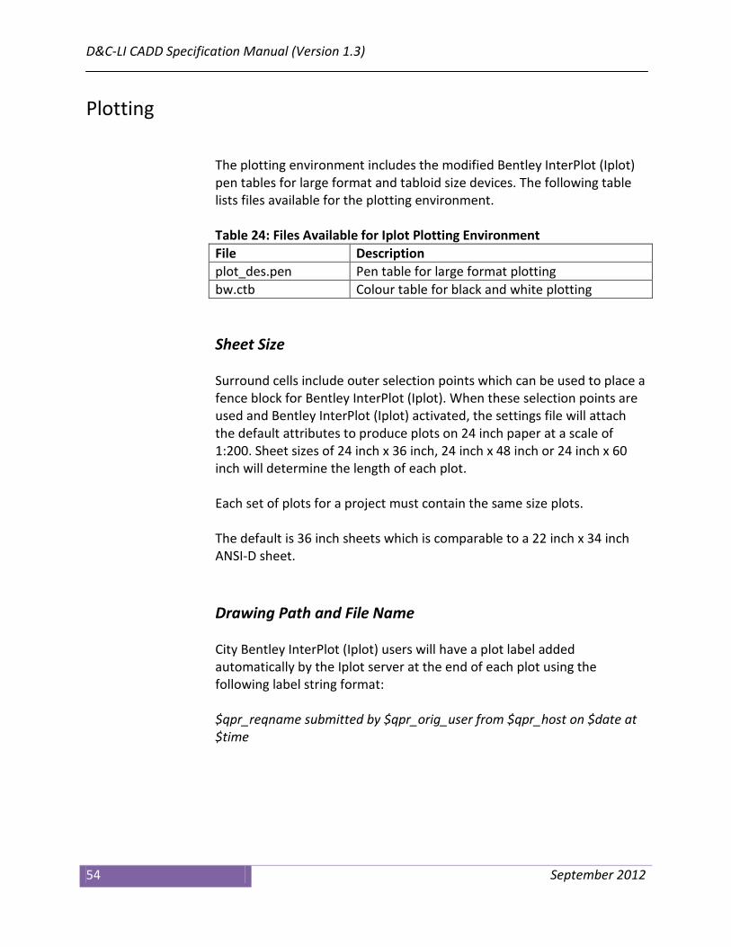
Plotting
The plotting environment includes the modified Bentley InterPlot (Iplot) pen tables for large format and tabloid size devices. The following table lists files available for the plotting environment. Table 24: Files Available for Iplot Plotting Environment File Description plot_des.pen Pen table for large format plotting bw.ctb Colour table for black and white plotting Sheet Size Surround cells include outer selection points which can be used to place a fence block for Bentley InterPlot (Iplot). When these selection points are used and Bentley InterPlot (Iplot) activated, the settings file will attach the default attributes to produce plots on 24 inch paper at a scale of 1:200. Sheet sizes of 24 inch x 36 inch, 24 inch x 48 inch or 24 inch x 60 inch will determine the length of each plot. Each set of plots for a project must contain the same size plots. The default is 36 inch sheets which is comparable to a 22 inch x 34 inch ANSI-D sheet.
Drawing Path and File Name City Bentley InterPlot (Iplot) users will have a plot label added automatically by the Iplot server at the end of each plot using the following label string format: $qpr_reqname submitted by $qpr_orig_user from $qpr_host on $date at $time
Chapter 4 — Drawing and Plotting
September 2012 55
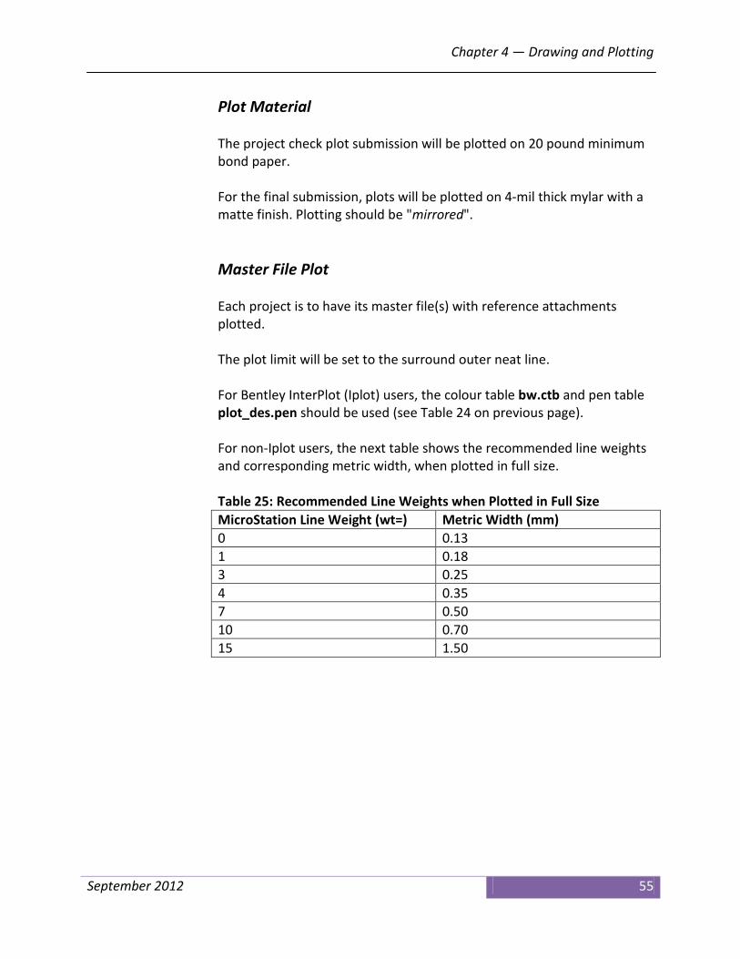
Plot Material The project check plot submission will be plotted on 20 pound minimum bond paper. For the final submission, plots will be plotted on 4-mil thick mylar with a matte finish. Plotting should be "mirrored". Master File Plot Each project is to have its master file(s) with reference attachments plotted. The plot limit will be set to the surround outer neat line. For Bentley InterPlot (Iplot) users, the colour table bw.ctb and pen table plot_des.pen should be used (see Table 24 on previous page). For non-Iplot users, the next table shows the recommended line weights and corresponding metric width, when plotted in full size. Table 25: Recommended Line Weights when Plotted in Full Size MicroStation Line Weight (wt=) Metric Width (mm) 0 0.13 1 0.18 3 0.25 4 0.35 7 0.50 10 0.70 15 1.50

D&C-LI CADD Specification Manual (Version 1.3)
56 September 2012

Chapter 5 — Procedures for Consultants
September 2012 57
Chapter 5 Procedures for Consultants
At the project start-up meeting, the consulting engineer will receive all files required to complete the assignment on CD-ROM. The CD will contain the following: • D&C-LI CADD Specification Manual prepared by the Technical Services
division for use on D&C-LI sewer, watermain and road construction projects.
• Supporting documents referred to in the D&C-LI CADD Specification
Manual.
• City MicroStation files required for the project.
Data Format and Conversion All computer aided design and drafting (CADD) data is provided in Bentley MicroStation version 8 (V8) design file (dgn) format. Any conversion of digital data is not allowed, and may be rejected by the City. The City is not responsible for any inaccuracies, discrepancies or missing information derived from data that is converted outside of the Bentley MicroStation format.
Data Transfer — Data Outgoing from the City
All CADD data transfers outgoing from the City will be completed by staff in the Data Integration Services (DIS) unit.

D&C-LI CADD Specification Manual (Version 1.3)
58 September 2012
Data will be transferred and delivered on CD-ROM or DVD-ROM.
Design & Construction – Linear Infrastructure Disclaimer All data file transfers come with a City CADD disclaimer. The full text of the disclaimer is shown in "Appendix A, Digital CADD Data Disclaimer" of this manual.
Digital Data Submitted to the City
The consulting engineer is required to submit a CADD digital file at each contract milestone as specified in the project documentation. This includes a full submission at the time when the project reaches any of the following milestones, if any such milestones are identified in the contract specification: • 100% design review • Issue for tender • Issue for construction • As-built Additional milestones may be applicable. All file submissions will be delivered to the project engineer, who in turn forwards the digital file to the district CADD administrator. All CADD data submitted must be delivered in Bentley MicroStation version 8 (V8) design file (dgn) format. CADD data in formats other than MicroStation will not be accepted. Data shall be submitted on CD-ROM or DVD-ROM. Any milestone submission will include a complete set of all digital files prepared by the consulting engineer, including any files that have not been modified since any previous submissions, as long as such files are still significant to the project as a whole.

Chapter 5 — Procedures for Consultants
September 2012 59
A "Digital Submission Form" must be completed by the consultant for each submission made. A sample of a completed form may be found in "Appendix B, Digital File Submission Form" of this manual. Submission Review The submission of all digital files will be reviewed by City staff to ensure compliance with the standards and specifications identified in this manual. Files submitted will be checked with a MicroStation specification checker macro developed for Design & Construction – Linear Infrastructure. Submissions failing to meet any of the standards and specifications will be returned to the Design & Construction – Linear Infrastructure unit project engineer along with a listing of all the non-compliant items which will need to be resolved by the consulting engineer. Plotting of Drawings The City utilizes Bentley InterPlot (Iplot) to produce all hard copy plots of CADD data. For more information about plotting, please refer to "Chapter 4, Drawing and Plotting" of this manual. For details regarding submission of drawings in hard copy format, such as frequency and quantities, refer to the specific requirements for your project, or contact the D&C-LI district supervisor in the project area.

D&C-LI CADD Specification Manual (Version 1.3)
60 September 2012

Appendix A – Digital CADD Data Disclaimer
September 2011 61
Appendix A Digital CADD Data Disclaimer
Digital Data Disclaimer:
Information supplied by the City of Toronto, on portable media or transmitted by electronic means, is provided for convenience only. While efforts are made to see that the information contained hereon is accurate and up-to-date; • neither the City of Toronto nor any of its employees, officers or
servants shall be liable for damages arising from any errors or inaccuracies therein, nor from any misuse, misinterpretation or misapplication thereof; and
• the consultant accepts full responsibility for verifying the accuracy
and completeness of the data supplied hereon and assumes full responsibility for any risk associated with the use, misuse, misinterpretation or misapplication thereof; and
• the said information is not included under the seals or certificates, if
any, on any accompanying plans or printed material; and
• in the event of inconsistencies between said information and hard copy data, the hard copy data shall govern.
All data provided remains the property of the City of Toronto. All rights reserved. No portion of this document may be copied or distributed without prior written consent. The City of Toronto considers any information that is not part of the public domain, such as parts of drawings that identify non-public areas to be confidential. Any confidential information is transmitted subject to the terms of your contract with the City, or subject to the non-disclosure agreement executed with the City for this purpose.

D&C-LI CADD Specification Manual (Version 1.3)
62 September 2012

Appendix B — Digital File Submission Form
September 2012 63
Appendix B Digital File Submission Form
Digital File Submission Form
Contract: SAMPLE Disks (#) or
Other: DISK 1 of 3
Project Description:
DONINO COURT FROM DONINO AVENUE TO 60M E OF DONINO AVENUE – LOCAL ROAD RECONSTRUCTION /WATERMAIN
SAMPLE
Submitted By: CONSULTANT
File Particulars Hard Copy
Plan Number Digital File
Name Type
of File Description
P-5408-001 P-5408-001 MASTER PLAN SURROUND Y07273PD REFERENCE PAVEMENT DESIGN Y07273SD REFERENCE SEWER DESIGN
PLEASE COMPLETE THE ABOVE TABLE. List all hard copy plan numbers for this project and the corresponding digital files
which comprise each individual drawing.
(Also include all reference files, if applicable)

D&C-LI CADD Specification Manual (Version 1.3)
64 September 2012

Appendix C — Settings for MicroStation V8
September 2012 65
Appendix C Bentley MicroStation Resources
File Locations For the table below in the "Folder Location" column:
• Folder A refers to c:\f\projects\microstation\v8_resources_version_1_3\ • Folder B refers to c:\f\projects\microstation\v8_resources_version_1_3\models • Folder C refers to c:\f\projects\microstation\v8_resources_version_1_3\help
Table 26: MicroStation File Locations File Name Folder
Location Description
v8_seed_2d_1.3.dgn A Main 2D seed file. v8_seed_3d_1.3.dgn A Main 3D seed file. v8_dcli_1.3.ucf A MicroStation user configuration file. acadlstyl_1.3.rsc A AutoCAD line styles. englstyl_1.3.rsc A Engineering line styles. esm_udls_1.3.rsc A Topographic mapping line styles. svylstyl_1.3.rsc A Engineering survey line styles. v8_custom_linestyles_1.3.rsc A D&C-LI custom line styles. xfont_1.3.rsc A Text fonts. engcolor_1.3.ctb A Engineering colour table. v8_levels_1.3.dgnlib A Levels ; multi-line settings ; dimension
settings ; text settings ; tasks plot_des.pen A Iplot pen table for large format plotting bw.ctb A Colour table for black and white plotting v8_cells_master_1.3.dgnlib B Cell models ; patterning models ; terminators. v8_cells200_1.3.dgnlib B Miscellaneous models. v8_flags_1.3.dgnlib B Models for InRoads resources. v8_surrounds_1.3.dgnlib B Surrounds ; cover pages ; surround features. v8_utilities_1.3.dgnlib B Utility models ; existing &proposed in plan &
profile. v8_wfittings_1.3.dgnlib B Watermain fitting in plan & profile. Design_Spec_Checker_v6.mvba A Specification checker VBA macro. spec_checker_file_v1.3_local.txt A Settings file for specification checker macro.

D&C-LI CADD Specification Manual (Version 1.3)
66 September 2011
Table 26: MicroStation File Locations (continued) File Name Folder
Location Description
help.pdf C On-line help file for "Task Manager". Tasks_1.3.html C On-line help file for "Task Manager".

Appendix D — Additional Documentation
September 2012 67
Appendix D Additional Documentation
Additional documentation is available to supplement this manual. This documentation can be found in the following folder location:
• c:\f\projects\microstation\v8_resources_version_1_3\help The following table lists the supplementary documentation. Table 27: Available Additional Documentation for Version 1.2 Document Title Document File Name Document Contents Design & Construction Linear Infrastructure Version 1.3 MicroStation Levels
LI_Level_Names_V103000.pdf List of all D&C-LI level names and associated graphic attributes.
Design & Construction Linear Infrastructure Version 1.3 MicroStation Cells
LI_Cells_V103000.pdf List of all D&C-LI cells and their graphic representation.
Design & Construction Linear Infrastructure Version 1.3 MicroStation Line Styles
LI_LineStyles_V103000.pdf List of all D&C-LI line styles and their graphic representation.
Design & Construction Linear Infrastructure Version 1.3 MicroStation Multi Line Styles
LI_MultiLineStyles_V103000.pdf List of all D&C-LI multi line styles and their graphic representation.
Design & Construction Linear Infrastructure Version 1.3 MicroStation Text Styles
LI_TextStyles_V103000.pdf List of all D&C-LI text styles and their graphic representation.
Design & Construction Linear Infrastructure Version 1.3 MicroStation Dimension Styles
LI_DimensionStyles_V103000.pdf List of all D&C-LI dimension styles and their graphic representation.
City of Toronto Task Manager
City_of_Toronto_Task_Manager.pdf User guide for the MicroStation Task Manager

D&C-LI CADD Specification Manual (Version 1.3)
68 September 2011
Table 27: Available Additional Documentation for Version 1.2 (continued) Document Title Document File Name Document Contents City of Toronto Design & Construction – Linear Infrastructure MicroStation Linear Tasks (Tree Structure) – v1.3
Tasks_1.3.html List of all tasks associated with "Task Manager" and their hierarchy. This is also an on-line help file.
Technical Services CADD Graphic Specification Checker for Bentley MicroStation Design Files
TS_Specification_Checker_User_Guide.pdf
User guide for the specification checker.
TIMS Overview – City Data Manager
TIMS_File_Extractions.pdf Brief overview of the TIMS file structure and consultant "Pack and Go" package.
TIMS Structure and Attribution
TIMS_Attribution_Structure.pdf Brief overview of the TIMS attribution structure.
TIMS Indexing Protocols TIMS_Indexing_Protocols.pdf Comprehensive overview of many aspects of TIMS.
TIMS Attributing for As-Builts
TIMS_AsBuilt.pdf Brief overview of attributing "as-built" files in TIMS.
Base Plan Preparation Base_Plan_Prepration.pdf Brief overview for D&C-LI staff of base plan preparation.
Setting up of InRoads Project Defaults Versions XM, 8iSS1 and (8i in V7 Mode)
Setting_Up_InRoads_DCLI.pdf Brief overview of InRoads setup and configuration for D&C-LI design work.
<no title> Miscellaneous_Help_DCLI.pdf Various examples of labels, lines styles, design notes and other information. This is also an on-line help file.
<no title> Cover_Sheet_Example.pdf Example cover sheet. <no title> Detail_Sheet_Example.pdf Example detail sheet. <no title> Watermain_Design_Example.pdf Example watermain design
drawing. <no title> TTC_Road_Resurfacing_Example.pdf Example TTC road
resurfacing drawing.

Appendix E — Digital CADD Contacts
September 2012 69
Appendix E City CADD Contacts
CADD Digital File and Specification Manual Contacts
Design & Construction – Linear Infrastructure CADD Administrators For district specific digital data, contact the respective supervisor in the Design & Construction – Linear Infrastructure office your project is located in. The following table lists the district Design/CADD/Plans Administration Supervisors.
Table 28: District Design/CADD/Plans Administration Supervisors Name District Phone Number E-mail Address Tasha Cheng Etobicoke/York 416-338-1185 [email protected] Carmine Scopelliti North York 416-395-1113 [email protected] Tony Rodrigues Scarborough 416-396-7140 [email protected] Fausto Robalino Toronto/East York 416-392-8855 [email protected] Bill Tsomokos TTC/Special
Projects 416-338-5535 [email protected]
CADD Specification Manual and Related Documentation For errors and omissions or other questions relating to CADD documentation and/or general information about the CADD graphic specification, the following table lists the contact in Data Integration Services.
Table 29: Contact for CADD Documentation Name Title Phone Number E-mail Address Ryk Karczuga Supervisor,
Graphic Data 416-392-9067 [email protected]

D&C-LI CADD Specification Manual (Version 1.3)
70 September 2011
TIMS and Consultant Information Package For information about TIMS or the consultant information package, the following table lists the contact in Data Integration Services.
Table 30: Contact for TIMS Administration Name Title Phone
Number E-mail Address
Phil Fishenden Supervisor, Design/CADD/Plans Administration
416-392-9313 [email protected]
Survey and Utility Mapping Services The following tables list miscellaneous contacts in Survey and Utility Mapping Services.
Table 31: Contact for Utility Mapping (DMOG and CUMAP) Name Title Phone Number E-mail Address Mike Kolominsky Supervisor,
Utility Mapping 416-338-5023 [email protected]
Table 32: Contact for Parcel Mapping Name Title Phone Number E-mail Address John House Supervisor,
Property Records 416-392-8338 [email protected]
Table 33: Contact for Engineering Survey Operations Name Title Phone Number E-mail Address Craig Morris Supervisor,
Engineering Survey
416-392-0355 [email protected]
Table 34: Contact for Engineering Survey Graphic Specification Name Title Phone Number E-mail Address Ryk Karczuga Supervisor,
Graphic Data 416-392-9067 [email protected]

Appendix E — Digital CADD Contacts
September 2012 71
Geospatial Competency Centre The following table lists the contact for Enterprise Stereographic Model (ESM) topographic mapping. This mapping product is no longer under the jurisdiction of Technical Services.
Table 35: Contact for Topographic (ESM) Mapping Name Title Phone Number E-mail Address Desmond Christopher
Supervisor, Street & Parcel Mapping
416-392-1831 [email protected]
Design & Construction – Major Works Facilities For information on trunk sewers and/or transmission watermains, contact the Supervisor, CADD Services in the Design & Construction – Major Works Facilities. The following table lists the contact.
Table 36: Contact for Trunk Sewers and Transmission Watermains Name Title Phone Number E-mail Address Chris Zolcinski Supervisor,
CADD Services 416-397-5358 [email protected]
Transportation Services For information on intersection traffic control devices contact the Supervisor, Traffic Drafting in Transportation Services. The following table lists the contact.
Table 37: Contact for Transportation Services Name Title Phone Number E-mail Address Edith Matay-Swan
Supervisor, Traffic Drafting
416-338-5393 [email protected]

D&C-LI CADD Specification Manual (Version 1.3)
72 September 2011

Glossary
September 2012 73
Glossary
American National Standards Institute (ANSI) – A private non-profit organization that oversees the development of voluntary consensus standards for products, services, processes, systems, and personnel in the United States. Bentley Systems Incorporated or Bentley – The developer and vendor of CADD software (MicroStation, InRoads, etc.) used for design by the Technical Services division of the City of Toronto. By-Level – MicroStation methodology where symbology is explicitly defined for each level. Only that symbology can be used for the level. CADD – Computer Aided Design and Drafting. CADD Administrators – These are contact persons in the Technical Services division, Design and Construction – Linear Infrastructure section. CapitalWorks Basemap Template – A Technical Services web application for downloading City base mapping (topo, utilities, legal, etc.). City – The City of Toronto—the corporation—and will be referred to as the City for the purposes of this document. Consultant – Consulting engineering firm retained by, or on behalf of the city. This reference may also include municipal staff depending on the context. Consulting Engineer – A professional engineer, firm of engineers or a developer retained by the City, skilled and experienced in municipal work and land development projects and registered with the Professional Engineers of Ontario. Contract Administrator – The individual or firm responsible for overseeing the construction of the works and representing the city’s interest. CTB or .CTB – Bentley Systems Incorporated MicroStation colour table file used to define a colour palette for design files.

D&C-LI CADD Specification Manual (Version 1.2)
74 September 2011
CUMAP – Combined Utility Map
ping. This mapping product contains water and sewer information (and some miscellaneous features) for areas outside the former City of Toronto.
D&C-LI or DCLI – Design & Construction – Linear Infrastructure section in the Technical Services division of the City of Toronto. This section was previously called District Engineering Services (DES). D&C-MWF – Design & Construction – Major Works Facilities section in the Technical Services division of the City of Toronto. DES – District Engineering Services section in the Technical Services division renamed to Design & Construction – Linear Infrastructure (see D&C-LI). DGN or .DGN – Bentley Systems Incorporated MicroStation design (drawing) file. DGNLIB or .DGNLIB – Bentley Systems Incorporated MicroStation design library file. DIS – Data Integration Services unit in the Survey & Utility Mapping Services section in the Technical Services division of the City of Toronto. DMOG – Digital Map Owners Group. This mapping product contains water, sewer and other utility information (cable, telephone, gas, etc.) for the former City of Toronto. Engineer – The licensed individual or firm responsible for the design of the works or their designate. Also may be referred to as the design engineer. ESM – Enterprise Stereo Model. This is the topographic mapping data set. InRoads – A CADD road design vertical application from Bentley Systems Incorporated. InterPlot or Iplot – Bentley Systems Incorporated printing and plotting application for CADD designs. lfn_id – A unique number assigned to each street in the City of Toronto.

Glossary
September 2012 75
Linear Design Work – CADD design for watermain, sewer and road projects. LI – Linear Infrastructure. MicroStation – A CADD product from Bentley Systems Incorporated. New project – CADD data based upon standards and specifications included in this manual. S&E – Structures and Expressways. Structures and Expressways Design Work – CADD design for bridges and expressways and associated structures. TIMS – Technical Information Management System software from Ingenium Group. TPUCC – Toronto Public Utilities Coordinating Committee. TTC – Toronto Transit Commission. V7 – Version 7 of Bentley MicroStation. This is an obsolete MicroStation CADD engine using integers for calculations and is no longer used by the Technical Services division. V8 – Version 8 of Bentley MicroStation. This is the current MicroStation CADD engine using floating point for calculations and is the format used by the Technical Services division. ZIP – PkZip compressed archive file

D&C-LI CADD Specification Manual (Version 1.2)
76 September 2011


City of Toronto Technical Services
Data Integration Services 18 Dyas Road – 2nd Floor
Toronto, Ontario M3B 1V5