CAD/CAM - DIMACSdimacs.rutgers.edu/Workshops/CompAided/slides/lee2.pdf · NCSU - YSLee Outlines...
53
Computational Geometric Techniques for Sculptured Surface Manufacturing and CAD/CAM Yuan-Shin Lee, Ph.D., P.E. North Carolina State University Raleigh, NC 27695-7906 U. S. A. October 7, 2003 E-mail: [email protected] http://www.ie.ncsu.edu/yslee
-
Upload
hoangthuan -
Category
Documents
-
view
215 -
download
0
Transcript of CAD/CAM - DIMACSdimacs.rutgers.edu/Workshops/CompAided/slides/lee2.pdf · NCSU - YSLee Outlines...

Computational Geometric Techniques for Sculptured Surface Manufacturing and CAD/CAM
Yuan-Shin Lee, Ph.D., P.E.North Carolina State UniversityRaleigh, NC 27695-7906U. S. A.
October 7, 2003
E-mail: [email protected]
http://www.ie.ncsu.edu/yslee
NCSU - YSLee
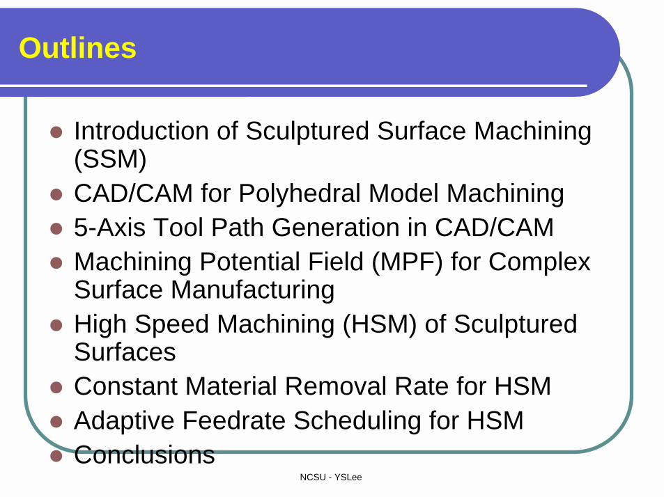
Outlines
� Introduction of Sculptured Surface Machining (SSM)
� CAD/CAM for Polyhedral Model Machining � 5-Axis Tool Path Generation in CAD/CAM� Machining Potential Field (MPF) for Complex
Surface Manufacturing� High Speed Machining (HSM) of Sculptured
Surfaces� Constant Material Removal Rate for HSM� Adaptive Feedrate Scheduling for HSM� Conclusions

NCSU - YSLee
1. Introduction of Sculptured Surface Machining (SSM)

NCSU - YSLee
Product Design with Sculptured Surfaces

NCSU - YSLee
NURBS Surface and Applications
The NURBS surface interpolating four boundary curves.
NURBS surface of the core pattern
NCSU - YSLee
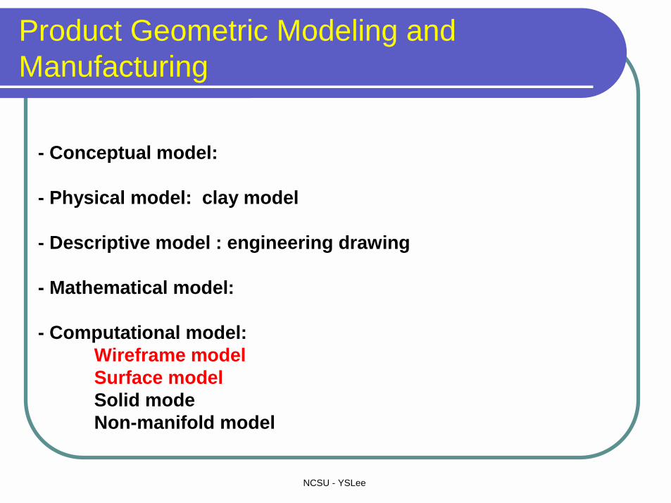
Product Geometric Modeling and Manufacturing
- Conceptual model:
- Physical model: clay model
- Descriptive model : engineering drawing
- Mathematical model:
- Computational model:Wireframe modelSurface model Solid modeNon-manifold model

NCSU - YSLee
Introduction to Sculptured Surface Machining (SMM)
Copy milling NC milling

NCSU - YSLee
2. CAD/CAM for Polyhedral Model Machining
NCSU - YSLee
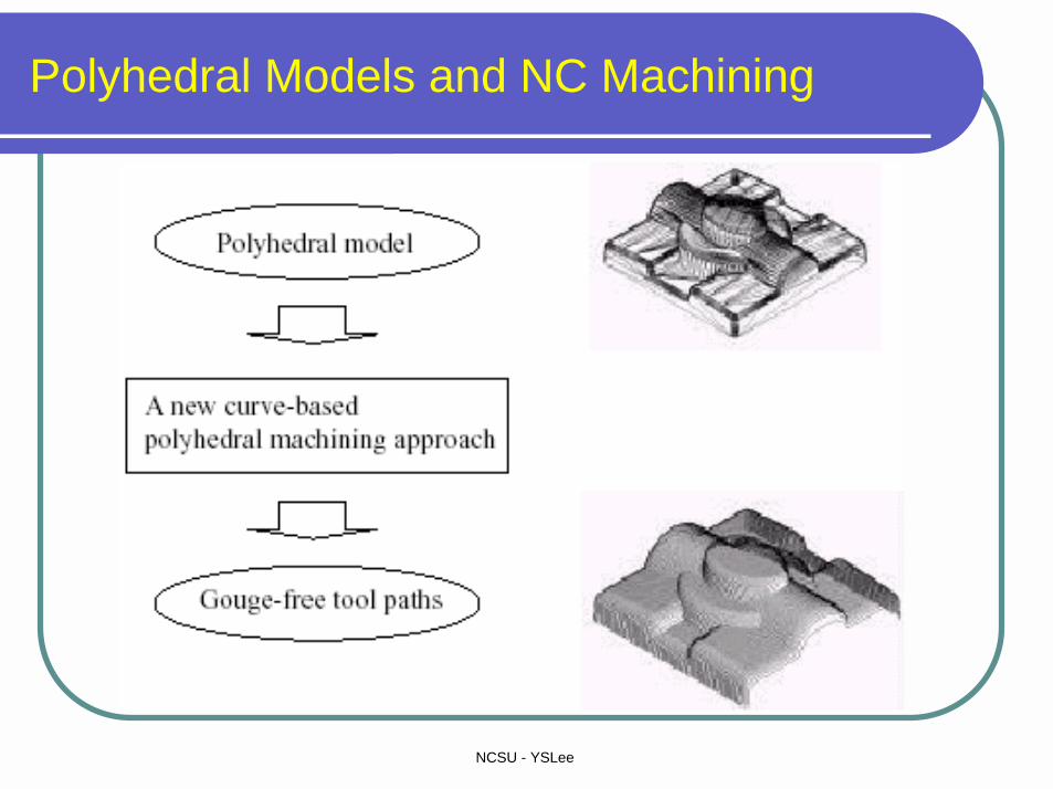
Polyhedral Models and NC Machining

NCSU - YSLee
Cutter Gouging Problems in Sculptured Surface Machining
NCSU - YSLee
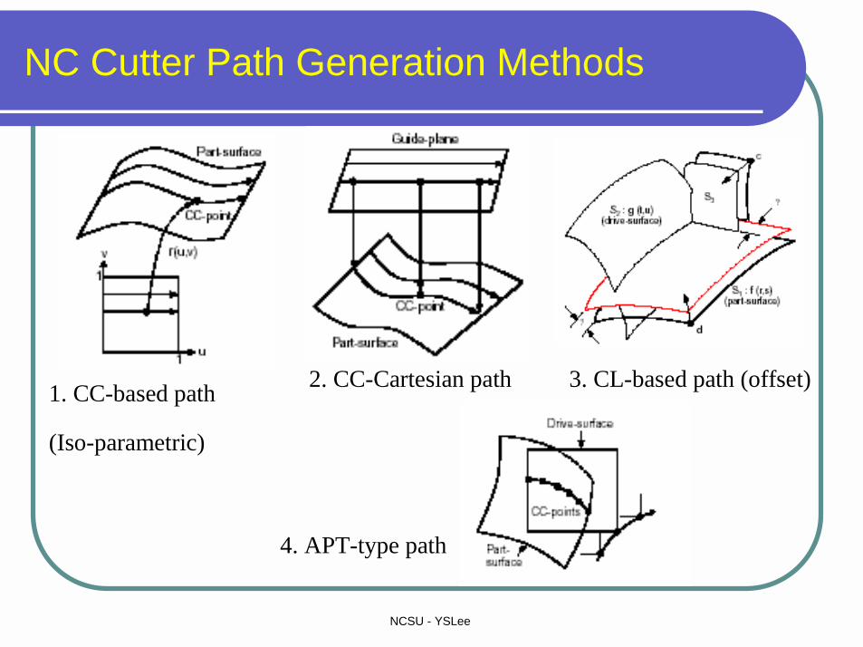
NC Cutter Path Generation Methods
1. CC-based path
(Iso-parametric)
2. CC-Cartesian path 3. CL-based path (offset)
4. APT-type path
NCSU - YSLee
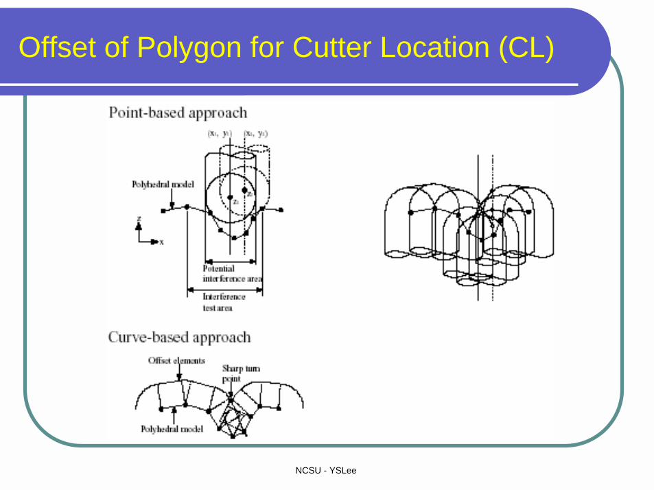
Offset of Polygon for Cutter Location (CL)

NCSU - YSLee
Three Schemes of Polyhedral Offsetting
NCSU - YSLee
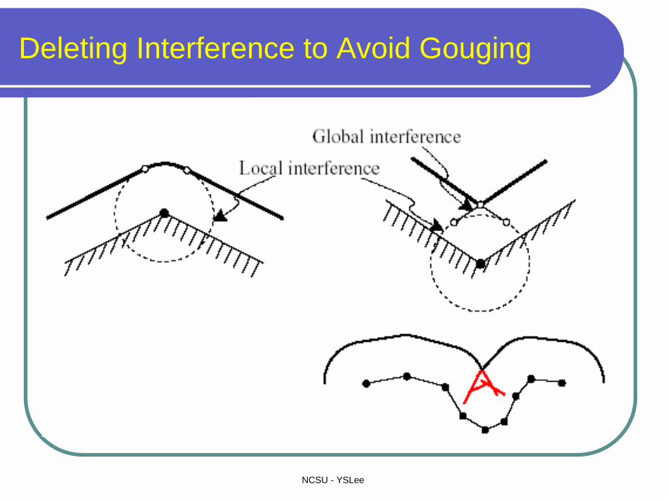
Deleting Interference to Avoid Gouging

NCSU - YSLee
Offset of Triangles and Edges of Polyhedral Models

NCSU - YSLee
Offset of Vertex in Polyhedral Models

NCSU - YSLee
Local Offset Example

NCSU - YSLee
Tool Path Generation for Polyhedral Machining

NCSU - YSLee
Cutter Path Generation for NC Machining
Ball-endmill Filleted-endmill Flat-endmill
CC Point: Cutter contact point
CL Point: Cutter location point
NCSU - YSLee
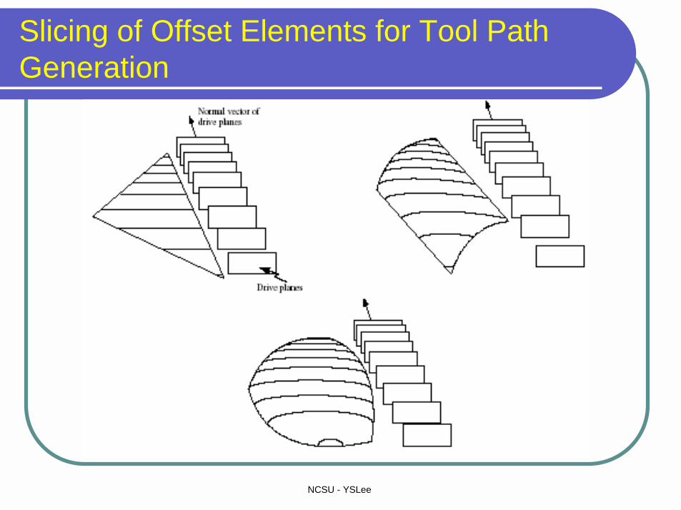
Slicing of Offset Elements for Tool Path Generation
NCSU - YSLee
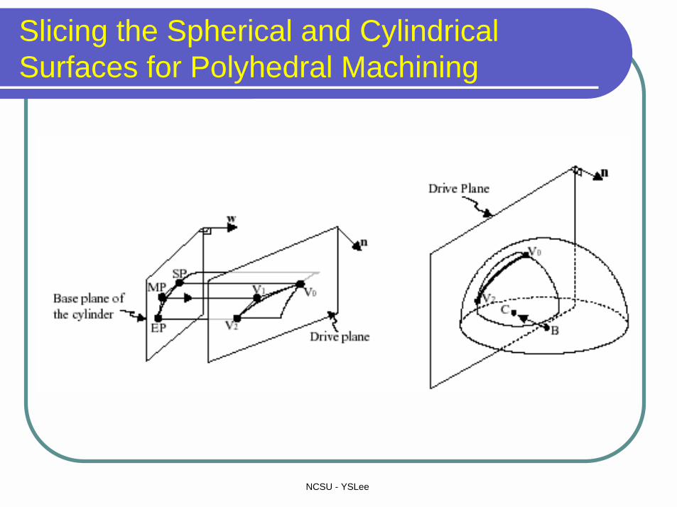
Slicing the Spherical and Cylindrical Surfaces for Polyhedral Machining
NCSU - YSLee
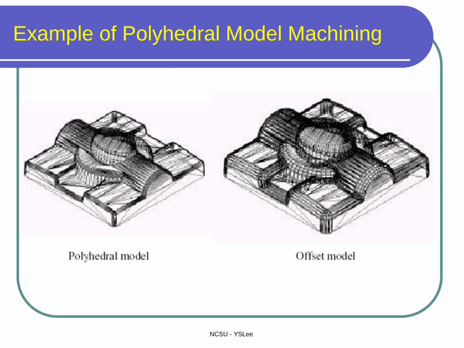
Example of Polyhedral Model Machining
NCSU - YSLee
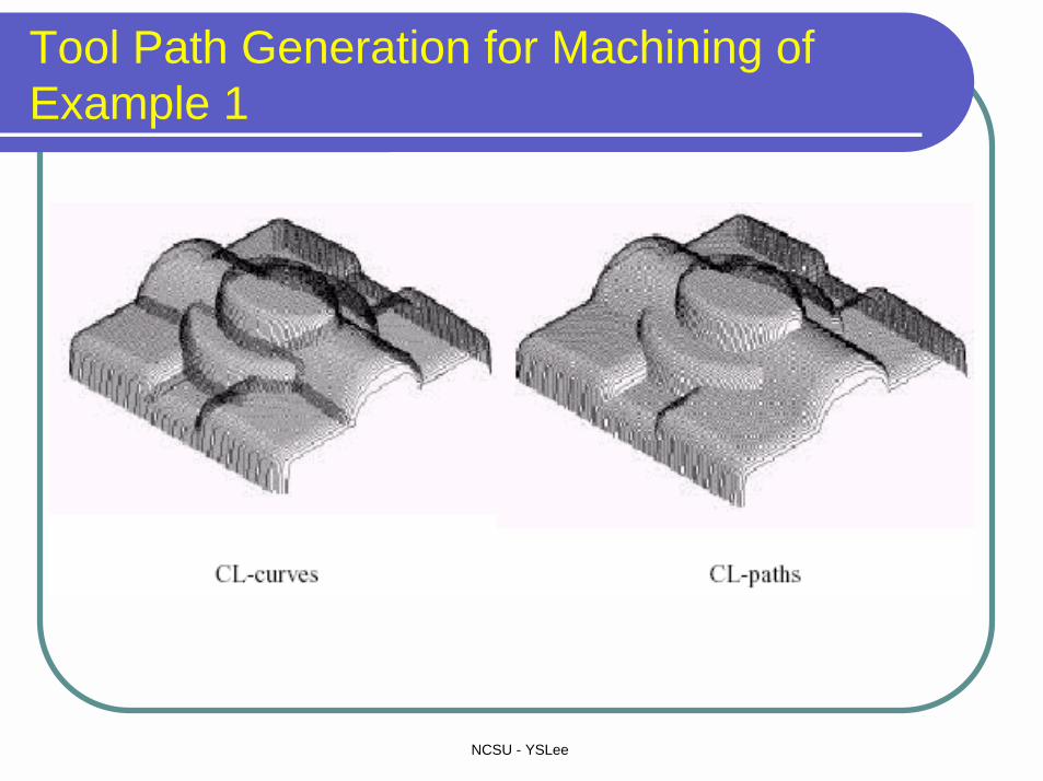
Tool Path Generation for Machining of Example 1

NCSU - YSLee
Polyhedral Machining with Fillet-Endmills
Offset and Slicing of Convex Edges with Fillet Endmills
NCSU - YSLee
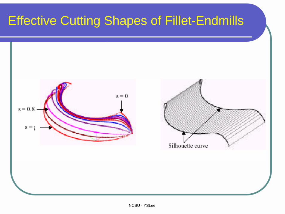
Effective Cutting Shapes of Fillet-Endmills
NCSU - YSLee
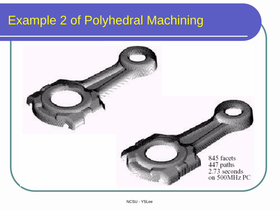
Example 2 of Polyhedral Machining
NCSU - YSLee
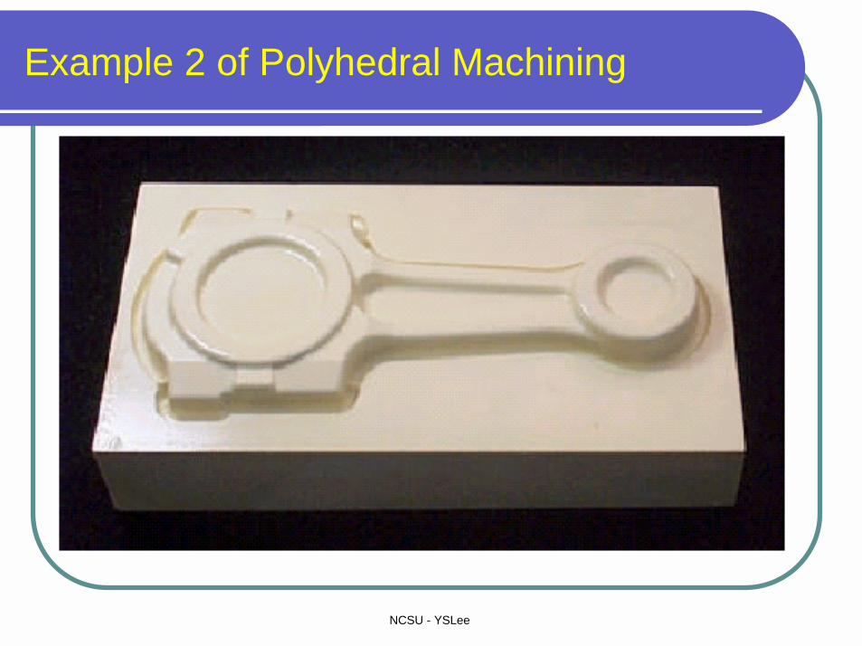
Example 2 of Polyhedral Machining

NCSU - YSLee
Computation Time for Machining Examples
NCSU - YSLee
3. 5-Axis Tool Path Generation for Sculptured Surface Machining (SSM)
NCSU - YSLee
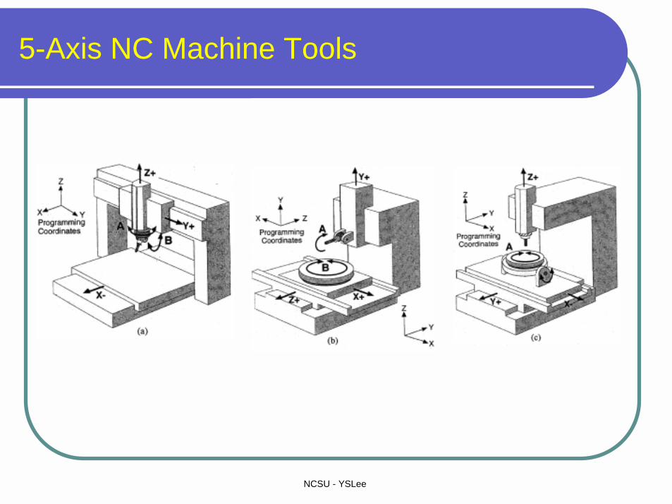
5-Axis NC Machine Tools
NCSU - YSLee
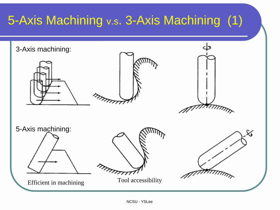
5-Axis Machining v.s. 3-Axis Machining (1)
3-Axis machining:
5-Axis machining:
Efficient in machining Tool accessibility
NCSU - YSLee
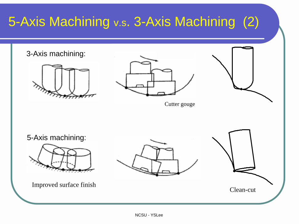
5-Axis Machining v.s. 3-Axis Machining (2)
Cutter gouge
Improved surface finishClean-cut
3-Axis machining:
5-Axis machining:
NCSU - YSLee
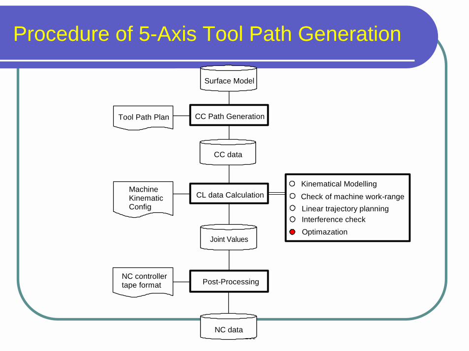
Procedure of 5-Axis Tool Path Generation
Surface Model
CC Path GenerationTool Path Plan
CC data
MachineKinematic Config
CL data Calculation
Joint Values
Post-ProcessingNC controllertape format
NC data
Kinematical ModellingCheck of machine work-rangeLinear trajectory planningInterference checkOptimazation
NCSU - YSLee
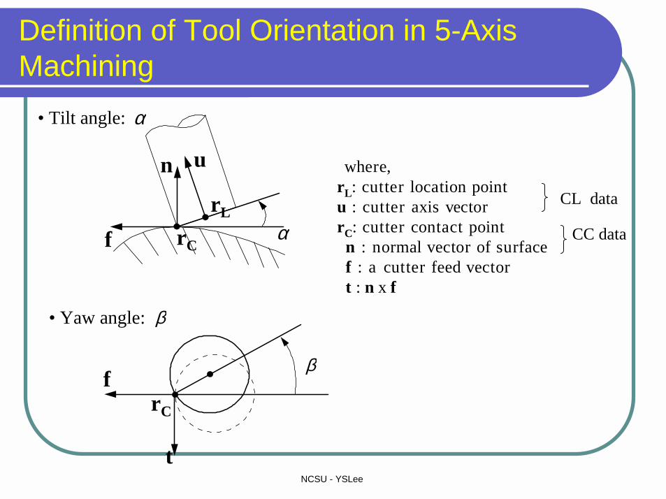
Definition of Tool Orientation in 5-Axis Machining
αrC
n u
rL
f
β
rC
f
t
where,rL: cutter location pointu : cutter axis vector rC: cutter contact point
n : normal vector of surfacef : a cutter feed vectort : n x f
β• Yaw angle:
CL data
CC data
• Tilt angle: α
NCSU - YSLee
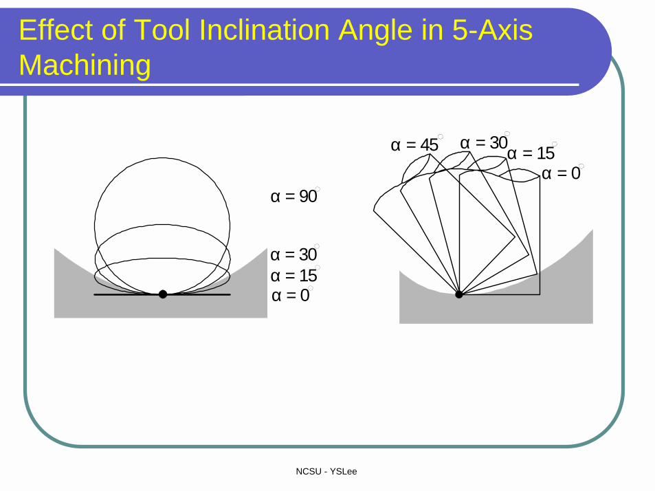
Effect of Tool Inclination Angle in 5-Axis Machining
α = 0
α = 90
α = 30α = 15
α = 45 α = 30α = 15α = 0
NCSU - YSLee
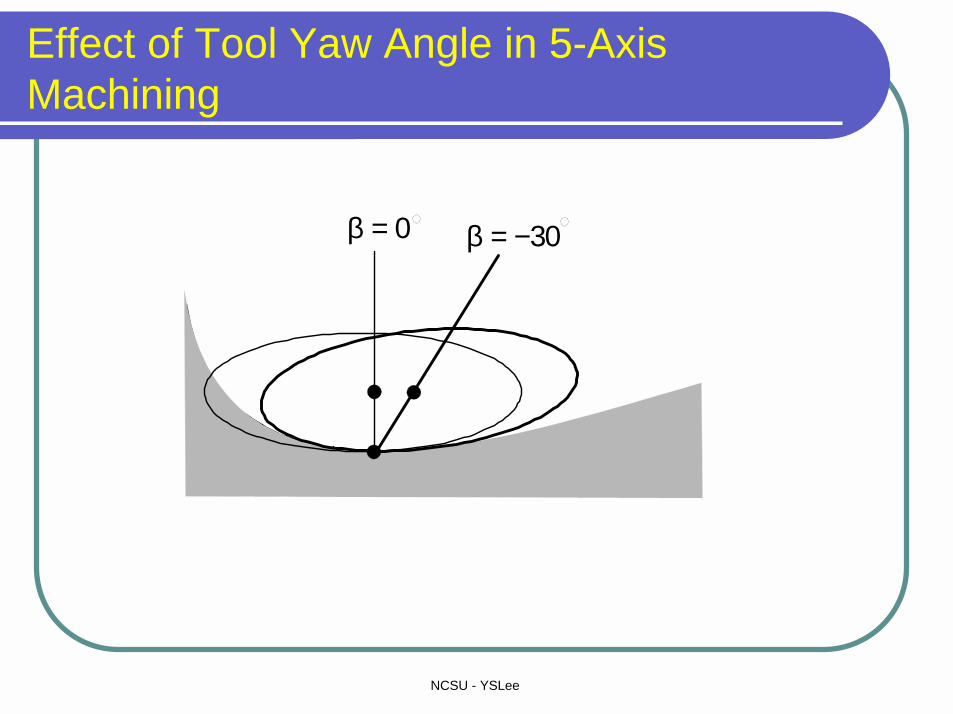
Effect of Tool Yaw Angle in 5-Axis Machining
β = 0 β = −30

NCSU - YSLee
Cusp Height Errors in Sculptured Surface Machining
hle ft h r ight
η
ω
ρ
ω/2
ρ−η3-axis machining:
p1
ω
θ
a
ω
(a) (b)
p2 p1 p2
η η
5-axis machining:
NCSU - YSLee
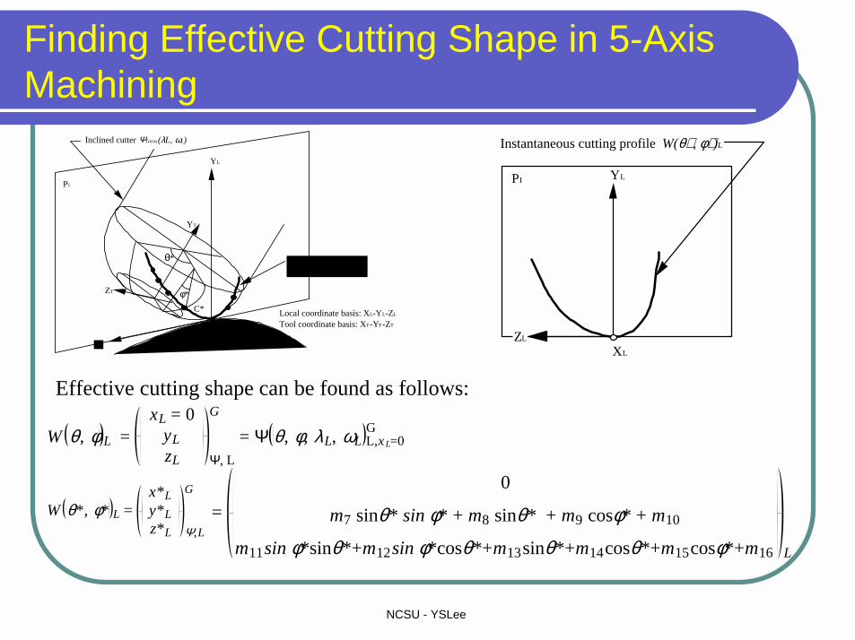
Finding Effective Cutting Shape in 5-Axis Machining
W θ, φL = xL = 0
yLzL Ψ, L
G
= Ψ θ, φ, λL, ωL L,x L=0G
Effective cutting shape can be found as follows:
W θ*, φ* L = x*Ly*Lz*L Ψ,L
G
= 0
m7 sinθ* sin φ* + m8 sinθ* + m9 cosφ* + m10
m11sin φ*sinθ*+m12sin φ*cosθ*+m13sinθ*+m14cosθ*+m15cosφ*+m16 L
Local coordinate basis: XL-YL-ZL
Tool coordinate basis: XT-YT-ZT
PI
CC
θ*
φ*
C*
XLZL
YL
YT
ZT
Instantaneous cutting profile W(θ,φ)L
Inclined cutter ΨTorus(λL, ωL)
YL
ZL
XL
Instantaneous cutting profile W(θ∗ , φ∗)L
PI
NCSU - YSLee
3. Optimizing Tool Path Generation for CAD/CAM Systems

NCSU - YSLee
Machining of Sculptured Surfaces
Traditional machining planning 3D path planning

NCSU - YSLee
Rolling-Ball Method for Extracting Clear-Cut Regions
Xy
z
Gouging free region
Clean-up region
Clean-up boundary
partially-gouging facets
Totally-gouging facets
gouging-free facets
A ball-end cutter
NCSU - YSLee
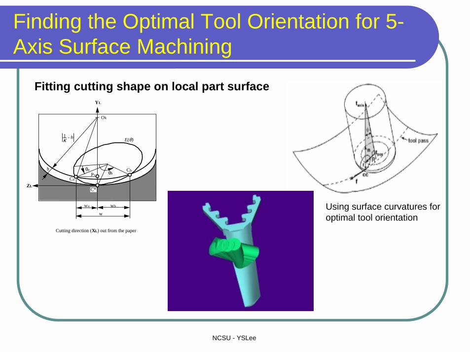
Finding the Optimal Tool Orientation for 5-Axis Surface Machining
Fitting cutting shape on local part surface
ZL
YL
θaθb
h
C*
wa wb
Ca
Cb
Ok
Pv
1κ - h E(θ)
w
Cutting direction (XL) out from the paper
Using surface curvatures for optimal tool orientation
NCSU - YSLee
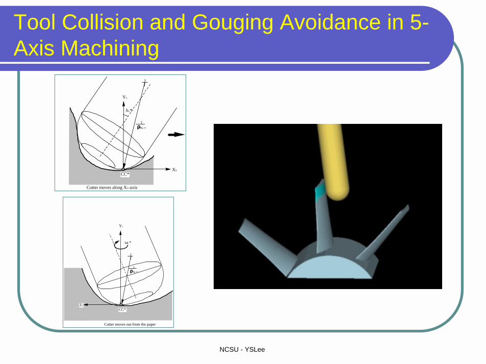
Tool Collision and Gouging Avoidance in 5-Axis Machining
CC*ZL
Cutter moves out from the paper
YL
1ρρρρXL=0
ωL*
CC*XL
Cutter moves along XL-axis
YL
λL*
1ρρρρZL=0
NCSU - YSLee
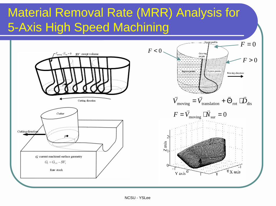
Material Removal Rate (MRR) Analysis for 5-Axis High Speed Machining
0<F0>F
0=F
disrotntranslatiomoving DVV����
⋅Θ+=
0surmoving =⋅= NVF��

NCSU - YSLee
Optimizing 5-Axis Tool Path Generation in CAD/CAM
(Total tool path length = 425.02 units, tool path number = 41, given tolerance = 0.005 units)
Q: Is it possible to find the best path distribution for SSM?
Sculptured surface design Traditional tool path planning

NCSU - YSLee
Optimizing 5-Axis Tool Path Generation
ZL
YL
θaθb
h
C*
wa wb
Ca
Cb
Ok
Pv
1κ - h E(θ)
w
Cutting direction (XL) out from the paper
Machining strip width(dependent of λ, ω)
Optimal cutting direction
- What is the best cutting direction?

NCSU - YSLee
Machining Potential Field (MPF) for Sculptured Surface Machining
Sculptured surface design Machining potential patches
Q: Is it possible to find the best path distribution for SSM?
NCSU - YSLee
4. Adaptive Feed Scheduling for High Speed Machining (HSM) of Complex Surfaces

NCSU - YSLee
Change of Material Engagement for High Speed Machining (HSM)
C
P
M(x,y)
Rr
Vf c
Vf
sC
P
M(x,y)R
r
Vf c
Vf
s
CRP
: center of circular arc: radius of circular arc: cutter tip.
NCSU - YSLee
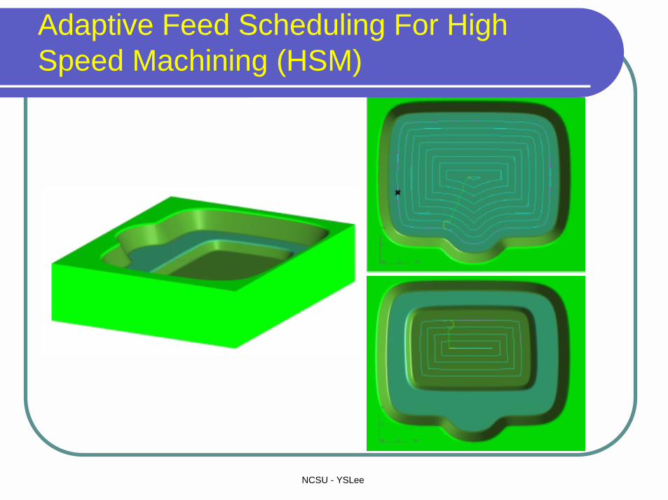
Adaptive Feed Scheduling For High Speed Machining (HSM)
NCSU - YSLee
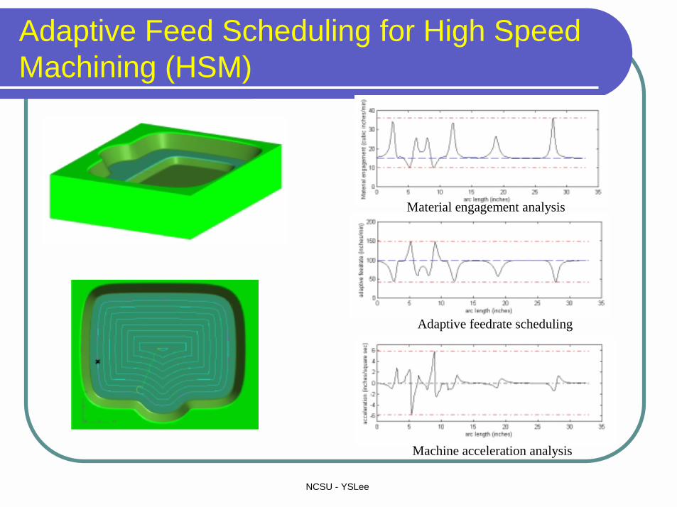
Adaptive Feed Scheduling for High Speed Machining (HSM)
Material engagement analysis
Adaptive feedrate scheduling
Machine acceleration analysis
NCSU - YSLee
Conclusions
� Modeling of complex surfaces for product development
� CAD/CAM for polyhedral model machining � 5-Axis machining of sculptured surfaces � High Speed Machining (HSM) can greatly
benefit manufacturing process by shortening the machining time and reducing the manufacturing cost.
� HSM CAD/CAM shares an increasing market in recent years and the trend will continue.

NCSU - YSLee
Thank you !!
Any Question ?