CAD - How Computer Can Aid Design? - engr.uvic.camech410/lectures/5c_FEA_ProMECHANICA.pdf ·...
38
CAD - How Computer Can Aid Design? At ti D i G ti • Automating Drawing Generation • Creating an Accurate 3D Model to Better Represent the Design and Allowing Easy Design Represent the Design and Allowing Easy Design Improvements • Evaluating How Good is the Design and Finding • Evaluating How Good is the Design and Finding Design Flaws – Analysis (FEA) • How to Improve the Design (where to start and • How to Improve the Design (where to start and what to change) – Sensitivity Analysis • Optimizing the Design - Optimization • Optimizing the Design - Optimization
Transcript of CAD - How Computer Can Aid Design? - engr.uvic.camech410/lectures/5c_FEA_ProMECHANICA.pdf ·...

CAD - How Computer Can Aid Design?
A t ti D i G ti• Automating Drawing Generation
• Creating an Accurate 3D Model to Better Represent the Design and Allowing Easy DesignRepresent the Design and Allowing Easy Design Improvements
• Evaluating How Good is the Design and Finding• Evaluating How Good is the Design and Finding Design Flaws – Analysis (FEA)
• How to Improve the Design (where to start and• How to Improve the Design (where to start and what to change) – Sensitivity Analysis
• Optimizing the Design - Optimization• Optimizing the Design - Optimization

Finite Element Analysis (FEA) – A UsefulFinite Element Analysis (FEA) – A Useful Tool for Evaluating Design Performance
(T i f Di i )(Topics of Discussion)
1. Use of FEA in CAD Environment, or Computer Aided Engineering – Pro/MECHANICA
2. Background of FEA Model Generation and gSolution Procedure
3. Capabilities and Limitations of FEA Tools
4. The Use of CAD Model and FEA Tools for Optimizing a Design

Finite Element Analysis (FEA) or FiniteFinite Element Analysis (FEA) or Finite Element Method (FEM)
The Finite Element Analysis (FEA) is a numerical method for solving problems ofnumerical method for solving problems of engineering and mathematical physics.
Useful for problems with complicated geometries loadings and material propertiesgeometries, loadings, and material propertieswhere analytical solutions can not be obtained.

Examples of Finite Element Analysis (FEA)Examples of Finite Element Analysis (FEA) or Finite Element Method (FEM)

I t d ti tI t d ti tIntroduction to Introduction to
Pro/MECHANICAPro/MECHANICA
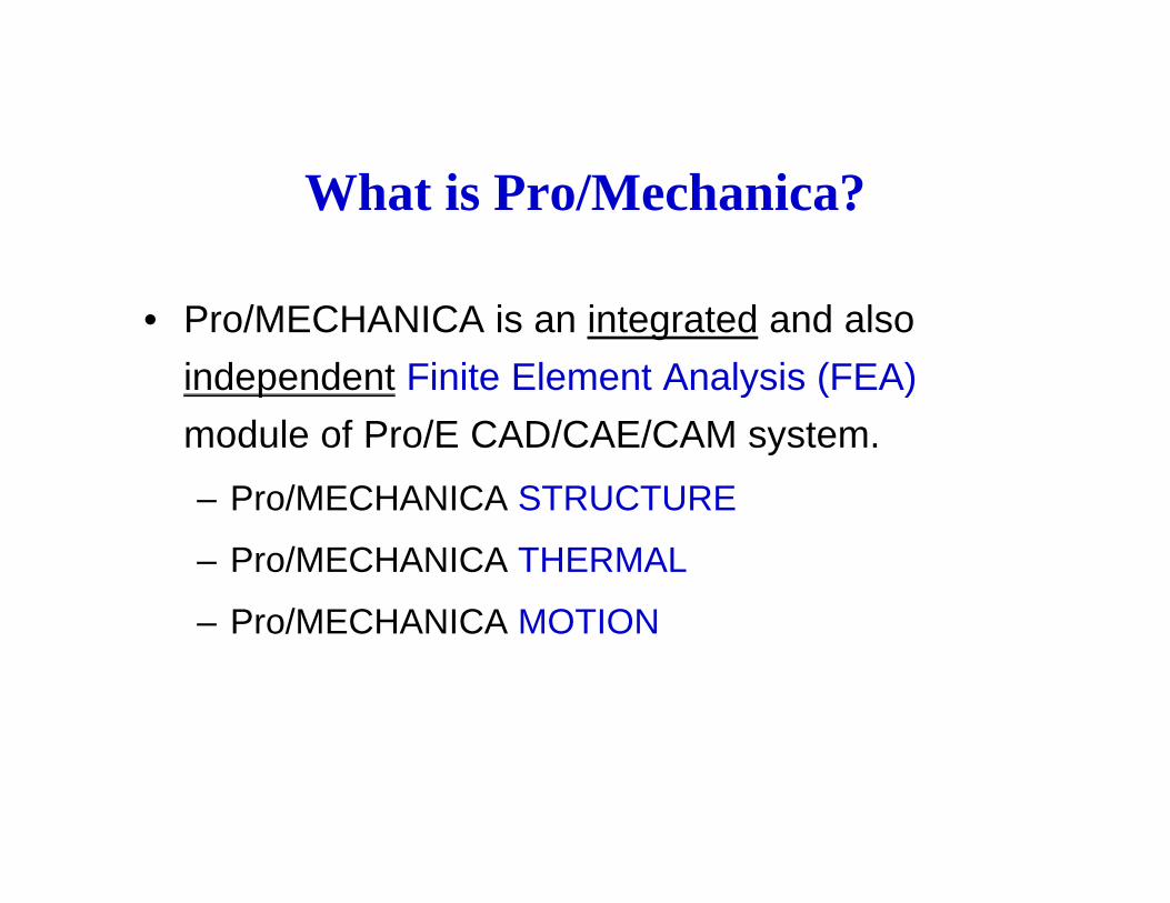
What is Pro/Mechanica?
• Pro/MECHANICA is an integrated and also independent Finite Element Analysis (FEA)p y ( )module of Pro/E CAD/CAE/CAM system. – Pro/MECHANICA STRUCTUREPro/MECHANICA STRUCTURE
– Pro/MECHANICA THERMAL
Pro/MECHANICA MOTION– Pro/MECHANICA MOTION

Start Pro/Mechanica from Pro/E


Pro/Mechanica StructurePro/Mechanica Structure
• Static, Buckling, Contact, and Pre-stress Analysesg y◊ Linear static stress analysis -- most structures, except non-
linearly elastic materials (such as rubber) and structures with large deformation (such as shells) (WF4 with nonlinear analysis capability)
◊ Bucking analysis -- stability of slim posts.
• Vibration◊ M d l l i ( d h d t l f i )◊ Modal analysis (mode shapes and natural frequencies) -
dynamic and vibration problems.
• Sensitivity Study (identify design parameters)• Optimization (identify the best values of design
parameters)

P /M h i Th lPro/Mechanica Thermal• Steady state and transient thermal modeling• Sensitivity study• Optimization
Pro/Mechanica MotionPro/Mechanica Motion3D static, kinetic, dynamic, and inverse dynamic analyses as well as interference checking

Operation ModesOperation Modes
• Integrated (within Pro/E)g ( )
– Easy design change– Cannot see mesh, less FEA
• Linked (Pro/E & Pro/M)
– Both interfaces; combination of the other two modesmodes
– Comparably more difficult to use • Independent (Pro/M)Independent (Pro/M)
– Strong FEA– Independent to Pro/E; hard to modifyp y

O ti M dOperation Modes

Two ApproximationTwo Approximation Methods
h l th element
l t
size
p element
order

General Process

FEA in Pro/MECHANICADiscretization
Real Word
Simplified(Idealized) Physical
Math. Model
Discretized(mesh) Model
Math. Modely
ModelModel

Difference between CAD Model andDifference between CAD Model and FEA Model
• A CAD model is to provide a detailed document for manufacturing
• A FEA model simply captures the rough geometry of the design and its loading conditions.◊ Eli i ti ll i t t d i d t il th t h i◊ Elimination all unimportant design details that have minor
effect on the results of FEA.◊ Use of part symmetry to dramatically reduce the size of the
d lmodel.◊ Elimination of uninterested portion of the design.- due to the limited computation power of today

Use of Model Symmetry to Reduce the y yComputation Complexity – ½ and ¼ Model

An Example

Process of Using Pro/M Structure
Stress Strain/Deformation

FEA Results

Convergence Methodsg
• Quick CheckNumerical method – iterative process
– Is not a convergence method since the model is run only for a single fixed (low) polynomial order.
– For error check (in defining the analysis problem)– The result should never be trusted
• Single Pass Adaptive– More than a Quick Check but less than a completeMore than a Quick Check, but less than a complete
convergence– Unless the model is very computationally intensive and/or is very
well behaved and known, avoid this method,
• Multi-Pass Adaptive– The ultimate in convergence analysis.
Base your final conclusions on the results obtained using this– Base your final conclusions on the results obtained using this convergence method.

Convergence Plots for the Maximum VonConvergence Plots for the Maximum Von Mises Stress and Strain Energy
NumericalProcess &
Converged Result

Tutorials for Pro/Engineer WildfireTutorials for Pro/Engineer Wildfire
7 Pro/Mechanica for Structural Analysis, y ,Sensitivity Analysis, and Design Optimization7.1 Prepare the Model7 2 St t P /MECHANICA7.2 Start Pro/MECHANICA7.3 Define the FEA model7.4 Run a static analysis7. u a stat c a a ys s7.5 Design parameter sensitivity study7.6 Design optimization
8 Pro/Mechanica – Standard Static Analysis8.1 Objectives8 2 Procedures8.2 Procedures

An ExampleAn Example
• Preparation of the Model– Base of a ViseBase of a Vise
size of the groove; why?

FEA Model from CAD Model
(a) A CAD Model (b) A Simplified CAD Model
(C) A FEA Model
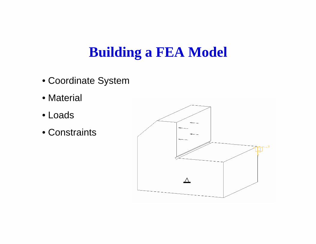
Building a FEA Model
• Coordinate System
• Material
• Loads
• Constraints
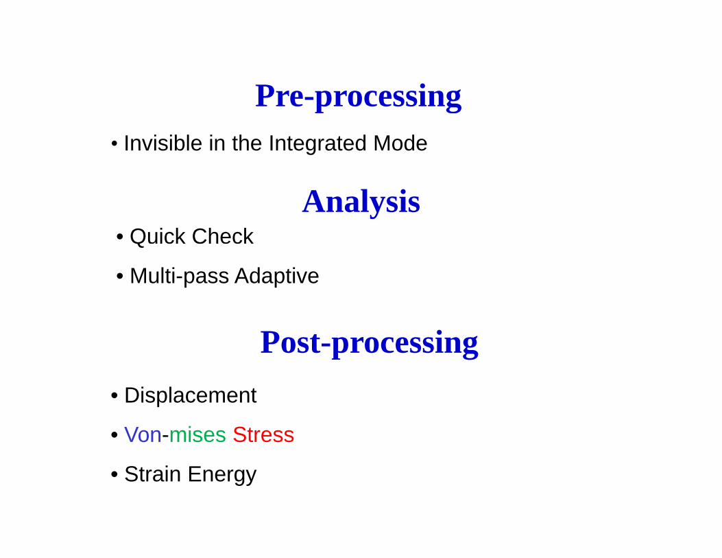
Pre-processingPre processing• Invisible in the Integrated Mode
Analysis• Quick CheckQ
• Multi-pass Adaptive
Post-processing• Displacement
• Von-mises Stress
• Strain Energy

Results
(a) Deformation (b) Von Mises Stress

Convergence CheckConvergence Check
max_stress_vmP Pass
strain_energyP PassP-Pass
Load: load1P-PassLoad: load1
14
12
10
max_stre
2.6
2.4
2.2
strain_e
10
8
6
ss_vm X 1E+
2.0
1.8
1.6
nergy X 1E-
654321
P Loop Pass
6
4
003
654321
P Loop Pass
1.4
1.2
003
(a) Von Mises (b) Strain Energy

Parameter Sensitivity StudyParameter Sensitivity Study
• Define a design parameter (groove size d)Define a design parameter (groove size, d)
d
• Define a design study
• Perform the study and plot displacement and stress

Sensitivity Study Different groove sizeSensitivity Study Different groove size causes different results
Every point represents one FEA run.
Max Displacement Max Stress
Variation of Design ObjectiveDesign Objective with Change of Design Variable
d d

Design OptimizationDesign Optimization
Objective: minimize the maximum stress in the structureObjective: minimize the maximum stress in the structureConstraints: maximum deformation of the L bracket
design variable
dvariable

Result of the OptimizationResult of the Optimization
Max Displacement Max Stress
Best groove size, : 0.13 (with minimum Maximum Stress)dEvery point represents one FEA run.

Different Optimization Result - IDifferent Optimization Result I (when large deformation is allowed)
d <= 0.18 d <= 0.18
d* = 0.13
Max Displacement Max Stress

Different Optimization Result - IIDifferent Optimization Result II(when large deformation is NOT allowed)
d <= 0.11 d <= 0.11
Limit on deformation
d* = 0.11
Limit on deformation
Max Displacement Max Stress

An Different Design Optimization with Two Design Variablesg p g
Objective: minimize the weight (mass) of the structureC t i t i l d d d f ti ll dConstraints: maximum load and deformation allowed
1. Define relations to control the model generation (two design t i th i d th th i th llparameters; one is the groove size and the other is the overall
fixture size.)Two design
i bl2. Specify ranges of variables, variables2. Specify ranges of variables, objective, and constraints
3. Perform the optimization (about 15 min )(about 15 min.)
4. Results plotting and convergence check

Pro/MECHANICA• Integrated Mode: The other two programs in Pro/M (Thermal and
Motion) are used for thermal analysis and motion analysis of ) y ymechanical systems, respectively.
Both of these two programs can pass information (for example temperature distributions) back to Structure in order to computetemperature distributions) back to Structure in order to compute the associated stresses.
• Design Tool: Pro/MECHANICA is a design tool since it will allow t i t di ll d i ti i tiparametric studies as well as design optimization.
• Limitations: Pro/M Structure has limited ability to handle non-linear problems (e.g. stress analysis involving non-linearly elastic
t i l l d f ti )material or large deformation). Problems involving large geometric deflections can be treated, as long as the stresses remain within the linearly elastic range for the materialthe material.

Quick QuestionsQ Q
• Why a CAD model should be simplified and unimportant portion of the model should be removed for FEA?
• Does a FEA model only include information of• Does a FEA model only include information of product geometry, loads and constraints?
• What are Pro/MECHANICA’s three convergence gmethods?
• What is the ideal index for FEA convergence check?• Can Pro/MECHANICA run independently to Pro/E?• What are the three necessary components of an
optimization problem?optimization problem?