
CACRC Composites Repair Analysis Final · May 2007 Composites Repair Analysis Spring 2007 CACRC...
31
May 2007 Composites Repair Analysis Spring 2007 CACRC Meeting Amsterdam, May 7-11, 2007 Spring 2007 CACRC Meeting Presented by Stephane Mahdi Airbus Engineering Composites Structural Analysis Department - ESAC
-
Upload
truonghanh -
Category
Documents
-
view
220 -
download
0
Transcript of CACRC Composites Repair Analysis Final · May 2007 Composites Repair Analysis Spring 2007 CACRC...
May 2007
Composites Repair AnalysisSpring 2007 CACRC MeetingAmsterdam, May 7-11, 2007
Spring 2007 CACRC Meeting
Presented by
Stephane MahdiAirbus Engineering Composites Structural Analysis Department - ESAC

May 2007Airbus - Composites Repair Analysis - Spring 2007 CACRC Meeting Page 2© A
IRB
US
TR
AN
SP
OR
T IN
TE
RN
AT
ION
AL
S.N
.C.
All
right
s re
serv
ed. C
onfid
entia
l and
pro
prie
tary
doc
umen
t.
Agenda
• Need for Repairs is a reality• Airbus Methodology for Repairs• Bolted and Bonded Repairs Calculation Methods
4Bolted Repairs4Bonded Repairs
• Summary and Conclusions
May 2007Airbus - Composites Repair Analysis - Spring 2007 CACRC Meeting Page 3© A
IRB
US
TR
AN
SP
OR
T IN
TE
RN
AT
ION
AL
S.N
.C.
All
right
s re
serv
ed. C
onfid
entia
l and
pro
prie
tary
doc
umen
t.
Need For Repairs is a Reality
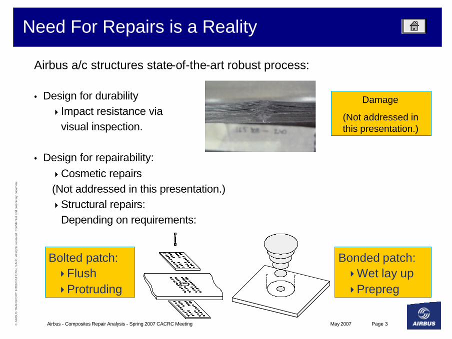
Bonded patch:4Wet lay up4Prepreg
Bolted patch:4Flush4Protruding
(b) Wet lay-up scarf patch repair
Airbus a/c structures state-of-the-art robust process:
• Design for durability4Impact resistance via
visual inspection.
• Design for repairability:4Cosmetic repairs(Not addressed in this presentation.)4Structural repairs:
Depending on requirements:
Damage
(Not addressed in this presentation.)
May 2007Airbus - Composites Repair Analysis - Spring 2007 CACRC Meeting Page 4© A
IRB
US
TR
AN
SP
OR
T IN
TE
RN
AT
ION
AL
S.N
.C.
All
right
s re
serv
ed. C
onfid
entia
l and
pro
prie
tary
doc
umen
t.
Airbus Methodology for Repairs
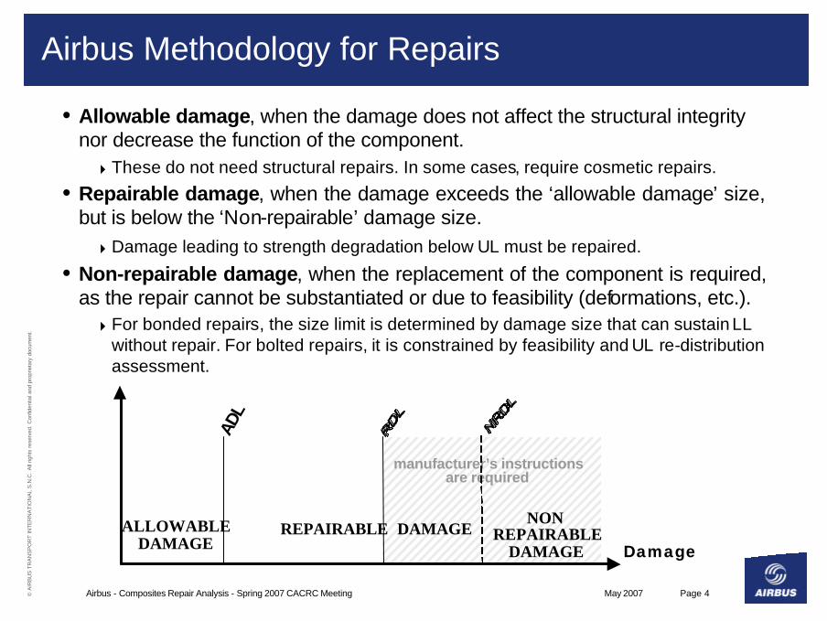
• Allowable damage, when the damage does not affect the structural integrity nor decrease the function of the component.
4These do not need structural repairs. In some cases, require cosmetic repairs.
• Repairable damage, when the damage exceeds the ‘allowable damage’ size, but is below the ‘Non-repairable’ damage size.
4Damage leading to strength degradation below UL must be repaired.
• Non-repairable damage, when the replacement of the component is required, as the repair cannot be substantiated or due to feasibility (deformations, etc.).
4For bonded repairs, the size limit is determined by damage size that can sustain LLwithout repair. For bolted repairs, it is constrained by feasibility and UL re-distribution assessment.
ALLOWABLEDAMAGE
REPAIRABLE DAMAGENON
REPAIRABLEDAMAGE
manufacturer’s instructionsare required
ADL
Damage
May 2007Airbus - Composites Repair Analysis - Spring 2007 CACRC Meeting Page 5© A
IRB
US
TR
AN
SP
OR
T IN
TE
RN
AT
ION
AL
S.N
.C.
All
right
s re
serv
ed. C
onfid
entia
l and
pro
prie
tary
doc
umen
t.
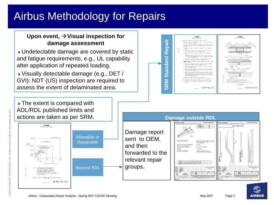
Upon event, àVisual inspection for damage assessment
4Undetectable damage are covered by static and fatigue requirements, e.g., UL capability after application of repeated loading.4Visually detectable damage (e.g., DET / GVI): NDT (US) inspection are required to assess the extent of delaminated area.
Damage report sent to OEM, and then forwarded to the relevant repair groups.
Damage outside RDL
Beyond RDLS
RM
Sta
ndar
d R
epai
r
Allowable or Repairable
Airbus Methodology for Repairs
4The extent is compared with ADL/RDL published limits and actions are taken as per SRM.
May 2007Airbus - Composites Repair Analysis - Spring 2007 CACRC Meeting Page 6© A
IRB
US
TR
AN
SP
OR
T IN
TE
RN
AT
ION
AL
S.N
.C.
All
right
s re
serv
ed. C
onfid
entia
l and
pro
prie
tary
doc
umen
t.
Airbus Methodology for Repairs
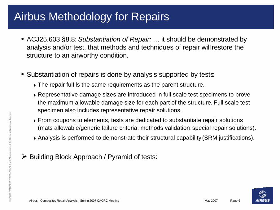
• ACJ25.603 §8.8: Substantiation of Repair: … it should be demonstrated by analysis and/or test, that methods and techniques of repair will restore the structure to an airworthy condition.
• Substantiation of repairs is done by analysis supported by tests:4The repair fulfils the same requirements as the parent structure.
4Representative damage sizes are introduced in full scale test specimens to prove the maximum allowable damage size for each part of the structure. Full scale test specimen also includes representative repair solutions.
4From coupons to elements, tests are dedicated to substantiate repair solutions (mats allowable/generic failure criteria, methods validation, special repair solutions).
4Analysis is performed to demonstrate their structural capability (SRM justifications).
Ø Building Block Approach / Pyramid of tests:

May 2007Airbus - Composites Repair Analysis - Spring 2007 CACRC Meeting Page 7© A
IRB
US
TR
AN
SP
OR
T IN
TE
RN
AT
ION
AL
S.N
.C.
All
right
s re
serv
ed. C
onfid
entia
l and
pro
prie
tary
doc
umen
t.
Airbus Methodology for Repairs
• Building Block Approach / Pyramid of tests:
200
100
1000
300
100
Methodology & Computing validation
• Validation against coupon and smaller specimen allowables• At detail level, ‘B’ values are determined.
Final validation•Validation and exploitation on full scale or component tests
Coupon/Qualification
Stress allowable programme
Details
Sub-components
Components
- Full-scale
No
n -G
ener
ic s
pec
imen
sG
ener
ic
spec
imen
s
Definition of generic allowables set• Statistical treatment large and small populations ‘B’ values• In general 1 typical feature per specimen (hole, impact damage, lay-up..)
Elements

May 2007Airbus - Composites Repair Analysis - Spring 2007 CACRC Meeting Page 8© A
IRB
US
TR
AN
SP
OR
T IN
TE
RN
AT
ION
AL
S.N
.C.
All
right
s re
serv
ed. C
onfid
entia
l and
pro
prie
tary
doc
umen
t.
Airbus Methodology for Repairs
e.g.,CompositeWing Box
May 2007Airbus - Composites Repair Analysis - Spring 2007 CACRC Meeting Page 9© A
IRB
US
TR
AN
SP
OR
T IN
TE
RN
AT
ION
AL
S.N
.C.
All
right
s re
serv
ed. C
onfid
entia
l and
pro
prie
tary
doc
umen
t.
Airbus Methodology for Repairs
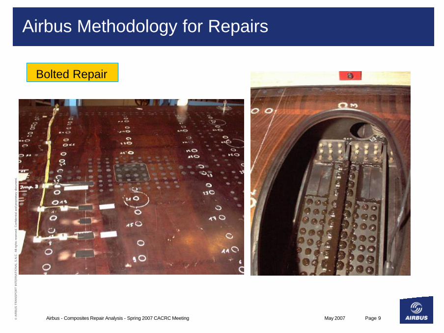
Bolted Repair

May 2007Airbus - Composites Repair Analysis - Spring 2007 CACRC Meeting Page 10© A
IRB
US
TR
AN
SP
OR
T IN
TE
RN
AT
ION
AL
S.N
.C.
All
right
s re
serv
ed. C
onfid
entia
l and
pro
prie
tary
doc
umen
t.
Airbus Methodology for Repairs
• Example of a possible test sequence:
Introduction of Manufacturing defects, BVID, AD & repairs
Tested to UL at worst environmental condition
Introduction of LVID
Tested to LL at worst environmental condition
Fatigue phase DT phase
May 2007Airbus - Composites Repair Analysis - Spring 2007 CACRC Meeting Page 11© A
IRB
US
TR
AN
SP
OR
T IN
TE
RN
AT
ION
AL
S.N
.C.
All
right
s re
serv
ed. C
onfid
entia
l and
pro
prie
tary
doc
umen
t.
Airbus Methodology for Repairs
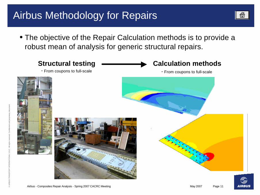
• The objective of the Repair Calculation methods is to provide a robust mean of analysis for generic structural repairs.
Structural testing- From coupons to full-scale
Calculation methods- From coupons to full-scale

May 2007Airbus - Composites Repair Analysis - Spring 2007 CACRC Meeting Page 12© A
IRB
US
TR
AN
SP
OR
T IN
TE
RN
AT
ION
AL
S.N
.C.
All
right
s re
serv
ed. C
onfid
entia
l and
pro
prie
tary
doc
umen
t.
Bolted and Bonded Repairs Calculation Methods
Damage to a stiffener foot
Damage to the Bay
Single-/Double-laprepair to the Bay
Filledhole
Double-lap repairto a stiffener foot
Double-lap repair to a stiffener webDouble-lap Repairof a through-through
damage
Damage to a stiffener web
Through-through damage(a) Definition of potential damage sites
(b) Definition of corresponding repair types
• The objective of the repair calculation methods is to provide a robust mean of analysis for generic structural repairs.4Assumption about damage sites, and typical corresponding
bolted repairs:
May 2007Airbus - Composites Repair Analysis - Spring 2007 CACRC Meeting Page 13© A
IRB
US
TR
AN
SP
OR
T IN
TE
RN
AT
ION
AL
S.N
.C.
All
right
s re
serv
ed. C
onfid
entia
l and
pro
prie
tary
doc
umen
t.
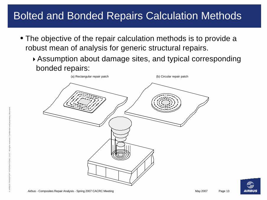
Bolted and Bonded Repairs Calculation Methods
(a) Rectangular repair patch (b) Circular repair patch
• The objective of the repair calculation methods is to provide a robust mean of analysis for generic structural repairs.4Assumption about damage sites, and typical corresponding
bonded repairs:

May 2007Airbus - Composites Repair Analysis - Spring 2007 CACRC Meeting Page 14© A
IRB
US
TR
AN
SP
OR
T IN
TE
RN
AT
ION
AL
S.N
.C.
All
right
s re
serv
ed. C
onfid
entia
l and
pro
prie
tary
doc
umen
t.
Bolted and Bonded Repairs Calculation Methods
• Repairs calculation methods are a two-step process:
1. Internal load transfer calculation,a. Quick sizing approachb. Advanced sizing approach
2. Stress process.

May 2007Airbus - Composites Repair Analysis - Spring 2007 CACRC Meeting Page 15© A
IRB
US
TR
AN
SP
OR
T IN
TE
RN
AT
ION
AL
S.N
.C.
All
right
s re
serv
ed. C
onfid
entia
l and
pro
prie
tary
doc
umen
t.
Bolted
Bolted and Bonded Repairs Calculation Methods
1. Internal load transfer calculation:a. Quick Sizing: 1D analytical approach
– The calculation of the load transfer is done analytically,– Repair patch size effect may affect the internal load redistribution.
b. Advanced sizing: 2D parametric FE approach– Fast and robust parametric-FE, transparent to the user.– Applicable to various repair types and representative of structural
elements. Influence of stiffeners, repair patch geometry may be included,
– Directly applicable to 2D stress fields.
Bonded

May 2007Airbus - Composites Repair Analysis - Spring 2007 CACRC Meeting Page 16© A
IRB
US
TR
AN
SP
OR
T IN
TE
RN
AT
ION
AL
S.N
.C.
All
right
s re
serv
ed. C
onfid
entia
l and
pro
prie
tary
doc
umen
t.
Bolted and Bonded Repairs Calculation Methods
2. The stress process is done based on the calculated internal loads.
Bolted Bonded

May 2007Airbus - Composites Repair Analysis - Spring 2007 CACRC Meeting Page 17© A
IRB
US
TR
AN
SP
OR
T IN
TE
RN
AT
ION
AL
S.N
.C.
All
right
s re
serv
ed. C
onfid
entia
l and
pro
prie
tary
doc
umen
t.
Bolted Repairs Internal Load CalculationQuick Sizing
k*d
The fasteners are analysed perfastener rows
• The analysis is done on a fastener pitch.(The repair efficiencyis taken into account.)
• A load transfer calculationis then done:
35% 30% 35%
May 2007Airbus - Composites Repair Analysis - Spring 2007 CACRC Meeting Page 18© A
IRB
US
TR
AN
SP
OR
T IN
TE
RN
AT
ION
AL
S.N
.C.
All
right
s re
serv
ed. C
onfid
entia
l and
pro
prie
tary
doc
umen
t.
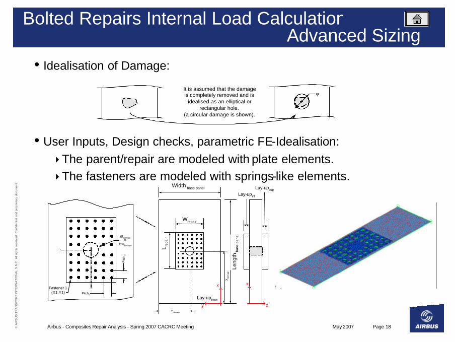
Bolted Repairs Internal Load CalculationAdvanced Sizing
It is assumed that the damageis completely removed and is
idealised as an elliptical orrectangular hole.
(a circular damage is shown).
φ
• Idealisation of Damage:
• User Inputs, Design checks, parametric FE-Idealisation:4The parent/repair are modeled with plate elements.4The fasteners are modeled with springs-like elements.
Leng
th b
ase
pane
l
L rep
air
Wrepair
Lay-upsup
x
y
Lay-upbase
Øldamage=
Øwd amage
Pitchx
Width base panel
z
x
Lay-up inf
Pitc
hy
Ydamage
Xda
mag
e
Fastener 1(X1,Y1)
May 2007Airbus - Composites Repair Analysis - Spring 2007 CACRC Meeting Page 19© A
IRB
US
TR
AN
SP
OR
T IN
TE
RN
AT
ION
AL
S.N
.C.
All
right
s re
serv
ed. C
onfid
entia
l and
pro
prie
tary
doc
umen
t.
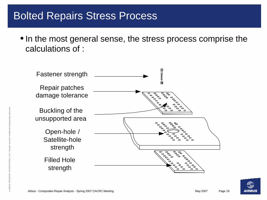
Bolted Repairs Stress Process
• In the most general sense, the stress process comprise the calculations of :
Open-hole /Satellite-hole
strength
Repair patchesdamage tolerance
Fastener strength
Buckling of theunsupported area
Filled Holestrength
May 2007Airbus - Composites Repair Analysis - Spring 2007 CACRC Meeting Page 20© A
IRB
US
TR
AN
SP
OR
T IN
TE
RN
AT
ION
AL
S.N
.C.
All
right
s re
serv
ed. C
onfid
entia
l and
pro
prie
tary
doc
umen
t.
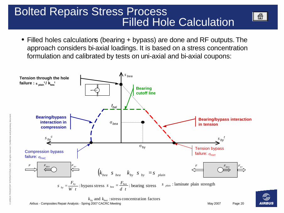
Bolted Repairs Stress ProcessFilled Hole Calculation
• Filled holes calculations (bearing + bypass) are done and RF outputs. The approach considers bi-axial loadings. It is based on a stress concentration formulation and calibrated by tests on uni-axial and bi-axial coupons:
( ) plainbybybeabea kk σσσ =⋅+⋅
stress bypass:tW
Fbyby ⋅
=σ stress bearing:td
Fbeabea ⋅
=σ strengthplain laminate:plainσ
factorsion concentrat stress: and beaby kk
σbyt
Compression bypass failure: σFHC
Bearing cutoff line
Bearing/bypass interaction in compression
Bearing/bypass interaction in tension
σbea
σbyc
Tension bypass failure: σFHT
fbal
Tension through the hole failure : σplain
t / kbeat
σby
σbea
BEAF BYFF
BEAF BYFF

May 2007Airbus - Composites Repair Analysis - Spring 2007 CACRC Meeting Page 21© A
IRB
US
TR
AN
SP
OR
T IN
TE
RN
AT
ION
AL
S.N
.C.
All
right
s re
serv
ed. C
onfid
entia
l and
pro
prie
tary
doc
umen
t.
Bonded Repairs Internal Load CalculationQuick & Advanced Sizings
A-A
(b) 1D Analytical repairpatch to a monolithic panel
(a) 2D Parametric-FE (here circular)repair patch to a monolithic panel
A
A
NX
Ny
NXy
NX
NXy
4A 1D analytical approach, representative of a cross-section of a repaired panel,
4A 2D parametric FE approach.

May 2007Airbus - Composites Repair Analysis - Spring 2007 CACRC Meeting Page 22© A
IRB
US
TR
AN
SP
OR
T IN
TE
RN
AT
ION
AL
S.N
.C.
All
right
s re
serv
ed. C
onfid
entia
l and
pro
prie
tary
doc
umen
t.
Bonded Repairs Stress Process
• In the most general sense, the stress process comprise the calculations of :
(b) Wet lay-up scarf repair(a) Adhesively bonded scarf repair
Adhesive filmPre-preg Impregnated wet
lay-up repair
Base MaterialPlain Strength
Calculation
Repair PatchPlain Strength
Calculation
Damaged HoleCalculation
Adhesive CohesiveStrength Calculation
(at each step)
DamageToleranceCalculation

May 2007Airbus - Composites Repair Analysis - Spring 2007 CACRC Meeting Page 23© A
IRB
US
TR
AN
SP
OR
T IN
TE
RN
AT
ION
AL
S.N
.C.
All
right
s re
serv
ed. C
onfid
entia
l and
pro
prie
tary
doc
umen
t.
Bonded Repairs Stress Process Bond Strength Calculation
• Building block approach is used for static and fatigue validation.• Strong experience built on good design practises to alleviate peel
stresses (PDO, SRO, etc.).• The cohesive bond strength calculation is based on:
4Bondline through-thickness averaged properties,4Strength calibrated from tests with theoretical bondline thickness.
• The calculation is based on well controlled M&P parameters that are crucial for interfacial and cohesive bond properties.
• Linear and NL bond material properties are established:
• The allowable are defined takinginto account durability parameters:
0
Shear Strain, γ
γay γa
τay
γALL
She
ar
Str
ess
, τ
τALL
γaf
τaf
γaly
τaly
May 2007Airbus - Composites Repair Analysis - Spring 2007 CACRC Meeting Page 24© A
IRB
US
TR
AN
SP
OR
T IN
TE
RN
AT
ION
AL
S.N
.C.
All
right
s re
serv
ed. C
onfid
entia
l and
pro
prie
tary
doc
umen
t.
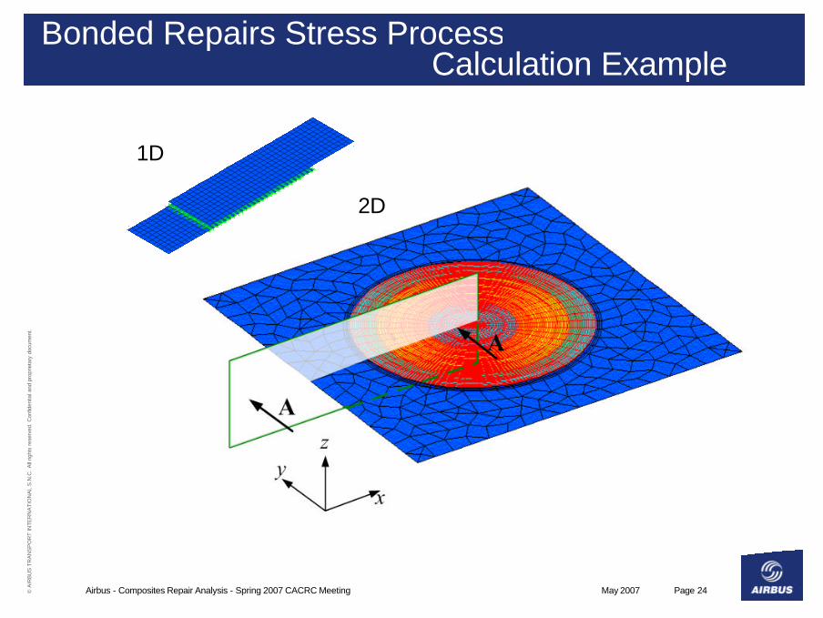
Bonded Repairs Stress ProcessCalculation Example
1D
2D
May 2007Airbus - Composites Repair Analysis - Spring 2007 CACRC Meeting Page 25© A
IRB
US
TR
AN
SP
OR
T IN
TE
RN
AT
ION
AL
S.N
.C.
All
right
s re
serv
ed. C
onfid
entia
l and
pro
prie
tary
doc
umen
t.
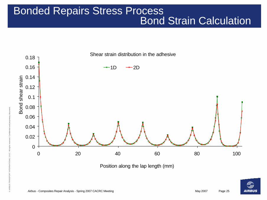
Bonded Repairs Stress ProcessBond Strain Calculation
Shear strain distribution in the adhesive
0
0.02
0.04
0.06
0.08
0.1
0.12
0.14
0.16
0.18
0 20 40 60 80 100
Position along the lap length (mm)
Bon
d sh
ear
stra
in
1D 2D
May 2007Airbus - Composites Repair Analysis - Spring 2007 CACRC Meeting Page 26© A
IRB
US
TR
AN
SP
OR
T IN
TE
RN
AT
ION
AL
S.N
.C.
All
right
s re
serv
ed. C
onfid
entia
l and
pro
prie
tary
doc
umen
t.
Bonded Repairs Stress ProcessCurrent Developments
• Development of strength of materials approach, taking into account bond deformation and fracture and implementation of shear/peel iterative criteria.
• Development of fracture mechanics / damage mechanics approaches for the assessment of impact damages / delamination.
• Airbus understanding of regulatory requirements restricts introduction of bonded repairs on composite primary structures.
• Innovative NDI/SHM techniques are being looked at for introducing bonded repairs on PSE.
May 2007Airbus - Composites Repair Analysis - Spring 2007 CACRC Meeting Page 27© A
IRB
US
TR
AN
SP
OR
T IN
TE
RN
AT
ION
AL
S.N
.C.
All
right
s re
serv
ed. C
onfid
entia
l and
pro
prie
tary
doc
umen
t.
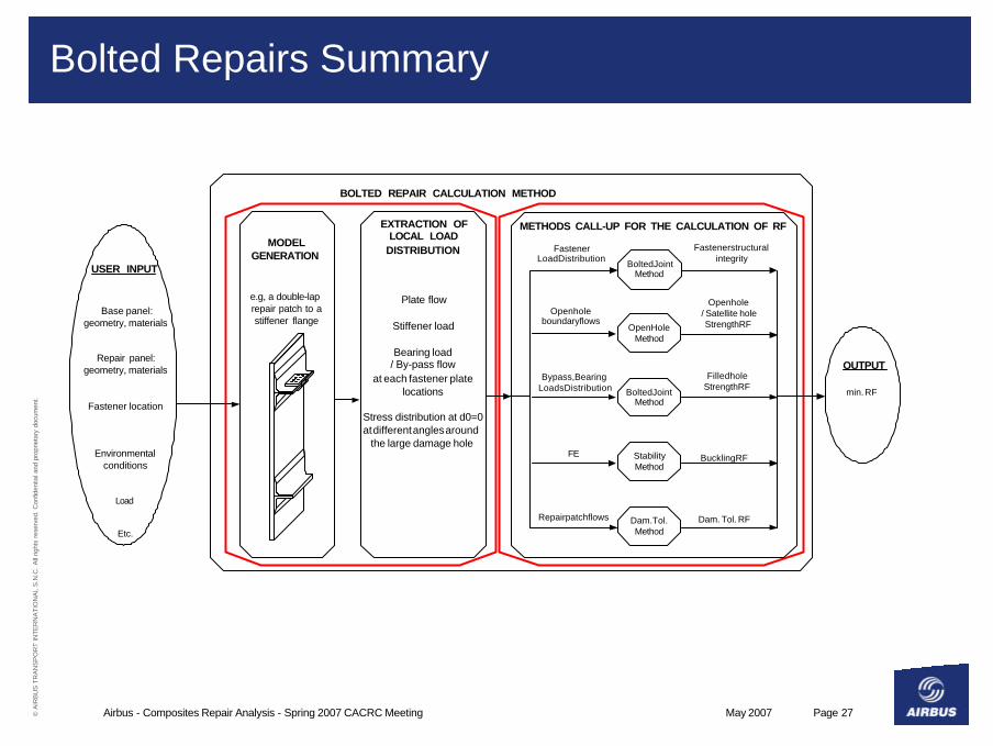
Bolted Repairs Summary
Open HoleMethod
Bypass, BearingLoads Distribution
Bolted JointMethod
FastenerLoad Distribution
Base panel:geometry, materials
Repair panel:geometry, materials
Fastener location
Environmentalconditions
Load
Etc.
Plate flow
Stiffener load
Bearing load/ By-pass flow
at each fastener platelocations
Stress distribution at d0=0at different angles around
the large damage hole
Open holeboundary flows
min. RF
EXTRACTION OFLOCAL LOAD
DISTRIBUTION
USER INPUT
MODELGENERATION
e.g, a double-laprepair patch to astiffener flange
METHODS CALL-UP FOR THE CALCULATION OF RF
Bolted JointMethod
StabilityMethod
FE
Fastener structuralintegrity
Open hole / Satellite hole
Strength RF
Filled holeStrength RF
OUTPUT
BOLTED REPAIR CALCULATION METHOD
Buckling RF
Dam. Tol.Method
Repair patch flows Dam. Tol. RF
May 2007Airbus - Composites Repair Analysis - Spring 2007 CACRC Meeting Page 28© A
IRB
US
TR
AN
SP
OR
T IN
TE
RN
AT
ION
AL
S.N
.C.
All
right
s re
serv
ed. C
onfid
entia
l and
pro
prie
tary
doc
umen
t.
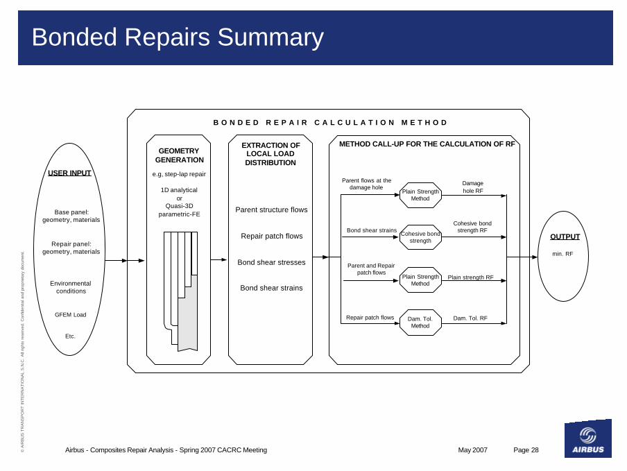
Bonded Repairs Summary
Plain StrengthMethod
Bond shear strains
Base panel:geometry, materials
Repair panel:geometry, materials
Environmentalconditions
GFEM Load
Etc.
Parent structure flows
Repair patch flows
Bond shear stresses
Bond shear strains
min. RF
EXTRACTION OFLOCAL LOADDISTRIBUTION
USER INPUT
GEOMETRYGENERATION
e.g, step-lap repair
1D analyticalor
Quasi-3Dparametric-FE
METHOD CALL-UP FOR THE CALCULATION OF RF
Cohesive bondstrength
Plain StrengthMethod
Parent and Repairpatch flows
Damagehole RF
Cohesive bondstrength RF
OUTPUT
B O N D E D R E P A I R C A L C U L A T I O N M E T H O D
Plain strength RF
Dam. Tol.Method
Repair patch flows Dam. Tol. RF
Parent flows at thedamage hole

May 2007Airbus - Composites Repair Analysis - Spring 2007 CACRC Meeting Page 29© A
IRB
US
TR
AN
SP
OR
T IN
TE
RN
AT
ION
AL
S.N
.C.
All
right
s re
serv
ed. C
onfid
entia
l and
pro
prie
tary
doc
umen
t.
Bonded and Bolted Repairs Summary
• Airbus repair methodology ensures proper maintainability by considering repair philosophy at the design stage.
• Design for repairable structures:4Criteria for robustness - economical and structural:
– ADL/RDL are defined taking into account service history,– Structures are inspectable and repairable using common
techniques,4Standardised structural repairs (SRM):
– Materials and allowable are based on controlled, qualified, materials and processes satisfying regulatory requirements and offering long-term reliable usage,
– Design and calculation criteria are defined taking into account robustness and durability,
May 2007Airbus - Composites Repair Analysis - Spring 2007 CACRC Meeting Page 30© A
IRB
US
TR
AN
SP
OR
T IN
TE
RN
AT
ION
AL
S.N
.C.
All
right
s re
serv
ed. C
onfid
entia
l and
pro
prie
tary
doc
umen
t.
Composites Repair Analysis
Thank you - Questions ?
May 2007Airbus - Composites Repair Analysis - Spring 2007 CACRC Meeting Page 31© A
IRB
US
TR
AN
SP
OR
T IN
TE
RN
AT
ION
AL
S.N
.C.
All
right
s re
serv
ed. C
onfid
entia
l and
pro
prie
tary
doc
umen
t.
© AIRBUS S.A.S. All rights reserved. Confidential and proprietary document.
This document and all information contained herein is the sole property of AIRBUS S.A.S.. No intellectual property rights are granted by the delivery of this document or the disclosure of its content. This document shall not be reproduced or disclosed to a third party without the express written consent of AIRBUS S.A.S. This document and its content shall not be used for any purpose other than that for which it is supplied.
The statements made herein do not constitute an offer. They are based on the mentioned assumptions and are expressed in good faith. Where the supporting grounds for these statements are not shown, AIRBUS S.A.S. will be pleased to explain the basis thereof.
AIRBUS, its logo, A300, A310, A318, A319, A320, A321, A330, A340, A350, A380, A400M are registered trademarks.


![CACRC Comittee Information[1]](https://static.fdocuments.us/doc/165x107/55cf97f2550346d033949bfc/cacrc-comittee-information1.jpg)