Cabling Specifications - · PDF fileA-6 Cisco AS5350XM and Cisco AS5400XM Universal Gateways...
14
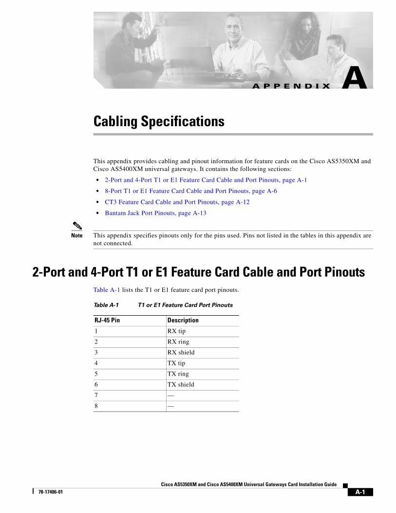
A-1 Cisco AS5350XM and Cisco AS5400XM Universal Gateways Card Installation Guide 78-17406-01 APPENDIX A Cabling Specifications This appendix provides cabling and pinout information for feature cards on the Cisco AS5350XM and Cisco AS5400XM universal gateways. It contains the following sections: • 2-Port and 4-Port T1 or E1 Feature Card Cable and Port Pinouts, page A-1 • 8-Port T1 or E1 Feature Card Cable and Port Pinouts, page A-6 • CT3 Feature Card Cable and Port Pinouts, page A-12 • Bantam Jack Port Pinouts, page A-13 Note This appendix specifies pinouts only for the pins used. Pins not listed in the tables in this appendix are not connected. 2-Port and 4-Port T1 or E1 Feature Card Cable and Port Pinouts Table A-1 lists the T1 or E1 feature card port pinouts. Table A-1 T1 or E1 Feature Card Port Pinouts RJ-45 Pin Description 1 RX tip 2 RX ring 3 RX shield 4 TX tip 5 TX ring 6 TX shield 7 — 8 —
-
Upload
nguyenkiet -
Category
Documents
-
view
222 -
download
5
Transcript of Cabling Specifications - · PDF fileA-6 Cisco AS5350XM and Cisco AS5400XM Universal Gateways...
Cisco AS5350XM and Cisco AS5400XM Univ78-17406-01
A P P E N D I X A
Cabling SpecificationsThis appendix provides cabling and pinout information for feature cards on the Cisco AS5350XM and Cisco AS5400XM universal gateways. It contains the following sections:
• 2-Port and 4-Port T1 or E1 Feature Card Cable and Port Pinouts, page A-1
• 8-Port T1 or E1 Feature Card Cable and Port Pinouts, page A-6
• CT3 Feature Card Cable and Port Pinouts, page A-12
• Bantam Jack Port Pinouts, page A-13
Note This appendix specifies pinouts only for the pins used. Pins not listed in the tables in this appendix are not connected.
2-Port and 4-Port T1 or E1 Feature Card Cable and Port PinoutsTable A-1 lists the T1 or E1 feature card port pinouts.
Table A-1 T1 or E1 Feature Card Port Pinouts
RJ-45 Pin Description
1 RX tip
2 RX ring
3 RX shield
4 TX tip
5 TX ring
6 TX shield
7 —
8 —
A-1ersal Gateways Card Installation Guide
Appendix A Cabling Specifications2-Port and 4-Port T1 or E1 Feature Card Cable and Port Pinouts
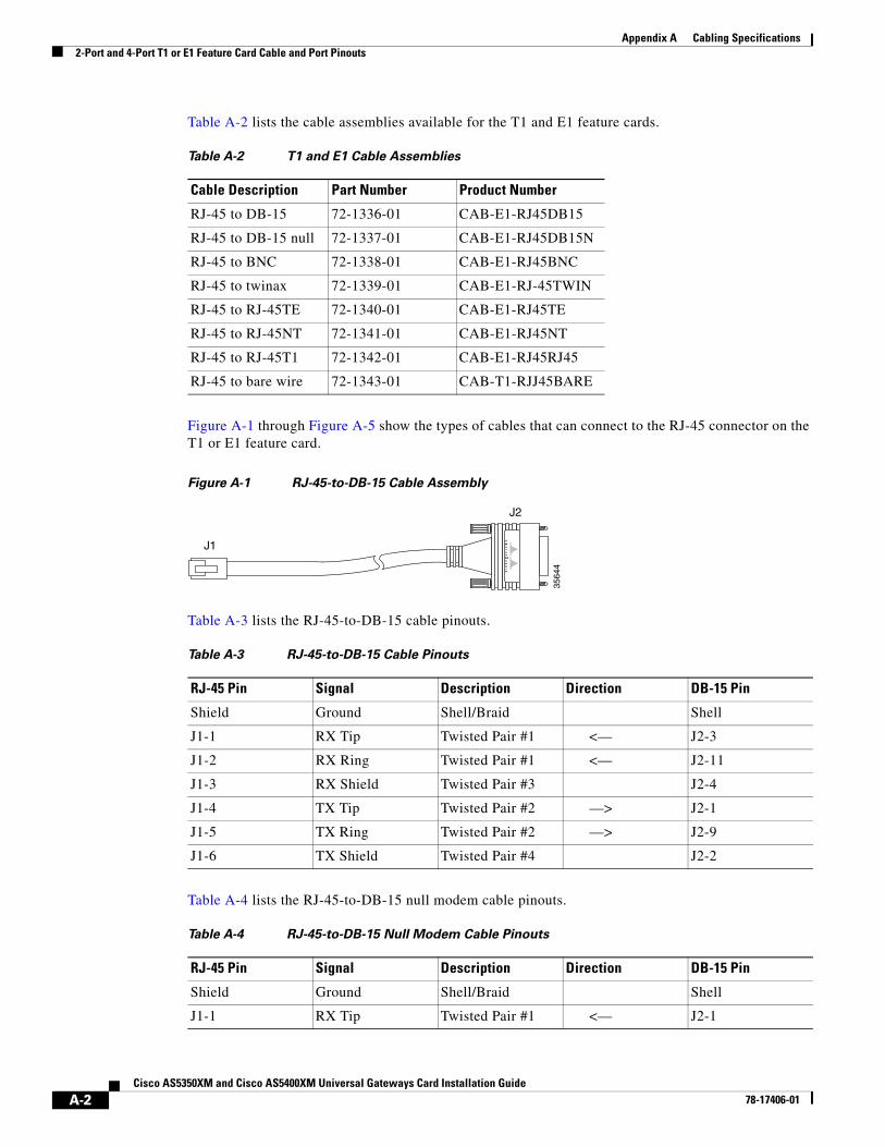
Table A-2 lists the cable assemblies available for the T1 and E1 feature cards.
Figure A-1 through Figure A-5 show the types of cables that can connect to the RJ-45 connector on the T1 or E1 feature card.
Figure A-1 RJ-45-to-DB-15 Cable Assembly
Table A-3 lists the RJ-45-to-DB-15 cable pinouts.
Table A-4 lists the RJ-45-to-DB-15 null modem cable pinouts.
Table A-2 T1 and E1 Cable Assemblies
Cable Description Part Number Product Number
RJ-45 to DB-15 72-1336-01 CAB-E1-RJ45DB15
RJ-45 to DB-15 null 72-1337-01 CAB-E1-RJ45DB15N
RJ-45 to BNC 72-1338-01 CAB-E1-RJ45BNC
RJ-45 to twinax 72-1339-01 CAB-E1-RJ-45TWIN
RJ-45 to RJ-45TE 72-1340-01 CAB-E1-RJ45TE
RJ-45 to RJ-45NT 72-1341-01 CAB-E1-RJ45NT
RJ-45 to RJ-45T1 72-1342-01 CAB-E1-RJ45RJ45
RJ-45 to bare wire 72-1343-01 CAB-T1-RJJ45BARE
3564
4J1
J2
Table A-3 RJ-45-to-DB-15 Cable Pinouts
RJ-45 Pin Signal Description Direction DB-15 Pin
Shield Ground Shell/Braid Shell
J1-1 RX Tip Twisted Pair #1 <— J2-3
J1-2 RX Ring Twisted Pair #1 <— J2-11
J1-3 RX Shield Twisted Pair #3 J2-4
J1-4 TX Tip Twisted Pair #2 —> J2-1
J1-5 TX Ring Twisted Pair #2 —> J2-9
J1-6 TX Shield Twisted Pair #4 J2-2
Table A-4 RJ-45-to-DB-15 Null Modem Cable Pinouts
RJ-45 Pin Signal Description Direction DB-15 Pin
Shield Ground Shell/Braid Shell
J1-1 RX Tip Twisted Pair #1 <— J2-1
A-2Cisco AS5350XM and Cisco AS5400XM Universal Gateways Card Installation Guide
78-17406-01
Appendix A Cabling Specifications2-Port and 4-Port T1 or E1 Feature Card Cable and Port Pinouts
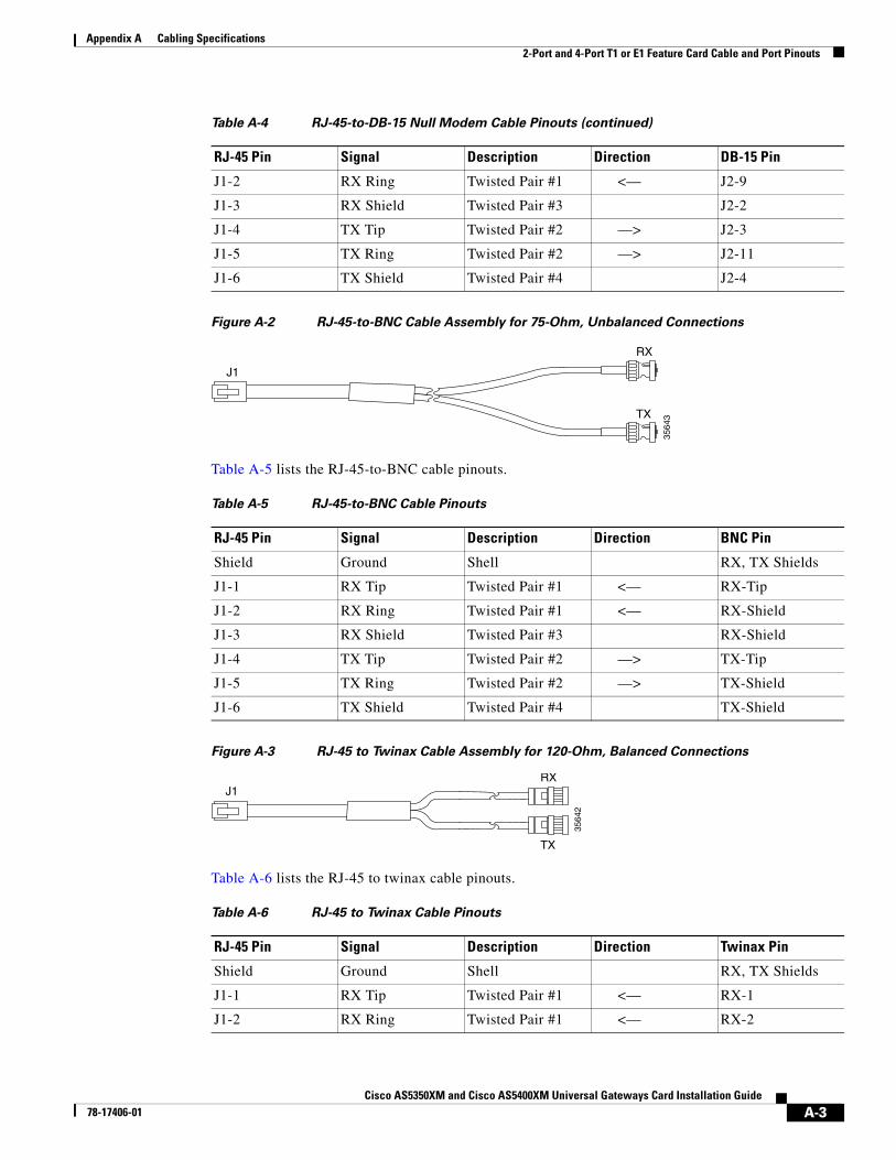
Figure A-2 RJ-45-to-BNC Cable Assembly for 75-Ohm, Unbalanced Connections
Table A-5 lists the RJ-45-to-BNC cable pinouts.
Figure A-3 RJ-45 to Twinax Cable Assembly for 120-Ohm, Balanced Connections
Table A-6 lists the RJ-45 to twinax cable pinouts.
J1-2 RX Ring Twisted Pair #1 <— J2-9
J1-3 RX Shield Twisted Pair #3 J2-2
J1-4 TX Tip Twisted Pair #2 —> J2-3
J1-5 TX Ring Twisted Pair #2 —> J2-11
J1-6 TX Shield Twisted Pair #4 J2-4
Table A-4 RJ-45-to-DB-15 Null Modem Cable Pinouts (continued)
RJ-45 Pin Signal Description Direction DB-15 Pin
3564
3
J1
RX
TX
Table A-5 RJ-45-to-BNC Cable Pinouts
RJ-45 Pin Signal Description Direction BNC Pin
Shield Ground Shell RX, TX Shields
J1-1 RX Tip Twisted Pair #1 <— RX-Tip
J1-2 RX Ring Twisted Pair #1 <— RX-Shield
J1-3 RX Shield Twisted Pair #3 RX-Shield
J1-4 TX Tip Twisted Pair #2 —> TX-Tip
J1-5 TX Ring Twisted Pair #2 —> TX-Shield
J1-6 TX Shield Twisted Pair #4 TX-Shield
3564
2
J1RX
TX
Table A-6 RJ-45 to Twinax Cable Pinouts
RJ-45 Pin Signal Description Direction Twinax Pin
Shield Ground Shell RX, TX Shields
J1-1 RX Tip Twisted Pair #1 <— RX-1
J1-2 RX Ring Twisted Pair #1 <— RX-2
A-3Cisco AS5350XM and Cisco AS5400XM Universal Gateways Card Installation Guide
78-17406-01
Appendix A Cabling Specifications2-Port and 4-Port T1 or E1 Feature Card Cable and Port Pinouts
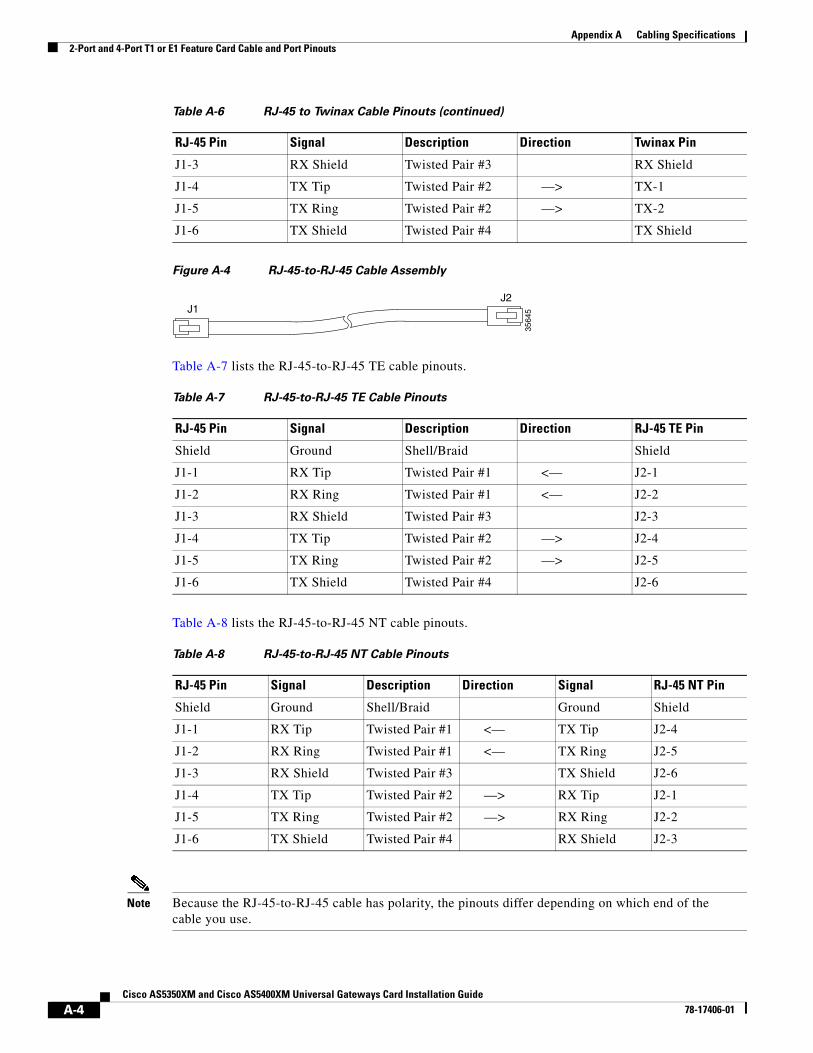
Figure A-4 RJ-45-to-RJ-45 Cable Assembly
Table A-7 lists the RJ-45-to-RJ-45 TE cable pinouts.
Table A-8 lists the RJ-45-to-RJ-45 NT cable pinouts.
Note Because the RJ-45-to-RJ-45 cable has polarity, the pinouts differ depending on which end of the cable you use.
J1-3 RX Shield Twisted Pair #3 RX Shield
J1-4 TX Tip Twisted Pair #2 —> TX-1
J1-5 TX Ring Twisted Pair #2 —> TX-2
J1-6 TX Shield Twisted Pair #4 TX Shield
Table A-6 RJ-45 to Twinax Cable Pinouts (continued)
RJ-45 Pin Signal Description Direction Twinax Pin
3564
5J1J2
Table A-7 RJ-45-to-RJ-45 TE Cable Pinouts
RJ-45 Pin Signal Description Direction RJ-45 TE Pin
Shield Ground Shell/Braid Shield
J1-1 RX Tip Twisted Pair #1 <— J2-1
J1-2 RX Ring Twisted Pair #1 <— J2-2
J1-3 RX Shield Twisted Pair #3 J2-3
J1-4 TX Tip Twisted Pair #2 —> J2-4
J1-5 TX Ring Twisted Pair #2 —> J2-5
J1-6 TX Shield Twisted Pair #4 J2-6
Table A-8 RJ-45-to-RJ-45 NT Cable Pinouts
RJ-45 Pin Signal Description Direction Signal RJ-45 NT Pin
Shield Ground Shell/Braid Ground Shield
J1-1 RX Tip Twisted Pair #1 <— TX Tip J2-4
J1-2 RX Ring Twisted Pair #1 <— TX Ring J2-5
J1-3 RX Shield Twisted Pair #3 TX Shield J2-6
J1-4 TX Tip Twisted Pair #2 —> RX Tip J2-1
J1-5 TX Ring Twisted Pair #2 —> RX Ring J2-2
J1-6 TX Shield Twisted Pair #4 RX Shield J2-3
A-4Cisco AS5350XM and Cisco AS5400XM Universal Gateways Card Installation Guide
78-17406-01
Appendix A Cabling Specifications2-Port and 4-Port T1 or E1 Feature Card Cable and Port Pinouts
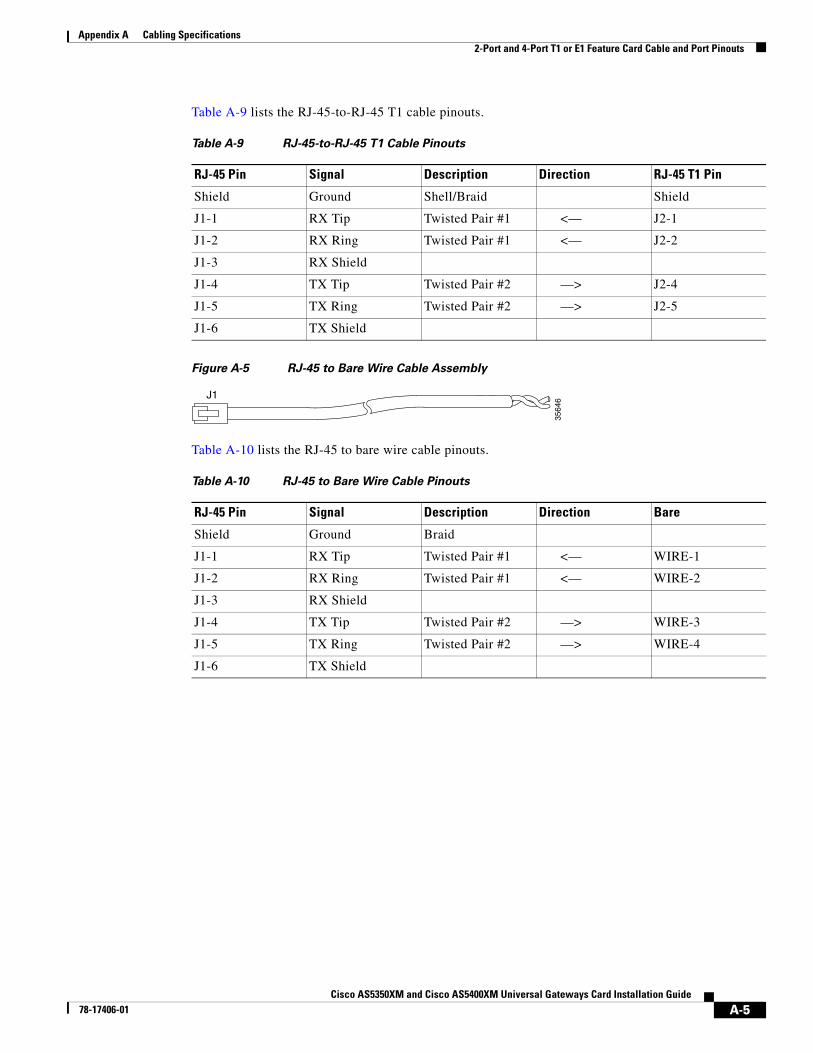
Table A-9 lists the RJ-45-to-RJ-45 T1 cable pinouts.
Figure A-5 RJ-45 to Bare Wire Cable Assembly
Table A-10 lists the RJ-45 to bare wire cable pinouts.
Table A-9 RJ-45-to-RJ-45 T1 Cable Pinouts
RJ-45 Pin Signal Description Direction RJ-45 T1 Pin
Shield Ground Shell/Braid Shield
J1-1 RX Tip Twisted Pair #1 <— J2-1
J1-2 RX Ring Twisted Pair #1 <— J2-2
J1-3 RX Shield
J1-4 TX Tip Twisted Pair #2 —> J2-4
J1-5 TX Ring Twisted Pair #2 —> J2-5
J1-6 TX Shield
3564
6J1
Table A-10 RJ-45 to Bare Wire Cable Pinouts
RJ-45 Pin Signal Description Direction Bare
Shield Ground Braid
J1-1 RX Tip Twisted Pair #1 <— WIRE-1
J1-2 RX Ring Twisted Pair #1 <— WIRE-2
J1-3 RX Shield
J1-4 TX Tip Twisted Pair #2 —> WIRE-3
J1-5 TX Ring Twisted Pair #2 —> WIRE-4
J1-6 TX Shield
A-5Cisco AS5350XM and Cisco AS5400XM Universal Gateways Card Installation Guide
78-17406-01
Appendix A Cabling Specifications8-Port T1 or E1 Feature Card Cable and Port Pinouts
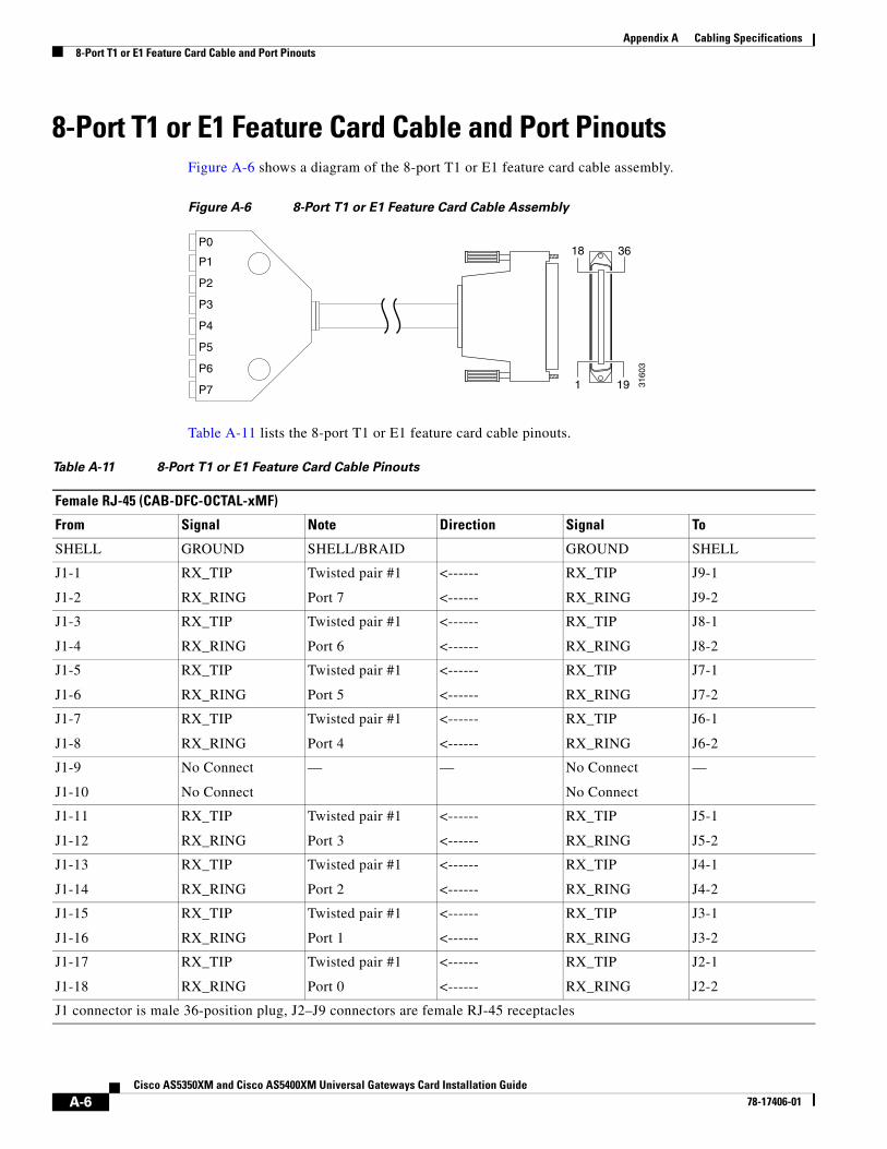
8-Port T1 or E1 Feature Card Cable and Port PinoutsFigure A-6 shows a diagram of the 8-port T1 or E1 feature card cable assembly.
Figure A-6 8-Port T1 or E1 Feature Card Cable Assembly
Table A-11 lists the 8-port T1 or E1 feature card cable pinouts.
3160
3
18
1 19
36P1
P2
P3
P4
P5
P6
P7
P0
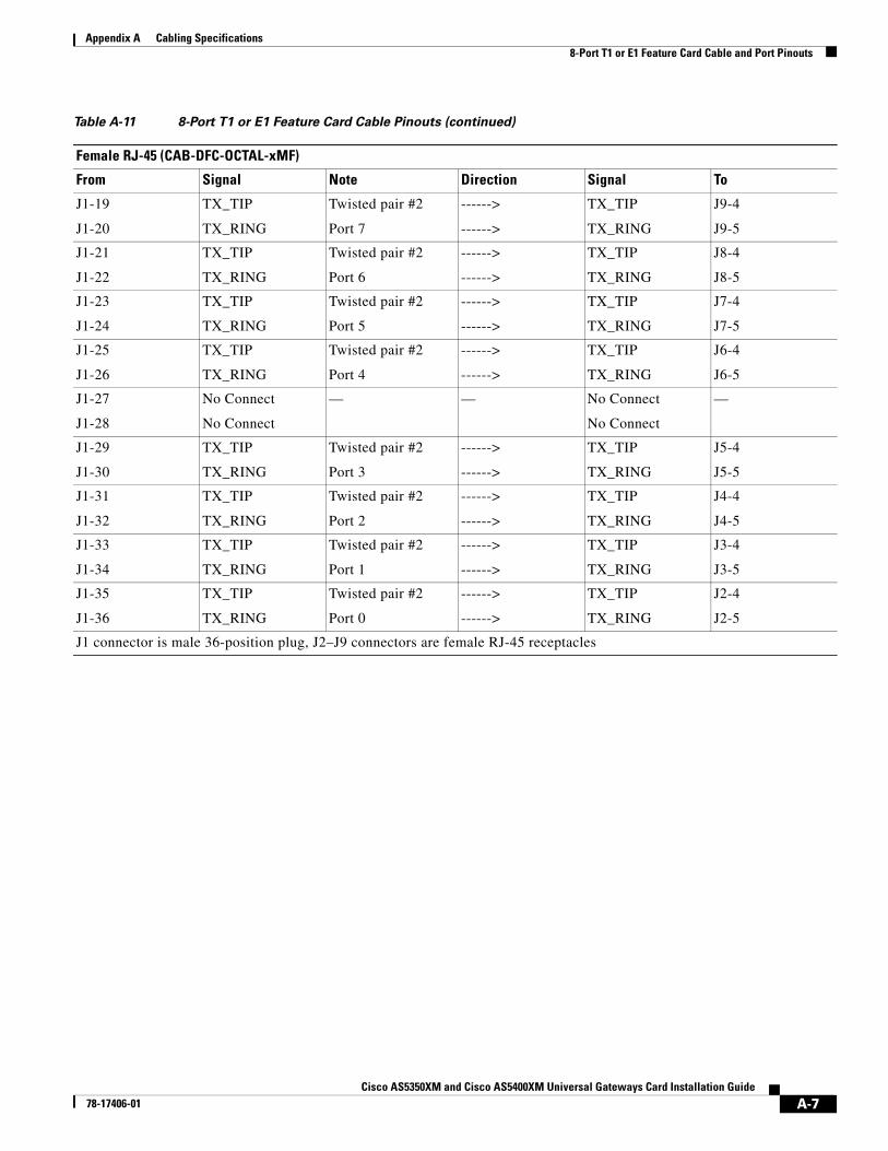
Table A-11 8-Port T1 or E1 Feature Card Cable Pinouts
Female RJ-45 (CAB-DFC-OCTAL-xMF)
From Signal Note Direction Signal To
SHELL GROUND SHELL/BRAID GROUND SHELL
J1-1
J1-2
RX_TIP
RX_RING
Twisted pair #1
Port 7
<------
<------
RX_TIP
RX_RING
J9-1
J9-2
J1-3
J1-4
RX_TIP
RX_RING
Twisted pair #1
Port 6
<------
<------
RX_TIP
RX_RING
J8-1
J8-2
J1-5
J1-6
RX_TIP
RX_RING
Twisted pair #1
Port 5
<------
<------
RX_TIP
RX_RING
J7-1
J7-2
J1-7
J1-8
RX_TIP
RX_RING
Twisted pair #1
Port 4
<------
<------
RX_TIP
RX_RING
J6-1
J6-2
J1-9
J1-10
No Connect
No Connect
— — No Connect
No Connect
—
J1-11
J1-12
RX_TIP
RX_RING
Twisted pair #1
Port 3
<------
<------
RX_TIP
RX_RING
J5-1
J5-2
J1-13
J1-14
RX_TIP
RX_RING
Twisted pair #1
Port 2
<------
<------
RX_TIP
RX_RING
J4-1
J4-2
J1-15
J1-16
RX_TIP
RX_RING
Twisted pair #1
Port 1
<------
<------
RX_TIP
RX_RING
J3-1
J3-2
J1-17
J1-18
RX_TIP
RX_RING
Twisted pair #1
Port 0
<------
<------
RX_TIP
RX_RING
J2-1
J2-2
J1 connector is male 36-position plug, J2–J9 connectors are female RJ-45 receptacles
A-6Cisco AS5350XM and Cisco AS5400XM Universal Gateways Card Installation Guide
78-17406-01
Appendix A Cabling Specifications8-Port T1 or E1 Feature Card Cable and Port Pinouts
J1-19
J1-20
TX_TIP
TX_RING
Twisted pair #2
Port 7
------>
------>
TX_TIP
TX_RING
J9-4
J9-5
J1-21
J1-22
TX_TIP
TX_RING
Twisted pair #2
Port 6
------>
------>
TX_TIP
TX_RING
J8-4
J8-5
J1-23
J1-24
TX_TIP
TX_RING
Twisted pair #2
Port 5
------>
------>
TX_TIP
TX_RING
J7-4
J7-5
J1-25
J1-26
TX_TIP
TX_RING
Twisted pair #2
Port 4
------>
------>
TX_TIP
TX_RING
J6-4
J6-5
J1-27
J1-28
No Connect
No Connect
— — No Connect
No Connect
—
J1-29
J1-30
TX_TIP
TX_RING
Twisted pair #2
Port 3
------>
------>
TX_TIP
TX_RING
J5-4
J5-5
J1-31
J1-32
TX_TIP
TX_RING
Twisted pair #2
Port 2
------>
------>
TX_TIP
TX_RING
J4-4
J4-5
J1-33
J1-34
TX_TIP
TX_RING
Twisted pair #2
Port 1
------>
------>
TX_TIP
TX_RING
J3-4
J3-5
J1-35
J1-36
TX_TIP
TX_RING
Twisted pair #2
Port 0
------>
------>
TX_TIP
TX_RING
J2-4
J2-5
Table A-11 8-Port T1 or E1 Feature Card Cable Pinouts (continued)
Female RJ-45 (CAB-DFC-OCTAL-xMF)
From Signal Note Direction Signal To
J1 connector is male 36-position plug, J2–J9 connectors are female RJ-45 receptacles
A-7Cisco AS5350XM and Cisco AS5400XM Universal Gateways Card Installation Guide
78-17406-01
Appendix A Cabling Specifications8-Port T1 or E1 Feature Card Cable and Port Pinouts
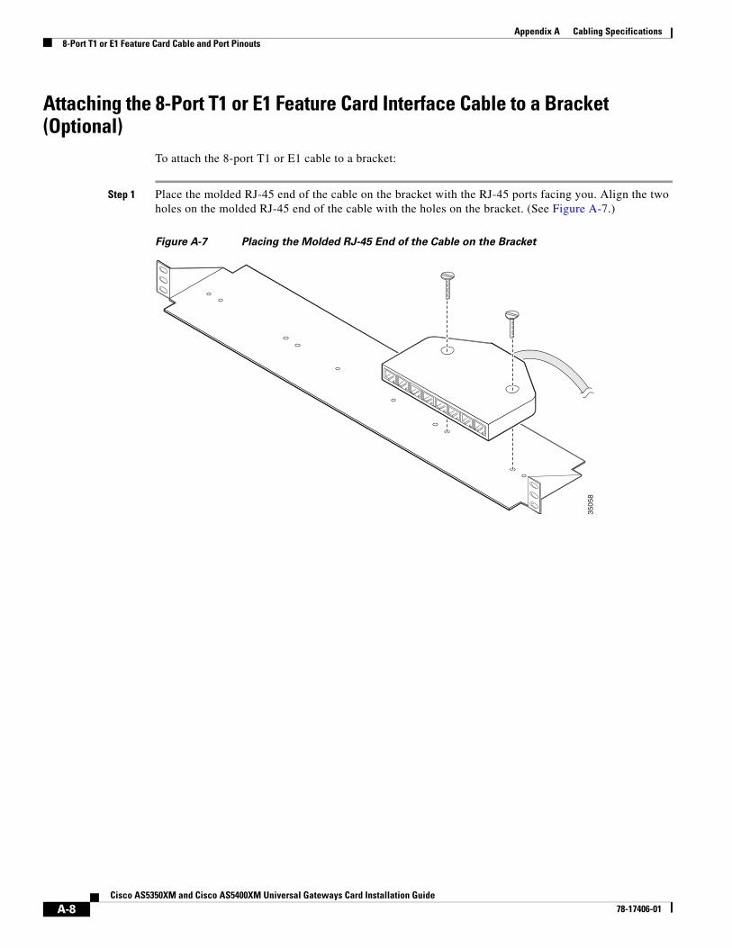
Attaching the 8-Port T1 or E1 Feature Card Interface Cable to a Bracket (Optional)
To attach the 8-port T1 or E1 cable to a bracket:
Step 1 Place the molded RJ-45 end of the cable on the bracket with the RJ-45 ports facing you. Align the two holes on the molded RJ-45 end of the cable with the holes on the bracket. (See Figure A-7.)
Figure A-7 Placing the Molded RJ-45 End of the Cable on the Bracket
3505
8
A-8Cisco AS5350XM and Cisco AS5400XM Universal Gateways Card Installation Guide
78-17406-01
Appendix A Cabling Specifications8-Port T1 or E1 Feature Card Cable and Port Pinouts
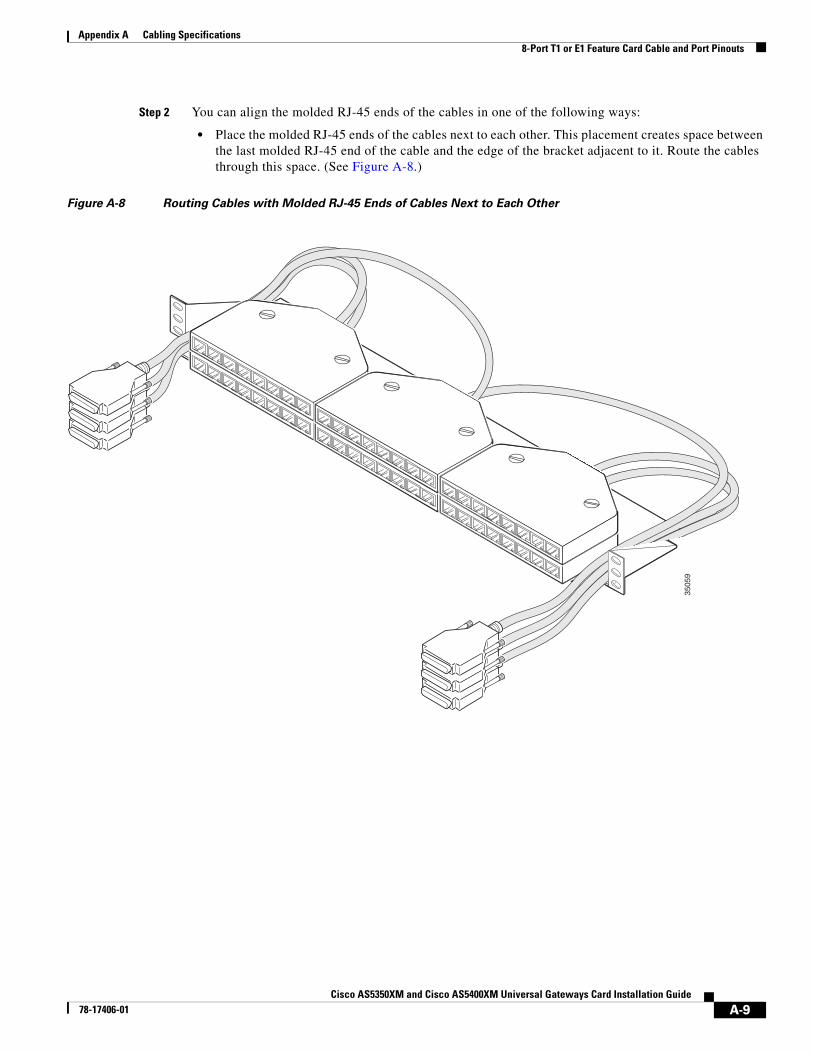
Step 2 You can align the molded RJ-45 ends of the cables in one of the following ways:
• Place the molded RJ-45 ends of the cables next to each other. This placement creates space between the last molded RJ-45 end of the cable and the edge of the bracket adjacent to it. Route the cables through this space. (See Figure A-8.)
Figure A-8 Routing Cables with Molded RJ-45 Ends of Cables Next to Each Other
3505
9
A-9Cisco AS5350XM and Cisco AS5400XM Universal Gateways Card Installation Guide
78-17406-01
Appendix A Cabling Specifications8-Port T1 or E1 Feature Card Cable and Port Pinouts
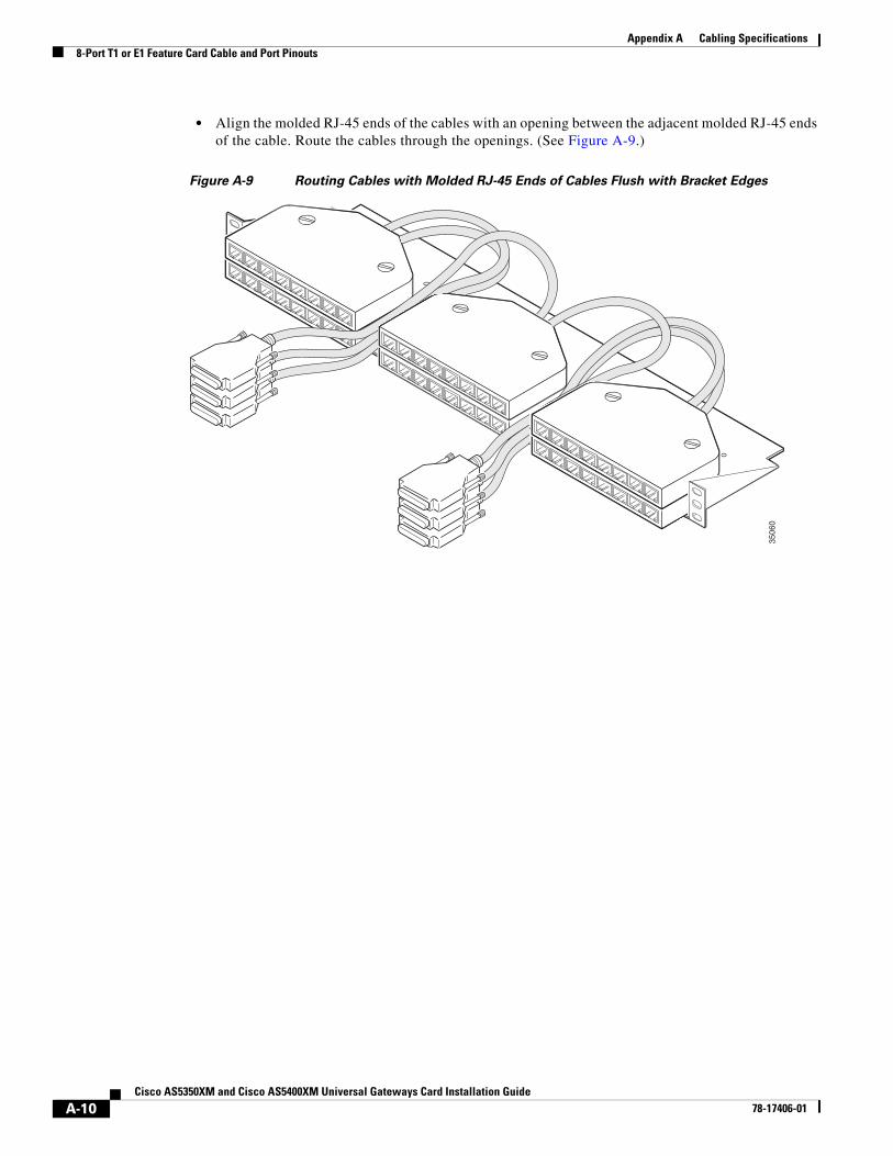
• Align the molded RJ-45 ends of the cables with an opening between the adjacent molded RJ-45 ends of the cable. Route the cables through the openings. (See Figure A-9.)
Figure A-9 Routing Cables with Molded RJ-45 Ends of Cables Flush with Bracket Edges
3506
0
A-10Cisco AS5350XM and Cisco AS5400XM Universal Gateways Card Installation Guide
78-17406-01
Appendix A Cabling Specifications8-Port T1 or E1 Feature Card Cable and Port Pinouts
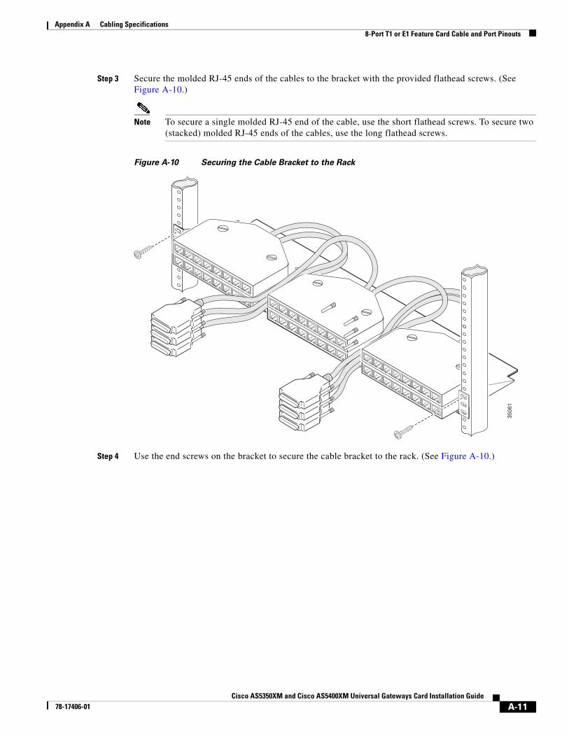
Step 3 Secure the molded RJ-45 ends of the cables to the bracket with the provided flathead screws. (See Figure A-10.)
Note To secure a single molded RJ-45 end of the cable, use the short flathead screws. To secure two (stacked) molded RJ-45 ends of the cables, use the long flathead screws.
Figure A-10 Securing the Cable Bracket to the Rack
Step 4 Use the end screws on the bracket to secure the cable bracket to the rack. (See Figure A-10.)
3506
1
A-11Cisco AS5350XM and Cisco AS5400XM Universal Gateways Card Installation Guide
78-17406-01
Appendix A Cabling SpecificationsCT3 Feature Card Cable and Port Pinouts
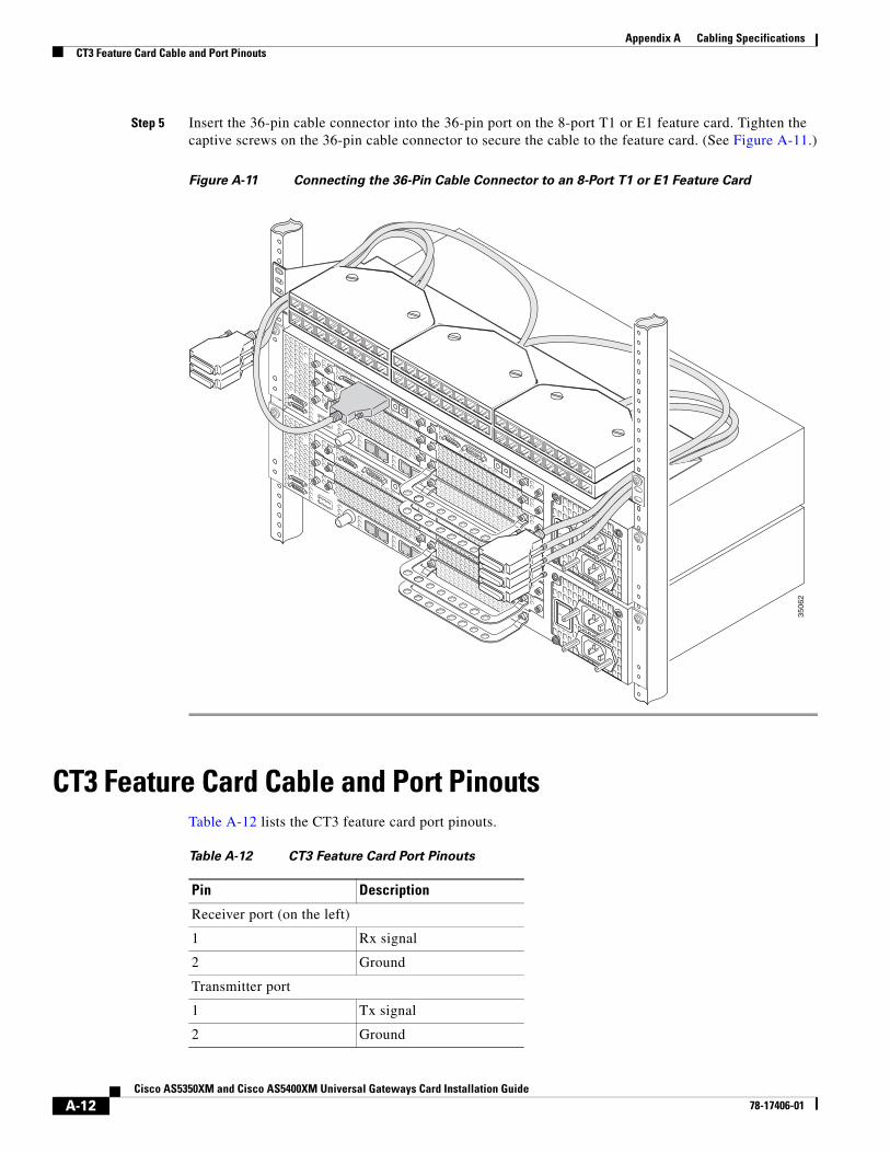
Step 5 Insert the 36-pin cable connector into the 36-pin port on the 8-port T1 or E1 feature card. Tighten the captive screws on the 36-pin cable connector to secure the cable to the feature card. (See Figure A-11.)
Figure A-11 Connecting the 36-Pin Cable Connector to an 8-Port T1 or E1 Feature Card
CT3 Feature Card Cable and Port PinoutsTable A-12 lists the CT3 feature card port pinouts.
3506
2
Table A-12 CT3 Feature Card Port Pinouts
Pin Description
Receiver port (on the left)
1 Rx signal
2 Ground
Transmitter port
1 Tx signal
2 Ground
A-12Cisco AS5350XM and Cisco AS5400XM Universal Gateways Card Installation Guide
78-17406-01
Appendix A Cabling SpecificationsBantam Jack Port Pinouts
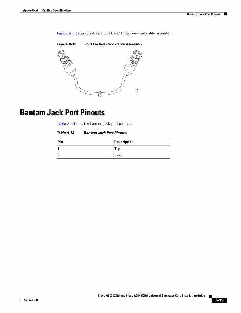
Figure A-12 shows a diagram of the CT3 feature card cable assembly.
Figure A-12 CT3 Feature Card Cable Assembly
Bantam Jack Port PinoutsTable A-13 lists the bantam jack port pinouts.
1295
1
Table A-13 Bantam Jack Port Pinouts
Pin Description
1 Tip
2 Ring
A-13Cisco AS5350XM and Cisco AS5400XM Universal Gateways Card Installation Guide
78-17406-01

Appendix A Cabling SpecificationsBantam Jack Port Pinouts
A-14Cisco AS5350XM and Cisco AS5400XM Universal Gateways Card Installation Guide
78-17406-01