
Cabling Diagrams for Schematic Circuit Drawings...
20
BELL SYSTEM PRACTICES Plant Series CABLING DIAGRAMS FOR SCHEMATIC CIRCUIT DRAWINGS GENERAL EQUIPMENT REQUIREMENTS 1. 2. v 1. CONTENTS PAGE GENERAL . . . . . . . . . . . DETAILS OF CABLING, TERMINAL ASSIGNMENT, AND CROSS-CONNECTING INFORMATION . . . . . . . . . A. B. c. D. E. F. G. H. I. J. K. L. Numbering of Figures . . . . . . Conventions — General . . . . . Terminal Strip Conventions . . . . Orientation Symbols . . . . . . Terminal Assignment . . . . . . General . . . . . . . . . . Specific . . . . . . . . . . Lead and Terminal Designations . . Lead Terminations . . . . . . . Switchboard Cabling and Wire . . . Wires Functionally Unassigned . . . Cross Connections . . . . . . . Straps . . . . . . . . . . . Optional Wiring . . . . . . . . GENERAL 1 3 3 4 5 7 10 10 11 15 16 17 18 i9 19 20 1.01 This section describes the assignment of terminals for cabling, lead multiplying, and cross-connecting information for circuit sche- matic drawings. 1.02 This section is reissued to incorporate pre- vious addendum changes. 1.03 This section for the most part is informa- tional in character reflecting current prac- tices, since the assignment of terminals, lead multiplying, and cross-connecting information are general 1y design matters. Where not positively directed herein, or where the cabling informa- tion is not covered in the design information, this section may be considered as a guide. It is the responsibility of the Bell Telephone Laboratories engineer to cover the assignment of terminals, lead multiplying, and cross-connecting informa- tion on the circuit schematic drawings or speci- fications. SECTION 800-610-153 Issue 7, October 1968 AT&TCo Standard 1.04 Except for distributing frames, when cross connections are subject to periodic changes, the application, location, and assign- ment of terminals and color, gauge and type of wire used, which have sometimes been covered in Bell System Practices, have been included on more recent schematic drawings. Whenever ex- isting schematic drawings are reissued, consider- ation should be given to the inclusion of this type of information. 1.05 Cabling, terminal assignment, lead mul- tiplying, and some cross-connecting infor- mation is included on circuit schematic drawings in separate figures to show the method of wiring between units of equipment or pieces of appa- ratus. These figures, previously referred to as cross-connection figures, are now referred to as Cabling Diagrams (CADS) to distinguish them from the cross-connection in fcmmation referred to in 1.04 above. 1.06 On CAD figures, wiring which is internal to the equipment is in general shown on the right side of the terminal convention and drawn to the right to indicate a shop connection. This is referred to herein as the shop side of the terminal strip. Wiring which is external to the equipment is in general shown on the left side of the terminal convention and drawn to the left to indicate an installer connection. This is referred to herein as the installer side of the terminal strip. The proper location of the lead on the terminal convention should be followed even if for some reason the shop must connect to the installer side or the installer must con- nect to the shop side of the terminal strip. (See Fig. 1.) It should be recognized that in some cases, as a matter of economy, the shop may connect what is normally called installer wiring. -1.07 cuits. (a) (b) CADS cover the assignment of terminals and the method of tying in connecting cir- They show: The assignment of all terminals including terminals on distributing frames. All wiring connected to each terminal. cc American Te]enhone and TelegraDh Comt)anv. 1968 ‘Printed in U.S~A.‘ “ - Page 1
Transcript of Cabling Diagrams for Schematic Circuit Drawings...

BELL SYSTEM PRACTICESPlant Series
CABLING DIAGRAMS
FOR SCHEMATIC CIRCUIT DRAWINGS
GENERAL EQUIPMENT REQUIREMENTS
1.
2.
v
1.
CONTENTS PAGE
GENERAL . . . . . . . . . . .
DETAILS OF CABLING, TERMINAL
ASSIGNMENT, AND CROSS-CONNECTING
INFORMATION . . . . . . . . .
A.
B.
c.
D.
E.
F.
G.
H.
I.
J.
K.
L.
Numbering of Figures . . . . . .
Conventions — General . . . . .
Terminal Strip Conventions . . . .
Orientation Symbols . . . . . .
Terminal Assignment . . . . . .
General . . . . . . . . . .
Specific . . . . . . . . . .
Lead and Terminal Designations . .
Lead Terminations . . . . . . .
Switchboard Cabling and Wire . . .
Wires Functionally Unassigned . . .
Cross Connections . . . . . . .
Straps . . . . . . . . . . .
Optional Wiring . . . . . . . .
GENERAL
1
3
3
4
5
7
10
10
11
15
16
17
18
i9
19
20
1.01 This section describes the assignment ofterminals for cabling, lead multiplying, and
cross-connecting information for circuit sche-matic drawings.
1.02 This section is reissued to incorporate pre-vious addendum changes.
1.03 This section for the most part is informa-tional in character reflecting current prac-
tices, since the assignment of terminals, leadmultiplying, and cross-connecting information aregeneral 1y design matters. Where not positivelydirected herein, or where the cabling informa-tion is not covered in the design information, thissection may be considered as a guide. It is theresponsibility of the Bell Telephone Laboratoriesengineer to cover the assignment of terminals,lead multiplying, and cross-connecting informa-tion on the circuit schematic drawings or speci-fications.
SECTION 800-610-153
Issue 7, October 1968
AT&TCo Standard
1.04 Except for distributing frames, when crossconnections are subject to periodic
changes, the application, location, and assign-ment of terminals and color, gauge and type ofwire used, which have sometimes been coveredin Bell System Practices, have been included onmore recent schematic drawings. Whenever ex-isting schematic drawings are reissued, consider-ation should be given to the inclusion of thistype of information.
1.05 Cabling, terminal assignment, lead mul-tiplying, and some cross-connecting infor-
mation is included on circuit schematic drawingsin separate figures to show the method of wiringbetween units of equipment or pieces of appa-ratus. These figures, previously referred to ascross-connection figures, are now referred to asCabling Diagrams (CADS) to distinguish themfrom the cross-connection in fcmmation referredto in 1.04 above.
1.06 On CAD figures, wiring which is internalto the equipment is in general shown on
the right side of the terminal convention anddrawn to the right to indicate a shop connection.This is referred to herein as the shop side of theterminal strip. Wiring which is external to theequipment is in general shown on the left sideof the terminal convention and drawn to theleft to indicate an installer connection. This isreferred to herein as the installer side of theterminal strip. The proper location of the leadon the terminal convention should be followedeven if for some reason the shop must connectto the installer side or the installer must con-nect to the shop side of the terminal strip. (SeeFig. 1.) It should be recognized that in somecases, as a matter of economy, the shop mayconnect what is normally called installer wiring.
-1.07
cuits.
(a)
(b)
CADS cover the assignment of terminalsand the method of tying in connecting cir-
They show:
The assignment of all terminals includingterminals on distributing frames.
All wiring connected to each terminal.
cc American Te]enhone and TelegraDh Comt)anv. 1968
‘Printed in U.S~A.‘ “ - Page 1

f[I SECTION 800-610-153I
CONN TO INSTALLERSSIOE BY INSTALLER
CONN TO SHOP SIDEBY INSTALLER
STRAP ON INSTALLERSSIDE BY INSTALLER
STRAP ON SHOPSIDE BY INSTALLER
Q
o~ CONN TO SHOP
SIOE BY SHOP
o
L
o
P CONN TO INSTALLERSSIDE BY SHOP
-’i
STRAP ON SHOPSIDE BY SHOP
o
0
%--STRAP ON INSTALLERS—
SIDE BY SHOP
TS ON UNIT
Fig.1 -Method of Showing Shop and installer Wiring on Terminal Strips
(c) Switchboard cable from other units, bays,or frames which is carried directly to ap-
paratus (not through terminals), for example,switchboard cable terminating directly onmulticontact relays.
(d) The wiring method for each lead wherethe method is not obvious.
Examples: (1) Switchboard cable, (2)switchboard cable or bulk wire via cableracks, (3) “loose wire” (within bay orframe), (4) cross connections, (5) straps,(6) local cable, (7) supplementary localcable.
(e) The point of connection at a terminalwhere terminal includes more than one
notch or where a specific location is requiredfor a solderless wrapped connection on a ter-minal.
Examples: (1) “Connect in inner notch.”(2) “SS” surface strapping. (3) “SH” shankconnection.
(f) The conditions controlling the running,connection, or removal of any variable
wiring which is not identified with an optiondesignation.
1.08 Enough information is shown to insureproper identification of apparatus, ter-
minal assignments, cable, and wire. In general,no apparatus other than terminal strips or ter-minals shall be shown as part of the CAD. Leadsto other circuits on the same frame via localcable that are bypassing terminal strips need notbe shown in the CAD unless required. Pairingof leads shall be shown in the CAD but only onthe installer side of the drawing. The explana-tion of the various symbols used to describe theposition of terminal strips and type of wiring iscovered in Section 005-150-101.
1.09 In general, distributing frame cabling dia-grams shall be shown as CAD figures
separate from those for the relay units, switch-boards, etc.
(a) On trunk and line circuits cross connectedto tol 1 switchboards, and on station system
circuits the distributing frame informationshown on the schematic drawing may be con-sidered typical. On wiring diagrams, the ter-minals may be assigned and designated asrequired, within the framework of the re-quirements stated herein.
Page 2

1SS 7, SECTION 800-610-153
1.10 Where standard arrangements permiteither cross connections or direct cabling,
both shall be shown. (See Fig. 2.)
1.11 CAD figures shall not include orderinginformation normally called for else-
where in the drawing and in no case should theycover outside plant information.
1.12 In connection with certain toll equipment,such as program transmission, carrier
telephone, PBX, and certain electronic switchingsystems, a separate drawing is prt’pared, calledan application schematic, on which a completeset of cabling diagrams is shown, including cross-connection, terminal strip, and cabling informa-tion for all of the individual circuits shownthereon. Where this is done, no cabling informa-tion appears on the individual circuits and anequipment note shall be shown referring to theapplication schematic for this information. Insome cases where the individual circuits do notcover complete terminal strip information, itmay be desirable to do so by means of cablingdiagrams on the application schematic.
1.13 In step-by-step systems, separate draw-ings are sometimes prepared to show line
cabling and cross-connecting information forv the various approved distributing frame arrange-
ments. The line circuit schematics refer to thesedrawings by numbers in notes on the circuitschematic drawings.
1.14
tiona
On some of the larger circuits (such asmarkers) where a large number of func-schematics are involved, separate CAD
CROSSCONNTO CX
CKT
TO CXCKT
figures are provided for each App Fig. (Appa-ratus Figure) showing only the local cable, relaydesignation, relay contact number, and leaddesignations. These CAD figures are associatedwith other CAD figures which show the abovementioned local cable, terminal strip, and switch-board cabling to other frames. With this arrange-ment, the CAD figures associatcci with the AppFig. are numbered from 1 to 99 (the CAD figurenumber generally agrees with the App Fig. num-ber). The CAD figures associated with theswitchboard cabling are numbered from 100 up.
1.15 In some PBX systems where a largeamount of the cabling is connected to
connectors, a separate schematic drawing hasbeen prepared to cover the complete cablinginformation for one system. One such methodused on a PBX system (757A), shows the CADfigures in tabular form, see SD-66735-01. An-other approach, part tabular, part pictorial, hasbeen on the 2A Automatic Call DistributingSystem, see SD-67008-01. The above principlehas also been applied to the No. 1 AMA systemexcept that the tabular form CADS are not sepa-rate drawings, see SD-40034-01.
2. DETAILS OF CABLING, TERMINAL ASSIGNMENT,
AND CROSS-CONNECTING INFORMATION
A. Numbering of Figures
2.01 On all new drawings the CAD figures shallbe numbered consecutively starting with
one and have a prefix CAD; that is, CAD 1,
:E:‘ :!’*’,T!
~ S2 OR 21
,~’ (A) REP s20RCOIL CKT 2
T 9
R PH ‘“”tp(A)REp ~H12 COIL
HIOF‘B
n
i
II I
OMIT FORNON- QUADDED
~P LINES‘T
R S1
T ~P
R s2 i I
T f-P II ’11k~PI+
1 I Iw
Fig. 2- Method of Showing Cross Connections or Direct Cabling
Page 3
SECTION 800-610-153
CAD 2, etc. On existing drawings, the figuresshall be numbered as follows.
(a) on reissued drawings on which there areno CAD figures and CAD figures are to
be added, use CAD 1, CAD 2, etc, for the addedfigures.
(b) On reissued drawings on which there arecabling diagram figures numbered Fig. 51,
Fig. 52, etc, and a cabling diagram figure is tobe added, use the same numbering system asshown on the drawing for the added figure;that is, continue with Fig. 53.
(c) On reissued drawings on which the CADfigures are numbered using a suffix letter
K, L, l!, etc; that is, 4K, and a cabling dia-gram figure is to be added, use CAD 1, etc,for the added figure.
(1) The reason for not continuing with theuse of the schematic figure number with
an additional suffix letter is because of themany complications encountered with theuse of this system.
(d) On reissued drawings using both the suffixletter, 4K, etc, and Fig. 51, Fig. 52, etc,
and a cabling diagram is to be added, continuewith the numbering system using Fig. 53 forthe added figure.
(e) On reissued drawings that are con~’ertedfrom the attached contact schematic type
to detached contact schematic type, the cablingdiagrams shall be numbered CAD 1, CAD 2,etc. Consideration should be given to a con-version table for office records.
2.02 The CAD figure, except on detached-con-tact schematics, shall carry a reference to
the associated circuit schematic figure number ornumbers. These cross-references shall be shownin the following manner, using an adequatescriptive figure title where necessary.
CAD 1 CAD 2
(FOR FIG. 1 & 21 (FOR FIG. 3)
TOLL SWBD 3C TOLL SWBD 3CF
CAD 3 CAD 4
(FOR FIG. 1 & 2) (FOR FIG. 1 & 2)
ALM REL AIS PIL 1P
de-
(a) On some of the larger circuits (such assenders and markers) where several
sheets are involved, a cross-reference tablebetween the circuit schematic figures andassociated cabling diagram figures may beprovided, or the corresponding cabling dia-gram figure number may be shown under thetitle of the schematic figure number in thefollowing manner.
FIG. 6COIN
CAD 1
2.03 On detached-contact schematics, the asso-ciated apparatus figure number or num-
bers shall be shown under the CAD figure in thefollowing manner.
CAD 1
(FOR FIG. 1, 2, 4)
B. Conventions — General
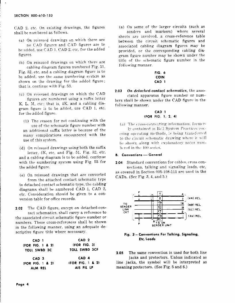
2.04 Standard conventions for cables, cross con-nections, talking and signaling leads, etc,
as covered in Section 005-108-111 are used in theCADS. (See Fig. 3,4, and 5.)
P n
TOSENOER
LINKCKT
rSENOEi? UNIT
(KR) REL
(MB) REL
(SC) REL
(AV) REL
Fig. 3- Conventions For Talking, Signaling,
Etc, Leads
2.05 The same convention is used for both linejacks and protectors. Unless indicated as
line jacks, the symbol will be interpreted asmeaning protectors. (See Fig. 5 and 6.)
Page 4

I
1SS 7, SECTION 800-610-153
t
C::2
TO OTHERTRuNKS IN SAMETRAFFIC GROUP
&MKU:~
SWBD
(L)lNf3t?
10
I SL II 1-7
6 (Mi REL
‘L 18TO (L) LAMPS n *B (L U)REL1
TO ALL TRUNKS K n Q3M (S I)REL
BUSY REG CKT 101 (M)REL,
[ ‘:~;T 14 3
TOSEL OR R 15
1
4 (M)REL
SEL :ORN~AB$~KSs 16
4 (SI)REL
x 17(A)REs
Ss g
[
46VSIG n 19
TO o
FuSE PNL G 20B (M)REL
LW WHEN ON YTS
SAME FRAME OR BAYON UNIT
Fig. 4-Terminations Shown at Ends of Leads
(224-type terminal strip shown)
Pv H
MDF
Fig. 5- Protectors Shown on Vertical Side
of the MDF
2.06 When the shield of shielded wiring (withor without a ground tracer) is connected
to a terminal, it is shown by a solid lead fromthe shield convention to the terminal. (SeeFig. 7).
n
TO DIAL PULSECONVERTER CKT
ToCAD2
r
TI i ..,A I: (FT)
RI :, z(FR)
FS 3
I*’ ~
(FT)RT ,/ u 4
(RT)RR :’ !3
(RR)RS 6
,, ,,(RT). 16❑ ‘GE (Rl).
Ts (A)
ON UNIT
CAP
CAP.
RES
CAP.
CAP.
RES
RE S
Fig. 7- Method of Showing Shielding
(203-type terminal strip shown)
C. Terminal Strip Conventions
2.07 The terminal strip convention shall notbe shown around the terminals, except
distributing frame terminal strips (see 2.08)or where it is necessary to show the location ofterminals with respect to each other (see Fig. 3).In general, all the terminals (used and unused)are shown in \’ertical rows and are numberedfrom top to bottom or bottom to top. (See Fig. 8and 9.) Terminals may be shown out of orderwhere it improves the layout of the diagram orwhere a special grouping is desired.
2.08 On distributing frame terminal strips theterminal strip convention shall be shown
around the entire row of terminals which are
JACKS ~f---MDF H13DF
ORHTDF
Fig. 6- Distributing Frame Information Shown as Separate Figure,
Also Method of Showing Line Jacks
Page 5

SECTION 800-610-153
TOCAD2
PT ‘~ I
R II 1 3 2‘1
P
(SV)REL
TI A i 5
RI(T) RES
(R) RES
KORS 9 6T
LORLI))
(K) 1STRCL CKT
.- .--;---- ,.:’
--- 1---~=::;::--Ii 1____CKT-----13
7 )
4TH---- —- CKT
:/
---—
------.-----
5THCKT
6THcUT
7THCKT
8THCKT
2.3
~
2:6
2.7
:~T4:; S0 d!n 20
FuSE BAY
[,: ‘%
SBWY $0
TO 24VBAT AT ~5’ 1(K)REL
FuSE BAY 2 ST
TS (A)I ON UNIT
A---A ---
$ 19TH---- -- CKT
---- --
1
IOTH
---- --
--- x---j ::
-- +--/ CK’
TO
[
KORS
CAD2 LORLI‘-‘] !2TH-- -) CKT
~
Fig. 8- Terminals
(224-type
6
2;
TS (S)ON UNIT
Numbered From Top to Bottom
terminal strip shown)
32 TORR4 GRD VIA
31 (SP) RELo
300
TO 4!3V SIG n 29(C) RES
FUSE PNL28
TO SOR LINKa CONN CKT
TO CAO 5
TO INC LINKANO CONN CKT
(TOLL coMpL,INTERTOU ORCOMB. TRAIN)OR TO CAD 2
OR CA03
TO CAO 4
TO CAO 6
u
o26
“151E&)
‘ (CO) REL25 I
(SP)24 z REL
I co 23 2M”(CO) REL
=%-PJ
%ikSMC 17Is o
R P 16
T o
‘GEIs 3.
“SMI 14
SMC 13
&)
(co)REL
IT I 1 7 6
P
I“ <1
(5P)IR 6 3B REL
IT 5 6B
.
[: :’ ‘ : :’
EORL 46 (CO) REL
s 3 (TM13)
P 2JACK
R II
I
1
(5P)T 12 REL
(RL ‘P T-SON UNIT
Fig, 9- Terminals Numbered From Bottom to Top
(227-type terminal strip shown)
Page 6

1SS 7, SECTION 800-610-153
I
perpendicular to the fanning strip, except asotherwise indicated below. (See Fig. 10.)
(a) Where miscellaneous terminals on a dis-tributing frame terminal strip are shown
and they do not include the entire row, theterminal strip convention may be broken offto include only the terminals involved. In thiscase, the convention may be broken off atboth ends, and if orientation of the terminalsis necessary, the one nearer the base shouldbe marked “Terminal Toward Base. ”
(b) In general, cabling diagram figures shallnot depict terminal strips and wiring
shown in some other figure or drawing. Whereunusual circumstances warrant repeating thisinformation, the terminal strip and wiringshall be shown in light dash lines with a noteindicating the figure or drawing in which theyappear. The terminal strip convention may bebroken off and only the terminals involvedshown.
2.09 The convention for the 66-type connectingblock is shown in Fig. 11 and 12. All ter-
minal clips are shown when this block is shownin the CAD section of a drawing. When the con-
* netting block used has two or more separate
CROSS CONNTO TEL,KEY
a LAMP CKT
clip multiples in one horizontal row, the repre-sentation of the terminals shall be staggered asshown in Fig. 12 or the lower half of Fig. 11.
2.10 When the terminal strip is equipped withU-shaped or similar type terminals, such
as the 284-, 285- or 203-type terminal strip, itis only necessary to show one terminal symbolfor each terminal on the CAD figure. (See Fig.17. ) Two terminal symbols connected with asolid line may be shown when necessary.
D. Orientation Symbols
2.1? When the terminal strip convention showsa row of terminals which are perpendicu-
lar to the fanning strip, the terminal nearestto the base (fanning strip) is designated withthe symbol B. When two fanning strips are pro-vided, the terminals nearest the lower (for hori-zontal mounting) or right (for vertical mount-ing) fanning strip are designated with the sym-bol B. Where shown in the same figure, adjacentrows of terminals which are perpendicular tothe fanning strip are indicated by joining themwith a line designated E. The top or left row ofterminals on the terminalwith the symbol K. (See Fig.
4wp K
,=--4A.lz!.
( +----
HFIRST - - - -APPEARANCE _ _ _ _
2W OR 4W
1’ +-— --
‘Ii=T T2
R R2
K—
L L OR L(—
B, ‘lN:%%~ATEII
:&
T APPEARANCES
R
—
k---:-;~HID F, VIDF,
HMDF, OR HCOF
OR vCDF
Fig. 10- Distributing Frame Terminal Strips
strip is designatedlo.)
TO CAD I
Page 7

SECTION 800-610-153
TOALM CKT
A
B
IIIIII!
IY
z
CROSS CONNAS REQO
—
lzs3EiAo3TO CAO 2
I Br I
B II [ B
2 I I
I I
I I I I
II
I I ;II Y ;I
IY
II
II
II Y
\IY
I
AN—
-+
II
I
II
;
TO CAD I
00
TCONTACTS OF(AO)REL
27—
00’
[--J-3——23
74 I——— —.
Fig. 11 -Method of Showing
shown]
n (AO)ON FR
Clip-Type
CONTACTS OF(RO) REL
(66 B5-37 Connecting Block
Page 8

t
1SS 7, SECTION 800-610-153
P
fT n + I“1
IIII
RCVR (16) IND
IIiI
(16)
PB UN ii
Fig. 12- Terminal Assignment for Clip-Type
Terminals (66 E1-32 Connecting Block
shown)
2.12 On 216- and similar-type terminal strips,where there are two points of connection
on the same terminal, leads which are intendedto be connected to the lower terminal on thetc’rminal strip shall be indicated with an arrowand notf “Connect To Lower Terminal. ” (SeeFig. 13. )
front of the terminal strip and is mounted withthe cross-connecting field at the front of theframe. Strapping terminals are provided on therear of the two ends of each segment. The right-hand terminal looking at the rear of the terminalstrip shall be designated K4. (See Fig. 14. )
TS (CVF)
I/ KCV (37)
(
KC V(I)
?+-~
I \,;--‘;1:4K4
TO IICAD 5 II CROSS CONN TO
“CR” TERMINALSKCM (36)
KCM (I)
-?+-
2.13 On 236- and similar-type terminal strips(used on marker test and similar type
frames in dial systems), the side containing thecross-connecting field is looked upon as the
“ii K4,1 i, CROSS CONN TO
“CR’’TERM(NALS
Fig. 14- Use of K4 to Indicate Right-Hand Terminal
Lug of a Group of Terminals Looking at
Rear of 236- or Similar-Type Terminal Strip
\—
OTHE::AD 59
Fig. 13- Method of Showing Connection to
216-Type Terminal Strip
2.14 Except as stated herein, generally all ter-minals on the same terminal strip shall
be shown in one vertical row. A notation shall beshown below each vertical group or row of ter-minals in a figure to identify the terminal stripand show its l&ation. (See Fig. 15. )
130140150160
TS ONuNIT
4
z
6
ATS (8)AT TOPOF FR
B’
y=] J-lFB“ IOFB OR
VIDF
Fig. 15- Method of Identifying Terminal Strips
Page 9
SECTION 800-610-153
2.15 Distributing Frames
(a) On distributing frames other than theelectronic type, the terminals on the hori-
zontal side of the frame shall be shown in a .vertical row and those on the vertical side shallappear in another vertical row. Each side ofthe distributing frame is indicated by placingthe designation H or V below the bottom rowof terminals on each side. The frame designa-tion as }IDF, IDF, etc, is located centrally be-low the two rows of terminals. (See Fig. 15. )When only one side of the distributing frameis shown, the entire designation is placed belowthe bottom row of terminals on the frame. (SeeFig. 10. )
(1) If the distributing frame CAD figurecovers fr:~mes of different construction,
such as :1 (’DF and a single-sided distrib-uting frame (having no horizontal terminalstrips), the complete frame designationsshould be placed below each vertical row’ ofterminals.
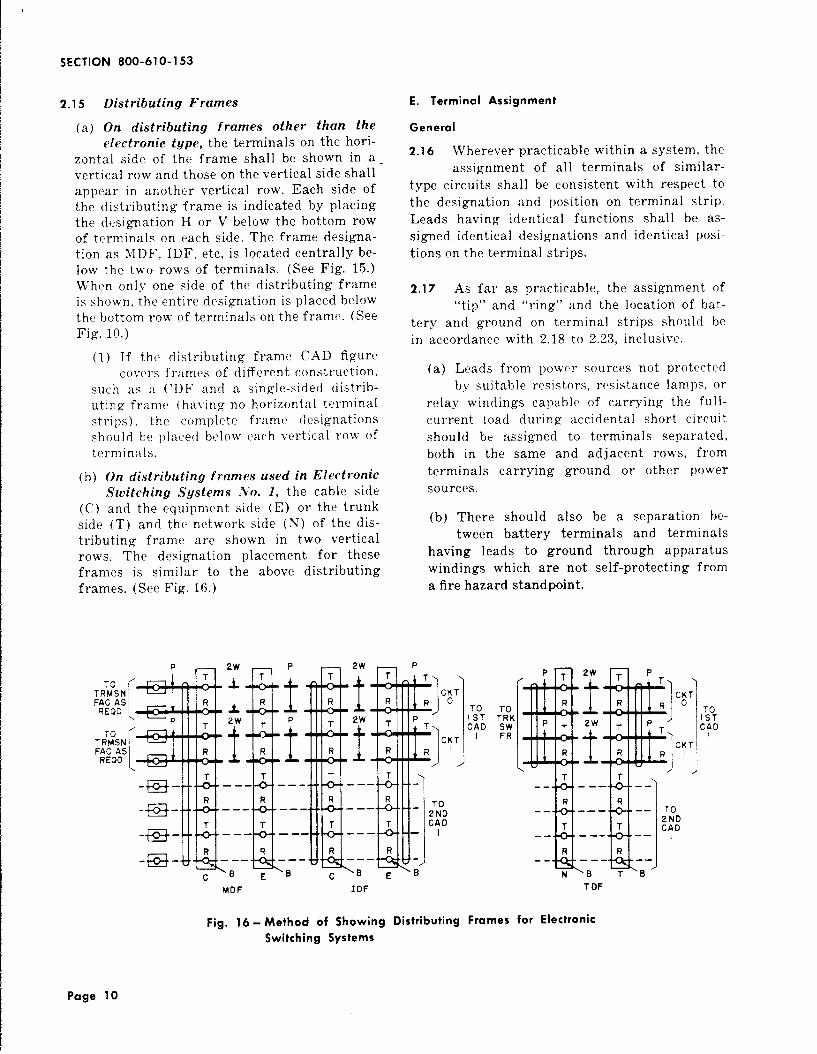
(b) On distributing frames used in ElectronicSwitching Systems ,%’o. I, the cable side
(C) and the equipment side (E) or the trunkside (T) and the network side (N) of the dis-tributing frame are shown in two verticalrows. The designation placement for theseframes is similar to the above distributingframes. (See Fig. 16. )
E. Terminal Assignment
General
2.16 Wherever practicable within a system, theassignment of all terminals of similar-
type circuits shall be consistent with respect tothe designation and position on terminal strip.Leads having identical functions shall be as-signed identical desiewations and identical posi-tions on the terminal strips.
2.17 As far as practicable, the assignment of“tip” and “ring” and the location of bat-
tery and ground on terminal strips should bein accordance with 2.18 to 2.23, inclusive.
TRTMoSN
[
I
KTFAC AS oREOD
T RT~SN
[
KTFAC ASREOO
(a) Leads from power sources not protectedby suitable resistors, resistance lamps, or
relay windings capable of carrying the full-current ioad during accidental short circuitshould be assigned to terminals separated,both in the same and adjacent rows, fromterminals carrying ground or other powersources.
(b) There should also be a separation be-tween battery terminals and terminals
having leads to ground through apparatuswindings which are not self-protecting froma fire hazard standpoint.
MDF IDF
TOI STCAD
‘ ._p.&+g_., ‘ ‘
IiMlR R
-- —— ---2T:D
T T CAD-- ----—
R R-- -----
NB TB
T DF
Fig. 16- Method of Showing Distributing Frames for Electronic
Switching Systems
Page 10

I
1SS 7, SECTION 800-610-153
Specific
2.18 On ,150-, 178-, 268-, 183-, and similar-typeterminal strips, in assigning terminals in
a row of terminals which are perpendicular tothe fanning strip, the “tip” lead should be shownconnected ti the terminal farthest from the fan-ning strip; “ring” to the next farthest terminalfrom the fanning strip; “sleeve” next ; and so onin toward the fanning strip.
2.19 On 203-, 259-, and 284-tgpe terminal strips,+-“tip” and “ring” should be shown con-
nected to the lowest numbered terminals on theterminal strip. (See Fig. 17. )
(a) Connect ground to the highest numberedterminal and allow at least two interven-
ing terminals between battery and ground.
(b) At least two intervening terminals shouldseparate two battery terminals of differ-
ent potentials, or ringing battery and ground.Separation also should be provided, when nec-essary, to avoid inductive interference, theamount of separation to depend on the re-quirements of the particular job. (See Fig. 17. )
‘“::%”[++y:w’.;:TO FUSE PNL
TSONRR UNIT
Fig. 17- The 203-Type Terminal Strip
2.20 The 224-Type Terminal Strips
224A and 224F
(a) In general, ‘(tip” and “ring” should beconnected to the lowest numbered termi-
nals serving the circuit. (See Fig. 18. ) JVhereone terminal strip serves two circuits, assignterminals on the top half of the terminal stripfor one circuit and to the bottom half for theother circuit. (See Fig. 19. ) \Yhere several sets
of “tip” and “ring” connections are involved,it is satisfactory, where so desired, for the setsto be assigned to terminals on both the topand bottom rows of the terminal strip. (SeeFig. 20. )
(b) In general, where one terminal strip percircuit is provided, assign battery to
terminal 16 and ground to terminal 32 asshown in Fig. 18. In the case of one-half ter-minal strip per circuit, assign battery to ter-minal 16 and ground to terminal 9. In theevent that space does not permit the above, atleast two intervening terminals should sepa-rate battery and ground. At least two inter-vening terminals should separate two batteryleads of different potentials. When two ormore battery leads of the same voltage arerequired for one circuit, the additional leadsshall be assigned terminals adjacent to thefirst battery lead on lower numbered termi-nals.
224B and 224G
(c) On 224B and 224G terminal strips (10 ter-minals in each row) a plan similar to that
shown for the 224A and 224F shall be fol-lowed.
T:AMMPSA:D ,
KEY IN “A’(Sweo I
‘*:~12 2(CO) REL
3 3
4‘M (Li)REL
[K II 5 7B
1
[24V SIG n
13 5M
14 IMR)RFI\-------10 FuSE
o
PNL 150
=~,, e,n 16
(v-v a,” ,, .-
l’” ‘J
TO AuX Ps nIu#/
3 (L I)RELSIG CKT
-vTOP; KE G 32 80(CO)REL
ONE ~ :Nsu~;PER UNIT LW WHEN ON SAME
FRAME OR BAY
Fig. 18- Terminal Assignment on 224-Type
Terminctl Strip — One Per Circuit
Page 11
SECTION 800-610-153
TO ANS JK,LAMP AND KEY
IN “A” SWBD
P
*
TIOR2
R
1
2 (CO)RELs’ 3 3
L 43 (LI)REL
K 5‘B (MB) REL
J1:
TS-ONUNIT
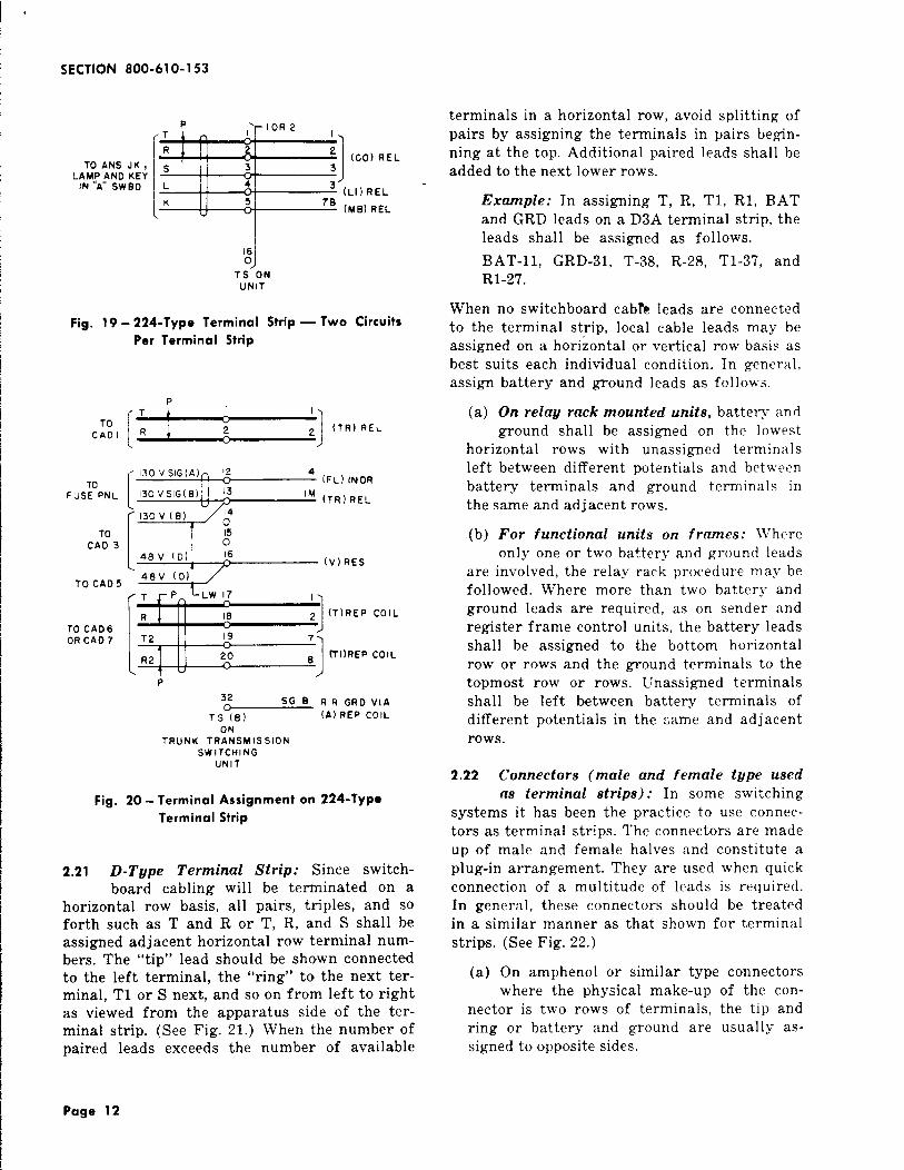
Fig. 19- 224-Type Terminal Strip — Two Circuits
Per Terminal Strip
P
[f
T I
TOcAoi R 2 2
‘1
(TR) REL
[
130 VSIG(A)n 12 4(FL) IF.JDR
FuSE PNL 130 VSIG(B) 1<‘M (T R)RELu
[1 ‘;
130v (B) 143
TO 15CAD 3 0
4BV (D) 16(v)REs
TO CADS48V (D)
‘:’”[s
Tp LW 17
R 181
~ (T)REp COIL
T2 19 7
R2 20 1*(TI)REP COIL
P
32 SG B R R GRo vlA
TS (E) {A) REP COIL
ONTRUNK TRANSMISSION
SWITCHINGUNIT
Fig. 20- Terminal Assignment on 224-Type
Terminal Strip
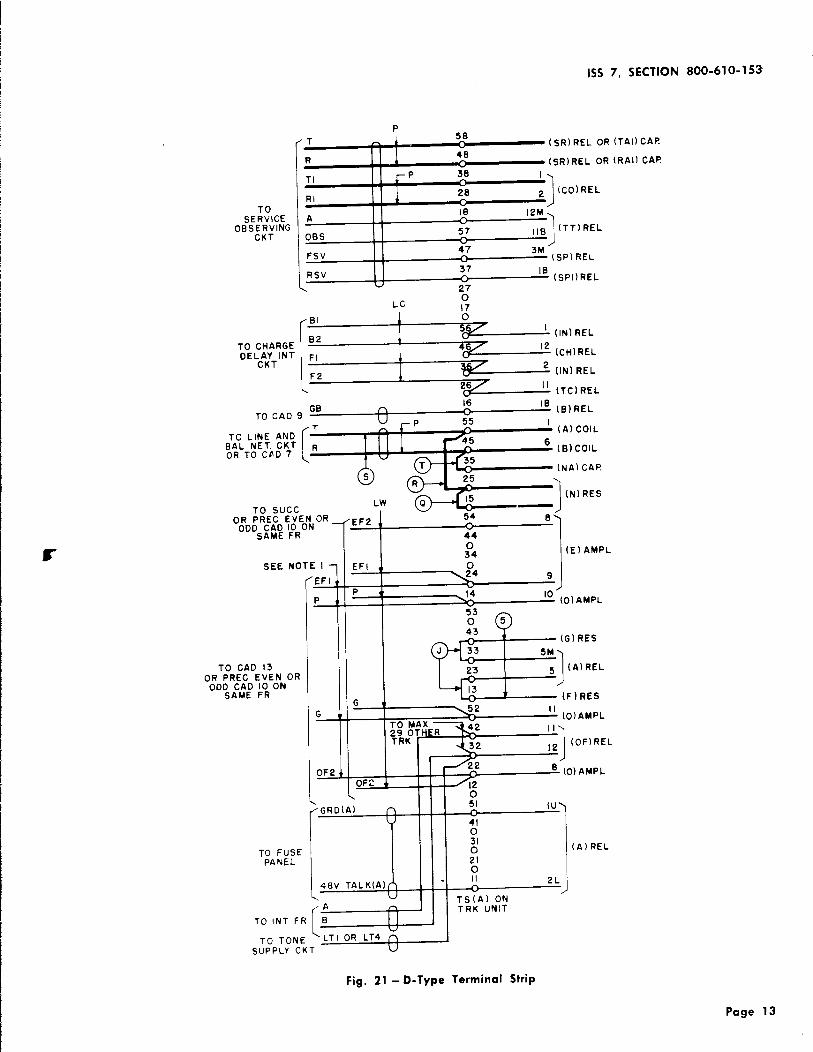
2.21 D-Tgpe Terminal Strip: Since switch-board cabling will be terminated on a
horizontal row basis, all pairs, triples, and soforth such as T and R or T, R, and S shall beassigned adjacent horizontal row terminal num-bers. The “tip” lead should be shown connectedto the left terminal, the “ring” to the next ter-minal, T1 or S next, and so on from left to rightas viewed from the apparatus side of the ter-minal strip. (See Fig. 21. ) When the number ofpaired leads exceeds the number of available
terminals in a horizontal row, avoid splitting ofpairs by assigning the terminals in pairs begin-ning at the top. Additional paired leads shall beadded to the next lower rows.
Example: In assigning T, R, Tl, RI, BATand GRD leads on a D3A terminal strip, theleads shall be assigned as follows.
BAT-11, GRD-31, T-38, R-28, T1-37, andRI-27.
When no switchboard cabte leads are connectedto the terminal strip, local cable leads may beassigned on a horizontal or vertical row basis asbest suits each individual condition. In general,assign battery and ground leads as follows.
(a) On relag rack mounted units, battery andground shall be assigned on the lowest
horizontal rows with unassigned terminalsleft between different potentials and betweenbattery terminals and ground terminals inthe same and adjacent rows.
(b) For functional units on frames: 11’hereonly one or two battery and ground leads
are involved, the relay rack procedure may befollowed. Where more than two battery andground leads are required, as on sender andregister frame control units, the battery leadsshall be assigned to the bottom horizontalrow or rows and the ground terminals to thetopmost row or rows. Unassigned terminalsshall be left between battery terminals ofdifferent potentials in the ~ame and adjacentrows.
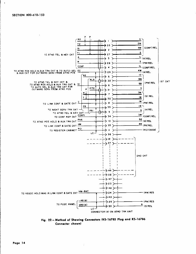
2.22 Connectors (male and female t~pe used
as terminal strips): In some switchingsystems it has been the practice to use connec-tors as terminal strips. The connectors are madeup of male and female halves and constitute aplug-in arrangement. They are used when quickconnection of a multitude of leads is required.In general, these connectors should be treatedin a similar manner as that shown for terminalstrips. (See Fig. 22. )
(a) On amphenol or similar type connectorswhere the physical make-up of the con-
nector is two rows of terminals, the tip andring or battery and ground are usually as-signed to opposite sides.
Page 12
1SS 7, SECTION 800-610-153
TOSERVICE
OBS:::ING
P
(
T i5B
.
11
(sR)REL oR
R48
(sR)REL OR
TI ~P 38
RI 128
‘)
~ (co)REL
A10 12M
OBS57“ 1
,,B (T T)REL
FSV47 3M
(5P) REL
[RSV I 37 10
u(s PI)REL
27
LCo17
TO CHARGEOELcA~TINT
(IN) REL
(CH)REL
(IN) REL
(TC)REL
GB16
TO CAD 9n ‘B (B)REL
T~P 55 I
TO LINE AND
[
n (A) COIL
BAL NET. CKT R 1111OR TO Cfi D7
(B) COIL
[N A) CAP
LW
1
1(N1 RES
TO SLICCoR PREC EVEN OR
-1’
EF254 8
ODDS~;~~RON44 1
II o34 I (E) AMPL
SEE NOTE I EFI 1 0
(EFI\24 9
I
TO CAO 13OR PREC EVEN OR
OD;:;: ;:ON
G
q-f=p::
!!
G -2 IIt!
TO MAX.(0)AMPL
II
1
,2 (OF)REL
0F2 t 8 (0)AMPLOft ●
\
“-w-tJ--l48v TALK(A)
T-(xTO TONE
SUPPLY CKT
~151 Iu
410310 (A)REL
210II 2L
:#:No;
-1
(TAI) CAR
(R AI) CAP
Fig. 21 -D-Type Terminal Strip
Page 13
SECTION 800-6” 0-153
PP
EEflE’EM
TI 1’TO ATND TEL 8 KEY CKT 27
A 3
H28
CONF 4
T7#TO ATND POS HOLD 8AUX TRK CKT 8 TO AUTO-SEL OC
a AUX CKT FOR OUTWARD SERV FROM ATND POS 29
NS
RLS ITO ATNO TEL a KEY CKT 8
TO ATND POS HO LDSAUX TRK CKT a GITO AUTO SEL a AUX TRK CKT FOROUTWARD SERV FROM ATNO POS P PT2
mtRTO LINK CONT a GATE CKT
3
c (“
PA
TO NIGHT SERV TRK CKT PAITO ATND TEL a KEY CKT
TO CONF REP CKTCONFI
TO ATND POS HOLD a AUX TRKCKT
TO LINK CONT a GATE CKT WPcl
TO REGISTER CABINET T 1“1
‘cd ---b
5
30
6
31
7
32
8
33
9
34
10
35
II
36
TO ASSOC HOLDMAG IN LINK
——— — -+12
——— —— l@ 3;
1,
i]I III
II II I1,
1
>:
2M
> 1
~ ‘cONF]REL
>I
5 (PW)REL1
>I
‘L (cONF)RELI
>I
‘M (H)REL,
>:10
>8M
I
II>
>iI )Se (PW)REL
3
>I 3M
I\ 1 1
,M (S) REL
/, /> ‘M (PW)REL,
>!IM
> )s (H)REL
I /
) 3M (CONFI REL,
>! 5B(H) REL
>;‘M (PA)REL
>; (PCI) DIOOE
A-)4––---1y:__–––
I
I
III
I
I
I——— — –1-+46>1— ——— —
——— —— +++---––,-+ 47 +
+23 >-
-1-+ 48)-
2ND CKT
HM-BATl“”
CONT a GATE CKT
=i~
- (PW)RES
+:+
(
-48(A)25 (PW) RES
TO FUSE PANEL GRo(A) A50 (S) REL
LC
CONNECTOR (A) ON ATND TRK UNIT
1ST CKT
Fig. 22- Method of Showing Connectors (KS-16785 Plug and KS-16786
Connector shown]
Page 14

1SS 7, SECTION 800-610-153
(1) Ring leads arc connected to numberedpins, I, 2, 3, etc, and the nlatching tip
leads to the opposite pins.
Example: If on a 50-pln connector the ringlead is on pin 1, the matching tip lead wouldbe on pin 26. (See Fig. 22. )
(~) B~tt,e~y and ground leads are generally
assigned to the higher numbered endof the connector. Opposite potentials are as-signed opposite sides with at least one ter-minal separation between battery and otherleads or two battery leads of different po-tentials.
2.23 66-Type Connecting Blocks: Consideringthe connecting block mounted in the ver-
tical position, paired leads shall be assigned ona horizontal row basis starting with the tip onthe left side. (See Fig. 12. ) Where there are notenough terminals in one horizontal row, thepairs shall be assigned from the top down start-ing with the tip. Wherever possible, separationshould exist between leads of opposite or differ-ent potentials.
v F. Lead and Terminal Designations
2.24 When two or more terminals are asso-ciated with tip and ring, the leads shall be
designated T, R, Tl, Rl, etc. In this case, T andR are assigned to the incoming or originatingpair of tip and ring leads.
2.25 In general, the CAD shows the first cir-cuit. If any wiring is repeated for the
succeeding circuits, this wiring is shown in lightdash lines and designated 2nd Ckt, 3rd Ckt, etc,as required. Avoid the use of Ckt 1, Ckt 2, etc,since the numbering of some circuits starts withO, in which case the 2nd Ckt is actually circuit 1.Fig. 6 shows the condition where the first andsecond circuits are in the same cable and Fig. 23shows a separate cable symbol around the leadsof the second circuit to indicate a conditionwhere odd and even circuits are segregated fromeach other. In Fig. 24 only the first and last ter-minals of succeeding circuits are shown and con-tinuity is indicated by the vertical dash line be-tween them.
2.26 In some cases, rows of similarly desig-nated terminals which are perpendicular
to the fanning strip are identified by showing
the group designation that is stamped on theface of the terminal strip. See designations L,D, JJ’E, and WE OUT in Fig. 23.
SHOW NON 4W
REP CKT
SHOWNON REP
COIL CKl
(T) CAP ~~ IST
(R) CAP. ,j CKT
L—.
7(N)REs 1ST
(N I) CAP. cKT/
IDF
Fig. 23- Identification Designations on Terminal
Strips
_- —- -&----lI 2ND
CKT--—— 2--–-
---- +---- iII 3RD
14 CKT—-—— -----
Fig. 24- Method
Circuits
T S-ON >
UNIT
of Showing Second, Third, Etc,
(224-type terminal strip shown)
2.27 Leads from one circuit to another circuit,or between figures on the same circuit,
shall bear letter designations at the ends of eachlead only when the designations of the asso-ciated termirials differ from the lead designa-tions shown on the schematic. (See Fig. 10.)
Page 15

SECTION 800-610-153
G. Lead Terminations
2.28 The termination of both ends of leadsshall be indicated. Leads t~rminating at
apparatus shotvn on the sarn(’ d}.~ltving shall in-dicate, by me:~ns of the apparatus designationand name, th(, ]Jai’titular piece uf ap]]aratus,when it connt,cts to only {Jn( l)iece of ~~pparatus.lVhen it connects to mor(’ than one piccc of ap-paratus, indicate any one of tht’ pieces of appa-ratus to which it is conn(’cted. l~hile the piece ofapparatus so indicated in thcs(~ cases does notnecessarily have to be that to which the lead isdirectly connected in the actual wiring of theequipment, it is preferable th:,t this piece ofapparatus be the one that is indicated.
2.29
ratusratus
\Yhcn a lead (shop side) may or may notpass through a piece of optional appa-befcre termination, both pieces of appa-should be included as shown in Fig. 25.
@H BTO L
TOLL TRK 4- 61+1
(A) AS SHOWN ON THE FS
TO L n (H) OR (B) RELTOLL TRK TS ON
uNIT
(B) AS SHOWN ON THE CAD
Fig. 25- Method of Showing Lead Termination
Through Optional Apparatus
2.30 Local cable leads connected to two ormore terminals on 22 G and similar-type
terminal strips shall terminate on the higher-numbered or left termin:i] of the group of ter-minals strapped together, as viewed from thewiring side. On existing CAD figures where thispractice ‘S not followed, the feeder lead maybe connected to the higher-numbered terminalin the actual wiring of the equipment.
2.31 Apparatus code numbers are not to beused as a means of identification unless
absolutely necessary. It is preferable to showthe spring and terminal numbers on all leadsbut they may be omitted where desirable. Incases where one spring on a specific relay isspecified and several springs of that relay are
strapped together, the connection may be madeto any one of the (’electrically cf~nitnon termi-nals. Fig, 26 depicts I(acls terminating at [’-typerelays. For wire)-spring r~lays, the nlovahlc twincontact springs shall bc numbered the samv :tstheir associ:ited fixfd sl)rings \\ith the appro-priate suffix 31 (makr) or B (br(ah-).
cROSS CONN
AS SPEC TO“RC’’CAD 250“SC” CAC 260“RP’’CAO 254“RT” CAC 256“CG’’CAC2FJ3‘T R’’CAC 317
is_—\c.—Il——~:,——
‘c,——
‘c
~:——
c—.
GROUP OR SUBGROUP
*NAT’ON
* ,(B T191REL
%+5+’ i
L——
c_—
+4-%
s007 5T
006 3T
005 IT
004 I
78
*
50
30 ~
000 In I
(B
I
I
I
I
I
I
TOO)REL
I c ! 1 .-
/\ — 7s (RGF
A I )
TeRRFR ATO CA C319
‘( SUPL RR BAY)
Fig. 26- Spring and Terminal Numbers
2.32 Leads terminating on apparatus or equip-ment shown on another circuit drawing
shall be grouped, when convenient, in one bracketindicating by notation the connecting circuit. Thelead designations shall correspond to those onthe circuit schematic drawing and connecting cir-cuit.
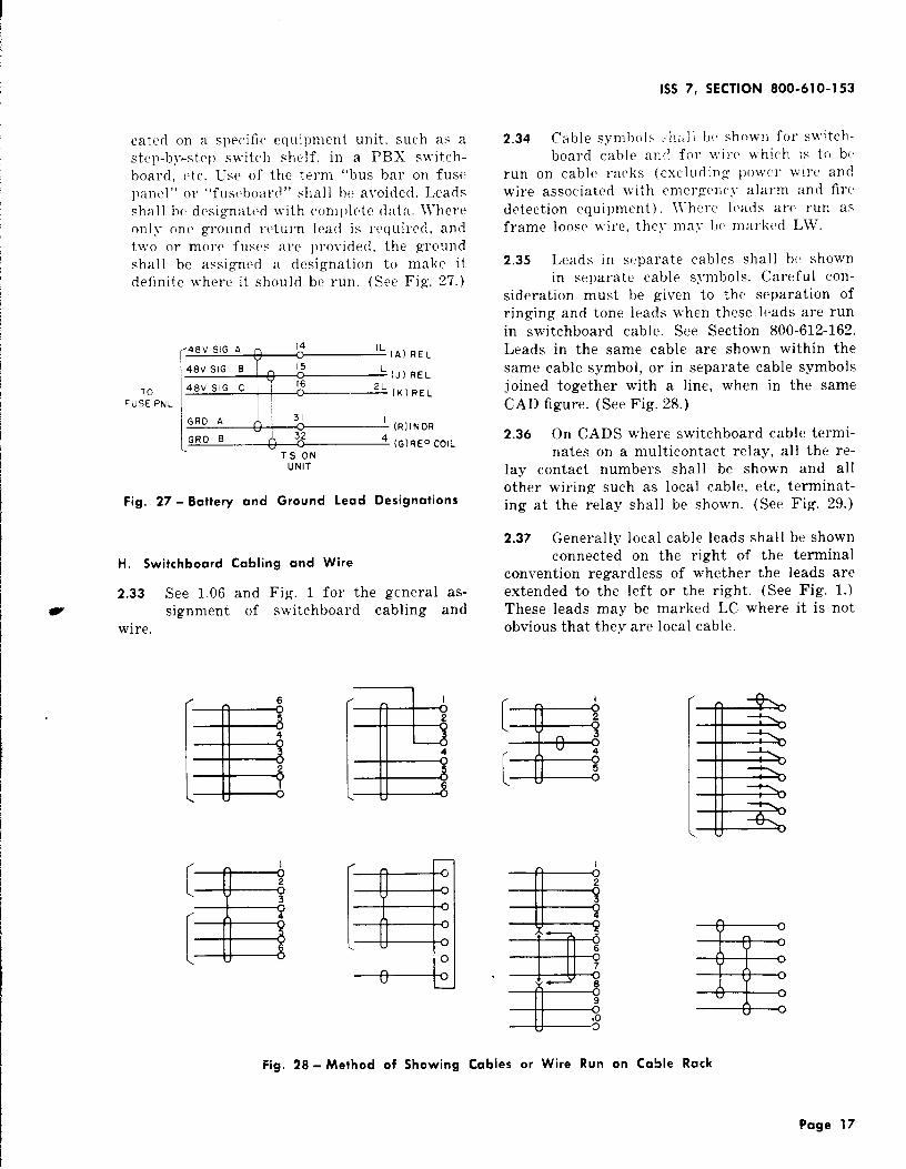
(a) Where no fuse bay is used in an office, thebattery and ground leads for relay rack
units shall be designated “To Fuse l’nl” inall cases except where the fuse panel is lo-
Page 16
1SS 7, SECTION 800-610-153
cated on a specific equipment unit, such as astep-by-step skvitch shelf, in a I’BX s\vitch-board, etc. Use of the term “bus bar on fusepanel” 01 “fust’board” shall be avoided. Leadsshall be designated \vith complete data, ~Yhereonly one ground l-eturn lead is rvquircd, andttvo or more fuses are provided, the gro~lnclshall be assigned a designation to malic itdefinite where it should be run. (See Fig. 27. )
TO
FuSE PNL ‘=qj=:~~GRD A 31
1 (R IINDR
I GRD B A 524 (G) REp COIL
‘T SON
UNIT
Fig. 27- Battery and Ground Lead Designations
H. Switchboard Cabling and Wire
2.33 See 1.06 andz signment of
wire.
Fig. 1 for the generalswitchboard cabling
as-and
[
I
3
[z
4
E2
4
.3=s
.-+--&J
Fig. 28- Method of Showing
2.34 Cable symb~,ls :-h:,]] lJ(i showl~ for switch-board cable and fol ~vi]c which is to bf
run on cable Yaclis (excluding po]vcr \virc andwire associated with emergency alarm and firedetection equipment). 11’hcl’c leads arc run asframe 100SC wire, they may bc marked LW.
2.35 Leads in s{parate cables shall bc shownin separate cable symbols. Careful con-
sideration must be given to the separation ofringing and tone leads when these leads are runin switchboard cable. See Section 800-612-162.Leads in the same cable are shown within thesame cable symbol, or in separate cable symbolsjoined together with a line, when in the sameCAD figure. (See Fig. 28.)
2.36 On CADS where switchboard cable termi-nates on a multicontact relay, all the re-
lay contact numbers shall be shown and allother wiring such as local cable, etc, terminat-ing at the relay shall be shown. (See Fig. 29. )
2.37 Generally local cable leads shall be shownconnected on the right of the terminal
convention regardless of whether the leads areextended to the left or the right. (See Fig. 1.)These leads may be marked LC where it is notobvious that they are local cable.
[
I
E2
3
[
4
5
I
=!E=i2
-s
6
7
8
s
9
103
Cables or Wire Run
Hi=
on Cable Rack
Page 17

SECTION 800-610-153
J
59
3’0
TO FIRST R6DT n 29DECODCR CKT
TOOR
CONTACTSOF (RO)
REL
=kH=#=91(CONI) RCL co’<’
(HMG) REL
(HMG) RE1
TO FIRSTI F.J.JEil~OMLSL
MKR CX~
HMG II I I I 06 I
-(CLCJ I J/ 05c
1AAl/
04A
CHS
L“
u; ‘El
03
CK, CI+9
02
; SK~ CK
01
k
: OKAK 00
AK
TO FIRST TOLL --__J’COMPL MKR CKT
Fig. 29-Switchboard Cable Run Direct to
(A)
Fig. 30- Method
Page 18
Relay
2.38 \Vhen like terminals are multipled to-gether on a geographical basis, that is,
considering physical location rather than thenumbering of circuits, the multiple conventionmay be shown by means of an undesignated stubas shown in Fig. 30 (a), a designated stub asshown in Fig. 30(b), or a limitation on the stubas shown in Fig. 30(c).
2.39 When it is essential that like terminalsare to be multipled together in a nulneri-
cal order for like frames, the multiple con\-en-tion (as shown in Fig. 31) designated “To Pre-ceding Frame” and “To Succeeding Frame” is
used.
[ “’~ ‘A
ATO Z CKT OR B
\
~
FROM PRECEOING B:NLIMI:’ED c
~ (ON)REL
c14
<’ u D ;TS ONY CKT
TO SUCCEEDING dNUMBEREO Y CKT
Fig. 31 - Method af Showing Leads Multipled in
Numerical Sequence
2.40 When it is essential that terminals are tobe connected together as in a series chain,
the leads shall be designated “To Preceding”and “TO Succeeding” circuits as required. (SeeFig. 32.)
1. Wires Functionally Unassigned
2.41 Where certain springs or terminals on263-, 286-, 287-, or similar-type relays and
218-, CA-, BU-, or similar-type terminal stripsare not assigned a circuit function, the switch-board cable leads shall be shown connected tothe unassigned terminals and designated with
TO OTHERBI LEADS ON
SAME UNIT
TO MAX9 }]~E R
I
01
BI -~
(B)
of Shawing Leads Multipled
\
(c)
on a Geographical Basis

1SS 7, SECTION 800-610-153
,,,[ ii --4K=-,(A) G CKT AS SHOWN IN THE FS
F~~;T
“K’[~-l(A)RELG CKTLAST
CKT
;:;:U2-!J(B) G CKT AS SHOWN IN THE CAO
Fig. 32- Method of Showing Leads Connected in a
Series Chain
the terminal number as shown in Fig. 33 exceptwhen circuit operation does not permit this. Theother end of such wiring (and also any multiple
P of this wiring through intervening apparatus)shall, in general, show the switchboard cableterminated as follows.
(a) At other 263-, 286-, and 287-type relaysO1.218-, CA- Or B~T-type termina] strips,
show connected as above..(b) At terminal strips having fanning strips,
show connected as above.
(c) At terminal strips, without fanning strips,show terminations for leads assigned a
circuit function only.
(d) At apparatus other than that previouslycovered by this paragraph, show termina-
tions for leads assigned a circuit function only.
J. Cross Connections
2.42 Distributing Frames: In order to avoidcongestion and to facilitate maintenance
on distributing frames, not more than one cross-connection wire shall usually be assigned toeach terminal.
(a) An exception is in the case of cross-con-nections of 4-party lines in step-by-step
offices where the provision of space on the dis-tributing frame for the usual 4-pa:ty bunching
TO hlKR CKTOR TO
LINE LINKCONN FR FOR
SAM EMKR
V4 19 .
E
;0 lb
14 14
13 13
12 12
II
10
09 -y&l
yo8
BS I o~
OF <6
PL ‘~ 05
DTT 7%4
OTK <3
CBK +02
CBB -01
C9G <0u .—
%&TS (B) “
BAR EWIRESTRAPS TO
FIXED CONTACTSOF (MCB) REL
TO OTHER LINELINK CONN FR -!
FOR SAME MKR
Fig. 33- Method of Showing Wires Functionally
Unassigned
blocks is impracticable or not considert)d justi-fiable. This requires the doubling up of thecross-connections of parties 3 and 4 with thoseof parties 1 and 2, respectively.
2.43 Cross Connecting Fields: On common ct}lI-trol cross-connections such as marlier
frames, it is preferable to have one cross-connec-tion per terminal (see Fig. 26) but nlor(’ thanone may be permitted.
2.44 lYhere cross connections may be ternli-nated at one or more of sc,veral locations,
they shall be run to a bracliet desi~gn:~tecl to indi-cate all of the possible terminations. (s,(Fig. 10. ) On detached-contact schematics, a ]“vf-erence to the section on cross-connection infor-mation only is necessar)-.
Example: “Cross-Connect To C’.~D .5, SC{. Note 4.02.”
K. Straps
2.45 The CAD shall show the strap connec-tions on that side of thr terminal strip
on which they actually are to be placed h}- I}IL’
Page 19
SECTION 800-610-153
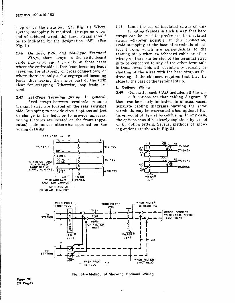
shop or by the installer. (See Fig. 1.) Wheresurface strapping is required, (straps on outerend of soldered terminals) these straps shouldbe so indicated by the designation ‘(SS”. (SeeFig. 4.)
2.46 On 203-, 259-, and 284- Tgpe Terminal
Strips, show straps on the switchboardcable side only, and then only in those caseswhere the entire side is free from incoming leads(reserved for strapping or cross connections) orwhere there are only a few segregated incomingleads, thus leaving the major part of the stripclear for strapping. Otherwise, loop leads areused.
2.47 224-Type Terminal Sf rips: In general,fixed straps between terminals on same
terminal strip are located on the rear (wiring)side. Strapping to provide circuit options subjectto change in the field, or to provide universalwiring features are located on the front (appa-ratus) side unless otherwise specified on thewiring drawing.
SEE NOTE I--I P
TO CAD 2
TO ANN CKT AUOALM a PiLOTLAMP CKT OR
VISUAL ALM CKT
ELL!--JF’RELAORG 4
}
F
DC, MJOR OL 5
A 6
;% ~N7
LW TS ON }
WITH AUD ALM PANELANO PILOT LAMPCKT
(0)REL
.( EII)REL
2.48 Limit the use of insulated straps on dis-tributing frames in such a way that bare
straps can be used in preference to insulatedstraps wherever possible. In this connection,avoid strapping at the base of terminals of ad-jacent rows which are perpendicular to thefanning strip when switchboard cable or otherwiring on the installer side of the terminal stripis to be connected to any of the other terminalsin those rows. This will obviate any crossing orshorting of the wires with the bare strap as thedressing of the skinners requires that they lieclose to the base of the terminal Strip.
L. Optional Wiring
2.49 Generally, each CAD includes all the cir-cuit options for that cabling diagram, if
these can be clearly indicated. In unusual cases,separate cabling diagrams showing the sameterminals may be warranted when optional fea-tures would otherwise be confusing. In any case,the options should be clearly explained by a note’or by option letters. Several methods of show-ing options are shown in Fig. 34.
WITH ANN CKT _jOR VISUAL ALM CUT
S T::l ON
WHEN PROTIS NOT REOO 7
‘BTS ONUNIT
[v“T T(2)
R R(4)
A4
PR
~s B
THRU FILTER WHEN FILTER
UNIT r IS REOD 2W
VERTI
TERM.ON FILTER
u
Ait’UNIT R
,1FILTER BVERT
[1
*2W
_J I----- ----7-1
P
ST::ION[Ld- ----- --. u
vERTL WHEN PROT ~ ~
IS REUI
t
---- JWHEN FILTERIS NOT REQD
CROSS CONNECTTO CENTRAL OFFICE
EQUIPMENT
Fig. 34- Method of Showing Optional Wiring
page 2020 Pages