CABLES AND BUSBAR SYSTEMS - EE&T Lecture Notes Lec03 Cables.… · Separation of power and...
43
ELEC9713 Industrial and Commercial Power Systems CABLES AND BUSBAR SYSTEMS 1. Introduction Electrical power distribution in buildings and industrial sites is achieved primarily by use of cables or busbars. Cables are used for the full range of current levels at low (400/230V) and high voltage (3.3, 6.6 and 11kV). Busbars are mostly used for the very high range of current carrying capacity, usually at medium/low voltage (400/230V). In addition to simple electrical energy supply, cables are also extensively used for control and communications functions in building and industrial sites. The choice of cable voltage for purely electrical energy supply depends on the size of the building or industrial site. Most mains installations will have cable systems operating at 400/230V and busbar systems will also operate at 400/230V. For extensive sites or for large loads the cables may be high voltage, at 11kV in modern sites or at 6.6 or 3.3kV in older sites (mainly industrial). Other types of cable may be used in some more sensitive areas: for example mineral insulated metal sheathed cable (MIMS - Pyrotenax) where fire resistance is required, or simply fire resistant cable which uses mica tape sheaths over the conductor and under the main insulation. ELEC9713: Industrial and Commercial Power Systems p. 1
Transcript of CABLES AND BUSBAR SYSTEMS - EE&T Lecture Notes Lec03 Cables.… · Separation of power and...

ELEC9713 Industrial and Commercial Power Systems
CABLES AND BUSBAR SYSTEMS
1. Introduction Electrical power distribution in buildings and industrial sites is achieved primarily by use of cables or busbars. Cables are used for the full range of current levels at low (400/230V) and high voltage (3.3, 6.6 and 11kV). Busbars are mostly used for the very high range of current carrying capacity, usually at medium/low voltage (400/230V). In addition to simple electrical energy supply, cables are also extensively used for control and communications functions in building and industrial sites. The choice of cable voltage for purely electrical energy supply depends on the size of the building or industrial site. Most mains installations will have cable systems operating at 400/230V and busbar systems will also operate at 400/230V. For extensive sites or for large loads the cables may be high voltage, at 11kV in modern sites or at 6.6 or 3.3kV in older sites (mainly industrial). Other types of cable may be used in some more sensitive areas: for example mineral insulated metal sheathed cable (MIMS - Pyrotenax) where fire resistance is required, or simply fire resistant cable which uses mica tape sheaths over the conductor and under the main insulation.
ELEC9713: Industrial and Commercial Power Systems p. 1
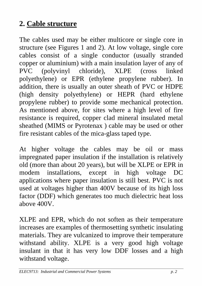
2. Cable structure The cables used may be either multicore or single core in structure (see Figures 1 and 2). At low voltage, single core cables consist of a single conductor (usually stranded copper or aluminium) with a main insulation layer of any of PVC (polyvinyl chloride), XLPE (cross linked polyethylene) or EPR (ethylene propylene rubber). In addition, there is usually an outer sheath of PVC or HDPE (high density polyethylene) or HEPR (hard ethylene propylene rubber) to provide some mechanical protection. As mentioned above, for sites where a high level of fire resistance is required, copper clad mineral insulated metal sheathed (MIMS or Pyrotenax ) cable may be used or other fire resistant cables of the mica-glass taped type. At higher voltage the cables may be oil or mass impregnated paper insulation if the installation is relatively old (more than about 20 years), but will be XLPE or EPR in modem installations, except in high voltage DC applications where paper insulation is still best. PVC is not used at voltages higher than 400V because of its high loss factor (DDF) which generates too much dielectric heat loss above 400V. XLPE and EPR, which do not soften as their temperature increases are examples of thermosetting synthetic insulating materials. They are vulcanized to improve their temperature withstand ability. XLPE is a very good high voltage insulant in that it has very low DDF losses and a high withstand voltage.
ELEC9713: Industrial and Commercial Power Systems p. 2

PVC is an example of the thermoplastic class of synthetic insulation. These materials soften as their temperature increases but regain their original form (but not necessarily their shape) when they cool. Paper insulation is a natural cellulosic fibre which is used in cables with the paper impregnated by a hydrocarbon oil or thick grease type compound. Although the paper in oil composite is a very good insulator, it has some drawbacks in that the cable joints and terminations are much more difficult to make and they must have a metal outer sheath to contain the oil. Multicore cables at low voltage usually have four conductors with three phases and a neutral. They may be either stranded copper or aluminium or, more often, solid section aluminium. The conductors are often sector shaped to give a better packing density in the overall structure. At high voltage the cables will be paper insulated if older style or XLPE or EPR in modern cables. The higher voltage cables will be 3-core, with three main phase conductors and an outer metal sheath as the neutral of earth. EPR insulation is much more flexible than XLPE and is used more often in locations requiring high cable flexibility, such as for trailing cables in underground mines and similar applications. Figures 1 and 2 show some examples of typical cable designs and configurations.
ELEC9713: Industrial and Commercial Power Systems p. 3

Fig.1: single-core, multi-core. ELEC9713: Industrial and Commercial Power Systems p. 4
Figure 2: Examples of LV and HV cables
ELEC9713: Industrial and Commercial Power Systems p. 5
3. Requirements of cable system designs There are some general installation requirements for power cable systems, in addition to the primary selection considerations of rating and voltage. These secondary installation requirements include: Separation of power and control/communication cabling systems to prevent induced interference
Protection of cables from physical damage Use of additional cable ducts to allow for future expansion
Care in the preparation of joints to prevent high contact resistance or low insulation levels
The major considerations to be applied in the selection of cables or busbar systems are: The current carrying capacity [determined by the maximum permissible steady state temperature rise].
The voltage drop and regulation of the cable/busbar circuit at full load
The short circuit rating [determined by the maximum permissible transient temperature rise with fault current]
The insulation requirements and associated factors [jointing and termination: the cable accessories].
The required level of fire resistance of the cable and busbar systems.
ELEC9713: Industrial and Commercial Power Systems p. 6
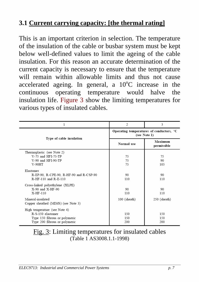
3.1 Current carrying capacity: [the thermal rating] This is an important criterion in selection. The temperature of the insulation of the cable or busbar system must be kept below well-defined values to limit the ageing of the cable insulation. For this reason an accurate determination of the current capacity is necessary to ensure that the temperature will remain within allowable limits and thus not cause accelerated ageing. In general, a 10oC increase in the continuous operating temperature would halve the insulation life. Figure 3 show the limiting temperatures for various types of insulated cables.
Fig. 3: Limiting temperatures for insulated cables
(Table 1 AS3008.1.1-1998)
ELEC9713: Industrial and Commercial Power Systems p. 7

This rating determination must be done for all cables and conductors. For some circuits there is no need to perform detailed calculations as there are specific requirements laid down by regulations for specified cable sizes in various situations. For example, the minimum rating for consumers mains cables is 32A and for sub-mains cables it is 25A. However, above this minimum level the ratings must be calculated with reasonable accuracy. The calculation is complicated by a number of variable parameters which may have a significant effect on the capacity. These parameters include the ambient temperature, the enclosure of the cable (if any), bundling of multiple cables etc. It is usual, and sufficiently accurate in most cases, to use the tables which are given in the Australian Standards AS3000 (The Wiring Rules) and in standard AS3008.1, an accompanying standard to AS3000, to determine the current rating capacity. Tables 3-21 of AS3008.1 give ratings for a variety of cable types and enclosures that cover most usual applications. Figures 4-9 are some typical examples. In the calculations the maximum load demand figures must be used as the basis for cable size determination and some allowance should be made for future expansion, de-rating from mutual heating of bundled cables, any effects of harmonics and frequency of current. Special attention must also be given to the current carrying capacity of the neutral conductor. This is often of smaller cross-section than phase conductors and this can sometimes lead to problems if there are out of balance loads, but particularly if the load is non-
ELEC9713: Industrial and Commercial Power Systems p. 8
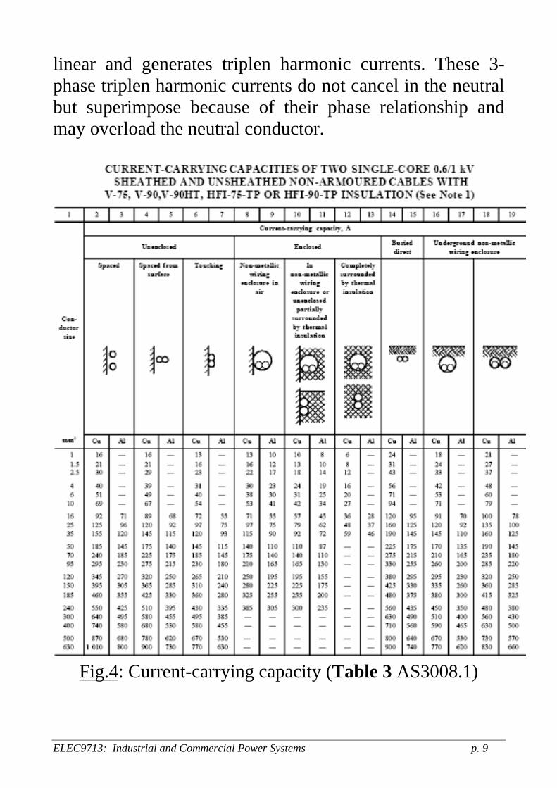
linear and generates triplen harmonic currents. These 3-phase triplen harmonic currents do not cancel in the neutral but superimpose because of their phase relationship and may overload the neutral conductor.
Fig.4: Current-carrying capacity (Table 3 AS3008.1)
ELEC9713: Industrial and Commercial Power Systems p. 9
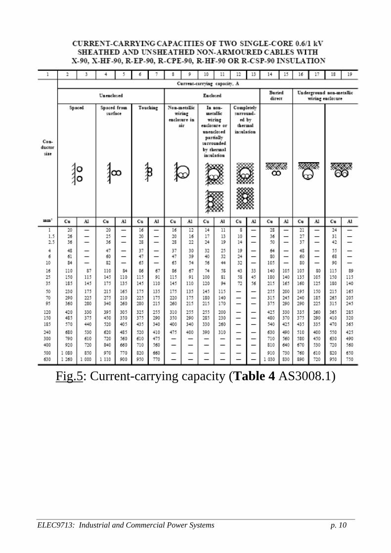
Fig.5: Current-carrying capacity (Table 4 AS3008.1)
ELEC9713: Industrial and Commercial Power Systems p. 10

Fig.6: Current-carrying capacity (Table 9 AS3008.1)
ELEC9713: Industrial and Commercial Power Systems p. 11

Fig.7: Current-carrying capacity (Table 12 AS3008.1)
ELEC9713: Industrial and Commercial Power Systems p. 12

Fig.8: Current-carrying capacity (Table 15 AS3008.1)
Fig.9: Current-carrying capacity (Table 16 AS3008.1)
ELEC9713: Industrial and Commercial Power Systems p. 13

3.2 External influences on cable capacity The current-carrying capacity of a cable can be affected by external influences such as:
Grouping of cables Ambient temperature Depth of laying Thermal resistivity of soil Varying load conditions Effect of thermal insulation Effect of direct sunlight
Thus capacity values given in Tables 3-21 of AS3008.1 should be corrected by applying an appropriate rating factor. A common situation is the grouping of cables in close proximity such that they are not independently cooled by the ambient air or ground. The appropriate de-rating factors are given in Tables 22 to 26 of the Standard.
Fig.10: Cable grouping derating (Table 22 AS3008.1)
ELEC9713: Industrial and Commercial Power Systems p. 14

Fig.11: Cable grouping de-rating (Table 23 AS3008.1)
The current-carrying capacity specified in Tables 3 to 21 of AS3008.1 is based on an ambient air temperature of 40oC and soil temperature of 25oC. If the ambient temperature varies from this standard, the cable capacity needs to be
ELEC9713: Industrial and Commercial Power Systems p. 15

adjusted using the rating factors given in Table 27 of the Standard (see Figure 12 below).
Fig.12: Rating factors for variation in ambient temperature
(Table 27 AS3008.1.1-1998) When calculating voltage drop along a cable the cable conductor resistance is an important factor that be know accurately. However it is dependent on the conductor temperature, so that if the cable current is lower than the maximum rated value (as is likely in most cases), it is necessary to calculate the conductor operating temperature to obtain accurate R values for voltage drop, using R = R20 [1 + α(θ0 – 20)
ELEC9713: Industrial and Commercial Power Systems p. 16
ELEC9713: Industrial and Commercial Power Systems p. 17
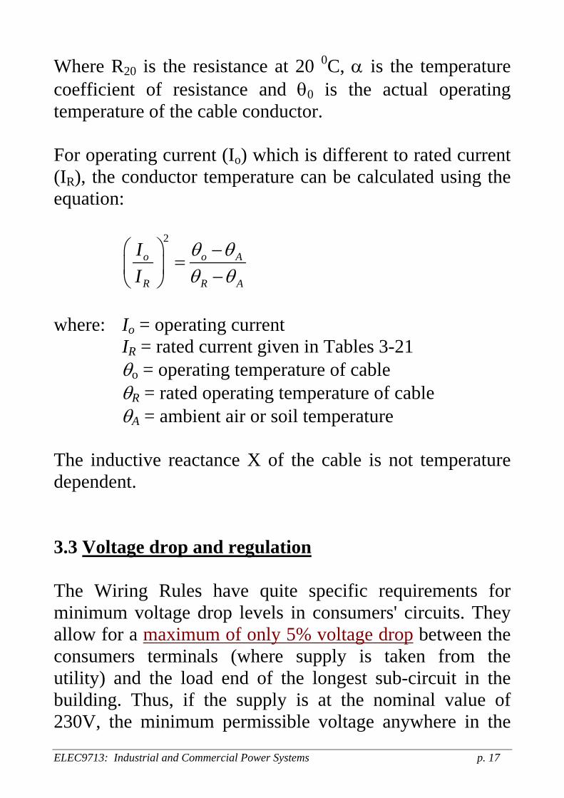
Where R20 is the resistance at 20 0C, α is the temperature coefficient of resistance and θ0 is the actual operating temperature of the cable conductor. For operating current (Io) which is different to rated current (IR), the conductor temperature can be calculated using the equation:
2
o o
R R
II
A
A
θ θθ θ
⎛ ⎞ −=⎜ ⎟ −⎝ ⎠
where: Io = operating current IR = rated current given in Tables 3-21 θo = operating temperature of cable θR = rated operating temperature of cable θA = ambient air or soil temperature The inductive reactance X of the cable is not temperature dependent. 3.3 Voltage drop and regulation The Wiring Rules have quite specific requirements for minimum voltage drop levels in consumers' circuits. They allow for a maximum of only 5% voltage drop between the consumers terminals (where supply is taken from the utility) and the load end of the longest sub-circuit in the building. Thus, if the supply is at the nominal value of 230V, the minimum permissible voltage anywhere in the

consumer's circuit is 218.5V. This is roughly the general lower limit at which most 240V equipment will still operate satisfactorily. There is also a general upper limit of voltage rise of 5% above the supply level. This may occur if some highly capacitive loads are in use. 3.3.1 Allocation of voltage drop in consumer's circuits For a building distribution system, the typical allocation of voltage drop would be as follows:
Consumers mains wiring connections: 0.5 - 1 % Consumers sub-mains wiring connections: 0.75 -1.5% Consumers final sub-circuit connections: 2 - 3 %
The designer must choose and design for allocations from the bands such as to give a total of no more than 5% voltage drop at maximum demand loading. The actual voltage drop (Vd) can be calculated from:
1000
cd
L I VV × ×= volts
where: L = cable length (m) I = current carried by cable (A) Vc = unit of voltage drop (mV/A.m) For a single-phase, two-wire supply system, if using the same conductor type for the active and neutral:
12
1000c
dL I VV φ
× × ×=
ELEC9713: Industrial and Commercial Power Systems p. 18

For a balanced three-phase supply system, no current flows in the neutral. The voltage drop per phase to neutral is voltage drop in one conductor and the voltage drop between phases is therefore:
33
1000c
dL I VV φ
× × ×=
Thus: 1φ voltage drop = 1.155 x 3φ voltage drop 3φ voltage drop = 0.866 x 1φ voltage drop Tables 40-50 of AS3008.1 provide 3φ voltage drop values for various cable configurations, types, conductor size and operating temperatures. If we know cable impedance (Tables 30-39 of AS3008.1) and the load power factor, the voltage drop can be estimated accurately from:
Single-phase: ( )1 2 cos sind c cV IL R Xφ θ θ= ± Three-phase: ( )3 3 cos sind c cV IL R Xφ θ θ= ± Note that the voltage drop will depend on the following factors:
power factor, current level, cable or conductor resistance, temperature effect on resistance inductive reactance, length.
ELEC9713: Industrial and Commercial Power Systems p. 19

Fig.13: three-phase voltage drop (Table 41 AS3008.1)
ELEC9713: Industrial and Commercial Power Systems p. 20

Fig.14: three-phase voltage drop (Table 42 AS3008.1)
For unbalanced 3φ circuits, voltage drop calculations can be performed on a 1φ basis by geometrically summing the voltage drop in the heaviest loaded phase and the voltage drop in the neutral conductor. Another approach would be to assume balanced 3φ load conditions and perform calculations using the current flowing in the heaviest loaded phase.
ELEC9713: Industrial and Commercial Power Systems p. 21

Fig.15: three-phase voltage drop (Table 47 AS3008.1)
3.3.2 Power factor correction In some cases of low factor loads (less than about 0.9) it may be necessary (to satisfy utility requirements) to install power factor correction equipment to limit current and hence voltage drop. It will also decrease the cost of the supply utility charge for power in most cases.
ELEC9713: Industrial and Commercial Power Systems p. 22
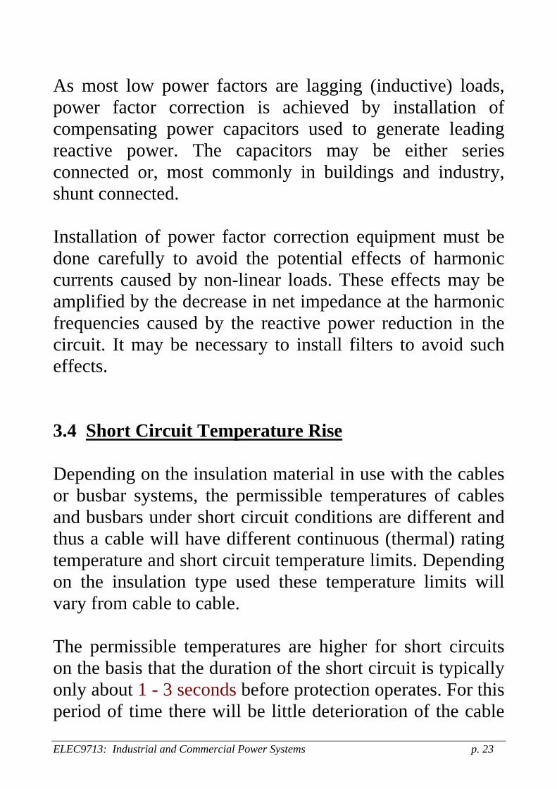
As most low power factors are lagging (inductive) loads, power factor correction is achieved by installation of compensating power capacitors used to generate leading reactive power. The capacitors may be either series connected or, most commonly in buildings and industry, shunt connected. Installation of power factor correction equipment must be done carefully to avoid the potential effects of harmonic currents caused by non-linear loads. These effects may be amplified by the decrease in net impedance at the harmonic frequencies caused by the reactive power reduction in the circuit. It may be necessary to install filters to avoid such effects. 3.4 Short Circuit Temperature Rise Depending on the insulation material in use with the cables or busbar systems, the permissible temperatures of cables and busbars under short circuit conditions are different and thus a cable will have different continuous (thermal) rating temperature and short circuit temperature limits. Depending on the insulation type used these temperature limits will vary from cable to cable. The permissible temperatures are higher for short circuits on the basis that the duration of the short circuit is typically only about 1 - 3 seconds before protection operates. For this period of time there will be little deterioration of the cable
ELEC9713: Industrial and Commercial Power Systems p. 23
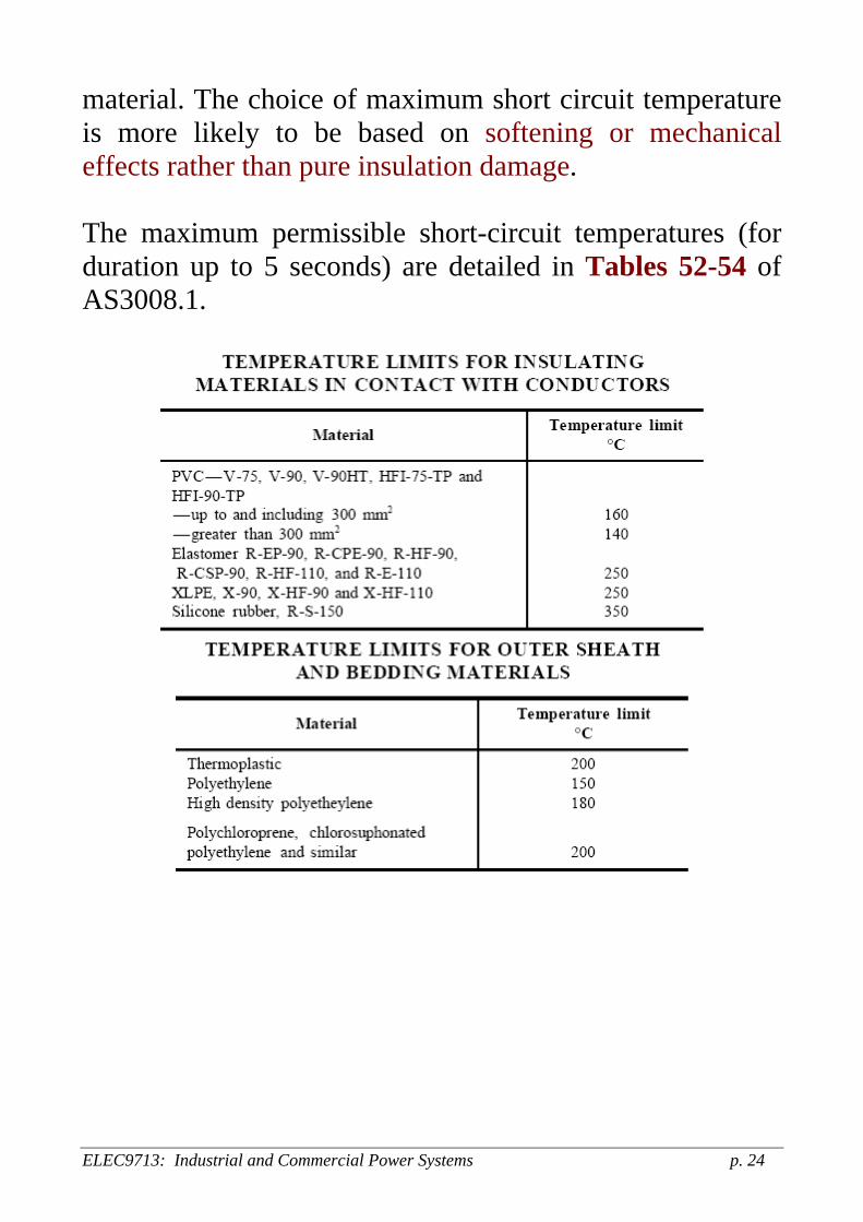
material. The choice of maximum short circuit temperature is more likely to be based on softening or mechanical effects rather than pure insulation damage. The maximum permissible short-circuit temperatures (for duration up to 5 seconds) are detailed in Tables 52-54 of AS3008.1.
ELEC9713: Industrial and Commercial Power Systems p. 24
ELEC9713: Industrial and Commercial Power Systems p. 25
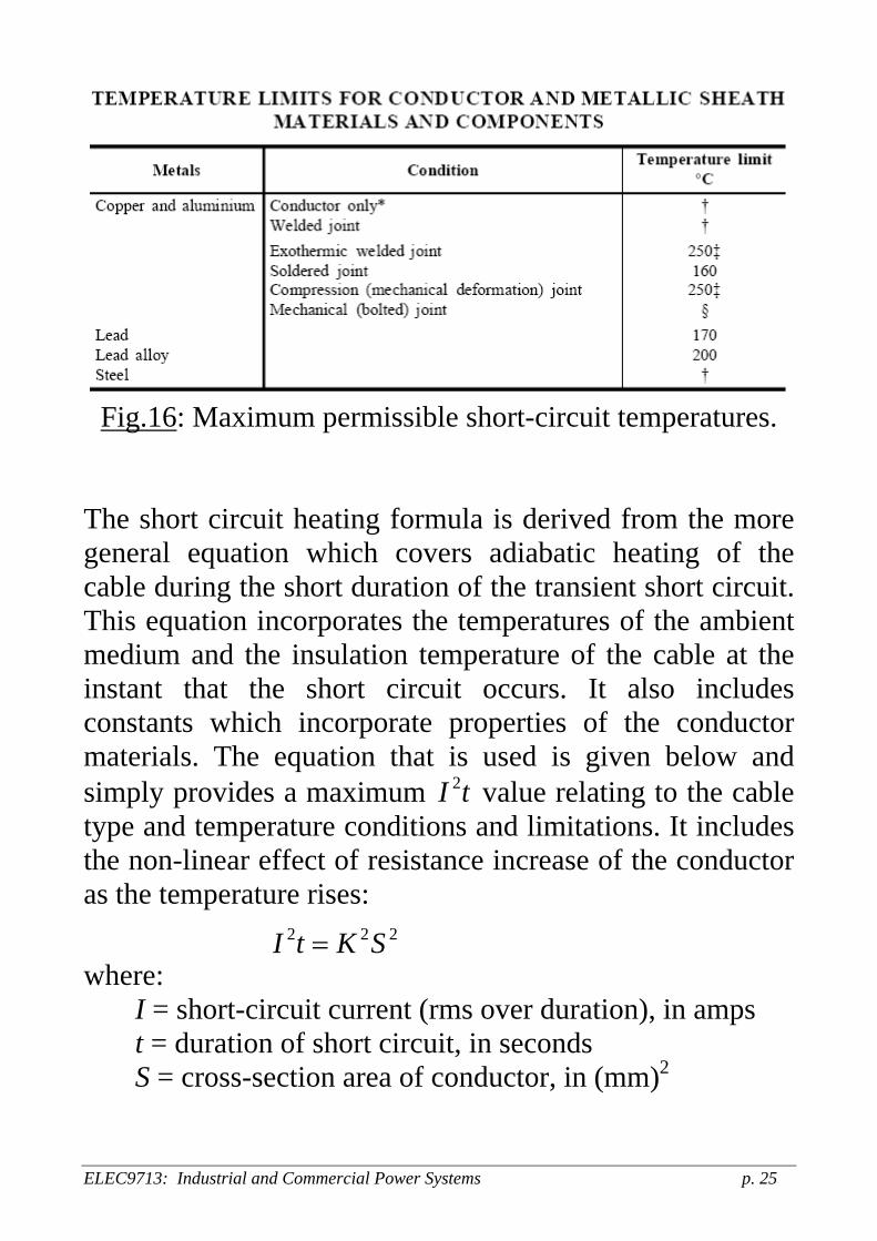
Fig.16: Maximum permissible short-circuit temperatures.
The short circuit heating formula is derived from the more general equation which covers adiabatic heating of the cable during the short duration of the transient short circuit. This equation incorporates the temperatures of the ambient medium and the insulation temperature of the cable at the instant that the short circuit occurs. It also includes constants which incorporate properties of the conductor materials. The equation that is used is given below and simply provides a maximum value relating to the cable type and temperature conditions and limitations. It includes the non-linear effect of resistance increase of the conductor as the temperature rises:
2I t
2 2I t K S= 2
where: I = short-circuit current (rms over duration), in amps t = duration of short circuit, in seconds S = cross-section area of conductor, in (mm)2
ELEC9713: Industrial and Commercial Power Systems p. 26
( ) ( ) ( )20 1 01 20 ln 1 1K cδ α ρ α θ α θ⎡ ⎤ ⎡= + + +⎣ ⎦ ⎣ ⎤⎦
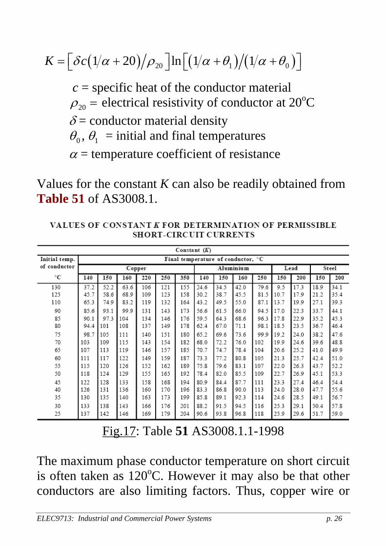
c = specific heat of the conductor material 20ρ = electrical resistivity of conductor at 20oC δ = conductor material density 0θ , 1θ = initial and final temperatures α = temperature coefficient of resistance Values for the constant K can also be readily obtained from Table 51 of AS3008.1.
Fig.17: Table 51 AS3008.1.1-1998
The maximum phase conductor temperature on short circuit is often taken as 120oC. However it may also be that other conductors are also limiting factors. Thus, copper wire or
tape screens have a limiting temperature of 350oC, lead sheath of 200oC and aluminium sheath of 200oC. And in some cases these may be the limiting factor if the return fault current passes through the sheath, say, which may have a higher resistance that the main conductor and thus generate mare heating. For some multicore cables, it may be electrodynamic forces between the phase conductors rather than thermal constraints that determine the short current rating of such a cable. In such cases, a current limitation of the fault level by HRC fuse rather than an I2t limitation is required. 3.5 Insulation Effects The particular type and thickness of insulation of cables and conductors will depend on the voltage of operation and also on the application. For modern high voltage distribution systems, XLPE is almost exclusively used. For low voltage applications, there are many insulation types in use. These include:
PVC XLPE Elastomeric (ethylene propylene rubber [EPR]) Mineral insulated (MIMS)
ELEC9713: Industrial and Commercial Power Systems p. 27

Other factors that need to be considered in the insulation choice are flexibility, hardness, resistance to mechanical effects, effects of moisture and contamination etc. A major factor in the choice of insulation used is the effects of fire on the cable insulation. 3.6 Fire behaviour There are many problems generated by the potential damage to cables which are involved in fires. The fires may be either self-generated, by the cable, or externally- generated but causing significant damage to the cable insulation. The problems that arise are:
1. The cables may provide substantial flammable material in the chemical structure of their insulation
2. They generate significant smoke and soot when they burn and this can cause considerable damage to equipment otherwise unaffected by the fire heat.
3. Many of the fire products from insulation combustion are toxic and thus represent a significant health hazard.
4. Many products of the insulation combustion are corrosive and can substantially damage electronic equipment for example.
5. The cables should ideally be able to operate after significant damage by a fire: however this is not possible if the polymeric insulation burns away: there may be total loss of insulation integrity in this case.
ELEC9713: Industrial and Commercial Power Systems p. 28

The last problem is a particularly important consideration in buildings where power may be required during and after a fire to operate emergency equipment. Thus there is a requirement for fire-resistant cables in buildings and many circuits within a building, particularly high rise buildings, will be designated to have such cabling installed. Item 4 above is an increasingly important aspect because of the large penetration of computers and general electronic and communications equipment in modem commercial buildings. The major problem in this situation is with PVC which generates very large amounts of hydrogen chloride gas when it burns and this can cause havoc with metal in electrical and electronic circuits, particularly when moisture resulting from fire hose and extinguisher use is present. The HCl is also very injurious to health. The response to this problem has been the development of a range of cables able to withstand the effects of fires or able to maintain insulation integrity after a fire. These will be outlined in the next section. In some cases, PVC has been banned for use in buildings and similar areas for general distribution. 4 Cable Types in Use The cable types in use in the overall building supply context are:
ELEC9713: Industrial and Commercial Power Systems p. 29

4.1 Aerial cables or lines These are used between buildings in site complexes or as service lines to buildings. The bare lines with no insulation covering use aluminium or copper or (less likely for buildings) ACSR (Aluminium conductor with steel reinforcement). The insulated overhead cables (which may be either aerial bundled cables (ABC) or simply covered conductors) are installed as either an aerial service line type of application or in some case are mounted on the side fascia of buildings. The insulation may be PVC or some other material which has been treated to be able to withstand the effects of UV radiation. UV radiation from sunlight causes degradation of insulation and is the primary problem with polymeric insulation when used outdoors. ABC can be high voltage (up to 11kV) but the simple covered conductors are always low voltage cables. 4.2 Indoor distribution cables For main circuits these may be either single core or 3-core or 4-core. The insulation may be paper (unlikely in new installations) or XLPE, PVC, elastomer (EPR) etc. at low and medium voltage. The multi-core conductor types may be stranded cores, sector cores, with or without neutral or armour. Typically they will have PVC or PE outer sheathing for protection.
ELEC9713: Industrial and Commercial Power Systems p. 30
4.3 Fire Resistant cables Fire resistant cables are required in specific situations where emergency supply needs to be maintained even in the event of severe fire interaction with the cable. Such cables need to be able to supply power up to two hours after being engulfed in conflagrations. Some common types of such fire resistant cables are described below: 4.3.1 MIMS
Mineral insulated metal sheathed. Single or multi core. The insulant is magnesium oxide powder. There is an outer copper sheath. The powder is not as good an electrical insulant as the normal cable polymeric materials but is able to withstand extreme fire temperatures (700 – 800oC) without any damage. Sealing of the metal sheath must be done carefully to prevent moisture ingress as this will destroy the insulation integrity of the powder. 4.3.2 Radox
This has a glass-mica tape layer wound over the insulation. The insulation is a polyolefin material and is halogen-free to prevent the production of chemically active and toxic halogen based by-products from the fire. 4.3.3. Firestop
This has a mica glass tape wound over the conductor. The insulation is XLPE. Firestop uses halogen-free insulation.
ELEC9713: Industrial and Commercial Power Systems p. 31
Fire resistant cables must be tested to resist the effects of fires. This is particularly the case with the last two types where there is substantial loss of polymer in the fire, leaving only the mica glass tape as the insulant. The test involves exposure to fire at about 1000oC for three hours with the cores live. No short circuits can occur. This is followed by removal from the oven and subjecting the burnt cables to a water spray test to simulate the effect of fire extinguishers. Again, no short circuit can occur if the cable is to pass the test. 4.4 Other cable types There are many other cables in use in buildings, primarily of the communications type. These will be discussed at a later lecture. As stated earlier it is necessary to segregate the communications/control cables from power cables to prevent EM coupling effects which may lead to incorrect information transfer. 4.5 Magnetic interference from cables A recurring and increasing problem with power cables is the effect of the magnetic field generated by the power frequency current in such cables. There are two major areas of concerns in buildings: interference with IT equipment (e.g. computer terminals) and the less tangible one of the potential hazard to personnel. The end result is that some care must be exercised in location and arrangement of
ELEC9713: Industrial and Commercial Power Systems p. 32

cables to minimise these effects. This aspect will be covered later in the course. 5 Cable Enclosures and Conduits These include the following types of enclosure systems: (they should all be halogen-free, if made of insulating material, for fire damage minimisation)
Conduits: steel, rigid PVC, corrugated flexible PVC Tubes and pipes: metal, non-metal plastic, earthenware etc
Ducts: metal or non-metal Cable support systems: cable trays, cable ladders troughs etc
Trunking systems: mainly for busbars. In the case of metal enclosures or support systems, the potential for eddy current heating must be taken into account. Insulation of sections may be necessary to prevent this effect. Also the enclosures may need to be earthed to prevent problems of electric shock by indirect contact if a fault occurs by insulation failure to the metal enclosure. The conduits and other enclosures must have appropriate IP numbers to prevent ingress of moisture and dust to susceptible areas. Some care must also be given to a determination of the impact of the enclosure on the thermal dissipation from the cables and the effect that this will have on the cable rating.
ELEC9713: Industrial and Commercial Power Systems p. 33

It will often be necessary to de-rate the cable current carrying capacity because of thermal limitations caused by enclosures. 6 Busbars and busbar trunking systems (BTS) etc 6.1 Busbars For very high current capacity systems it is common to use rigid busbar systems of either aluminium or copper rectangular section [See Figure 13]. These are normally segmented (laminated) for very high ratings. This 'lamination' achieves two purposes: one is to improve heat loss by providing greater surface area for thermal dissipation and the other is to limit increase of resistance due to skin effect. Both skin effect and proximity effect are significant problems that must be considered for high current AC busbar systems. The segmentation or lamination of the individual phase conductors limits the eddy current generation level which is the basis of the skin and proximity effects in AC conductors. DC systems are not affected in this way and thus only require such segmentation to assist with improving thermal dissipation. The orientation of the busbar sections can have a very significant effect on the thermal dissipation by virtue of the impact on natural convection flows set up in the ambient air and this will affect the current carrying capacity of the bars. Similarly, a matt (non-shiny) surface with a high radiative
ELEC9713: Industrial and Commercial Power Systems p. 34

emissivity will also enhance the current rating substantially through increasing the radiative heat loss. Busbars are prone to potential resonance effects caused by the electrodynamic forces between the conductors. Because of the very small spacing at low voltages and the high currents, the forces on busbars even at normal operating conditions can be significant. With the busbar support being normally at spaced intervals of perhaps a metre or two, the busbar acts as a fixed beam under the lateral electrodynamic force and it will thus have a natural resonant frequency, the value of which will depend on the spacing of the supports, the size of the conductor and the elasticity coefficient of the material. It is a necessary requirement to calculate this natural frequency of resonance and if it is close to the 100 Hz frequency of the electrodynamic forces generated, then the support spacing must be altered to change the resonant frequency to move it further away from the electrodynamic force frequency. The bars may be insulated or uninsulated, although the modem trend in large buildings is for insulated bus bars, often in a trunking system (busbar trunking system [BTS]).
ELEC9713: Industrial and Commercial Power Systems p. 35

Fig.18: Current-carrying capacity of busbars.
ELEC9713: Industrial and Commercial Power Systems p. 36

6.2 Busbar Trunking systems The trunking system consists of a tightly packaged sandwich of the three busbars and the neutral, with an insulating foil (melinex typically) between layers. It may require external fins for cooling because of the densely packed nature of the sandwich. They will also require some protection against ingress of moisture as this can be taken by capillary action to the live conductor and create a creepage path. Trunking systems are now being used with structures which are able to be joined with relative ease to connect plug-in systems. Feeder BTSs can have ratings from a few hundred amps to 10,000 amps. Plug-in systems can have ratings from about 100 amps up to 1500 amps. The outer metal enclosure must be earthed and the same precautions for eddy currents must be taken as in metal bus bar enclosures. They must be type tested and routinely tested before installation. Tests must look at, in particular, the following aspects:
Temperature rise at rated load Short circuit temperature rise Clearances Creepage paths IP ratings Mechanical strength etc.
ELEC9713: Industrial and Commercial Power Systems p. 37

6.3 Flexible copper straps In addition to the rigid trunking systems, flexible insulated copper straps are now being used. These have the advantage of being able to be easily shaped on site to match the installation requirements. They can be used in small switchboards for example where space is limited.
ELEC9713: Industrial and Commercial Power Systems p. 38

Example 1:
Assume: 3φ voltage drop in consumer mains: Vd = 3V balanced loads, i.e. disregard current in neutral Subcircuits wired with multi-core V-75 insulated and sheathed copper conductors, installed in single circuit configuration, unenclosed in air, clipped to a wall. Choose conductor size to satisfy voltage drop requirement. Three-phase circuit: 30A load. From Table 12 column 4, conductor size of 6mm2 has current-carrying capacity of 37A.
Total maximum permissible voltage drop: 5% 400 = 20V×
Hence, voltage drop allowed in 3φ final subcircuit: 20 3 17V− =
Maximum unit value of voltage drop:
1000 1000 17 6.3mV/A.m90 30
dc
VVL I
×= = =
× ×
ELEC9713: Industrial and Commercial Power Systems p. 39

Select Table 42 for multicore cables with copper conductors. Select 75oC column for normal operating temperature of V75 cables. The nearest lower unit value is 3.86mV/A.m. From column 1, this corresponds to cable size of 10mm2. Single-phase circuit: 30A load. From Table 9 column 4, conductor size of 4mm2 has current-carrying capacity of 34A.
Total maximum permissible voltage drop: 5% 230 = 11.5V×
Hence, voltage drop allowed in final subcircuit: ( )11.5 3 3 9.77V− =
Maximum unit value of voltage drop:
1000 1000 9.77 3.62mV/A.m90 30
dc
VVL I
×= = =
× ×
Convert to three-phase value: 3 1 0.866 3.62 0.866 3.14mV/A.mc cV Vφ φ= × = × = Select Table 42 for multicore cables with copper conductors. Select 75oC column for normal operating temperature of V75 cables. The nearest lower unit value is 2.43mV/A.m. From column 1, this corresponds to cable size of 16mm2. Note: in both final subcircuits, cable size had to be increased to comply with voltage drop requirements.
ELEC9713: Industrial and Commercial Power Systems p. 40

Example 2: Underground 1500A 3φ supply is constructed using parallel circuits of 400mm2 V-75 single-core insulated and sheathed Cu cables. Determine the minimum number of active conductors required. (a) All cables in one conduit
Capacity of one 400mm2 cable= 510A (Table 6, col. 16) Refer to Table 22 for derating factor:
510 5 0.6 1530A× × =
(b) Groups of conduits
Refer to Table 26(2) for derating factor:
510 4 0.79 1612A× × =
ELEC9713: Industrial and Commercial Power Systems p. 41

Example 3: 3-φ circuit is to supply a load of 125A per phase. Use two V-75 four-core Cu conductor, insulated and sheathed cables bunched together on a surface in a confined ceiling space where ambient temperature is 50oC. Determine minimum conductor size and maximum route length if allowable voltage drop is 3%. Derating factor for cable bunching = 0.8 (Table 22, col.5) Derating factor for 50oC ambient = 0.82 (Table 27.1, col.9) Required minimum current-carrying capacity:
1 1125 190.5A0.8 0.82
× × = for two parallel cables
or 95.25A per cable. From Table 12, column 4, the conductor minimum size is 35mm2. 3-φ permissible voltage drop: V 400 0.03 12Vd = × = Unit voltage drop (Table 42): V 1.11 mV/A.mc = Maximum route length:
1000 1000 12 173m62.5 1.11
d
c
VLI V
× ×= =
× ×
ELEC9713: Industrial and Commercial Power Systems p. 42

Example 4: 1-φ circuit comprised of two 16mm2 Cu single-core sheathed cable, V-75 insulation, installed unenclosed on a wall. Circuit is to supply 55A resistive load. Determine 1-φ voltage drop value when ambient air temperature is 40oC and 25oC. Operating current 55AoI =From Table 1, rated operating temperature o75 CRθ = From Table 3, current-carrying capacity is . 72A=RI (a) Ambient temperature o40 CAθ =
2
o o A
AR R
II
θ θθ θ
⎛ ⎞ −=
−⎝ ⎠⎜ ⎟ ⇒ operating temperature o60.4 Coθ =
Use o60 Coθ = then from Table 41: 3φ voltage drop = 2.32 mV/A.m thus 1φ voltage drop 1.155 2.32 2.68= × = mV/A.m (b) Ambient temperature o25 CAθ = From Table 27, correction factor = 1.21
2 2555
72 1.21 75 25oθ −⎛ ⎞ =⎜ ⎟× −⎝ ⎠
⇒ o44.9 Coθ =
Use o45 Coθ = then from Table 41: 3φ voltage drop = 2.20 mV/A.m thus 1φ voltage drop 1.155 2.20 2.54= × = mV/A.m
ELEC9713: Industrial and Commercial Power Systems p. 43


![lec03 feature.ppt [相容模式]](https://static.fdocuments.us/doc/165x107/6241df4175df7937e76cfeb3/lec03-.jpg)