Cable Tray - Steel - TNB.COMtnblnx3.tnb.com/emAlbum/albums//us_resource/express_tray.pdf© 2003...
37
Overview . . . . . . . . . . . . . . . . . . . . . . . . . . I2 - I3 U-Profile . . . . . . . . . . . . . . . . . . . . . . . . . . I4 - I7 C-Profile . . . . . . . . . . . . . . . . . . . . . . . . . . I8 - I9 L-Profile and Tools . . . . . . . . . . . . . . . . . I10 - I11 Hardware. . . . . . . . . . . . . . . . . . . . . . . . I12 - I23 Quick Reference . . . . . . . . . . . . . . . . . . I24 - I25 Configuration Methods . . . . . . . . . . . . . . I26 - I29 Support Methods . . . . . . . . . . . . . . . . . . I30 - I35 Finishes and Loading Information. . . . . . I36 - I37 Index . . . . . . . . . . . . . . . . . . . . . . . . . . . . . . . I38 I
Transcript of Cable Tray - Steel - TNB.COMtnblnx3.tnb.com/emAlbum/albums//us_resource/express_tray.pdf© 2003...

Overview . . . . . . . . . . . . . . . . . . . . . . . . . . I2 - I3
U-Profile . . . . . . . . . . . . . . . . . . . . . . . . . . I4 - I7
C-Profile . . . . . . . . . . . . . . . . . . . . . . . . . . I8 - I9
L-Profile and Tools . . . . . . . . . . . . . . . . . I10 - I11
Hardware. . . . . . . . . . . . . . . . . . . . . . . . I12 - I23
Quick Reference . . . . . . . . . . . . . . . . . . I24 - I25
Configuration Methods . . . . . . . . . . . . . . I26 - I29
Support Methods . . . . . . . . . . . . . . . . . . I30 - I35
Finishes and Loading Information. . . . . . I36 - I37
Index . . . . . . . . . . . . . . . . . . . . . . . . . . . . . . . I38
I
Express is for simplicity
Express is for efficiency
Express is for versatility
Express is for flexibility
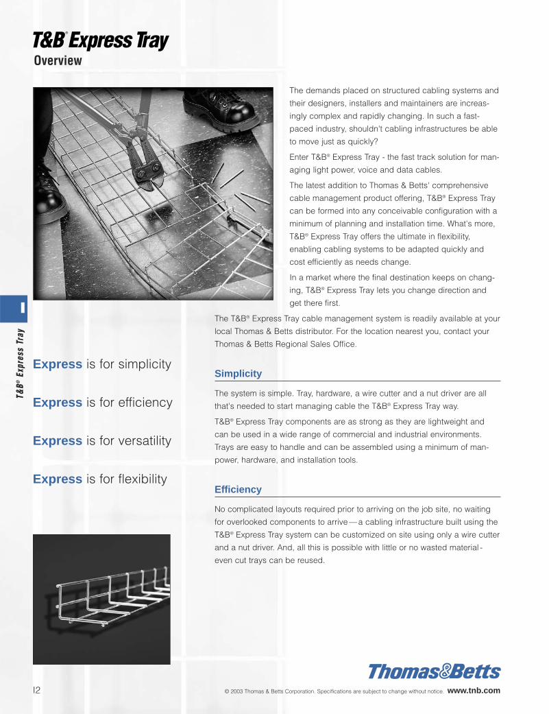
The demands placed on structured cabling systems and
their designers, installers and maintainers are increas-
ingly complex and rapidly changing. In such a fast-
paced industry, shouldn't cabling infrastructures be able
to move just as quickly?
Enter T&B® Express Tray - the fast track solution for man-
aging light power, voice and data cables.
The latest addition to Thomas & Betts' comprehensive
cable management product offering, T&B® Express Tray
can be formed into any conceivable configuration with a
minimum of planning and installation time. What's more,
T&B® Express Tray offers the ultimate in flexibility,
enabling cabling systems to be adapted quickly and
cost efficiently as needs change.
In a market where the final destination keeps on chang-
ing, T&B® Express Tray lets you change direction and
get there first.
The T&B® Express Tray cable management system is readily available at your
local Thomas & Betts distributor. For the location nearest you, contact your
Thomas & Betts Regional Sales Office.
Simplicity
The system is simple. Tray, hardware, a wire cutter and a nut driver are all
that's needed to start managing cable the T&B® Express Tray way.
T&B® Express Tray components are as strong as they are lightweight and
can be used in a wide range of commercial and industrial environments.
Trays are easy to handle and can be assembled using a minimum of man-
power, hardware, and installation tools.
Efficiency
No complicated layouts required prior to arriving on the job site, no waiting
for overlooked components to arrive—a cabling infrastructure built using the
T&B® Express Tray system can be customized on site using only a wire cutter
and a nut driver. And, all this is possible with little or no wasted material -
even cut trays can be reused.
I2 © 2003 Thomas & Betts Corporation. Specifications are subject to change without notice. www.tnb.com
Overview
I
T&B®
Expr
ess
Tray

© 2003 Thomas & Betts Corporation. Specifications are subject to change without notice. www.tnb.com I3
Versatility
T&B® Express Tray requires no corner, crossing or bend
elements. Horizontal bends, vertical bends, drops outs,
T-junctions, crossings, and more—any configuration can
be achieved with a length of tray and a wire cutter. By
simply cutting wires and bending into position, T&B®
Express Tray can meet the most challenging cable lay-
outs and circumvent any mechanical obstacle.
Flexibility
As workplace needs change, the system can easily be
reconfigured to meet new requirements. Whether in new
construction or retrofit projects, T&B® Express Tray's
versatility makes cable routing, management and main-
tenance easier than ever.
Whatever the challenges, T&B® Express Tray has the
power to get the project on track and completed on time
at the minimum installed cost.
Getting started
This catalog is a hands-on guide for selecting,
ordering and using the T&B® Express Tray cable
management system.
Select the profile, width and tray finish required.
Refer to the Quick Reference for an overview of
typical tray configurations and support methods.
Use the Express Tip ( ) references in the
hardware section to locate specific configura-
tions and support methods in which components
are used.
It’s all here. Turn the page to get started.
I
T&B
®Express Tray

(Actual size)
Wire Count
2 50
4 100
6 150
8 200
12 300
16 400
18 450
20 500
24 600
Width Widthin. mm
Width
20˚
2 in.50 mm
2.18
7 in
. / 5
5 m
m 1.18
7 in
.25
mm
2 in.50 mm
2 in.50 mm
2" Deep U-Profile – Low profile for confined spaces
The most frequently specified of the T&B® Express Tray
profiles, the 2" deep U-profile is ideally suited for light- to
medium-duty commercial and industrial applications
where space is at a premium. A low, 2-inch profile has less
wires to cut and minimizes installation time.
— Welded wire-mesh, cable management system made ofhigh mechanical strength steel wire.
— Standard tray length is 10 feet nominal (3 meters actual).
— Mesh measurement of 2" x 4" is standard for all widths of tray except 2".
— Eight (8) tray widths available ranging from 2" to 24".
— Available in electroplated steel, hot-dipped galvanized steel and stainless steel.
— Temperature range-45°C (-49°F) to 150°C (302°F).
— For loading data, refer to the tables on pages 36 and 37 of this catalog.
Network cabling, wiring closets, fiber-to-desktopapplications and more, this tray profile is ofteninstalled in suspended ceiling plenum areas andunder computer room flooring. The 2"-width is espe-cially suited for power and communication drops outof Express Tray™ or conventional ladder tray.
Dimensions
Description Applications
I4 © 2003 Thomas & Betts Corporation. Specifications are subject to change without notice. www.tnb.com
U-Profile
I
T&B®
Expr
ess
Tray

5/32 3.9 ETU 2002SE10 0.43 0.63
5/32 3.9 ETU 2004SE10 0.49 0.72
5/32 3.9 ETU 2006SE10 0.56 0.83
11/64 4.4 ETU 2008SE10 0.86 1.27
11/64 4.4 ETU 2012SE10 1.28 1.89
3/16 4.8 ETU 2016SE10 1.56 2.30
3/16 4.8 ETU 2018SE10 1.70 2.51
3/16 4.8 ETU 2020SE10 1.84 2.71
3/16 4.8 ETU 2024SE10 2.13 3.14
5/32 3.9 ETU 2002SH10 0.44 0.65
5/32 3.9 ETU 2004SH10 0.50 0.74
5/32 3.9 ETU 2006SH10 0.58 0.85
11/64 4.4 ETU 2008SH10 0.87 1.28
11/64 4.4 ETU 2012SH10 1.35 1.99
3/16 4.8 ETU 2016SH10 1.61 2.37
— — — — —
3/16 4.8 ETU 2020SH10 1.91 2.82
3/16 4.8 ETU 2024SH10 2.18 3.21
— — — — —
5/32 3.9 ETU 2004SS10 0.52 0.77
— — — — —
11/64 4.4 ETU 2008SS10 0.72 1.06
11/64 4.4 ETU 2012SS10 0.95 1.40
3/16 4.8 ETU 2016SS10 1.55 2.28
— — — — —
3/16 4.8 ETU 2020SS10 1.86 2.74
3/16 4.8 ETU 2024SS10 2.38 3.51
ELECTROPLATED
Wire Wire Catalog Weight Weightøin. ømm Number lb/ft kg/m
HOT-DIPPED GALVANIZED
Wire Wire Catalog Weight Weightøin. ømm Number lb/ft kg/m
STAINLESS STEEL (Type 304)
Wire Wire Catalog Weight Weightøin. ømm Number lb/ft kg/m
—Low profileprovides flexibility in confined spaces where thereare many obstacles to bypass.
—User-friendlyinstalls in less time than conventional tray with no complex layouts, a minimum of tools and less wasted material.
—Wide range of tray widths2" to 24" widths accommodate as many or as few cables as required.
—2" x 4" mesh sizeallows cables to be routed in or out without cutting wires.
—Open designcontinuous airflow prevents overheating and the build-up of dust and contaminants.
—Chamfered side edgeminimizes risk of injury for installer and damage to cables during installation.
Indoorapplications
Outdoor installations exposed to corrosion accelerators,
indoor applications requiring more corrosion protection.
Applications requiring the maximum corrosion protection,
both indoor and outdoor.
Features
© 2003 Thomas & Betts Corporation. Specifications are subject to change without notice. www.tnb.com I5
U-Profile
I
T&B
®Express Tray
Width
20˚
2 in.50 mm
4.12
5 in
. / 1
05 m
m
1.18
7 in
.25
mm
2 in.50 mm
2 in.50 mm
Wire Count
2 50
4 100
6 150
8 200
12 300
16 400
18 450
20 500
24 600
Width Widthin. mm
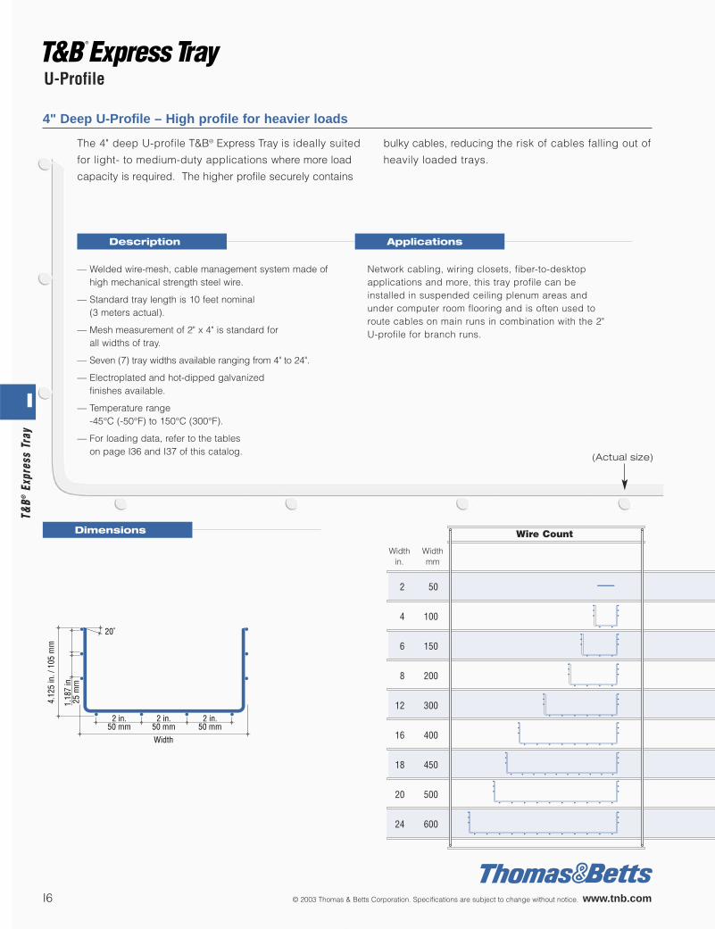
4" Deep U-Profile – High profile for heavier loads
Dimensions
Description Applications
The 4" deep U-profile T&B® Express Tray is ideally suited
for light- to medium-duty applications where more load
capacity is required. The higher profile securely contains
bulky cables, reducing the risk of cables falling out of
heavily loaded trays.
— Welded wire-mesh, cable management system made ofhigh mechanical strength steel wire.
— Standard tray length is 10 feet nominal (3 meters actual).
— Mesh measurement of 2" x 4" is standard for all widths of tray.
— Seven (7) tray widths available ranging from 4" to 24".
— Electroplated and hot-dipped galvanized finishes available.
— Temperature range -45°C (-50°F) to 150°C (300°F).
— For loading data, refer to the tables on page I36 and I37 of this catalog.
Network cabling, wiring closets, fiber-to-desktopapplications and more, this tray profile can beinstalled in suspended ceiling plenum areas andunder computer room flooring and is often used toroute cables on main runs in combination with the 2"U-profile for branch runs.
I6 © 2003 Thomas & Betts Corporation. Specifications are subject to change without notice. www.tnb.com
U-Profile
(Actual size)
I
T&B®
Expr
ess
Tray

— — — — —
5/32 3.9 ETU 4004SE10 0.70 1.03
5/32 3.9 ETU 4006SE10 0.80 1.03
11/64 4.4 ETU 4008SE10 1.13 1.66
3/16 4.8 ETU 4012SE10 1.44 2.12
3/16 4.8 ETU 4016SE10 1.74 2.56
3/16 4.8 ETU 4018SE10 1.89 2.78
3/16 4.8 ETU 4020SE10 2.03 2.99
3/16 4.8 ETU 4024SE10 2.33 3.43
— — — — —
5/32 3.9 ETU 4004SH10 0.72 1.06
5/32 3.9 ETU 4006SH10 0.85 1.25
11/64 4.4 ETU 4008SH10 1.16 1.71
3/16 4.8 ETU 4012SH10 1.47 2.16
3/16 4.8 ETU 4016SH10 1.77 2.61
— — — — —
3/16 4.8 ETU 4020SH10 2.07 3.05
3/16 4.8 ETU 4024SH10 2.37 3.49
— — — — —
— — — — —
— — — — —
— — — — —
— — — — —
— — — — —
— — — — —
— — — — —
— — — — —
ELECTROPLATED
Wire Wire Catalog Weight Weightøin. ømm Number lb/ft kg/m
HOT-DIPPED GALVANIZED
Wire Wire Catalog Weight Weightøin. ømm Number lb/ft kg/m
STAINLESS STEEL (Type 304)
Wire Wire Catalog Weight Weightøin. ømm Number lb/ft kg/m
—Higher profileenhances loading capacity, increases strength for more demanding applications, and prevents cable fallout.
—User-friendlyinstalls in less time than conventional tray with no complex layouts, a minimum of tools and less wasted material.
—Wide range of tray widths4" to 24" widths accommodate as many or as few cables as required.
—2" x 4" mesh sizeallows cables to be routed in or out without cutting wires.
—Open designcontinuous airflow prevents overheating and the build-up of dust and contaminants.
—Chamfered side edgeminimizes risk of injury for installer and damage to cables during installation.
Indoorapplications
Outdoor installations exposed to corrosion accelerators,
indoor applications requiring more corrosion protection.
This profileis not available
in stainless steel.
Features
© 2003 Thomas & Betts Corporation. Specifications are subject to change without notice. www.tnb.com I7
U-Profile
I
T&B
®Express Tray

(Actual size)
2.625 in.67 mm
1.187 in.30 mm
2 in.50 mm
WA
B
2.625 in.67 mm
1.187 in.30 mm
1.187 in.30 mm
1.187 in.30 mm
2 in.50 mm
WA
B
2.625 in.67 mm
1.187 in.30 mm
1.187 in.30 mm
1.187 in.30 mm
WA CC
B
2 in.50 mm
Wire Count
2 50
4 100
6 150
8 200
12 300
16 400
20 500
24 600
Width Widthin. mm
2d" Deep C-Profile – High strength for demanding applications
The 2d" C-profile is ideally suited for more demanding appli-
cations that require high strength and cable protection in a
lower profile. The additional rigidity offered by the C-profile
makes possible dual-purpose installations such as installing
power and communications cabling in one main run.
— Welded wire-mesh, cable management system madeof high mechanical strength steel wire.
— Standard tray length is 10 feet nominal (3 meters actual).
— Mesh measurement varies according to tray width. Refer to dimensions below.
— Five (5) tray widths available ranging from 2" to 16".
— Available in hot-dipped galvanized steel and stainless steel.
— Temperature range-45°C (-49°F) to 150°C (302°F).
Structured cabling for voice, power and data applica-tions in commercial buildings, industrial facilities,manufacturing plants and outdoor installations.
Dimensions
Description Applications
Width 2 in. 4 in. 8 in. 12 in. 16 in.50 mm 100 mm 200 mm 300 mm 400 mm
W 2 in. 4 in. 8 in. 12 in. 16 in.50 mm 100 mm 200 mm 300 mm 400 mm
A 1.187 in. 3.125 in. 4.75 in. 4.75 in. 4.75 in.30 mm 80 mm 120 mm 120 mm 120 mm
B 1.0 in. 3.0 in. 6.875 in. 10.75 in. 14.75 in.25 mm 75 mm 175 mm 275 mm 375 mm
C — — — 2.0 in. 4.0 in.— — — 50 mm 100 mm
I8 © 2003 Thomas & Betts Corporation. Specifications are subject to change without notice. www.tnb.com
C-Profile
I
T&B®
Expr
ess
Tray

— — — — —
— — — — —
— — — — —
— — — — —
— — — — —
— — — — —
— — — — —
— — — — —
5/32 3.9 ETC 2502SH10 0.92 1.35
5/32 3.9 ETC 2504SH10 1.01 1.49
— — — — —
11/64 4.4 ETC 2508SH10 1.21 1.78
3/16 4.8 ETC 2512SH10 1.38 2.03
3/16 4.8 ETC 2516SH10 1.57 2.31
— — — — —
— — — — —
5/32 3.9 ETC 2502SS10 0.92 1.35
5/32 3.9 ETC 2504SS10 1.01 1.49
— — — — —
11/64 4.4 ETC 2508SS10 1.21 1.78
— — — — —
— — — — —
— — — — —
— — — — —
ELECTROPLATED
Wire Wire Catalog Weight Weightøin. ømm Number lb/ft kg/m
HOT-DIPPED GALVANIZED
Wire Wire Catalog Weight Weightøin. ømm Number lb/ft kg/m
STAINLESS STEEL (Type 304)
Wire Wire Catalog Weight Weightøin. ømm Number lb/ft kg/m
—Flanged sidesincrease tray rigidity and strength while providing protection and containment for cables.
—C-profileoffers increased load capacity in a lower profile.
—High rigidity and loading capabilitiesincrease potential for multi-use applications and maximize use of space.
—User-friendlyinstalls in less time than conventional tray with no complex layouts, a minimum of tools and less wasted material.
—Wide range of tray widths2" to 16" widths accommodate as many or as few cables as required.
—Open designallows cables to be routed in or out without cutting wires and provides continuous airflow, preventingoverheating and the build-up of dust and contaminants.
—Chamfered side edgeminimizes risk of injury for installer and damage to cables during installation.
Features
This profileis not available
in electroplated steel.
Outdoor installations exposed to corrosion accelerators,
indoor applications requiring more corrosion protection.
Applications requiring the maximum corrosion protection,
both indoor and outdoor.
© 2003 Thomas & Betts Corporation. Specifications are subject to change without notice. www.tnb.com I9
C-Profile
I
T&B
®Express Tray

Item Catalog Overall Length Weightnumber inch cm lb/ea. kg/ea.
Wire Cutter ET-TOOL 26.0 66.0 6.00 2.72Nut Driver ET-DRIVER 6.5 16.5 0.22 0.10Nut Socket ET-SOCKET 2.5 6.4 0.07 0.03
Flat Double Cut File ET-FILE 12.0 30.0 0.22 0.10
(Actual size)
3.12
5 in
. / 8
0 m
m
1.18
7 in
.30
mm
1.187 in.30 mm
1.562 in.40 mm
L-Profile
The L-profile T&B® Express Tray uses existing structures,
such as columns and beams, to route cables by creating
an enclosed space between the tray and structural steel
profiles.
Angular Offset Wire Cutters & Nut Drivers
The T&B® Express Tray cable management system is designed to adapt quickly and easily to changing
specifications and project requirements. All tray is cut to measure on the job site using these top qual-
ity, angular offset wire cutters, bent to the correct radius and then installed using the nut driver and
the appropriate T&B® Express Tray hardware and supports.
For the best results, always use T&B® Express Tray wire cutters. With blades made
of hardened steel alloy, these wire cutters are easy to use and produce a quick,
clean cut. Refer to Figure 1 for correct tool positioning and Figure 2 for wire cut-
ting order. Place all T&B® Express Tray bottom-side up before cutting for opti-
mum results.
— Welded wire-mesh, cable management system madeof high mechanical strength steel wire.
— Standard tray length is 6 feet nominal (2 meters actual).
— Hot-dipped galvanized finish.
— Temperature range-45°C (-49°F) to 150°C (302°F).
Structured cabling for voice, power and data applica-tions in commercial buildings, industrial plants, manu-facturing facilities and outdoor installations.
Warning:Drilling holes and welding directly onto I-beams is pro-hibited by Building Codes. Use beam clamps shown onpage I22.
Description Applications
Figure 1- Correct positioningPosition the blades on the cross wire and cut away from the new end.
Catalog Weightnumber lb/ea. kg/ea.
ETL3001SH6 0.44 0.20
I10 © 2003 Thomas & Betts Corporation. Specifications are subject to change without notice. www.tnb.com
L-Profile and Tools
I
T&B®
Expr
ess
Tray

—Angled designmakes use of existing structures for drops and runs, simplifying installation.
—User-friendlyinstalls in less time than conventional tray with no complex layouts, a minimum of tools and less wasted material.
—Open designallows cables to be routed in or out without cutting wires and provides continuous airflow, preventing overheating and the build-up of dust and contaminants.
—Chamfered side edgeminimizes risk of injury for installer and damage to cables during installation.
Figure 2- Cutting orderPlace tray bottom-side up and cut wiresin the order indicated.
WARNING:Wire cutters often leave sharp projections on the cut wire. For optimum safety, Thomas & Bettsstrongly recommends that all sharpends be removed with an electricgrinder or file.
Wear safety glasseswhen cutting tray.
© 2003 Thomas & Betts Corporation. Specifications are subject to change without notice. www.tnb.com I11
L-Profile and Tools
Features
I
T&B
®Express Tray

Universal Splice
The most widely used connection
method for non-radiused bends or
joints, the universal splice is compatible
with all profiles and is offered in hot-
dipped galvanized steel and stainless
steel.
Refer to pages I26, I27, I28 and I29for application examples.
Tool required: 10mm nut driver
.875
in.
22 m
m
1.312 in.33.3 mm
1.12
5 in
.28
.6 m
m
1 in.25.4 mm
Material Catalog Weightnumber lb/ea. kg/ea.
Hot-dipped Galvanized Steel ETH-SP-HD 0.07 0.03Stainless Steel (Type 304) ETH-SP-SS 0.07 0.03
Material Catalog Weightnumber lb/ea. kg/ea.
Hot-dipped Galvanized Steel ETH-ADJSP-HD 0.07 0.03Stainless Steel (Type 304) ETH-ADJSP-SS 0.07 0.03
.905
in.
23 m
m
1.653 - 2.125 in.42 mm - 54 mm
Adjustable Splice
Used to construct angles or bends with a
radius, the adjustable splice is designed
for ease of installation when field-produc-
ing bends. Installed on the inside radius,
this splice adjusts up to d" and is ideally
suited for any application where adjust-
ment may be necessary. The adjustable
splice is offered in hot-dipped galvanized
steel and stainless steel and is compati-
ble with all tray profiles.
Refer to pages I26 and I29 for application examples.
Tool required: 10mm nut driver
Dimensions
Dimensions
I12 © 2003 Thomas & Betts Corporation. Specifications are subject to change without notice. www.tnb.com
Hardware
I
T&B®
Expr
ess
Tray

Hardware
Material Catalog Weightnumber lb/ea. kg/ea.
Hot-dipped Galvanized Steel ETH-WBC-HD 0.04 0.02Stainless Steel (Type 304) ETH-WBC-SS 0.04 0.02
Bracket Clamp
.866
in.
22 m
m
1.338 in.34 mm
The bracket clamp is used for mounting
tray to wall brackets or suspended sup-
port brackets and is compatible with all
tray profiles. Available in hot-dipped
galvanized steel and stainless steel.
Refer to pages I31 and I34 for application examples.
Tool required: 10mm nut driver
2.716 in.69 mm
1.73
2 in
.44
mm
.057
in.
1.45
mm
.411
in.
10.4
5 m
m
Quick Splice
For quick connection of tray without the
use of nuts or bolts. Available in three
sizes for quick splicing of the complete
range of T&B® Express Tray wire diame-
ters. Two-step connection system: 1.
Mount quick splice. 2. Use screwdriver
to bend tabs inward and the connection
is complete.
Refer to page I26 foran application example.
Tool required: screwdriver
For use Catalog Weightwith tray widths number lb/ea. kg/ea.
2", 4" and 6" ETH-QSS-PG 0.08 0.048" and 12" ETH-QSM-PG 0.08 0.04
16", 20" and 24" ETH-QSL-PG 0.08 0.04
Dimensions
Dimensions
© 2003 Thomas & Betts Corporation. Specifications are subject to change without notice. www.tnb.com I13
I
T&B
®Express Tray

1.181 in.30 mm
2.28
3 in
.58
mm
.781
in.
20 m
m
.354
in.
9 m
m
1.259 in.32 mm
.437
in.
11 m
m
.590 in.15 mm
.343 in. / 8.7 mm
M4
Side Hanger Clamp
The side hanger clamp is used to con-
struct trapeze supports using threaded
rods. The offset support hole allows for
trouble-free access to support nuts for
height adjustment and the rod can con-
tinue downward to allow for multi-level
(tiered) trapeze installations. A set screw
holds tray firmly in position once installa-
tion is complete. Available in pregalva-
nized steel. For use with b" threaded
rod.
Refer to page I33 for an application example.
1.57
5 in
.40
mm
2.559 in.65 mm
.437 in. / 11 mm
Hole Ø Catalog Weightin. mm number lb/ea. kg/ea.
0.437 11.0 ETH-CHC-PG 0.18 0.08
Threaded Rod Clamp
This clamp is used for center-hung
applications to secure tray sections to
threaded rod for ceiling mounting and
can be used with U-profile tray in 4", 8"
and 12" widths. This clamp is not
designed for use with C-profile tray.
Available in pregalvanized steel.
For use with c" threaded rod.
Refer to page I32 for an application example.
Dimensions
Dimensions
Material Catalog Weightnumber lb/ea. kg/ea.
Pregalvanized Steel ETH-SH-PG 0.85 0.39
I14 © 2003 Thomas & Betts Corporation. Specifications are subject to change without notice. www.tnb.com
Hardware
I
T&B®
Expr
ess
Tray

D10
ft30
0 cm
Size (D) Thread Catalog Weightper in. number lb/length kg/length
1/4 in. dia. 20 H104-1/4X10EGC 1.25 0.573/8 in. dia. 16 H104-3/8X10EGC 1.25 0.57
Superstrut ® Threaded Rod
Used for overhead mounting of
T&B® Express Tray with threaded rod
clamp, side hanger clamps or strut.
Available in b" and c" diameters,
threaded rods are made of electroplat-
ed steel.
Order nut and washer separately.
(See page I16).
Refer to pages I32 and I33 for application examples.
.812
in.
21 m
m
1.625 in.41 mm
.875 in.22 mm
Superstrut ® (Metal Framing Channel)
Superstrut® metal framing channel is
sold in 10-foot lengths and the standard
finish is pregalvanized steel. Strut is
unpunched (not perforated) and must
be field-cut and drilled for customized
supports with maximum economy. Other
finishes and configurations are avail-
able, contact your Regional Sales
Office for further information.
Refer to page I33 for an application example.
Dimensions
Dimensions
Material Catalog Weightnumber lb/ea. kg/ea.
Pregalvanized Steel B120010PGC 12.80 5.80
© 2003 Thomas & Betts Corporation. Specifications are subject to change without notice. www.tnb.com I15
Hardware
I
T&B
®Express Tray

Size Catalog Weightnumber lb/ea. kg/ea.
1/4 in. hex nut E145-1/4EGC 0.01 0.0043/8 in. hex nut E145-3/8EGC 0.01 0.004
Superstrut ® Hexagonal Nut
Order for use with Superstrut® threaded rod. Available in two sizes, b" and c", in electro-plated steel.
Size Catalog Weightnumber lb/ea. kg/ea.
1/4 in. flat washer E147-1/4EGC 0.03 0.023/8 in. flat washer E147-3/8EGC 0.04 0.02
Superstrut ® Flat Washer
Order for use with Superstrut® threaded rod and hex nut. Available in b" and c" sizes inelectroplated steel.
Size Catalog Weightnumber lb/ea. kg/ea.
1/4 in. spring nut B100-1/4EGC 0.44 0.203/8 in. spring nut B100-3/8EGC 0.46 0.20
Superstrut ® Spring Nut
For use with B-Series metal framing channel (see page I15), spring nuts are offered in b"and c" sizes in electroplated steel.
Ty-Rap® Cables Ties
Ty-Rap® weather-stabilized cable ties can be used for wire bundling and attachment, indoorsor outdoors, and are offered in black nylon and four sizes for use with T&B® Express Tray.Other sizes, colours and types are available from Thomas & Betts. Contact your RegionalSales Office for details.
Body width Length Max. wire bundle dia. Catalog Weightin. mm in. mm in. mm number lb/100 kg/100
0.18 4.67 7.31 185.67 1.75 45 TY525MX 0.33 0.150.18 4.67 11.40 289.56 3.00 76 TY5253MX 0.46 0.210.18 4.67 14.20 360.68 4.00 101 TY528MX 0.55 0.250.27 6.86 18.00 457.20 5.00 127 TY5275MX 1.51 0.68
I16 © 2003 Thomas & Betts Corporation. Specifications are subject to change without notice. www.tnb.com
Hardware
I
T&B®
Expr
ess
Tray

1.02
3 in
.26
mm
2 in.50 mm
0.2 in.5 mm
0.59 in.15 mm
0.33 in. / 11 mm X 0.63 in. / 16 mm
2 in
.50
mm
1.57
5 in
.40
mm
2.362 in.60 mm
.281 in. / 7 mm
Wall Clamp
This wall clamp attaches the flange of
U- and C-profile T&B® Express Tray, up
to a maximum of 8" wide, to the wall
surface. Available in pregalvanized
steel and stainless steel.
Refer to page I30 for an application example.
Universal Clamp
The universal clamp is designed for
mounting T&B® Express Tray to wall
brackets, strut or trapeze configurations
and is available in pregalvanized steel.
Refer to pages I30 and I33 for application examples.
Material Catalog Weightnumber lb/ea. kg/ea.
Pregalvanized Steel ETH-UNIVC-PG 0.44 0.20Hot-dipped Galvanized Steel ETH-UNIVC-HD 0.44 0.20
Dimensions
Dimensions
Material Catalog Weightnumber lb/ea. kg/ea.
Pregalvanized Steel ETH-WC-PG 0.39 0.18Stainless Steel (Type 304) ETH-WC-SS 0.39 0.18
© 2003 Thomas & Betts Corporation. Specifications are subject to change without notice. www.tnb.com I17
Hardware
I
T&B
®Express Tray

Length (L) Catalog Weightin. mm number lb/ea. kg/ea.
6 145 ETB-L06-PG 0.72 0.3310 245 ETB-L10-PG 1.03 0.4714 345 ETB-L14-PG 1.34 0.6018* 445 ETB-L18-PG 1.65 0.7521* 545 ETB-L21-PG 1.96 0.8925* 645 ETB-L25-PG 2.27 1.03
“L” Bracket
The “L” bracket provides an attachment
surface for T&B® Express Tray on ceil-
ings, walls and floors and is available in
six sizes for use with the full range of
U- and C-profiles. This bracket attaches
to the tray with standard bracket clamps
(see page I13). Available in pregalva-
nized steel.
Refer to page I31 for an application example.
* For use as vertical support only. Not to be used as horizontal bracket.
.275 in. / 7 mmX
.590 in. / 15 mm
.433 in. / 11 mm X 1.377 in. / 35 mm
0.27
5 in
.7
mm
1.476 in.37.5 mm
1.968 in.50 mm
1.377 in.35 mm
.433 in.11 mm
2.362 in.60 mm
L
0.78
7 in
.20
mm
4.72
4 in
.12
0 m
m
1.27
9 in
.32
.5 m
m
Stand-Off Bracket
For use in attaching U- and C-profile
T&B® Express Tray to floors or walls, the
stand-off bracket raises the tray away
from the mounting surface. Available in
4", 6", 8", 12" and 16" widths, this brack-
et is available in hot-dipped galvanized
steel.
Use in conjunction with bracket clamp
on page I13.
Refer to page I30 for an application example.
Width (W) Catalog Material thickness Weightin. mm number in. mm lb/ea. kg/ea.
4 100 ETB-2004-HD .125 3 0.35 0.166 150 ETB-2006-HD .125 3 0.43 0.198 200 ETB-2008-HD .125 3 0.50 0.23
12 300 ETB-2012-HD .156 4 0.84 0.3816 400 ETB-2016-HD .156 4 1.05 0.47
1.57
5 in
.40
mm
.275 in. (7 mm) x .590 in. (15 mm)
.354 in. / 9 mm x .590 in. / 15 mm.275 in. / 7 mm x .984 in. / 25 mm
W + 2.362 in.W + 60 mm
W
1.18
1 in
.30
mm
Dimensions
Dimensions
I18 © 2003 Thomas & Betts Corporation. Specifications are subject to change without notice. www.tnb.com
Hardware
I
T&B®
Expr
ess
Tray

.433 in.11 mm
L
BA
C
2.362 in.60 mm
.433 in.11 mm
4.75
in.
120
mm
1.37
5 in
.35
mm
2.0
in.
50 m
m(E
TB-L
SS01
4-PG
mod
el)
.25 in. / 7 mm dia.
1.062 in.27 mm
Speed Mount “L” Bracket
The Speed Mount “L” bracket provides a
quick and cost-efficient support surface
for T&B® Express Tray on ceilings, walls
and floors. This bracket attaches to the
tray using bend-down tabs rather than
hardware, speeding-up the installation
process. Available in pregalvanized steel
and four sizes for mounting 4", 6", 8" and
12" U- and C-profiles.
Refer to page I31 for an application example.
Length (L) A B C Catalog Weightin. mm in. mm in. mm in. mm number lb/ea. kg/ea.
6 145 4 100 3.06 77 3.94 99 ETB-LS06-PG 0.72 0.338 200 5 127 4.31 109 3.94 99 ETB-LS08-PG 0.97 0.44
10 245 8 200 7.00 177 3.43 87 ETB-LS10-PG 1.03 0.4714 345 12 300 11.00 277 3.43 87 ETB-LS14-PG 1.34 0.61
“J” Bracket
0.78
7 in
.20
mm
1.476 in.37.5 mm
6.88
9 in
.17
5 m
m
3.44
4 in
.87
.5 m
m
0.43
3 in
.11
mm
2.36
2 in
.60
mm
4.724 in.120 mm
1.279 in.32.5 mm
1.968 in.50 mm
L
0.33 in. / 11 mm X 1.377 in. / 35 mm
The “J” bracket provides an attachment
surface for mounting T&B® Express Tray to
ceilings. This bracket is available in 6", 10"
and 14" lengths to accommodate U- and
C-profiles of up to 12" wide and 2" high.
Available in pregalvanized steel. Use in
conjunction with bracket clamp on page I13.
Refer to page I34 for an application example.
Length (L) Catalog Weightin. mm number lb/ea. kg/ea.
6 145 ETB-J06-PG 1.04 0.4710 245 ETB-J10-PG 1.32 0.6014 345 ETB-J14-PG 1.61 0.73
Dimensions
Dimensions
© 2003 Thomas & Betts Corporation. Specifications are subject to change without notice. www.tnb.com I19
Hardware
I
T&B
®Express Tray

Catalog WeightMaterial number lb/ea. kg/ea.
Pregalvanized Steel ETH-S-PG 0.08 0.04
Spacers
The spacer is used to prevent spreading of the bracket profile during installation.Spacers can be used with both “L” and “J” brackets in both single and back-to-back con-figurations. Available in pregalvanized steel.
Refer to pages I31, I32 and I34 for application examples.
Nested “J” or “L” Bracket Bolting Kit
For use with “J” and “L” brackets, this bracket bolting kit consists of an M10 x 25mm car-riage bolt, a flat washer and a nut. Available in hot-dipped galvanized steel.
Refer to page I31 for an application example. Tool required:17mm nut driver
Back-To-Back Bracket Bolting Kit
For use in back-to-back bracket configurations or for use with “L ” brackets, this bracketbolting kit consists of a hexagonal M10 x 60mm bolt, a flat washer, a lock washer and anut. Available in hot-dipped galvanized steel.
Refer to page I32 for an application example. Tool required:17mm nut driver
Catalog WeightMaterial number lb/ea. kg/ea.
Hot-dipped Galvanized Steel ETH-KIT1 0.18 0.08
Catalog WeightMaterial number lb/ea. kg/ea.
Hot-dipped Galvanized Steel ETH-KIT2 0.26 0.12
Standard Bolting Kit
The standard bolting kit consists of an M6 x 20mm carriage bolt, a flat washer and a nut.Available in hot-dipped galvanized and stainless steel.
Tool required:10mm nut driver
Catalog WeightMaterial number lb/ea. kg/ea.
Hot-dipped Galvanized Steel ETH-KIT0-HD 0.07 0.03Stainless Steel (Type 304) ETH-KIT0-SS 0.07 0.03
I20 © 2003 Thomas & Betts Corporation. Specifications are subject to change without notice. www.tnb.com
Hardware
I
T&B®
Expr
ess
Tray

3.937 in.100 mm
.472 in.12 mm
.984 in.25 mm
1.476 in.37.5 mm
H
.590
in.
15 m
m
.984
in.
25 m
m
1.062 in.27 mm
.275 in. / 7 mm
.275 in. / 7 mm X .787 in. / 20 mm
Barrier Strip
Used to separate bundles of power,
communication and data cables. Barrier
strips are sold in standard 10-foot
lengths and are available in 1c", 1f"
and 3c" heights. Available in pregalva-
nized steel.
For use with barrier strip clamp shown
below and barrier strip connector on
page I22.
Refer to page I35 for an application example.
Height (H) Catalog Weightin. mm number lb/length kg/length
1.375 350 ET-BS138-PG 0.61 0.281.750 450 ET-BS175-PG 0.63 0.293.375 850 ET-BS338-PG 1.36 0.62
.937
in.
23.8
mm
1.562 in.39.7 mm
.687 in.17.5 mm
.266
in.
6.8
mm
Barrier Strip Clamp
The barrier strip clamp is used to mount
barrier strips to U- and C-profile
T&B® Express Tray. Available in hot-
dipped galvanized steel and
stainless steel.
Refer to page I35 for an application example.
Dimensions
Dimensions
Catalog WeightMaterial number lb/ea. kg/ea.
Hot-dipped Galvanized Steel ETH-BSC-HD 0.07 0.03Stainless Steel (Type 304) ETH-BSC-SS 0.07 0.03
© 2003 Thomas & Betts Corporation. Specifications are subject to change without notice. www.tnb.com I21
Hardware
I
T&B
®Express Tray

H
4 in.100 mm
Barrier Strip Connector
This connector is used to connect
lengths of barrier strips and is available in
two sizes for use with 1c", 1f" and 3c"
barrier strips. Available in hot-dipped
galvanized steel.
Refer to page I35 for an application example.
Height (H) Catalog To use Weightin. mm number with barrier strip lb/ea. kg/ea.
1.22 31 ET-BSH138-HD ET-BS138-PG 0.02 0.011.62 41 ET-BSH175-HD ET-BS175-PG, ET-BS338-PG 0.04 0.02
Blackburn® Grounding Connector
The GPT-2 grounding connector is used
for bonding applications not exceeding
300 amps (as per table 16 of CEC) and is
ideal for conductors #8 to #2 AWG. For
applications requiring larger conductors,
contact your T&B Regional Sales Office.
Refer to page I35 for an application example.
1.39 in.35.3 mm
.63
in.
16.0
mm
.88
in.
23.3
mm
Catalog WeightConductor Range number lb/ea. kg/ea.
#8 -#2 AWG GPT-2 0.06 0.03
Dimensions
Dimensions
Beam Clamp
This clamp is used primarily to attach L-
profile T&B® Express Tray to steel beams.
It can also be used to attach U- and C-
profiles onto structural steel. Available in
f" and 1a" sizes in hot-dipped galvanized
steel.
Refer to page I35 for an application example.
1.181 in.30 mm
H
2.165 in.55 mm
.25
in.
6.4
mm M8 X 25
Hexagon Head Bolt
Height (H) Catalog Weightin. mm number lb/ea. kg/ea.
0.750 20 ETH-IBC3/4-HD 0.44 0.201.125 30 ETH-IBC1-HD 0.47 0.22
Dimensions
®
®
I22 © 2003 Thomas & Betts Corporation. Specifications are subject to change without notice. www.tnb.com
Hardware
I
T&B®
Expr
ess
Tray

Vertical Post/Bracket
5.905 in.150 mm
L
.590 in.15 mm
1.968 in.50 mm
.433 in. / 11 mmX
.787 in. / 20 mm
2.20
4 in
.56
mm
1.96
8 in
.50
mm
.787
in.
20 m
m
.984
in.
25 m
m
1.25
9 in
.32
mm
H
L
4.724 in.120 mm
4.724 in.27.5 mm
1.968 in.50 mm
1.082 in.27.5 mm
1.968 in.50 mm .886 in.
22.5 mm
.276 in. / 7 mmX
1.181 in. / 30 mm
.276 in. / 7 mmX
.590 in. / 15 mm
.334 in. / 8.5 mmX
.708 in. / 18 mm
Length (L) Catalog Weightin. mm number lb/ea. kg/ea.
12 300 ETP-12-HD 2.00 0.9116 400 ETP-16-HD 2.30 1.0420 500 ETP-20-HD 2.60 1.1824 600 ETP-24-HD 2.90 1.3228 700 ETP-28-HD 3.20 1.4532 850 ETP-32-HD 3.50 1.5936 900 ETP-36-HD 3.80 1.7240 1000 ETP-40-HD 4.10 1.8644 1100 ETP-44-HD 4.40 2.0048 1200 ETP-48-HD 4.70 2.14
Length (L) Material Catalog Weightin. mm number lb/ea. kg/ea.
4 105 Pregalvanized Steel ETCB-04-PG 0.33 0.158 205 Pregalvanized Steel ETCB-08-PG 0.55 0.25
12 305 Pregalvanized Steel ETCB-12-PG 0.90 0.4116 405 Pregalvanized Steel ETCB-16-PG 1.18 0.54
4 105 Hot Dipped Galvanized Steel ETCB-04-HD 0.34 0.158 205 Hot Dipped Galvanized Steel ETCB-08-HD 0.57 0.26
12 305 Hot Dipped Galvanized Steel ETCB-12-HD 0.93 0.4216 405 Hot Dipped Galvanized Steel ETCB-16-HD 1.12 0.51
For heavy-duty applications the vertical
post is mounted on ceilings or overhead
steel girders. The clamping bracket is
installed on the post as a horizontal sup-
port for the T&B® Express Tray. Posts are
offered in hot-dipped galvanized finish
and sizes ranges from 12" to 48" long.
Brackets are available in five lengths and
come in pregalvanized and hot-dipped
galvanized steel.
Post and bracket are sold separately.
Attachment hardware is supplied with
bracket.
Refer to page I34 for an application example.
Catalog WeightMaterial number lb/ea. kg/ea.
Red Polyethylene ETH-PC 0.02 0.01
Protection Cap
Designed for use in terminating vertical posts to increase safety in low overhead areas.
The protection cap is offered in red polyethylene.
DimensionsPOST BRACKET
Posts
Brackets
© 2003 Thomas & Betts Corporation. Specifications are subject to change without notice. www.tnb.com I23
Hardware
I
T&B
®Express Tray

A Connection of Straight Sections . . . . . . . . . . . . . . . . . . . . . . . . . . . . . . . . . . .page I26
B Horizontal Bend with a Radius . . . . . . . . . . . . . . . . . . . . . . . . . . . . . . . . . . . .page I26
C Horizontal Bend without a Radius (90˚) . . . . . . . . . . . . . . . . . . . . . . . . . . . . .page I27
D Vertical Bend with a Radius . . . . . . . . . . . . . . . . . . . . . . . . . . . . . . . . . . . . . .page I27
E Vertical Bend without a Radius . . . . . . . . . . . . . . . . . . . . . . . . . . . . . . . . . . .page I28
F Vertical Drop . . . . . . . . . . . . . . . . . . . . . . . . . . . . . . . . . . . . . . . . . . . . . . . . .page I28
G Reduction /Expansion . . . . . . . . . . . . . . . . . . . . . . . . . . . . . . . . . . . . . . . . . .page I29
H Horizontal Tee or Cross . . . . . . . . . . . . . . . . . . . . . . . . . . . . . . . . . . . . . . . . .page I29
Configuration Methods
Support Methods
Complicated cable routing layouts become simpler with T&B® Express Tray Once familiar with the basic configuration andsupport methods, the possibilities are unlimited. Use the followingpages as a guide to T&B® Express Tray basics and as an inspirationfor future projects.
For more detailed information, refer to the Installation Guide availablefrom your Thomas & Betts Regional Sales Office.
I24 © 2003 Thomas & Betts Corporation. Specifications are subject to change without notice. www.tnb.com
Quick Reference
1 Stand-Off Brackets . . . . . . . . . . . . . . . . . . . . . . . . . . . . . . . . . . . . . . . . . . . . page I30
2 Wall Clamp Attachment . . . . . . . . . . . . . . . . . . . . . . . . . . . . . . . . . . . . . . . . . page I30
3 Wall mounted “L” Brackets . . . . . . . . . . . . . . . . . . . . . . . . . . . . . . . . . . . . . . page I31
4 Tiered Brackets . . . . . . . . . . . . . . . . . . . . . . . . . . . . . . . . . . . . . . . . . . . . . . . page I31
5 Back-to-Back Brackets . . . . . . . . . . . . . . . . . . . . . . . . . . . . . . . . . . . . . . . . . page I32
6 Center-Hung Clamp. . . . . . . . . . . . . . . . . . . . . . . . . . . . . . . . . . . . . . . . . . . . page I32
7 Side Hangers . . . . . . . . . . . . . . . . . . . . . . . . . . . . . . . . . . . . . . . . . . . . . . . . page I33
8 Metal Framing Channel Trapeze . . . . . . . . . . . . . . . . . . . . . . . . . . . . . . . . . . page I33
9 “J” Bracket . . . . . . . . . . . . . . . . . . . . . . . . . . . . . . . . . . . . . . . . . . . . . . . . . . page I34
10 Vertical Support to Ceiling including Bracket . . . . . . . . . . . . . . . . . . . . . . . . page I34
11 Beam Clamp . . . . . . . . . . . . . . . . . . . . . . . . . . . . . . . . . . . . . . . . . . . . . . . . . page I35
12 Barrier Strip and Grounding Connector . . . . . . . . . . . . . . . . . . . . . . . . . . . page I35
I
T&B®
Expr
ess
Tray

F
H
A
B
D
D
A
C
E
E
G
H
8
6
1
17
3
9
4
5
12
10
2
11
© 2003 Thomas & Betts Corporation. Specifications are subject to change without notice. www.tnb.com I25
Quick Reference
I
T&B
®Express Tray

B Horizontal Bend with a Radius
T&B® Express Tray allows you to redirect cabling routing
simply and easily. To form a horizontal bend with a
radius, no additional corner or elbow components are
required.
Simply cut the bottom and internal side wires, bend to
the desired angle and secure the inside bend with the
Adjustable Splice found on page I12 of this catalog.
The number of splices required will vary according to the
bend and radius configuration.
A Connection of Straight Sections
To join lengths of T&B® Express Tray, attach the sections
using either the Universal Splice shown on page I12 or
the Quick Splice shown on page I13.
For either attachment method, align the two lengths of tray
and splice together the top siderail wires and tray bot-
toms. The number and positioning of splices will vary
according to the tray width selected. Refer to table below
for exact quantities.
Tray Width Quantityin. mm needed
2 50 24 100 26 150 38 200 3
12 300 316 400 420 500 524 600 5
I26 © 2003 Thomas & Betts Corporation. Specifications are subject to change without notice. www.tnb.com
Configuration Methods
I
T&B®
Expr
ess
Tray

D Vertical Bend with a Radius
Changing levels using vertical inside and outside bends
is easy with T&B® Express Tray. Simply cut and remove
side wires and form to desired bend radius — it's that
easy. No additional hardware is required.
The number of side wires removed will depend on the
angle and radius required. For sharper descents refer to
90˚ bend (E) on page I28.
C Horizontal Bend without a Radius (90˚)
To form a 90˚ bend or an angled bend without a radius,
use two straight sections of tray. Cut and remove side wires
(cut back to first complete grid). The number of wires to cut
will vary according to the tray width.
Assemble trays, one perpendicular to the other, and
secure using the Universal Splice found on page I12.
The number of universal splices required will vary
according to the tray width selected.
© 2003 Thomas & Betts Corporation. Specifications are subject to change without notice. www.tnb.com I27
Configuration Methods
I
T&B
®Express Tray

F Vertical Drop
To redirect select cables from a main run, cut and
remove bottom wires of tray in accordance with space
required for tray intersection.
Remove side wires on vertical tray at point of intersec-
tion with original tray. Secure tray using universal splice
on page I12.
This configuration can also be used to route additional
cables into main cable runs from below.
E Vertical Bend without a Radius (90˚)
To create a 90˚ vertical bend, remove one section of side
wires on each side of the tray at the point where the
angle is required and bend into position.
No additional hardware is required.
I28 © 2003 Thomas & Betts Corporation. Specifications are subject to change without notice. www.tnb.com
Configuration Methods
I
T&B®
Expr
ess
Tray

H Horizontal Tee or Cross
To create a horizontal tee junction from two straight
T&B® Express Tray sections, cut and remove side wires at
desired junction point. The number of wires to cut and
remove will vary in accordance with the widths of tray
forming the tee.
Bend side wires on both sides of the tray and reassem-
ble using adjustable clamps to attach side rail edge and
universal splices to attach tray bottoms.
To form a horizontal cross, proceed in the same way as
for a tee repeating the process on the other side of the
main run.
For 90˚ tee connections, cut side rails and attach at
junction point using universal splice connectors shown on
page I12.
G Reduction /Expansion
To make the most efficient and economical use of space, it
is often necessary to make reductions and expansions of
tray widths. To connect two unequal widths of
T&B® Express Tray, a combination of side and bottom
wires must be cut and removed.
To reconnect lengths of tray, use a combination of both
universal and adjustable splices shown on page I12.
© 2003 Thomas & Betts Corporation. Specifications are subject to change without notice. www.tnb.com I29
Configuration Methods
I
T&B
®Express Tray

2 Wall Clamp Attachment
Use wall clamps (see page I17) to attach the side rail of
T&B® Express Tray U- and C-profiles directly to the wall sur-
face. Use standard c" or d" hardware to attach (not
included).
1 Stand-Off Bracket
Use stand-off brackets for floor or wall-mounted applica-
tions that require the tray to be raised off the mounting
surface.
The stand-off bracket attaches to the T&B® Express Tray
bottom as shown using a universal clamp and a stan-
dard b" hex bolt (not included).
I30 © 2003 Thomas & Betts Corporation. Specifications are subject to change without notice. www.tnb.com
Support Methods
I
T&B®
Expr
ess
Tray

4 Tiered Brackets
Use brackets to create multi-level installations for appli-
cations that require separation of different types of cables.
To create this configuration, use standard “L” brackets
(see page I18) or a combination of “L” and Speed
Mount “L” brackets (see page I19). Brackets are
attached together using the nested “J” or “L” bolting kit
(see page I20).
Depending on the bracket, the tray can be attached using
bracket clamps (standard “L” bracket) shown on page
I13 or bend down tabs (Speed Mount “L” bracket).
Use spacers (see page I20) to prevent distortion of the
bracket profile during tightening.
3 Wall-Mounted “L” Bracket
Two types of “L” brackets are available for wall-mounted
supports: the standard “L” bracket and the Speed Mount
“L” bracket (see pages I18 and I19).
Both brackets can be attached directly to the wall
surface or to metal framing channel (see page I15). Use
spacers (see page I20) to prevent distortion of bracket
profile.
The tray is then attached to the bracket using either a
bracket clamp (see page I13) in the case of the “L”
bracket or integrated bend-down tabs for the Speed
Mount bracket.
Only “L” brackets up to 12" wide can be used as horizon-
tal wall-mounted supports. Larger widths are for vertical
use only.
© 2003 Thomas & Betts Corporation. Specifications are subject to change without notice. www.tnb.com I31
Support Methods
I
T&B
®Express Tray

6 Center-Hung Clamp
For light-duty applications using 4", 8" or 12"
U-profile T&B® Express Tray, a ceiling-mounted support
made up of a single c" diameter threaded rod (see
page I15) and a threaded rod clamp (see page I14) can
be used. The clamp attaches to tray mid-wires as illus-
trated. A nut and washer (see page I16) are secured on
either side of the threaded rod attachment. Order nut
and washer separately.
Because the load must be evenly distributed on either
side of the clamp this attachment method can be used
only with tray that has a central pair of wires. For this
reason, this clamp cannot be used with C-profile
T&B® Express Tray.
I32 © 2003 Thomas & Betts Corporation. Specifications are subject to change without notice. www.tnb.com
Support Methods
5 Back-to-Back Brackets
Brackets can be used in a variety of configurations for
both wall and ceiling mounting. Attach the bracket pro-
files together using the back-to-back bracket bolting kit
(see page I20) and spacers (see page I20) to prevent
distortion of the bracket profile during tightening.
The number of spacers required will vary according to the
length of the brackets used.
I
T&B®
Expr
ess
Tray

8 Metal Framing Channel Trapeze
For heavier loads, the metal framing channel trapeze is
an additional ceiling attachment method. The trapeze is
made up of metal framing channel (see page I15), cut to
length and drilled on site, and two b" threaded rods (see
page I15). The two threaded rods are secured using nuts
and washers (see page I16) on the top and bottom of the
metal framing channel attachment.
The tray is then attached to the strut support using a univer-
sal clamp (see page I17), a b" hex bolt (not supplied) and
a spring nut (see page I16).
7 Side Hanger
Another method of ceiling-mounted support, side hang-
ers (see page I14) are an alternative for tray that cannot
be supported using the center- hung clamp. b" thread-
ed rod (see page I15) is threaded into side hangers, the
tray is hooked onto the hangers and pivoted into posi-
tion. Tray is held securely in position by means of a set
screw which prevents the wire from jumping out of the
side hanger.
Use a nut and washer (see page I16) on the top and
bottom of each threaded rod attachment.
© 2003 Thomas & Betts Corporation. Specifications are subject to change without notice. www.tnb.com I33
Support Methods
I
T&B
®Express Tray

10 Vertical Support to Ceiling including Bracket
For heavy duty, ceiling-mounted installations, the vertical
post and bracket combination (see page I23) is ideal.
The bracket attaches to the vertical post at any level
using the pre-punched slots and supplied hardware
(hardware included with bracket only).
T&B® Express Tray is then secured onto the bracket
using bracket clamps (see page I13).
9 “J” Bracket
J-brackets are used for sections of cabling runs that run
parallel and close to the ceiling and/or wall. The
J-bracket mounts to the ceiling and/or wall using stan-
dard hardware (not supplied) and a spacer (see page
I20) to prevent distortion of the bracket profile.
A bracket clamp (see page I13) is then used to attach
the tray to the bracket.
I34 © 2003 Thomas & Betts Corporation. Specifications are subject to change without notice. www.tnb.com
Support Methods
I
T&B®
Expr
ess
Tray

12 Barrier Strip and Grounding Connector
For separating bundles of power, voice and data cables,
barrier strips (see page I21) can be attached along the
length of the tray bottom.
Attach the barrier strip using the barrier strip clamp
(see page I21). Attach lengths of barrier strips together
using the barrier strip connector (see page I22).
Thomas & Betts strongly recommends the use of a proper-
ly-sized, continuous ground wire attached to each
T&B® Express Tray length. See page I22 for grounding
connector details.
11 Beam Clamp
The beam clamp (see page I22) is used to attach
L-profile T&B® Express Tray to steel beams and girders.
This attachment method takes advantage of existing
structures and is quick and economical to install. Simply
attach the L-profile tray using the beam clamp and the
enclosed space created between the beam and the
T&B® Express Tray can then be used to route cables. No
other hardware is required.
© 2003 Thomas & Betts Corporation. Specifications are subject to change without notice. www.tnb.com I35
Support Methods
I
T&B
®Express Tray

Width Catalog number Span (ft)(in.) Electroplated Hot-Dipped Galvanized Steel 5 6 7 8 9 10
2 ETU 2002SE10 ETU 2002SH10 31 lb/ft 23 lb/ft 19 lb/ft 15 lb/ft 11 lb/ft 7 lb/ft4 ETU 2004SE10 ETU 2004SH10 34 lb/ft 27 lb/ft 22 lb/ft 18 lb/ft 14 lb/ft 10 lb/ft6 ETU 2006SE10 ETU 2006SH10 38 lb/ft 31 lb/ft 25 lb/ft 21 lb/ft 17 lb/ft 13 lb/ft8 ETU 2008SE10 ETU 2008SH10 41 lb/ft 35 lb/ft 29 lb/ft 25 lb/ft 21 lb/ft 17 lb/ft12 ETU 2012SE10 ETU 2012SH10 43 lb/ft 38 lb/ft 32 lb/ft 28 lb/ft 24 lb/ft 20 lb/ft16 ETU 2016SE10 ETU 2016SH10 45 lb/ft 40 lb/ft 35 lb/ft 31 lb/ft 27 lb/ft 23 lb/ft18 ETU 2018SE10 – 46 lb/ft 41 lb/ft 36 lb/ft 32 lb/ft 28 lb/ft 24 lb/ft20 ETU 2020SE10 ETU 2020SH10 47 lb/ft 42 lb/ft 37 lb/ft 33 lb/ft 29 lb/ft 25 lb/ft24 ETU 2024SE10 ETU 2024SH10 50 lb/ft 45 lb/ft 39 lb/ft 35 lb/ft 31 lb/ft 27 lb/ft
Deflection (in.) 1.299 1.457 1.575 1.693 1.811 1.929
Width Catalog number Span (ft)(in.) Electroplated Hot-Dipped Galvanized Steel 5 6 7 8 9 10
4 ETU 4004SE10 ETU 4004SH10 37 lb/ft 30 lb/ft 23 lb/ft 20 lb/ft 17 lb/ft 15 lb/ft6 ETU 4006SE10 ETU 4006SH10 38 lb/ft 32 lb/ft 25 lb/ft 21 lb/ft 18 lb/ft 16 lb/ft8 ETU 4008SE10 ETU 4008SH10 39 lb/ft 33 lb/ft 27 lb/ft 22 lb/ft 20 lb/ft 17 lb/ft12 ETU 4012SE10 ETU 4012SH10 41 lb/ft 35 lb/ft 30 lb/ft 24 lb/ft 22 lb/ft 19 lb/ft16 ETU 4016SE10 ETU 4016SH10 48 lb/ft 41 lb/ft 34 lb/ft 26 lb/ft 23 lb/ft 21 lb/ft18 ETU 4018SE10 – 54 lb/ft 46 lb/ft 39 lb/ft 27 lb/ft 24 lb/ft 22 lb/ft20 ETU 4020SE10 ETU 4020SH10 59 lb/ft 51 lb/ft 43 lb/ft 28 lb/ft 24 lb/ft 22 lb/ft24 ETU 4024SE10 ETU 4024SH10 69 lb/ft 60 lb/ft 50 lb/ft 30 lb/ft 27 lb/ft 23 lb/ft
Deflection (in.) 0.236 0.315 0.394 0.512 0.591 0.669
Width Catalog number Span (ft)(in.) Hot-Dipped Galvanized Steel Stainless Steel (304) 5 6 7 8 9 10
2 ETC 2502SH10 ETC 2502SS104 ETC 2504SH10 ETC 2504SS10 FOR LOADING DATA,8 ETC 2508SH10 ETC 2508SS10 CONSULT YOUR REGIONAL12 ETC 2512SH10 — SALES OFFICE16 ETC 2516SH10 —
Deflection (in.)
Width Catalog number Span (ft)(in.) Stainless Steel (304) 5 6 7 8 9 10
4 ETU 2004SS10 30 lb/ft 27 lb/ft 20 lb/ft 15 lb/ft 10 lb/ft 5 lb/ft8 ETU 2008SS10 41 lb/ft 34 lb/ft 28 lb/ft 23 lb/ft 17 lb/ft 12 lb/ft12 ETU 2012SS10 43 lb/ft 36 lb/ft 30 lb/ft 25 lb/ft 19 lb/ft 14 lb/ft16 ETU 2016SS10 45 lb/ft 38 lb/ft 32 lb/ft 27 lb/ft 22 lb/ft 17 lb/ft20 ETU 2020SS10 47 lb/ft 41 lb/ft 34 lb/ft 29 lb/ft 24 lb/ft 19 lb/ft24 ETU 2024SS10 49 lb/ft 43 lb/ft 36 lb/ft 31 lb/ft 26 lb/ft 21 lb/ft
Deflection (in.) 1.102 1.220 1.339 1.457 1.575 1.693
2" DEEP U-PROFILE-Maximum Suggested Load (Imperial)
2d" DEEP C-PROFILE-Maximum Suggested Load (Imperial)
4" DEEP U-PROFILE-Maximum Suggested Load (Imperial)
STEEL / ELECTROPLATED ZINC
By means of an electrolysis processafter fabrication, a zinc coating is bond-ed to the surface of the steel tray. Theelectroplated zinc coating is ideally suitedfor indoor applications.
STEEL / HOT-DIPPED GALVANIZED
The zinc coating is provided by immers-ing the product in a molten zinc bath.This finish is ideal for outdoor installationsexposed to corrosion accelerators suchas pollution, sea air and other mild atmos-pheric conditions, and can also be usedfor indoor applications requiring additionalcorrosion resistance.
STAINLESS STEEL (TYPE 304)
Stainless steel with no additional surfacetreatment provides the highest protectionagainst corrosion and is used primarily inmarine environments, food processing andother industrial facilities, both indoor andoutdoor.
T&B® Express Tray is offered in three material and finish combinations:
I36 © 2003 Thomas & Betts Corporation. Specifications are subject to change without notice. www.tnb.com
Finishes
Finishes and Loading Information
I
T&B®
Expr
ess
Tray

© 2003 Thomas & Betts Corporation. Specifications are subject to change without notice. www.tnb.com I37
Finishes and Loading Information
Width Catalog number Span (m)(mm) Electroplated Hot-Dipped Galvanized Steel 1.50 1.75 2.00 2.50 2.75 3.00
50 ETU 2002SE10 ETU 2002SH10 46 kg/m 34 kg/m 28 kg/m 22 kg/m 16 kg/m 10 kg/m100 ETU 2004SE10 ETU 2004SH10 51 kg/m 40 kg/m 33 kg/m 27 kg/m 21 kg/m 15 kg/m150 ETU 2006SE10 ETU 2006SH10 57 kg/m 46 kg/m 37 kg/m 31 kg/m 25 kg/m 19 kg/m200 ETU 2008SE10 ETU 2008SH10 61 kg/m 52 kg/m 43 kg/m 37 kg/m 31 kg/m 25 kg/m300 ETU 2012SE10 ETU 2012SH10 64 kg/m 57 kg/m 48 kg/m 42 kg/m 36 kg/m 30 kg/m400 ETU 2016SE10 ETU 2016SH10 67 kg/m 60 kg/m 52 kg/m 46 kg/m 40 kg/m 34 kg/m450 ETU 2018SE10 – 69 kg/m 62 kg/m 54 kg/m 48 kg/m 42 kg/m 36 kg/m500 ETU 2020SE10 ETU 2020SH10 70 kg/m 63 kg/m 55 kg/m 49 kg/m 43 kg/m 37 kg/m600 ETU 2024SE10 ETU 2024SH10 75 kg/m 67 kg/m 58 kg/m 52 kg/m 46 kg/m 40 kg/m
Deflection (mm) 33 37 40 43 46 49
Width Catalog number Span (m)(mm) Electroplated Hot-Dipped Galvanized Steel 1.50 1.75 2.00 2.50 2.75 3.00
100 ETU 4004SE10 ETU 4004SH10 55 kg/m 45 kg/m 34 kg/m 30 kg/m 25 kg/m 22 kg/m150 ETU 4006SE10 ETU 4006SH10 57 kg/m 48 kg/m 37 kg/m 31 kg/m 27 kg/m 24 kg/m200 ETU 4008SE10 ETU 4008SH10 58 kg/m 49 kg/m 40 kg/m 33 kg/m 30 kg/m 25 kg/m300 ETU 4012SE10 ETU 4012SH10 61 kg/m 52 kg/m 45 kg/m 36 kg/m 33 kg/m 28 kg/m400 ETU 4016SE10 ETU 4016SH10 72 kg/m 61 kg/m 51 kg/m 39 kg/m 34 kg/m 31 kg/m450 ETU 4018SE10 – 80 kg/m 69 kg/m 58 kg/m 41 kg/m 35 kg/m 32 kg/m500 ETU 4020SE10 ETU 4020SH10 88 kg/m 76 kg/m 64 kg/m 42 kg/m 36 kg/m 33 kg/m600 ETU 4024SE10 ETU 4024SH10 103 kg/m 89 kg/m 75 kg/m 45 kg/m 40 kg/m 34 kg/m
Deflection (mm) 6 8 10 13 15 17
Width Catalog number Span (m)(mm) Hot-Dipped Galvanized Steel Stainless Steel (304) 1.50 1.75 2.00 2.50 2.75 3.00
50 ETC 2502SH10 ETC 2502SS10100 ETC 2504SH10 ETC 2504SS10 FOR LOADING DATA,200 ETC 2508SH10 ETC 2508SS10 CONSULT YOUR REGIONAL300 ETC 2512SH10 — SALES OFFICE400 ETC 2516SH10 —
Deflection (mm)
Width Catalog number Span (m)(mm) Stainless Steel (304) 1.50 1.75 2.00 2.50 2.75 3.00
100 ETU 2004SS10 45 kg/m 40 kg/m 30 kg/m 22 kg/m 15 kg/m 7 kg/m200 ETU 2008SS10 61 kg/m 51 kg/m 42 kg/m 34 kg/m 25 kg/m 18 kg/m300 ETU 2012SS10 64 kg/m 54 kg/m 45 kg/m 37 kg/m 28 kg/m 21 kg/m400 ETU 2016SS10 67 kg/m 57 kg/m 48 kg/m 40 kg/m 33 kg/m 25 kg/m500 ETU 2020SS10 70 kg/m 61 kg/m 51 kg/m 43 kg/m 36 kg/m 28 kg/m600 ETU 2024SS10 73 kg/m 64 kg/m 54 kg/m 46 kg/m 39 kg/m 31 kg/m
Deflection (mm) 28 31 34 37 40 43
2" DEEP U-PROFILE-Maximum Suggested Load (Metric)
2d" DEEP C-PROFILE-Maximum Suggested Load (Metric)
4" DEEP U-PROFILE-Maximum Suggested Load (Metric)
Deflection
Span
I
T&B
®Express Tray