
Cable installation study for DOWEC - ECN - Your energy ... · PDF fileCable installation study...
40
Cable installation study for DOWEC November 2001 0 Review 09/11/2001 WodV / RH HL ML Rev Reason for issue Date Prepared by Checked by Approved by Client: DOWEC project team Van Oord ACZ B.V. 2, Jan Blankenweg P.O. Box 458 4200 AL Gorinchem the Netherlands tel: +31 183 642 200 Project No: 98.0678-CC Document No: DOWEC-F1W1-RH-01-033/00
Transcript of Cable installation study for DOWEC - ECN - Your energy ... · PDF fileCable installation study...

Cable installation studyfor
DOWEC
November 2001
0 Review 09/11/2001 WodV / RH HL MLRev Reason for
issueDate Prepared by Checked by Approved by
Client: DOWEC project team
Van Oord ACZ B.V.2, Jan BlankenwegP.O. Box 4584200 AL Gorinchemthe Netherlandstel: +31 183 642 200
Project No: 98.0678-CC
Document No: DOWEC-F1W1-RH-01-033/00

Technical Report
Project: DOWEC Page: 2 of 4098.0678-CC Date: 14/11/01
Rev. No.: DOWEC-F1W1-RH-01-033/00Title: Cable installation study Prep.: WodV / RH
Chkd./App.: ML
Van Oord ACZ, Engineering DepartmentK:\Project_MAR\1998\980678cc DOWEC\engineering\kabels\F1W1-RH-01-033-00.doc
SUMMARY
The cable interconnecting the OWECs as well as the shore connecting cable needsprotection against damaging factors. Damaging factors can be categorised as:• human introduced hazards – anchors, fishing gear, dropped objects• natural hazards – spanning, wave and current induced vibrations.
Adequate protection can simply be supplied by burying the cable to sufficient depth.Sufficient depth however depends on the identified hazards as much as on the soil typeencountered. An efficient approach to determine the desired burial depth is to use the“Burial Protection Index” BPI, as illustrated in paragraph 4.1. The BPI defines the requiredburial depth in various soil types for an indexed protection level.
For the in-field sections, it is considered that shipping, dredging and fishing activitieswithin the park are prohibited or at least severely limited. Thus a BPI of 1 suffices. Thisresults in a minimum burial depth of 0.5m in fine sands, which is present at site VII, and1.0m in coarse sands, present at site III.
For the shore connection, the cable traverses open water where limited shallow waterbeamtrawl activity and coastal shipping will take place. This requires a more stringentprotection to prevent emergency anchoring to snag and damage the cable. The maximumpenetration of a design anchor is determined, leading to a required burial depth of 1.8mfor the shore connections from sites III and VII. Along the shoreline morphological aspectsare also important. The calculated burial depth is therefore defined from the minimumexpected seabed level downward.
Burial of the cable in sandy seabed can be achieved by means of a jetting tool. It dependson the bending radius and diameter of the actual cable what dimensions the jetting devicemust have.
For the installation of the cables, each OWEC must be supplied with a J-tube to guide thecable from the seabed up to the connection point. From the installation viewpoint it isirrelevant whether this J-tube is internal or external, or whether the foundation is a tripodor a monopile. To allow cable installation to be independent from foundation installationand scour protection installation, a J-tube extension to effectively lengthen the J-tube tobeyond the scour protection is advisable. By installing this J-tube extension prior toinstallation of the scour protection, the cable will be run underneath the scour protectionand is very well protected against possible dropped objects.

Technical Report
Project: DOWEC Page: 3 of 4098.0678-CC Date: 14/11/01
Rev. No.: DOWEC-F1W1-RH-01-033/00Title: Cable installation study Prep.: WodV / RH
Chkd./App.: ML
Van Oord ACZ, Engineering DepartmentK:\Project_MAR\1998\980678cc DOWEC\engineering\kabels\F1W1-RH-01-033-00.doc
For the total cable installation the following equipment spreads are required:• cable-lay vessels including cable handling tray, tensioners etc.• burial tool, including auxiliary equipment• support vessel with crane and diving crew• Anchor Handling Tug with survey equipment• Shore spread including winch, bulldozer, backhoe
For the various equipment budget dayrates are supplied as well as indicative timeframesrequired for the various stages of the operations. Depending on the final number ofOWECs, the distance between the OWECs, the distance from shore, the cabledimensions, etc the total project budget for the cable installation can be calculated.

Technical Report
Project: DOWEC Page: 4 of 4098.0678-CC Date: 14/11/01
Rev. No.: DOWEC-F1W1-RH-01-033/00Title: Cable installation study Prep.: WodV / RH
Chkd./App.: ML
Van Oord ACZ, Engineering DepartmentK:\Project_MAR\1998\980678cc DOWEC\engineering\kabels\F1W1-RH-01-033-00.doc
1 INTRODUCTION.........................................................................................................7
1.1 DOWEC SCOPE OF WORK.............................................................................................. 7
1.2 CABLE STUDY ................................................................................................................ 8
2 PROTECTION PHILOSOPHY.....................................................................................9
2.1 SEABED VARIATIONS ...................................................................................................... 9
2.1.1 Hazard description............................................................................................... 9
2.1.2 Protective measures.......................................................................................... 10
2.2 DREDGING ACTIVITIES .................................................................................................. 10
2.2.1 Hazard description............................................................................................. 10
2.2.2 Protective measures...........................................................................................11
2.3 FISHING INTERACTION ...................................................................................................11
2.3.1 Hazard description..............................................................................................11
2.3.2 Protective measures...........................................................................................11
2.4 ANCHORS .....................................................................................................................11
2.4.1 Hazard description..............................................................................................11
2.4.2 Protective measures...........................................................................................11
2.5 DROPPED OBJECTS ..................................................................................................... 12
2.5.1 Hazard description............................................................................................. 12
2.5.2 Protective measures.......................................................................................... 12
3 BOUNDARY CONDITIONS.......................................................................................13
3.1 CABLE PARAMETERS ................................................................................................... 13
3.2 EXTREME MET-OCEAN CONDITIONS ............................................................................... 14
3.3 BATHYMETRY............................................................................................................... 15
3.4 SOILS .......................................................................................................................... 16
3.5 STABLE ROCK SIZE FOR SPECIFIED MET-OCEAN CONDITIONS ........................................ 16
3.6 HAZARD DESIGN PARAMETERS..................................................................................... 17
3.6.1 Fishing Equipment Dimensions ......................................................................... 17
3.6.2 Design Ships Anchor ......................................................................................... 17

Technical Report
Project: DOWEC Page: 5 of 4098.0678-CC Date: 14/11/01
Rev. No.: DOWEC-F1W1-RH-01-033/00Title: Cable installation study Prep.: WodV / RH
Chkd./App.: ML
Van Oord ACZ, Engineering DepartmentK:\Project_MAR\1998\980678cc DOWEC\engineering\kabels\F1W1-RH-01-033-00.doc
4 PROTECTION DESIGNS..........................................................................................18
4.1 BURIAL PROTECTION INDEX.......................................................................................... 18
4.2 TIE-IN & SCOUR PROTECTION TRAVERSE ...................................................................... 19
4.2.1 Hazard Identification.......................................................................................... 19
4.2.2 Selection of Protection Principle ........................................................................ 19
4.2.3 Protection Alternatives....................................................................................... 21
4.3 IN-FIELD SECTION ........................................................................................................ 21
4.3.1 Hazard Identification.......................................................................................... 21
4.3.2 Selection of Protection Principle ........................................................................ 21
4.3.3 Protection Alternatives....................................................................................... 22
4.4 SHORE CONNECTION SECTION...................................................................................... 23
4.4.1 Hazard Identification.......................................................................................... 23
4.4.2 Selection of Protection Principle ........................................................................ 23
4.4.3 Protection Alternatives....................................................................................... 24
4.5 SHORE LANDING .......................................................................................................... 24
4.5.1 Hazard Identification.......................................................................................... 24
4.5.2 Selection of Protection Principle ........................................................................ 24
4.6 SUMMARY OF PROTECTION DESIGNS.............................................................................. 25
5 INSTALLATION METHODOLOGY ...........................................................................26
5.1 TIE-IN & SCOUR PROTECTION TRAVERSE ...................................................................... 26
5.1.1 Preparation........................................................................................................ 26
5.1.2 Installation ......................................................................................................... 26
5.2 IN-FIELD SECTION ........................................................................................................ 27
5.2.1 Preparation........................................................................................................ 27
5.2.2 Installation ......................................................................................................... 28
5.3 SHORE CONNECTION SECTION...................................................................................... 28
5.3.1 Preparation........................................................................................................ 28
5.3.2 Installation ......................................................................................................... 29

Technical Report
Project: DOWEC Page: 6 of 4098.0678-CC Date: 14/11/01
Rev. No.: DOWEC-F1W1-RH-01-033/00Title: Cable installation study Prep.: WodV / RH
Chkd./App.: ML
Van Oord ACZ, Engineering DepartmentK:\Project_MAR\1998\980678cc DOWEC\engineering\kabels\F1W1-RH-01-033-00.doc
5.4 SHORE LANDING .......................................................................................................... 29
5.4.1 Preparation........................................................................................................ 29
5.4.2 Installation ......................................................................................................... 29
6 INSTALLATION BUDGET PRICES ..........................................................................30
6.1 EQUIPMENT ................................................................................................................. 31
6.2 MOBILISATION & DEMOBILISATION ................................................................................ 31
6.2.1 Cable Lay Vessel for shore connection.............................................................. 31
6.2.2 Cable Lay Vessel for in-field section .................................................................. 32
6.2.3 Support Vessel .................................................................................................. 32
6.2.4 Rock Placement Vessel..................................................................................... 32
6.2.5 Dredging Vessel ................................................................................................ 32
6.2.6 Route Clearance Vessel .................................................................................... 32
6.2.7 Shore Spread .................................................................................................... 33
6.3 OPERATIONS................................................................................................................ 33
6.3.1 Route Clearance ............................................................................................... 33
6.3.2 Tie-Ins & In-Field Cable Installation ................................................................... 33
6.3.3 Shore Connection Section ................................................................................. 34
6.3.4 Shore Landing ................................................................................................... 34
6.3.5 Budget Time Summary ...................................................................................... 35
7 EXAMPLE .................................................................................................................36
REFERENCES ..................................................................................................................38
APPENDIX 1......................................................................................................................39

Technical Report
Project: DOWEC Page: 7 of 4098.0678-CC Date: 14/11/01
Rev. No.: DOWEC-F1W1-RH-01-033/00Title: Cable installation study Prep.: WodV / RH
Chkd./App.: ML
Van Oord ACZ, Engineering DepartmentK:\Project_MAR\1998\980678cc DOWEC\engineering\kabels\F1W1-RH-01-033-00.doc
1 INTRODUCTION
1.1 DOWEC SCOPE OF WORK
The EET-project DOWEC aims at the development of a 5 to 6 MW offshore wind turbine.In order to determine the economics of these large offshore wind turbines, the offshoreinstallation costs and implications are taken into account. For this purpose offshorelocations and wind farm sizes have been defined. Calculations within the DOWEC projectwill be performed for a 300 – 500 MW farm. The distances between the turbines arearound 10 times the diameter of the rotor. The rotor will approximately be a 100 – 140 mand the hub will be over 80 m above mean sea level. Two locations are mentioned in theterms of reference of DOWEC. The centre of site III is located at 52º50’N, 4º25’E, which is17 km to the nearest on shore connection point to the Dutch power infrastructure. Thecentre of site VII is located at 52º15’N, 3º30’E, which is 60 km to the nearest on shoreconnection point.

Technical Report
Project: DOWEC Page: 8 of 4098.0678-CC Date: 14/11/01
Rev. No.: DOWEC-F1W1-RH-01-033/00Title: Cable installation study Prep.: WodV / RH
Chkd./App.: ML
Van Oord ACZ, Engineering DepartmentK:\Project_MAR\1998\980678cc DOWEC\engineering\kabels\F1W1-RH-01-033-00.doc
1.2 CABLE STUDY
Within the DOWEC study, Task 11 is engaged in the cable installation and in the seabedpreparation and scour protection for the foundation. In this report the cable installation andprotection study is dealt with. Main points of attention are the degree of protection of thecable and the installation costs. Task 5 “site conditions” and Task 7 “grid requirements” arethe supplied input for the cable protection study.
In Task 18 “overall cost modelling” a model will be made that allows evaluation of the costimplications of different park sizes, distances to shore, number of cables to shore andtypes of cables. Therefore, this study should supply costs per tie-in of cable to foundationand installation costs per metre of cable differentiated in three sections; within the windpark, from the wind park to shore and the shore landing itself. For the separate sectionsdifferent types of cable should be considered. Also indications should be given whenadditional costs are required on top of the installation costs per metre. For example ifdistances to shore increase up to the point where the total cable can not be loaded in thecable laying vessel, multiple cable loading operations are required which increases thecosts.
This study consists of four parts. The first part consists of a general contemplation into theprotection of offshore cables. In the second part the actual design and of the cableprotection is presented. In the third part the installation methodology is determined, whichwill be priced in the fourth part of this study. Method statements and budget prices will begiven for he following items:• Tie-in of cable to foundation with scour protection• Cable installation and protection inside park• Cable installation and protection from park to shore• Shore connection• Shore landing
In the report DOWEC-F1W1-RH-01-023/01 on the scour protection of a 3MW OWEC,some relevant aspects for the cable study were already mentioned and will be elaboratedin this report. These aspects are:• Costs involved with the protection of the cable near the mono pile should no scour
protection be installed• Detailed description of the cable trenching and tie-in into the mono pile• Solutions on how to deal with migrating sand dunes and their impact on the cable
protection

Technical Report
Project: DOWEC Page: 9 of 4098.0678-CC Date: 14/11/01
Rev. No.: DOWEC-F1W1-RH-01-033/00Title: Cable installation study Prep.: WodV / RH
Chkd./App.: ML
Van Oord ACZ, Engineering DepartmentK:\Project_MAR\1998\980678cc DOWEC\engineering\kabels\F1W1-RH-01-033-00.doc
2 PROTECTION PHILOSOPHY
Subsea Cables, irrespective of these being power or communication cables, are subject tohazards with potential damage to the cable as a result. Every location on the seabed hasa different regime of hazards, and each section of a cable requires separate assessmentof the potential hazards and the required protection level. The following chapters definehazards that can affect subsea cables in general and applicable protection strategies thatare available.
The primary protection measurement for cables in any environment, against any hazard,is to sufficiently bury the cable in the seabed. The burial depth is the governing parameterin the design. If burial, for whatever reason is insufficient, alternative protection methodsare available. As a starting point, general hazard scenarios and protective measures arediscussed. In later chapters site-specific hazard are quantified and the required protectivesolution is determined. The following hazard scenarios are discussed:• Exposure of the cable due to seabed variations• Dredging activities• Interaction with fishing gear• Interaction with dropped or dragged ships anchors• Other dropped objects
2.1 SEABED VARIATIONS
2.1.1 HAZARD DESCRIPTION
Wave and current action in a location with a cohesionless seabed material, especially inthe vicinity of an obstacle like a reef or construction, may result in movement ofsediments. A nett influx of sediments will result in local accretion, a nett outflux ofsediments will result in local erosion or scouring.
A general change of the seabed level can be induced by several phenomena. Close to ashoreline so-called winter- and summer cross profiles result from a changing wave climatein the different seasons. Also newly constructed artificial shoreline works (breakwaters,seadikes, revetments) will induce a changing current pattern and will result in a newequilibrium seabed level in due time.
Another example of a moveable seabed is a sandwave area. The pre-dominant wave andcurrent action results in the formation of dune systems on the seabed that slowly travelacross the seabed. Sandwaves can assume heights of only a few centimeters to severalmeters. A cable buried in a sandwave area is expected to be exposed and reburied atvarious sections along the cable route as time progresses. If the dimensions of thesandwaves are sufficiently large, extensive spanning can also result.
Accretion or seabed rising will result in (additional) burial of a subsea cable. Local orglobal scouring however, may result in the exposure of cables, and in case of very

Technical Report
Project: DOWEC Page: 10 of 4098.0678-CC Date: 14/11/01
Rev. No.: DOWEC-F1W1-RH-01-033/00Title: Cable installation study Prep.: WodV / RH
Chkd./App.: ML
Van Oord ACZ, Engineering DepartmentK:\Project_MAR\1998\980678cc DOWEC\engineering\kabels\F1W1-RH-01-033-00.doc
localised scouring in possible spanning of the cable. Exposing the cable will render itvulnerable to other hazards. Spanning introduces current induced vibrations and additionaltension in the cable. The added tension in combination with vibration induced fatiguingcan result in breakage of the cable.
2.1.2 PROTECTIVE MEASURES
Burial of the cable can be used to protect the cable against scour-induced hazard. Todetermine the adequate burial depth, a study is required to determine the long-termexpected scour depth. This can result in required burial depths beyond practical limits.
Alternative protection can be found in artificially burying the cable with a material that canwithstand the expected wave & current action, such as rock. This material can stabilisethe seabed locally and provide adequate long-term protection.
SandwavesBurial of the cable in sandwave areas can provide adequate long-term protection, if burialcan be guaranteed to be into the stable underground underneath the moveable seabed.This sometimes requires extreme burial depths relative to the sandwave crest, and limiteddepth relative to the sandwave troughs. To accommodate such deep burials, pre-sweeping of the sandwaves to stable seabed levels can be performed prior to cablelaying.
An alternative is to (partially) stabilise the seabed after laying and burying of the cable. Bymeans of rock stabilisation, the scouring of the seabed can be slowed. If one considersthe cable buried in the sandwave crest, with a rock berm placed above the cable route,progressive erosion of the sandwave will result in some spreading and lowering of theberm. The rock berm however, will remain to provide protection to the cable. Once thesandwave trough has reached the location, subsequent accretion of sand will bury therocks and the cable until the following trough re-exposes the rock.
2.2 DREDGING ACTIVITIES
2.2.1 HAZARD DESCRIPTION
Especially in areas where a great demand for construction sand is available, dredgingoperations can take place. If such activities are directed to an area where (power) cablesare present, it is inevitable that the cable will become exposed and snagged by thedredgehead.
The Dutch shelf of the North Sea contains high quality soils and is an area for the winningof this material. As such, dredging activity has to be taken into account in the protectionphilosophy of the cable system.

Technical Report
Project: DOWEC Page: 11 of 4098.0678-CC Date: 14/11/01
Rev. No.: DOWEC-F1W1-RH-01-033/00Title: Cable installation study Prep.: WodV / RH
Chkd./App.: ML
Van Oord ACZ, Engineering DepartmentK:\Project_MAR\1998\980678cc DOWEC\engineering\kabels\F1W1-RH-01-033-00.doc
2.2.2 PROTECTIVE MEASURES
The only real protection of any cable against sand-winning activities is prevention. Theroute selection needs to take this activity into account, and after laying adequateinformation has to be dispatched to the relevant authorities to restrict dredging access tothe cable route.
2.3 FISHING INTERACTION
2.3.1 HAZARD DESCRIPTION
Trawling is one of the most commonly used fishing methods around the world. The trawlerboards are pulled across the seabed and will penetrate to a certain extend into theseabed, depending on soil type and weight and dimension of the board. Other interactioncan result from the snagging of the cable on weights and protrusions on the underside ofbeam trawls or shellfish dredging activities.
2.3.2 PROTECTIVE MEASURES
Burial of the cable can provide adequate protection against the main fishing hazard:trawler boards. If burial to sufficient depth is not possible due to soil properties or otherlimits, a rock berm protection can be used as an alternative.
Studies combined with extensive experience have shown that a rock berm for protecting acable against trawler boards will have to fulfil two criteria:• a rock berm height sufficient to withstand the penetration depth of the trawler board• shallow berm slopes in order to deflect the trawler board.• Small enough rock grading to prevent rock collecting in the nets or damaging the nets.The shallow side slopes are also required to protect the fishing gear becoming entangledor damaged when passing the rock berm.
2.4 ANCHORS
2.4.1 HAZARD DESCRIPTION
Vessels traversing the cable route may, in case of an emergency, deploy their anchor asmeasure against steering and propulsion malfunction. In adverse weather conditions, oras a breaking device to slow down the vessel the result can be dragging of the shipsanchor, partially through the seabed.
2.4.2 PROTECTIVE MEASURES
Similar to the protection against trawler boards, the primary cable protection measureagainst dragged anchors will be to bury the cable. If burial into the seabed is notsufficiently possible, burial under a rock berm can be provided as an alternative protection.

Technical Report
Project: DOWEC Page: 12 of 4098.0678-CC Date: 14/11/01
Rev. No.: DOWEC-F1W1-RH-01-033/00Title: Cable installation study Prep.: WodV / RH
Chkd./App.: ML
Van Oord ACZ, Engineering DepartmentK:\Project_MAR\1998\980678cc DOWEC\engineering\kabels\F1W1-RH-01-033-00.doc
The burial depth of a cable must be determined based on the design anchor propertiesand the local seabed properties. Based on practical experiments and limited scientificresearch an anchor penetration depth during dragging can be predicted. This will providean adequate burial depth.
A rock berm as an anchor deflection device has to be designed to be able to:• Deflect the anchor chain to lift the anchor out of the seabed• Prevent the anchor to penetrate into the rock bermThe design parameters for such a rock berm are:• Rock berm profile – sufficiently wide to lift the anchor before the cable route is reached
and high enough to lift the anchor above the cable• Rock size – to prevent the anchor from dragging through the berm but “walk” over the
berm.
2.5 DROPPED OBJECTS
2.5.1 HAZARD DESCRIPTION
Marine operations taking place above a cable route can provide another cable hazardwhen large objects are dropped overboard. If these objects are heavy enough, the impactwhen these objects hit the seabed can result in some penetration into the seabed. If atsuch a location a cable is present, considerable damage to the cable can be the result.Such mishaps frequently happen adjacent to an offshore installation where heavy lifting orother marine operations take place. In the case of the offshore wind turbines, one canimagine the marine operations during maintenance of the turbines to create such ahazardous event.
2.5.2 PROTECTIVE MEASURES
Protection against dropped heavy objects in general is of less severity than the protectionagainst dragged anchors or trawler boards. If a protection against fishing activity oranchors is in place, protection against dropped objects is guaranteed. Special attentionhas to be given to those areas within the vicinity of the turbines, where dragging anchorsand fishing activity is unlikely, but marine operations will take place.
Cable protection against dropped objects will require an assessment of the object typeand the probability of such an object hitting the cable. If a reasonable risk of damaged isexpected, the protection of the cable in the section close to the turbine will need to be re-assessed.
Technical Report
Project: DOWEC Page: 13 of 4098.0678-CC Date: 14/11/01
Rev. No.: DOWEC-F1W1-RH-01-033/00Title: Cable installation study Prep.: WodV / RH
Chkd./App.: ML
Van Oord ACZ, Engineering DepartmentK:\Project_MAR\1998\980678cc DOWEC\engineering\kabels\F1W1-RH-01-033-00.doc
3 BOUNDARY CONDITIONS
3.1 CABLE PARAMETERS
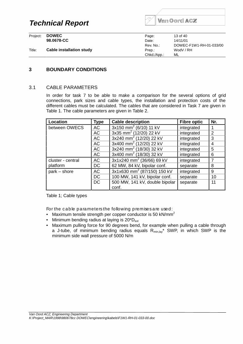
In order for task 7 to be able to make a comparison for the several options of gridconnections, park sizes and cable types, the installation and protection costs of thedifferent cables must be calculated. The cables that are considered in Task 7 are given inTable 1. The cable parameters are given in Table 2.
Location Type Cable description Fibre optic Nr.AC 3x150 mm2 (6/10) 11 kV integrated 1AC 3x35 mm2 (12/20) 22 kV integrated 2AC 3x240 mm2 (12/20) 22 kV integrated 3AC 3x400 mm2 (12/20) 22 kV integrated 4AC 3x240 mm2 (18/30) 32 kV integrated 5
between OWECS
AC 3x400 mm2 (18/30) 32 kV integrated 6AC 3x1x240 mm2 (36/66) 69 kV integrated 7cluster - central
platform DC 62 MW, 84 kV, bipolar conf. separate 8AC 3x1x630 mm2 (87/150) 150 kV integrated 9DC 100 MW, 141 kV, bipolar conf. separate 10
park – shore
DC 500 MW, 141 kV, double bipolarconf.
separate 11
Table 1; Cable types
For the cable parameters the following premises are used:• Maximum tensile strength per copper conductor is 50 kN/mm2
• Minimum bending radius at laying is 20*Dext
• Maximum pulling force for 90 degrees bend, for example when pulling a cable througha J-tube, of minimum bending radius equals Rmin,lay* SWP, in which SWP is theminimum side wall pressure of 5000 N/m

Technical Report
Project: DOWEC Page: 14 of 4098.0678-CC Date: 14/11/01
Rev. No.: DOWEC-F1W1-RH-01-033/00Title: Cable installation study Prep.: WodV / RH
Chkd./App.: ML
Van Oord ACZ, Engineering DepartmentK:\Project_MAR\1998\980678cc DOWEC\engineering\kabels\F1W1-RH-01-033-00.doc
Nr. Dext. Wem Wsubm Fmax Fmax,R Rmin,lay
1 74 mm 11 kg/m 8 kg/m 22.5 kN 7.5 kN 1.5 m2 67 mm 8 kg/m 5 kg/m 5.3 kN 7.5 kN 1.5 m3 95 mm 18 kg/m 13 kg/m 36 kN 10 kN 2.0 m4 106 mm 24 kg/m 17 kg/m 60 kN 12.5 kN 2.5 m5 107 mm 21 kg/m 14 kg/m 36 kN 12.5 kN 2.5 m6 118 mm 27 kg/m 18 kg/m 60 kN 12.5 kN 2.5 m7 140 mm 38 kg/m 26 kg/m 36 kN 15 kN 3.0 m8 2x65 mm +
1x13 mm2*10 kg/m +0.18 kg/m
2*8 kg/m +0.05 kg/m
2*6 kN +9 kN
7.5 kN 1.5m /0.5 m
9 214 mm 85 kg/m 64 kg/m 94.5 kN 22.5 kN 4.5m10 2*96 mm +
13 mm2*24 kg/m +0.18 kg/m
2*18 kg/m +0.05 kg/m
2*31.5 kN + 9 kN
10 kN 2.0m /0.5 m
11 2*96 mm +13 mm
2*24 kg/m +0.18 kg/m
2*18 kg/m +0.05 kg/m
2*31.5 kN + 9 kN
10 kN 2.0m /0.5 m
Dext. = External diameterWem = Emerged weight (approx.)Wsubm = Submerged weight (approx.)Fmax = Maximum pulling force for straight cableFmax,R = Maximum pulling force for 90 degrees bend of minimum bending radiusRmin,lay = Minimum bending radius at laying operation
Table 2; Cable parameters
3.2 EXTREME MET-OCEAN CONDITIONS
Extreme met-ocean conditions for the locations III and VII are supplied by Task 5 ofWorkpackage 1 of the DOWEC study. The extremes are derived from the NESS/NEXTdatabase. In Table 3 the results of Task 5 used for the present study are presented.
The symbols used in this chapter are listed below:Hs Significant wave heightTz Mean zero crossing periodVav. Current velocity averaged over the water depthepos. Positive elevation (storm surge + tide)eneg. Negative elevation (storm surge + tide)

Technical Report
Project: DOWEC Page: 15 of 4098.0678-CC Date: 14/11/01
Rev. No.: DOWEC-F1W1-RH-01-033/00Title: Cable installation study Prep.: WodV / RH
Chkd./App.: ML
Van Oord ACZ, Engineering DepartmentK:\Project_MAR\1998\980678cc DOWEC\engineering\kabels\F1W1-RH-01-033-00.doc
Location III Location VIILongitude of the centre of site 4°25′E 3°30′ELatitude of the centre of site 52°50′N 52°15′NDistance from centre to shore 17 km 50 kmSize Square
10x10 km2Rectangular
20x5 km2
Orientation One side in SSWdirection
Short side in SSWdirection
Closest to shore North of Petten Rotterdam Maasvlakte
Met-ocean conditions with returnperiod of 10 years:
Hs
Tz
Vav.
epos.
eneg.
6.027.200.742.46
-1.45
msm/smm
5.787.100.922.11
-1.07
msm/smm
Met-ocean conditions with returnperiod of 50 years:
Hs
Tz
Vav.
epos.
eneg.
6.837.900.772.72
-1.60
msm/smm
6.357.600.952.39
-1.23
msm/smm
Met-ocean conditions with returnperiod of 100 years:
Hs
Tz
Vav.
epos.
eneg.
7.148.100.792.82
-1.65
msm/smm
6.507.700.962.49
-1.29
msm/smm
Table 3; Extreme met-ocean conditions
3.3 BATHYMETRY
For further design the bathymetry of the area around these two locations must be knownas well. The Dutch part of the North Sea is surveyed on a regular basis by the “Dienst derHydrografie” of the Ministry of Defence, Royal Dutch Navy. Information on the bathymetryin the DOWEC areas was requested by VOACZ.
For the two DOWEC locations a total of three surveys were carried out from which thedata was extracted by the “Dienst der Hydrografie”. The maps did not cover the completeenvisaged DOWEC areas. About 45% of the site area at location III were covered duringtwo surveys at 1993 and 1999. The survey map of 1986 for location VII covered about

Technical Report
Project: DOWEC Page: 16 of 4098.0678-CC Date: 14/11/01
Rev. No.: DOWEC-F1W1-RH-01-033/00Title: Cable installation study Prep.: WodV / RH
Chkd./App.: ML
Van Oord ACZ, Engineering DepartmentK:\Project_MAR\1998\980678cc DOWEC\engineering\kabels\F1W1-RH-01-033-00.doc
65% of the total site area. The maximum and minimum seabed levels at the two locationsare given in Table 4.
Seabed level Location III Location VIIMaximum depth CD - 24.9 m CD - 34.2 mMinimum depth CD - 19.4 m CD - 20.7 m
Table 4; Seabed levels
The tidal range at the two locations is taken from the British Admiralty Chart 1408 (latestupdate: 1988) and is given in Table 5.
Tidal levels Location III Location VIIMLWS CD + 0.2 m CD + 0.2 mMSL CD + 1.0 m CD + 1.0 mMHWS CD + 1.9 m CD + 2.0 m
Table 5; Tidal levels
3.4 SOILS
Soil data from the actual vicinities of the two sites has been supplied by task 5.Information was available mainly from sediment grab samples and cores in the vicinity ofboth locations and seismic profiles in the vicinity of site VII.
The seabed around site III consists of fine to coarse sand with shell fragments, locally siltyor gravelly.
The seabed around site VII consists of Holocene sediments of 5 to 20m thick overlying a 5to 10m thick layer of soils of the Brown Bank Formation. The Holocene sediments aroundsite VII consist of two types of soil: fine to medium sands with mud laminae; fine grainedmuddy sands with interbedded clays. The Brown Bank Formation mainly consists of siltyclays with thin interbeds of shelly gravelly sands. The clay is firm to stiff. Sandwaves areabundant in this area and vary in amplitude from 3 to 8 m.
3.5 STABLE ROCK SIZE FOR SPECIFIED MET-OCEAN CONDITIONS
For the Met-Ocean conditions as given above, the required rock size that remains stableunder the given circumstances is determined using the Bijker-Shields method forcombined steady and oscillatory flow. The calculated rock size is a D50, which is a sievediameter through which 50% of a rock grading can pass. The calculated stable D50’s aregiven in Table 6. A suitable standard rock grading should be chosen for each D50.

Technical Report
Project: DOWEC Page: 17 of 4098.0678-CC Date: 14/11/01
Rev. No.: DOWEC-F1W1-RH-01-033/00Title: Cable installation study Prep.: WodV / RH
Chkd./App.: ML
Van Oord ACZ, Engineering DepartmentK:\Project_MAR\1998\980678cc DOWEC\engineering\kabels\F1W1-RH-01-033-00.doc
Return Period Location III Location VII10 yrs D50 = 227 mm D50 = 233 mm50 yrs D50 = 291 mm D50 = 280 mm100 yrs D50 = 310 mm D50 = 289 mm
Table 6; Stable rock sizes
3.6 HAZARD DESIGN PARAMETERS
The following typical dimensions of hazardous objects are applicable for the protectiondesign of the power cables connecting the turbines as well as the cable connecting thewind park to shore.
3.6.1 FISHING EQUIPMENT DIMENSIONS
To assess the hazard to the cable caused by fishing activities, information from the RIVOhas been obtained. The following ground penetrating equipment is regularly used in thenear shore section of the Dutch Sector:• Beam trawls with a penetration <0.2m• Limited otterboard trawling with boards with a penetration of maximum 0.2m.
3.6.2 DESIGN SHIPS ANCHOR
The area of interest is the near-shore area along the Dutch coast. The shipping use of thissection is limited due to the limited waterdepth. The ultra-large bulk carriers and crude-oilcarriers take a more offshore route.
The area considered is known as the “coastmiddle” section. The information provided showedthat this section is mostly frequented by generalcargo vessels; i.e. coasters. Typical dead weighttonnage of these vessels does not exceed 20000 T.This results in typical ships-anchor weights of5000kg.
The following dimensions can be given tocharacterise such ships-anchors:A: Shank length 2.5mB: Anchor width 1.9mC: Fluke width 0.5mD: Fluke Length 1.8m
D
A
B
C

Technical Report
Project: DOWEC Page: 18 of 4098.0678-CC Date: 14/11/01
Rev. No.: DOWEC-F1W1-RH-01-033/00Title: Cable installation study Prep.: WodV / RH
Chkd./App.: ML
Van Oord ACZ, Engineering DepartmentK:\Project_MAR\1998\980678cc DOWEC\engineering\kabels\F1W1-RH-01-033-00.doc
4 PROTECTION DESIGNS
Based on the above described design parameters, the cable protection requirement canbe determined. The different cable sections are separated into 4 different locationcategories for which the design shall be specified. These location categories are:• Scour Protection Traverse – The section of the connecting cable traversing the scour
protection to be installed around the mono-pile of the wind turbine.• In field sections – the sections of cable interconnecting the wind turbines. These cable
sections are located inside the wind park area and are partially protected by thepresence of the wind turbines.
• Shore connection – The final cable section connecting the wind park to the onshoregrid. This section of the cable traverses open sea where shipping and fishing activity isnot hindered in any way.
• Shore Landing – The section of the cable as it traverses the surf zone, beach anddunes to the connection point to the shore grid. This section is subject to the mostsevere environmental changes and the possible disruption by recreationists.
4.1 BURIAL PROTECTION INDEX
Protection of a cable by means ofburial can be seen as the mostpromising method of protection.The only parameter in the designof the burial protection is the burialdepth. It has always beenrecognised that “stronger” seabedsoils provide a greater protectionthan a “softer” soil for a cableburied to similar depth. In 1997(Mole at al) the Burial ProtectionIndex (BPI) was introduced toaccount for such soilcharacteristics. The chart producedby Mole et al is reproduced here.P. Allen gave a further definition ofthe BPI in 1999. Burial Protection Index
Bur
ial D
epth
[m]
10 2 3
3
2
1
0
Very Soft Clay
Coarse sand Firm Clay
Fine Sand

Technical Report
Project: DOWEC Page: 19 of 4098.0678-CC Date: 14/11/01
Rev. No.: DOWEC-F1W1-RH-01-033/00Title: Cable installation study Prep.: WodV / RH
Chkd./App.: ML
Van Oord ACZ, Engineering DepartmentK:\Project_MAR\1998\980678cc DOWEC\engineering\kabels\F1W1-RH-01-033-00.doc
The following indexing was given:BPI = 1 Depth of Burial consistent with protecting a cable against normal fishing gear
only. Would be appropriate to water depths greater than say 100m whereanchoring of ships is unlikely, or in areas where shipping and anchoring iseffectively prohibited.
BPI = 2 Depth of Burial will provide protection from vessels with anchors up to app. 2tonnes. This may be adequate for normal fishing activities but would not besuitable for larger ships’ anchors.
BPI = 3 Depth of Burial sufficient to protect from anchors of all but the largest ships.Suitable for anchorages and heavily trafficked shipping channels withadjustments made to suit known ship/anchor sizes.
Above basis is proposed to be used in the protection design with necessary adjustmentsfor the local conditions and method of burial and nature of any backfill soil.
4.2 TIE-IN & SCOUR PROTECTION TRAVERSE
4.2.1 HAZARD IDENTIFICATION
The traverse of the scour protection covers that section of the cable from the point of exiton the monopile to the point where burial depth has been reached.
Potential hazards in this area can be defined as:• Fishing activity prohibited – no trawling or other ground penetrating activity• Vessel traverse prohibited – no dragging anchors• Anchoring of work vessels under strict control of anchor position – no threat to cable• Heavy lifting operation due to installation and maintenance expected – dropped
objects possible• Scour protection rock cover creates enhanced turbulence – water-induced tension and
abrasion in case of exposed cable.
4.2.2 SELECTION OF PROTECTION PRINCIPLE
Based on the above hazard identification, adequate protection can be found by assuringthe cable is placed below the scour protection. This can be achieved by installing thescour protection after installation of the cable, or by installing a J-tube extensionimmediately after installation of the foundation pile. The scour protection layer is installedover the J-tube extension. This J-tube extension creates a duct under the scour protectionfor later pull-in of the cable.
The operations of the scour protection installation requires additional care at the positionof the J-tube extension to ensure that filter material covers the J-tube extension beforeplacing the armour material to prevent denting the J-tube, and assuring that no rockcovers or blocks the extension bellmouth.

Technical Report
Project: DOWEC Page: 20 of 4098.0678-CC Date: 14/11/01
Rev. No.: DOWEC-F1W1-RH-01-033/00Title: Cable installation study Prep.: WodV / RH
Chkd./App.: ML
Van Oord ACZ, Engineering DepartmentK:\Project_MAR\1998\980678cc DOWEC\engineering\kabels\F1W1-RH-01-033-00.doc
Once the cable is installed, trenching of the exposed section will take place. However asection of cable will remain exposed from the bell mouth until full burial depth has beenreached. This section needs to be covered to provide the intended protection index. A rockcover will be post-installed to complete the protection. As a first indication app. 250t rockper OWEC is envisaged.
Over time scouring of the seabed at the edge of the rock cover can be expected. Howeveras the detailed loading by waves, currents and induced turbulence on the one side andlocal characteristics of the movable seabed material on the other side are unknown, it isimpossible to accurately predict the extend of scouring that will take place.
When significant erosion holes next to the scour protection develop, it is likely that theedges of the rock cover will gradually sink in these erosion holes. However as a rockblanket is flexible, it will adapt to the changing seabed levels without loosing its protectivecharacteristics. In case the upward slope of the scour hole becomes too steep, rock mightbe transported on to this slope. This will create a so-called falling apron. Depending on thequantity of rock and the extension of the slope covered with rock, the resulting slope anglebecomes more gentle as would be the case with no rock being present.
FOUNDATIONPILE
INTERNALJ-TUBE
MESSENGERWIRE
WINCH &POWERPACK
UNIT
J-TUBEEXTENSION
SCOURPROTECTION
TRANSITION ZONE
J-TUBEEXTENSION
BELLMOUTH

Technical Report
Project: DOWEC Page: 21 of 4098.0678-CC Date: 14/11/01
Rev. No.: DOWEC-F1W1-RH-01-033/00Title: Cable installation study Prep.: WodV / RH
Chkd./App.: ML
Van Oord ACZ, Engineering DepartmentK:\Project_MAR\1998\980678cc DOWEC\engineering\kabels\F1W1-RH-01-033-00.doc
Regular survey of the cable route will be required to verify whether the cable is stillsufficiently covered. In case the survey reveals that scouring progresses exposing thecable, additional stabilisation by means of gravel placement is required. This involves astructured maintenance program and budget.
4.2.3 PROTECTION ALTERNATIVES
The above mentioned cable protection solution is independent of the chosen foundationprinciple. Whether a monopile or tripod is used, scour protection is required to stabilise thefoundation of the OWEC. This scour protection needs to be placed as soon as possibleafter installation of the OWEC foundation. To allow pull-in of the cable after installation ofthe scour protection a J-tube with extension below the scour protection is required.
An alternative protection is to position the cable on top of the scour protection and savethe installation of the J-tube extension. This means that the cable will remain exposed tothe threat of falling objects and the abrasion of the rock surface as the water action rocksand shifts the cable over the scour protection surface. The cable would need to bestrengthened or covered by an additional layer of rock or mattresses to provide protection.In this alternative the transition from the rock surface until full burial depth is reachedremains a problematic area requiring additional cover. The solution is not preferred aslocal strengthening of the cable would require different cable characteristics within onelength, the additionally required rock of different grades would be very expensive and thestability of mattresses is problematic for a turbulent area.
4.3 IN-FIELD SECTION
4.3.1 HAZARD IDENTIFICATION
Between OWECs the following hazards can be identified:• Fishing activity prohibited – no trawling or other ground penetrating activity• Vessel traverse prohibited – no dragging anchors• Anchoring of work vessels under strict control of anchor position – no threat to cable• Heavy lifting operation due to installation and maintenance expected – dropped
objects possible• Sediment movements causing scouring and accretion – possible exposure of cable
4.3.2 SELECTION OF PROTECTION PRINCIPLE
Based on the above hazard identification, a BPI of 1 suffices for the in-field section.According to the BPI chart as presented earlier, this indicates a burial depth of 0.5m in finesandy soils, a burial depth of 1.0m in coarse sandy soils and a burial depth of 2.0 m in softclays. Looking at the seabed soils of the two sites, a burial depth of 1.0 m isrecommended for site III and a burial depth of 0.5 m for site VII.

Technical Report
Project: DOWEC Page: 22 of 4098.0678-CC Date: 14/11/01
Rev. No.: DOWEC-F1W1-RH-01-033/00Title: Cable installation study Prep.: WodV / RH
Chkd./App.: ML
Van Oord ACZ, Engineering DepartmentK:\Project_MAR\1998\980678cc DOWEC\engineering\kabels\F1W1-RH-01-033-00.doc
Stable SeabedAbove burial depths are given as into stable seabeds. If no sandwaves or other dynamicvariations in seabed level are present these burial depths suffice.
Sandwave AreaIn case of sandwaves or similar seabed features, the burial depth needs to be increasedwith the amplitude of the sandwaves to assure sufficient protection. If the amplitudeexceeds the trenchability, at present in the order of 2.5m burial depth for these relativelystiff power cables, pre-sweeping can be chosen. Pre-sweeping involves dredging a trenchthrough the sandwaves until stable seabed level is reached. This needs to be done priorto cable placement. Pre-sweeping needs to be done as close as possible prior to cable-laying and burial. This can pose to be a troublesome operation due to the presence of thepile foundations, requiring careful manoeuvring of the dredge between the piles.
4.3.3 PROTECTION ALTERNATIVES
An alternative consideration, especially for the infield section of the cables, is not to burythe cables into the seabed, but to bury the cables by means of a rock cover. The relativeshort sections between the OWECs make the initiation and finalisation of the trenchingoperations a cumbersome exercise where transition zone rock placement is requiredanyway.
Stable SeabedA rock cover to provide a BPI of 1 can suffice with a cover of 0.5m. This rock bermrequires a rock grading for stability as given in Table 6.
Sandwave AreaIn a sandwave area one can expose the stable seabed level by means of pre-sweeping. Inthat case a required rock cover has similar dimensions and grading as for a stableseabed. Sandwaves will sequentially bury and expose sections of the rock cover withoutexposing the actual cable.
If pre-sweeping is not considered, the rock cover dimensions and grading can be adaptedto allow erosion of sand from under the rock cover. This will result in a gradual lowering ofthe rock cover including the cable as the crest of the sandwave recedes. Once the lowestpoint is reached, accretion will bury the rock berm until some other sandwave trough willre-expose and potentially further erode the sand from under the berm. The volume of rockand initial geometry to be placed has to be considered carefully based on details of thesandwave characteristics to allow the reshaping of the berm without loosing the protectivefunction.
There is no standard solution for a protection design suitable for sandwaves. The costs foreach solution is depending on the situation of the seabed at the moment of installation.Therefore, a design can only be made on a case by case basis.

Technical Report
Project: DOWEC Page: 23 of 4098.0678-CC Date: 14/11/01
Rev. No.: DOWEC-F1W1-RH-01-033/00Title: Cable installation study Prep.: WodV / RH
Chkd./App.: ML
Van Oord ACZ, Engineering DepartmentK:\Project_MAR\1998\980678cc DOWEC\engineering\kabels\F1W1-RH-01-033-00.doc
4.4 SHORE CONNECTION SECTION
4.4.1 HAZARD IDENTIFICATION
The cable section connecting the OWECs and the shoreline covers an open stretch ofseabed. For this section the following hazards can be identified:• Fishing activity – design trawlboard size and other ground penetrating activity• Vessel traffic – coastal shipping route, design anchor to be used• Sediment movements causing scouring and accretion – possible exposure of cable
Considering the amount of traffic traversing any given cable route, and the frequency withwhich skippers drop anchors, the probability of an anchor hitting and damaging a cable isextremely low. The experience around the world however, both with power andcommunication cables, is that a large amount of the cable failures occurring can beascribed to anchor damage. Thus the tendency is to bury the cable to a sufficient depth toavoid any damage due to accidentally dropped and dragged anchor.
4.4.2 SELECTION OF PROTECTION PRINCIPLE
Based on the above hazard identification, the governing hazard is the dropped anddragged ships anchor. The penetration of the given anchor in sandy soils will not exceedmuch more than up to the crown of the anchor. This means with a given fluke length of1.8m that the maximum penetration will be in the order of 1.5m in sandy soils. The burialdepth for the cable in the given soil types, irrespective of fine or coarse soils is set at1.8m. Nevertheless, the need for protection against such anchors should be analysedmore thoroughly on a case by case basis.
Stable SeabedAbove burial depths are given as into stable seabeds. If no sandwaves or other dynamicvariations in seabed level are present these burial depths suffice.
Sandwave AreaIn case of sandwaves or similar seabed features, the burial depth needs to be increasedwith the amplitude of the sandwaves to assure sufficient protection. If the amplitudeexceeds the trenchability, at present in the order of 2.5m burial depth for these relativelystiff power cables, pre-sweeping can be chosen. Pre-sweeping involves dredging a trenchthrough the sandwaves until stable seabed level is reached. This needs to be done priorto cable placement. Once cable is placed normal trenching to intended depth isperformed.
CrossingsWhere foreign facilities as telecom cables, other power cables or pipelines are crossed,protection by trenching is not possible. The cable will be placed on the seabed or on a prelaid gravel bed on both sides at least 30 m from the facility. On these exposed parts rockplacement will be applied. An amount of 500 ton rock is estimated to be sufficient.

Technical Report
Project: DOWEC Page: 24 of 4098.0678-CC Date: 14/11/01
Rev. No.: DOWEC-F1W1-RH-01-033/00Title: Cable installation study Prep.: WodV / RH
Chkd./App.: ML
Van Oord ACZ, Engineering DepartmentK:\Project_MAR\1998\980678cc DOWEC\engineering\kabels\F1W1-RH-01-033-00.doc
4.4.3 PROTECTION ALTERNATIVES
An alternative to burial, i.e. installation of a rock cover, is due to the full length of cable noalternative. Where burial depth is not (fully) reached, for whatever reason, additional coverby means of rock dumping can be considered.
4.5 SHORE LANDING
4.5.1 HAZARD IDENTIFICATION
The shore landing section covers the tidal and surf zones. The offshore boundary istypically the closest position the cable-laying vessel can safely reach. From this pointsupport equipment is needed to pull the offshore cable to shore.
Typical hazards to a cable traversing this section are:• Severe wave and sediment action• Variable seabed profiles and seasonal changes of seabed profile• Recreational activities – digging tourists, garbage cleaning with penetrating equipment.
Especially where receding shorelines are present the protection of the cable has to becarefully considered. The generally applied solution along the Dutch shoreline is to applybeach nourishment. This will be initiated when the shoreline withdrawal is at its maximum,i.e. when the cable protection is at its minimum. At this point in time heavy equipment willstart operation on the beach to facilitate the beach nourishment. Once nourishment isunderway, relatively the burial of the cable will increase, and thus the protection.
To provide sufficient protection for this section of the cable, a BPI of 1 relative to theminimum profile is chosen. This minimum profile depends on the coastal zone morphologyand requires detailed study of the actual location.
4.5.2 SELECTION OF PROTECTION PRINCIPLE
Once the exact location for the shore landing is chosen, historical data on the beachprofiles needs to be collected to establish the minimum profile. From this profile therequired burial depth to provide the BPI of 1 can be established.

Technical Report
Project: DOWEC Page: 25 of 4098.0678-CC Date: 14/11/01
Rev. No.: DOWEC-F1W1-RH-01-033/00Title: Cable installation study Prep.: WodV / RH
Chkd./App.: ML
Van Oord ACZ, Engineering DepartmentK:\Project_MAR\1998\980678cc DOWEC\engineering\kabels\F1W1-RH-01-033-00.doc
4.6 SUMMARY OF PROTECTION DESIGNS
This chapter contains the summary of the findings on protection designs. The standardand optional protection measures against several types of hazards are listed in Table 7.
Hazard Standard protection Optional protectionlocal scour rock cover and surveysand waves burial combined with
pre-sweepingrock cover
dredging route planning anddredging restrictions
fishing burial rock coverdragging anchors burial rock coverdropped objects burial rock cover
Table 7; General protection methods
Protection designs and installation costs are determined for the standard protectionmethods in the different regions of the cable. The protection designs are given in Table 8.
Cable section Protection Designtie-in & scour protectiontraverse
J-tube and rock cover extended J-tube and scourprotection
transition zone from endof scour protection to fullburial
rock cover and survey atregular intervals
250 ton of rock
in-field BPI = 1 at stable seabed site III: 1.0 m burialsite VII: 1.5 m burial pluspre-sweeping
shore connection Deep enough burial against5000 kg ships-anchor belowstable seabed
1.8 m burial
crossings rock cover 500 tonshore landing BPI = 1 relative to minimum
profile1.0 m burial plus exca-vating to minimum level
Table 8; Protection designs

Technical Report
Project: DOWEC Page: 26 of 4098.0678-CC Date: 14/11/01
Rev. No.: DOWEC-F1W1-RH-01-033/00Title: Cable installation study Prep.: WodV / RH
Chkd./App.: ML
Van Oord ACZ, Engineering DepartmentK:\Project_MAR\1998\980678cc DOWEC\engineering\kabels\F1W1-RH-01-033-00.doc
5 INSTALLATION METHODOLOGY
In the following chapters the method of installation will be described as well as theintended equipment to achieve the protection designs. The installation alternatives will bebriefly described as well.
5.1 TIE-IN & SCOUR PROTECTION TRAVERSE
5.1.1 PREPARATION
Prior to installation of the OWEC foundation the foundation system needs to be pre-fabricated including facilities for the pull-in of the cable. These facilities include:• Internal J-tube to allow pull in without exceeding the bending limitations of the cable. –
This can be pre-installed but has to be fabricated to withstand high shock loads duringpile driving, or can be post installed once pile-driving is completed to avoid heavybracing structure. (shock loading up to 1000*g have to be accounted for)
• Connection flange for the external J-tube extension. – Catching device on the outsideof the pile suffices.
• Installation platform on top of monopile, to be installed once pile driving is completed.– This platform includes fixed position points for a pull winch and powerpack.
• Preparation of several winch/powerpack units for the pull in of the cable.
5.1.2 INSTALLATION
The following sequence of actions is envisaged to complete the tie-in of the cable on anOWEC. The sequence is based on the use of a monopile foundation with internal J-tube. Ifa tripod construction is chosen, the details will differ but the sequence of actions remainsthe same.• Installation of the monopile foundation. – installation vessel• Installation of the J-tube extension – support vessel / installation vessel• Placement of scour protection – rock dumping vesselOnce scour protection is completed cable installation can take place, but in principle thiscan be postponed by any length of time to suit scheduling.• If not pre-installed, installation of the internal J-tube and placement of the support
platform in/on top of the pile – support vessel.This action can also be done before the scour protection is placed – installation vessel
• Placement of winch unit on top of foundation pile. Connection of messenger wire in J-tube to winch cable – support vessel
• Clearing and opening of J-tube extension bellmouth and transfer of messenger wireand winch cable to cable laying vessel. – divers from support vessel
• Winch cable connected to cable pull head, cable paid out and simultaneous pullingfrom pull-in winch. – cable-lay vessel
• Once cable full length into OWEC foundation, placement of stopper clamp and fixingof cable to installation platform
Technical Report
Project: DOWEC Page: 27 of 4098.0678-CC Date: 14/11/01
Rev. No.: DOWEC-F1W1-RH-01-033/00Title: Cable installation study Prep.: WodV / RH
Chkd./App.: ML
Van Oord ACZ, Engineering DepartmentK:\Project_MAR\1998\980678cc DOWEC\engineering\kabels\F1W1-RH-01-033-00.doc
• Release of pull-in winch and demobilisation of winch-unit and personnel fromfoundation. – support vessel
• Cable lay and trenching of in-field or shore section. – cable-lay vessel• Rock protection of transition zone from J-tube extension bellmouth until full burial
depth is reached – rock dumping vessel
5.2 IN-FIELD SECTION
5.2.1 PREPARATION
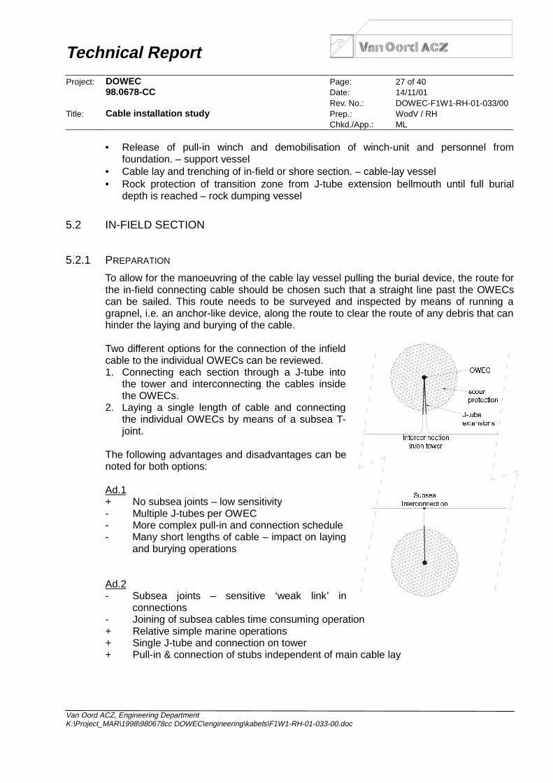
To allow for the manoeuvring of the cable lay vessel pulling the burial device, the route forthe in-field connecting cable should be chosen such that a straight line past the OWECscan be sailed. This route needs to be surveyed and inspected by means of running agrapnel, i.e. an anchor-like device, along the route to clear the route of any debris that canhinder the laying and burying of the cable.
Two different options for the connection of the infieldcable to the individual OWECs can be reviewed.1. Connecting each section through a J-tube into
the tower and interconnecting the cables insidethe OWECs.
2. Laying a single length of cable and connectingthe individual OWECs by means of a subsea T-joint.
The following advantages and disadvantages can benoted for both options:
Ad.1+ No subsea joints – low sensitivity- Multiple J-tubes per OWEC- More complex pull-in and connection schedule- Many short lengths of cable – impact on laying
and burying operations
Ad.2- Subsea joints – sensitive ‘weak link’ in
connections- Joining of subsea cables time consuming operation+ Relative simple marine operations+ Single J-tube and connection on tower+ Pull-in & connection of stubs independent of main cable lay
OWEC
scourprotection
J-tubeextensions
Interconnectionin/on tower
SubseaInterconnection

Technical Report
Project: DOWEC Page: 28 of 4098.0678-CC Date: 14/11/01
Rev. No.: DOWEC-F1W1-RH-01-033/00Title: Cable installation study Prep.: WodV / RH
Chkd./App.: ML
Van Oord ACZ, Engineering DepartmentK:\Project_MAR\1998\980678cc DOWEC\engineering\kabels\F1W1-RH-01-033-00.doc
The actual choice of connection system will depend on the possibilities and final layout ofthe field. For the remainder of this chapter option 1 will be reviewed as that avoids thesubsea connections and consequent weak link in the power transport.
In case of sandwaves present in the area, a suction hopper dredge can be deployed forpre-sweeping of the cable route. Dredged sand can be sidecasted.
5.2.2 INSTALLATION
The following activities need to be considered for the installation of the in-fieldconnections.Cable Laying Vessel:• Load-out of cable lay vessel with cable lengths and preparation of burial tool• Sail to site and take up position at main collection point or OWEC• Pull-in and fixation of cable-head• Lay length of cable to next OWEC – last section with floaters• Connect messenger wire to floating pull-head• Pull-in and fixation of cable tail• Deploy burial tool and bury main length of cable section• Repeat above for all interconnectionsDiving support vessel:• Assist cable laying vessel with pull-in activities• Diver-jetting burial of transition from bellmouth to point where burial tool achieved full
burial depthRock Dumping vessel• Place Rock protection over transition zone
5.3 SHORE CONNECTION SECTION
In general, the cable for the shore connection section will be heavier and stiffer than thecable for the in-field section. Therefore, a larger cable vessel, fitted with a rotating cablepan & sufficient loading capacity, and burial tool are required for the shore connectionsection than for the in-field section, where a smaller vessel will be more cost effective.
5.3.1 PREPARATION
As for the infield cable connections, the cable shall be prepared with pull-heads andreadied for load-out.
In the mean time the route survey and grapnel run, and if necessary pre-sweeping of theroute can be performed.

Technical Report
Project: DOWEC Page: 29 of 4098.0678-CC Date: 14/11/01
Rev. No.: DOWEC-F1W1-RH-01-033/00Title: Cable installation study Prep.: WodV / RH
Chkd./App.: ML
Van Oord ACZ, Engineering DepartmentK:\Project_MAR\1998\980678cc DOWEC\engineering\kabels\F1W1-RH-01-033-00.doc
5.3.2 INSTALLATION
The following activities need to be considered for the installation of the shore connection.Cable Laying Vessel:• Load-out of vessel with cable length and preparation of burial tool• Sail to site and take up position at shore connection point• Pull-in of shore landing section• Deploy burial tool and lay cable and simultaneously bury towards windpark• Take up position for pull-in at central collection point• Pay out rest of the cable with floatation at the cable tail end• Pull in of cable tail at central collection point• Remove floatation and complete burial of remaining cable section
The laying direction can be reversed also, starting at the central collection point andfinishing at the shore end.
5.4 SHORE LANDING
5.4.1 PREPARATION
The shore landing includes the traverse of the beach and hinterland up to the point wherethe connection to the shore grid can be made. For the sake of this document the BeachMan Hole (BMH) is considered the connection point with the shore grid. This man hole islocated at a safe point above the high water mark as close to the beach as possible. Fromthe BMH a duct is drilled to approximately the high water mark on the beach. When theshore connection is installed, the offshore cable is pulled ashore and guided into the duct.A winch installed at the BMH then pulls the offshore cable to the BMH where theconnection to the shore cable is made. The installation of the shore cable to the BMH isnot considered part of the offshore cable installation scope.
5.4.2 INSTALLATION
The following actions complete the shore landing activities:• Cable lay vessel takes up position just offshore of the landing point.• Winch cable is brought from the beach to the cable vessel and connected to cable
pull-head• The cable is paid out, fitted with floaters and pulled onto the beach• The cable gets connected to the messenger wire and transferred into the duct and
pulled to the grid connection manhole.• The floaters are removed from the cable• The burial tool is placed on the cable as close to the beach manhole as possible and
burial of the cable to intended depth commenced• Cable lay vessel continues laying / burying the cable towards the wind park, or to
where the cable has already reached the required depth.

Technical Report
Project: DOWEC Page: 30 of 4098.0678-CC Date: 14/11/01
Rev. No.: DOWEC-F1W1-RH-01-033/00Title: Cable installation study Prep.: WodV / RH
Chkd./App.: ML
Van Oord ACZ, Engineering DepartmentK:\Project_MAR\1998\980678cc DOWEC\engineering\kabels\F1W1-RH-01-033-00.doc
6 INSTALLATION BUDGET PRICES
The budget prices for the total installation can be calculated from the information in thischapter. Variations in distance to shore, number of OWECs and number of parallel powercables to shore can be made.
In paragraph 6.1 the day rates for different pieces of equipment and spreads are given.Typical duration that has to be taken into account for mobilisation and demobilisation isgiven in paragraph 6.2. Multiplying the duration for the mob and demob of the differentspreads with the prices indicated in Table 9, results in the total budget price formobilisation and demobilisation.
With information given in paragraph 6.3 the duration of the cable installation can becalculated for the three different parts, i.e. in field, shore connection and shore landing.The indicated time periods are all for a workability of 100%. These time periods will haveto be multiplied by 1.15 to take into account the efficiency of the performance andmaintenance. Over the resulting time period, the downtime due to waves should be takeninto account. The wave climate is given in Appendix 1 and the operational limit for theseveral actions and ships are given in paragraph 6.3. The required spreads for each partare indicated, so that budget prices for the operational part can be determined bymultiplying the duration for each spread with the prices given in Table 9.
The rates below include fuel, consumables and crew. The purchase of additional rock hasto be taken into account as well. Material costs for the cable, subsea joints, J-tube and on-shore cable infrastructure like the Beach Man Hole are not included.
Situation without scour protectionAn option that was discussed in report DOWEC-F1W1-RH-01-023/01 is not to install ascour protection and allow for the development of a scour hole around the mono pile. Thisalternative will be analysed further by task 11. In order to do so, input is required on thecosts for protection of the cable around the monopile.
One option to achieve the required protection against dropped objects and vibrations is tostrengthen the cable. It should be checked with the cable manufacturers if it can be doneand what the costs will be. In that case additional slack of approximately 15 m should beleft on the seabottom near the monopile in order to avoid spanning of the cable in thescour hole. Also, thought should be given to the way the cable is connected to themonopile, again to avoid a span. A J-tube is less favourable in this case.
Another option is to make a partial scour protection with rock, only over the cable. Anamount of 500 à 1000 ton rock is needed in that case.
Technical Report
Project: DOWEC Page: 31 of 4098.0678-CC Date: 14/11/01
Rev. No.: DOWEC-F1W1-RH-01-033/00Title: Cable installation study Prep.: WodV / RH
Chkd./App.: ML
Van Oord ACZ, Engineering DepartmentK:\Project_MAR\1998\980678cc DOWEC\engineering\kabels\F1W1-RH-01-033-00.doc
6.1 EQUIPMENT
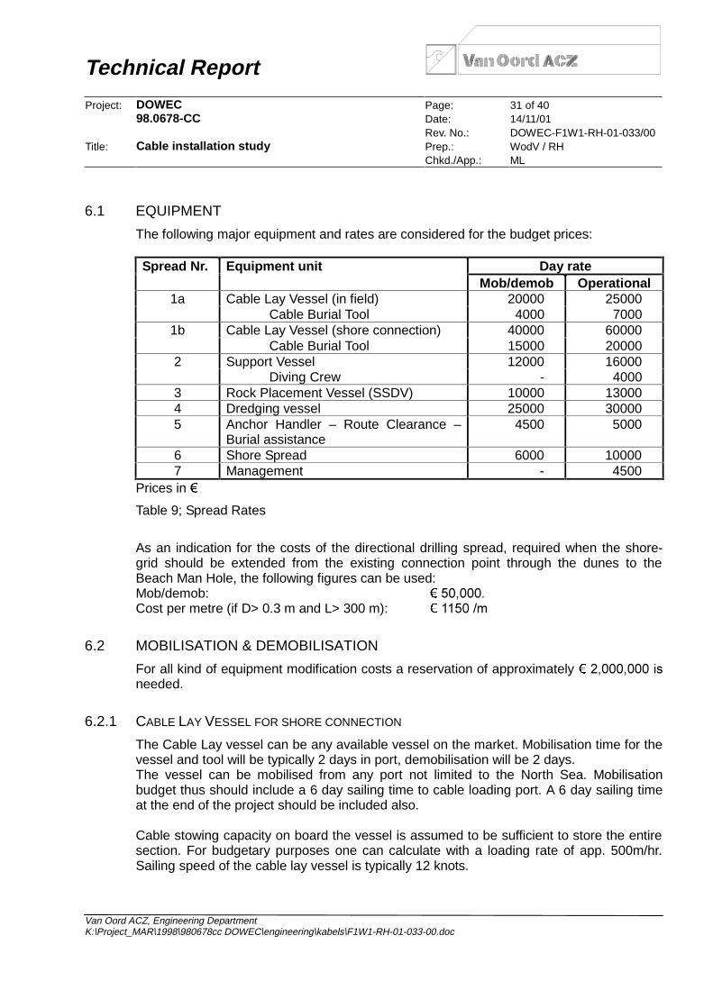
The following major equipment and rates are considered for the budget prices:
Day rateSpread Nr. Equipment unitMob/demob Operational
1a Cable Lay Vessel (in field) 20000 25000Cable Burial Tool 4000 7000
1b Cable Lay Vessel (shore connection) 40000 60000Cable Burial Tool 15000 20000
2 Support Vessel 12000 16000Diving Crew - 4000
3 Rock Placement Vessel (SSDV) 10000 130004 Dredging vessel 25000 300005 Anchor Handler – Route Clearance –
Burial assistance4500 5000
6 Shore Spread 6000 100007 Management - 4500
Prices in
Table 9; Spread Rates
As an indication for the costs of the directional drilling spread, required when the shore-grid should be extended from the existing connection point through the dunes to theBeach Man Hole, the following figures can be used:Mob/demob: ��������Cost per metre (if D> 0.3 m and L> 300 m): �������P
6.2 MOBILISATION & DEMOBILISATION
For all kind of equipment modification costs a reservation of approximately �����������LVneeded.
6.2.1 CABLE LAY VESSEL FOR SHORE CONNECTION
The Cable Lay vessel can be any available vessel on the market. Mobilisation time for thevessel and tool will be typically 2 days in port, demobilisation will be 2 days.The vessel can be mobilised from any port not limited to the North Sea. Mobilisationbudget thus should include a 6 day sailing time to cable loading port. A 6 day sailing timeat the end of the project should be included also.
Cable stowing capacity on board the vessel is assumed to be sufficient to store the entiresection. For budgetary purposes one can calculate with a loading rate of app. 500m/hr.Sailing speed of the cable lay vessel is typically 12 knots.

Technical Report
Project: DOWEC Page: 32 of 4098.0678-CC Date: 14/11/01
Rev. No.: DOWEC-F1W1-RH-01-033/00Title: Cable installation study Prep.: WodV / RH
Chkd./App.: ML
Van Oord ACZ, Engineering DepartmentK:\Project_MAR\1998\980678cc DOWEC\engineering\kabels\F1W1-RH-01-033-00.doc
6.2.2 CABLE LAY VESSEL FOR IN-FIELD SECTION
The vessel for these smaller diameter cables can be mobilised from any port in the NorthSea. Mobilisation budget thus should include a 4 day sailing time to cable loading port. A 4day sailing time at the end of the project should be included also. The on board equipmentrequires adjustment to the cable specifics. The burial tool, typically a jetting devicecapable of handling the relatively stiff cable, will require some adjustment typical of theproject. Mobilisation time for the vessel and tool will be typically 5 days in port,demobilisation will be 3 days.
Cable stowing capacity on board the vessel is 1000 ton. Depending on the actual cablechosen and the distance between the OWECs, several loading sessions have to beundertaken. For budgetary purposes one can calculate with a loading rate of app.500m/hr. Sailing speed of the cable lay vessel is typically 8 knots.
6.2.3 SUPPORT VESSEL
The support vessel is a multi-purpose offshore installation vessel equipped with a cranecapable of various light hoisting operations. The vessel requires adequate deck space forstorage of supplies. The vessel needs to be fitted with a dive support facility and sufficientaccommodation to support a diving crew and if required a jointing team.Mobilisation in port of the vessel requires typically 2 days, demobilisation 1 day.Mobilisation is considered from Rotterdam, thus sailing to and from site 1 day total.
6.2.4 ROCK PLACEMENT VESSEL
A similar rock placement vessel as used for the scour protection installation, i.e. a sidestone dumping vessel (SSDV), can be used. If the planning of the project is suitable, theoperations can be continuous. In that case no extra mobilisation and demobilisation costsneed be included in the cable installation budget.
6.2.5 DREDGING VESSEL
In case the cable route needs to be pre-sweeped, a dredging vessel will be required forthis operation. A TSHD capable of reaching the maximum depth of app. 30m is needed.Day rates are based on a 4500 m3 trailing suction hopper dredger.
The vessel will be mobilised from a North Sea port, resulting in typical mobilisation anddemobilisation time of 4 days.
6.2.6 ROUTE CLEARANCE VESSEL
Route Clearance is executed using an Anchor Handler. Mobilisation includes fitting thevessel with the required survey equipment and other material required for the clearance ofthe route. Mobilisation in port is expected to take 2 days, demobilisation is expected totake 1 day. The vessel shall be mobilised from Rotterdam, sailing time to and from thefield can be taken as 1 day.

Technical Report
Project: DOWEC Page: 33 of 4098.0678-CC Date: 14/11/01
Rev. No.: DOWEC-F1W1-RH-01-033/00Title: Cable installation study Prep.: WodV / RH
Chkd./App.: ML
Van Oord ACZ, Engineering DepartmentK:\Project_MAR\1998\980678cc DOWEC\engineering\kabels\F1W1-RH-01-033-00.doc
6.2.7 SHORE SPREAD
For the shore landing operations, a shore crew with some heavy equipment is required.The equipment needed typically includes a winch for pulling the cable ashore, a bulldozerand a tracked backhoe. The rate given above includes the equipment and personnel.Mobilisation and demobilisation is typically 1 day as it can be locally hired.
6.3 OPERATIONS
6.3.1 ROUTE CLEARANCE
In preparation of the cable laying, the cable route needs to be thoroughly surveyed andcleared of debris. If existing cables are encountered, these have to be identified. If thecable is still in use, the position has to be marked to assure that the burial of the powercable will be suspended for the crossing of the existing cable. If the cable is out of service,a section of the old cable must be removed to allow continuous laying of the new cable.
Normally the route clearance is performed sailing three lines. One over the actual cableroute, and one on each side of the route. However, if the available information on thepresence of the cables is adequate, the adjacent lines can be skipped to be performedonly where necessary, saving a great deal of vessel time.
The survey and route clearance operation can be conducted at a speed of 0.5 knotstypically. The maximum Sea State in which a typical anchor handler can operate is givenby a maximum wave height of 1.5 m.
6.3.2 TIE-INS & IN-FIELD CABLE INSTALLATION
Tie-in operations require the cable lay vessel and the diving support vessel. To assist inthe in-field burial of the cable, a separate support vessel for the operation of the burial toolis required.
Installation of a “stretch” of the in-field cable, including both tie-ins at each end willtypically take 1 day. The maximum sea state in which the cable lay vessel for the in-fieldsection can operate is limited by the tie-in actions and is estimated to be at a maximumsignificant wave height of 1.0 m. Both support vessels will be occupied the same amountof time. Total installation time depends on the actual number of OWECs and consequentlythe number of tie-ins required in the field.
The installation of the transition zone rock protection has to follow suit with the installationof the tie-ins. Thus the total time required for the rock-placement operations is similar asfor the cable installation. The vessel can however be scheduled in combination with thescour protection installation. The required amount of rock for the transition zone isapproximately 250 ton per OWEC at ����WRQ��7KH�UHTXLUHG�DGGLWLRQDO�URFN�GXPSLQJ�WLPHis about 15min per OWEC for the actual installation, and an extra loading session forevery 4 OWECs. Sailing speed of the rock placement vessel is typically 6 knots. Forbudgetary purposes one can calculate with a loading rate of app. 300 ton/hr.

Technical Report
Project: DOWEC Page: 34 of 4098.0678-CC Date: 14/11/01
Rev. No.: DOWEC-F1W1-RH-01-033/00Title: Cable installation study Prep.: WodV / RH
Chkd./App.: ML
Van Oord ACZ, Engineering DepartmentK:\Project_MAR\1998\980678cc DOWEC\engineering\kabels\F1W1-RH-01-033-00.doc
In case pre-sweeping is considered, the dredging operations have to be done as shortlybefore the actual cable laying for each section as possible. Thus, as a first indication onecan consider having the TSHD on site for as long as the cable lay vessel.
6.3.3 SHORE CONNECTION SECTION
Cable laying and simultaneous burial of the cable connecting the wind park to the shorecan be executed at a rate of 300m/hr average. Upon reaching the central collection unit,another ½ day should be taken for the tie-in operation. The operational limit for the cablelay vessel doing the shore connection section is a significant wave height of 1.5m.
6.3.4 SHORE LANDING
The shore landing operations include:• the clearing of the end of the duct, where the directional drill section ends on the
beach,• the pulling of the cable ashore and guiding the cable into the duct,• the handling and positioning of the burial tool over the cable from the beach manhole• the closing of the trench once burial is completed and clearing of the beach site.This has to be repeated for each separate cable that connects the wind park to shore. Ifthe installation can be concluded in one operation, this will save standby time from thecrew and equipment on shore waiting for the return of the cable lay vessel. The entirebeach operations, from commencing work onshore until completed will take no more than2 days. During landing operations, the operational limit for the cable lay vessel will be0.75m significant wave height.

Technical Report
Project: DOWEC Page: 35 of 4098.0678-CC Date: 14/11/01
Rev. No.: DOWEC-F1W1-RH-01-033/00Title: Cable installation study Prep.: WodV / RH
Chkd./App.: ML
Van Oord ACZ, Engineering DepartmentK:\Project_MAR\1998\980678cc DOWEC\engineering\kabels\F1W1-RH-01-033-00.doc
6.3.5 BUDGET TIME SUMMARY
The time frame for the operations can be determined with information from aboveparagraphs. A summary of this information is given in this paragraph.
Cable section Spread Nr. Mob/demob Operational5 4 days
route clearance7 no mob
3 lines over in-field and shoreconnection sections at 0.5 kn
1a 16 days2 4 days4 4 days5 is mobilised7 no mob
1 day per section betweenOWECS including both tie-ins.Plus time required for loading andtransport of the cable for spread 1.in-field operations
3 is mobilised Time required for rock loading,transport and placement of therock in the transition zone.
1b 16 days
7 no mob
Laying speed 300m/hr average.Plus ½ day for a tie-in. Plus timerequired for loading and transportof the cable.shore connection
3 is mobilised Time required for rock loading,transport and placement of therock over the crossings.
1b is mobilised2 is mobilised6 1 day
shore landing
7 no mob
2 days per landing
Table 10; Summary of timeframes
Relevant typical ships properties to determine the required number of loads and theduration of loading and transport of the rock and the cable is given in Table 11.
Vessel Sailing speed Stowing capacity Loading rateCable lay vessel 1a 6 kn 1000 ton 500 m/hrCable lay vessel 1b 12 kn 8000 ton 500 m/hrRock placement vessel 6 kn 1000 ton 150 ton/hr
Table 11; Relevant ships properties

Technical Report
Project: DOWEC Page: 36 of 4098.0678-CC Date: 14/11/01
Rev. No.: DOWEC-F1W1-RH-01-033/00Title: Cable installation study Prep.: WodV / RH
Chkd./App.: ML
Van Oord ACZ, Engineering DepartmentK:\Project_MAR\1998\980678cc DOWEC\engineering\kabels\F1W1-RH-01-033-00.doc
7 EXAMPLE
With the above information budget prices for different park layouts can be calculated. Inthis chapter a typical example of cost calculations for the project is given. Theassumptions for this project are given below.
Assumptions:• Execution period May - August• Location: Site VII (NL 7)• Distance to shore: 60 km• Distances between OWECS: 1,000 m• Number of cables to shore: 1• Number of OWECS: 100• Maximum loading capacity in-field cable vessel: 1,000 ton• Maximum loading capacity shore connection cable vessel: 8,000 ton• Weight of cable to shore: 50 kg/m• Weight of cable between OWECS: 25 kg/m• Rock placement transition zones and crossings subsequently to that of scour
protection, so no extra time required• The cable crosses 3 cables or pipelines• There is no cable platform required between the coast and the collection platform at
the park
Price calculationsRoute clearance: 5) mob/demob = 4 days * ������� � �������5) operations = (60 km+100 OWECS * 1km) * 3 lines per distance / (0.5 knots * 1.852)
= 518 netto hours ⇒ 518 * 1.15 / 88.4% /24 = 28 days * ������� � ��������7) 28 days * ������� � ��������
In-field operations:1a) mob/demob = 16 days * ( ���������� �������� � ��������1a) operations = 100 OWECS * 1 day * 1.15 / 66.5% = 173 days * ( ���������� �������
= ����������2) mob/demob = 4 days * �������� � �������2) operations = 173 days * ( ��������� ��������� � ����������5) operations = 173 days * ������� � ��������7) 173 days * ������� � ��������
Cable loading needs to be done in three parts as maximally 40 km of cable can be stowedin the ship and approximately 100 km is required for the in-field section.• cable loading = {4 * 60 km/(6 knots*1.852) + 100 km/(0.5 km cable loading/hr)} /24 = 9
days * ( ���������� �������� � ��������

Technical Report
Project: DOWEC Page: 37 of 4098.0678-CC Date: 14/11/01
Rev. No.: DOWEC-F1W1-RH-01-033/00Title: Cable installation study Prep.: WodV / RH
Chkd./App.: ML
Van Oord ACZ, Engineering DepartmentK:\Project_MAR\1998\980678cc DOWEC\engineering\kabels\F1W1-RH-01-033-00.doc
The prices involved with the rock required for protection of the cable near the scourprotection and near crossings are given below.• rock material costs transition zone = 100 * 250 ton * ���� � ��������• rock material costs crossings = 3* 500 ton * ���� � �������• rock transport costs = (100 OWECS * 250 ton + 3 crossings* 500 ton) / 1000 ton per
load = 28 trips ⇒ 28 * [2*60 km/(6kn*1.852) + 1000 ton /(300 ton rock loading/hr)] /24 =13 days * ������� � ��������
Shore connection:1b) mob/demob = 16 days * ( ���������� ��������� � ����������1b) operations = (60 km/(0.3 km cable lay/hr) + 12 hours for tie-in at collection platform)
+ (60km/0.5 km cable loading/hr + 60km/(12*1.852) km sailing/hr = 212 netto hoursinstalling + 122 hours sailing and loading ⇒ (212 * 1.15 / 88.4% + 122) / 24 =17 days * ( ���������� ��������� � ����������
2) operations = 212*1.15/88.4% hours = 12 days * ( ���������� �������� � 240,0007) 17 days * ������� � �������
Shore landing:1b) operations = 2 days * 1.15 / 45.9% = 5 days * ( ���������� ��������� � ��������2) operations = 5 days * ( ���������� �������� � ��������6) mob/demob = 1 day * ������� � ������6) operations = 5 days * �������� � �������7) 5 days * ������� � �������
For all kind of equipment modification costs a reservation of approximately ���������� isneeded.
TOTAL BUDGET PRICE: �����������
Additional budget prices for removing sand waves prior to cable installation:4) mob/demob = 4 days * ����000 = ��������4) operations = 173 days * �������� � ����������
Technical Report
Project: DOWEC Page: 38 of 4098.0678-CC Date: 14/11/01
Rev. No.: DOWEC-F1W1-RH-01-033/00Title: Cable installation study Prep.: WodV / RH
Chkd./App.: ML
Van Oord ACZ, Engineering DepartmentK:\Project_MAR\1998\980678cc DOWEC\engineering\kabels\F1W1-RH-01-033-00.doc
REFERENCES
• HY92037 and HY99083, Scale 1:10,000, Depths in metres with respect to MLLWS,WGS84, 1993 and 1999.
• Minuutblad” HY59-LM-3-B, Scale 1:25,000, Depths in decimetres with respect toMLLWS, Hr.Ms. Blommendal, “Dienst der Hydrografie”, Ministry of Defence, RoyalDutch Navy, June 1986.
• “Cable Protection – Solutions through new installation and burial approaches” P.Mole,J. Featherstone, S. Winter, SubOptic 1997 San Fransisco
• “Selecting appropriate cable burial depths”, Peter Allen, Submarine CommunicationsConference, nov. 1999, Cannes
• “Pipeline Risk Analysis”, M. de Jonge, TU Delft, August 1996

Technical Report
Project: DOWEC Page: 39 of 4098.0678-CC Date: 14/11/01
Rev. No.: DOWEC-F1W1-RH-01-033/00Appendix: 1; Wave climates site III and site VII Prep.: WodV / RH
Chkd./App.: ML
Van Oord ACZ, Engineering DepartmentK:\Project_MAR\1998\980678cc DOWEC\engineering\kabels\F1W1-RH-01-033-00.doc
APPENDIX 1
0.0%
10.0%
20.0%
30.0%
40.0%
50.0%
60.0%
70.0%
80.0%
90.0%
100.0%
Occ
urr
ence
(%
)
JAN FEB MAR APR MAY JUN JUL AUG SEP OCT NOV DEC YEAR
Wave climate NL3
< 0.50
< 0.75
< 1.00
< 1.25
< 1.50
< 2.00
< 2.50
<10.00
< 0.50 7.6% 12.1% 9.2% 12.2% 19.5% 22.4% 20.3% 21.6% 11.7% 14.7% 7.1% 10.1% 14.1%
< 0.75 21.0% 31.7% 27.5% 35.6% 47.6% 51.8% 49.2% 47.1% 33.0% 33.1% 24.1% 24.1% 35.5%
< 1.00 36.5% 50.8% 45.0% 57.7% 71.6% 70.0% 70.7% 67.9% 51.6% 48.3% 37.6% 37.9% 53.8%
< 1.25 49.3% 63.6% 57.4% 75.1% 84.2% 83.1% 84.3% 79.8% 66.9% 61.0% 50.6% 49.1% 67.0%
< 1.50 59.5% 71.9% 67.7% 83.9% 91.5% 92.2% 92.1% 85.6% 78.7% 72.9% 60.4% 59.1% 76.3%
< 2.00 75.0% 85.4% 82.8% 93.3% 97.4% 98.8% 97.8% 94.1% 91.3% 87.3% 76.5% 75.0% 87.9%
< 2.50 85.4% 92.1% 92.2% 97.6% 99.8% 99.5% 99.6% 97.8% 96.2% 94.4% 88.6% 85.5% 94.1%
<10.00 100.0% 100.0% 100.0% 100.0% 100.0% 100.0% 100.0% 100.0% 100.0% 100.0% 100.0% 100.0% 100.0%
JAN FEB MAR APR MAY JUN JUL AUG SEP OCT NOV DEC YEAR

Technical Report
Project: DOWEC Page: 40 of 4098.0678-CC Date: 14/11/01
Rev. No.: DOWEC-F1W1-RH-01-033/00Appendix: 1; Wave climates site III and site VII Prep.: WodV / RH
Chkd./App.: ML
Van Oord ACZ, Engineering DepartmentK:\Project_MAR\1998\980678cc DOWEC\engineering\kabels\F1W1-RH-01-033-00.doc
0.0%
10.0%
20.0%
30.0%
40.0%
50.0%
60.0%
70.0%
80.0%
90.0%
100.0%
Occ
urr
ence
(%
)
JAN FEB MAR APR MAY JUN JUL AUG SEP OCT NOV DEC YEAR
Wave climate NL7
< 0.50
< 0.75
< 1.00
< 1.25
< 1.50
< 2.00
< 2.50
<10.00
< 0.50 7.1% 11.1% 10.6% 12.5% 18.6% 21.0% 20.7% 22.0% 13.4% 15.0% 7.9% 9.0% 14.1%
< 0.75 20.3% 31.3% 28.7% 33.6% 43.5% 48.5% 46.5% 45.2% 31.9% 33.6% 24.0% 21.4% 34.1%
< 1.00 35.2% 49.7% 45.0% 55.1% 65.9% 67.8% 68.6% 63.8% 51.2% 46.8% 37.9% 36.0% 51.9%
< 1.25 49.3% 62.6% 58.4% 70.1% 81.3% 81.2% 83.2% 76.3% 68.2% 59.1% 49.3% 47.8% 65.6%
< 1.50 59.5% 70.9% 67.9% 80.4% 89.2% 89.5% 90.5% 84.5% 78.1% 71.0% 59.5% 56.8% 74.8%
< 2.00 74.6% 83.1% 83.6% 91.8% 95.5% 97.9% 96.9% 93.1% 89.9% 84.5% 74.8% 72.5% 86.5%
< 2.50 85.0% 90.9% 92.1% 96.6% 99.3% 99.3% 99.4% 97.8% 95.4% 92.3% 86.6% 84.2% 93.2%
<10.00 100.0% 100.0% 100.0% 100.0% 100.0% 100.0% 100.0% 100.0% 100.0% 100.0% 100.0% 100.0% 100.0%
JAN FEB MAR APR MAY JUN JUL AUG SEP OCT NOV DEC YEAR