
Cable Installation at NSAW Facilities - · PDF fileUNCLASSIFIED//FOR OFFICIAL USE ONLY...
25
UNCLASSIFIED//FOR OFFICIAL USE ONLY UNCLASSIFIED//FOR OFFICIAL USE ONLY (U) Cable Installation at NSA Facilities Version 1.4 Date: 09/25/2008 Derived From: NSA/CSS Manual 1-52 Dated: 08 January 2007 Declassify on: 20320108
Transcript of Cable Installation at NSAW Facilities - · PDF fileUNCLASSIFIED//FOR OFFICIAL USE ONLY...

UNCLASSIFIED//FOR OFFICIAL USE ONLY
UNCLASSIFIED//FOR OFFICIAL USE ONLY
(U) Cable Installation at NSA Facilities
Version 1.4 Date: 09/25/2008
Derived From: NSA/CSS Manual 1-52 Dated: 08 January 2007 Declassify on: 20320108

UNCLASSIFIED//FOR OFFICIAL USE ONLY Document Number: X312-061-1006 Name: Cable Installation at NSAW Facilities
UNCLASSIFIED//FOR OFFICIAL USE ONLY Page 2 of 25
(U) Approval Signature Block
Printed Name Organization Signature Date
John Egolf X312 Patricia Jones X31
Elizabeth Hobbins X32 Carlos Acaron X3 Greg Witschey X3

UNCLASSIFIED//FOR OFFICIAL USE ONLY Document Number: X312-061-1006 Name: Cable Installation at NSAW Facilities
UNCLASSIFIED//FOR OFFICIAL USE ONLY Page 3 of 25
(U) Version Control (U//FOUO) All authorized changes to this document are to be recorded below at the time the changes are received and inserted. This sheet is to be retained in the front of each document, thus enabling ready determination of the configuration status of documents.
Version/Change History
Version # Document Date Description of Change Author (Name)
1.0 12/21/2006 Initial Version Instruction 2-06
Charles Nace X312 Planning & Management
1.1 04/20/07 Updated Format Charles Nace X312 Planning & Management
1.2 3/21/2008 Expanded Grounding and added additional Appendix
Charles Nace, T3212
1.3 9/08/2008 Added para regarding SCIF accreditation
Charles Nace, T3212
1.4 09/25/2008 Added UFC information to Section 2.
Charles Nace, T3212
DOCUMENT OWNER (U//FOUO) Chief, T3212.
DOCUMENT STORAGE (U//FOUO) T3212, Workflow, Standards and Support, maintains this document. Please submit corrections, updates and recommendations to the document owner, for inclusion in future versions. All changes will be approved by T3212 prior to the release of a new version.

UNCLASSIFIED//FOR OFFICIAL USE ONLY Document Number: X312-061-1006 Name: Cable Installation at NSAW Facilities
UNCLASSIFIED//FOR OFFICIAL USE ONLY Page 4 of 25
(U) Table of Contents
1 (U) Introduction ...................................................................................................................... 6 2 (U) Approved Infrastructure and Applications ....................................................................... 6
2.1 (U) Fiber ......................................................................................................................... 7 2.2 (U) Copper ...................................................................................................................... 7
3 (U) Classification Separation.................................................................................................. 8 4 (U) Transport Vehicle ............................................................................................................. 9
4.1 (U) Ground Source........................................................................................................ 11 4.2 (U) Wire-Way Installation Procedures ......................................................................... 11
4.2.1 (U) Securing Sections ........................................................................................... 11 4.2.2 (U) Grounding....................................................................................................... 11 4.2.3 (U) Wire-Way Support ......................................................................................... 11
4.3 (U) Transport Vehicle Identification ............................................................................ 12 4.3.1 (U//FOUO) Wire-Way .......................................................................................... 12 4.3.2 (U) Cabinets and Main Distribution Frames (MDF) ............................................ 12
4.4 (U) Distribution of Services Within an Office.............................................................. 12 4.4.1 (U) Overhead Implementations............................................................................. 12 4.4.2 (U) Station Drop Construction.............................................................................. 12 4.4.3 (U) Station Outlet Patch Cord Connections.......................................................... 13
4.5 (U) Distribution of Services Within a Machine Room................................................. 13 4.5.1 (U) Vertical Wire Management Systems.............................................................. 13 4.5.2 (U) Horizontal Wire Management Systems.......................................................... 13
5 (U) Cable Fabrication ........................................................................................................... 13 6 (U) Cable Administration ..................................................................................................... 16 7 (U) Cable Labeling ............................................................................................................... 16
7.1 (U) Campus Backbone Cabling Identifier .................................................................... 16 7.2 (U) Building Backbone Cabling Identifier ................................................................... 16
7.3 (U) Equipment Room (ER) or Telecommunications Space (TS) Infrastructure Cable Identifier.................................................................................................................................... 17
8 (U) Enclosure Power Panel and Caution Tag ....................................................................... 17 9 (U) Communications Closet Terminations ........................................................................... 18 10 (U) NSTS Instrument Identification ................................................................................. 18 11 (U) Infrastructure Audits................................................................................................... 18 Appendix A (U) Cable Color-Codes and Separation Requirements ........................................... 19 Appendix B (U) Backbone Installation Tracking Database Sample ............................................. 1 Appendix C (U) Label Types......................................................................................................... 1 Appendix D (U) Acronyms............................................................................................................ 2 Appendix E (U) References ........................................................................................................... 3
UNCLASSIFIED//FOR OFFICIAL USE ONLY Document Number: X312-061-1006 Name: Cable Installation at NSAW Facilities
UNCLASSIFIED//FOR OFFICIAL USE ONLY Page 5 of 25
(U) List of Figures Figure 4 (U) Square D NEMA Type 1 Wire Way ........................................................................ 10 Figure 5 (U) TIA/EIA 568B Terminating Instructions................................................................. 15
(U) List of Tables Table 2.2 (U) Approved Cable Applications .................................................................................. 8
UNCLASSIFIED//FOR OFFICIAL USE ONLY Document Number: X312-061-1006 Name: Cable Installation at NSAW Facilities
UNCLASSIFIED//FOR OFFICIAL USE ONLY Page 6 of 25
1 (U) Introduction (U//FOUO) This document provides detailed instructions for the implementation and installation of premise wire infrastructure in support of unclassified and classified networks within NSAW, Build-out Facilities, domestic facilities where NSA controls the plenum1, domestic facilities where NSA does not control the plenum and all OCONUS field sites. This document provides instructions for implementations and installations of premise wiring in communications facilities, office spaces and machine rooms by ITD Internal Service Providers (ISP), External Service providers (ESP), field personnel stationed at the respective facilities or authorized NSA agents.
(U//FOUO) This document applies to all new voice, video, and data cabling including TS/SCI, Secret and Unclassified networks for all NSA facilities identified in the previous paragraph. This includes any construction, restoration, and modernization projects. This document is not intended to justify wholesale replacement and upgrade of existing premise wiring or cable infrastructure unless security violations are found.
(U//FOUO) It is presumed that any facility in which these instructions pertain is protected by approved means of anti-terrorist force protection (ATFP), owned or leased by the NSA/CSS and perimeters monitored by security cameras, intrusion alarms or other means approved and implemented by the Office of Physical Security, Countermeasures/Headquarters Security and Program Protection or Field Security. Where these do not apply, additional Security and TEMPEST counter measures are required. Details are provided in the respective sections of this document.
(U//FOUO) Prior to the installation of any Red communications or network infrastructure, all facilities will have Sensitive Compartmented Information Facility (SCIF) accreditation in accordance with NSA/CSS Manual 130-1, Annex P and NSA/CSS Policy 6-3, Operational Information Systems Security Policy. All installation personnel must be legal U.S. citizens in accordance with NSA/CSS Policy 5-23, Physical Security Requirements for Controlled Areas.
(U//FOUO) Failure to adhere to the Standards outlined in this document will result in delays in activation and possibly denial of services until the facility is certified to be in compliance. Additional site surveys will be conducted by the Office of Technical Security Countermeasures as part of the automated Annex P process detailing appropriate Countermeasures for the respective facility.
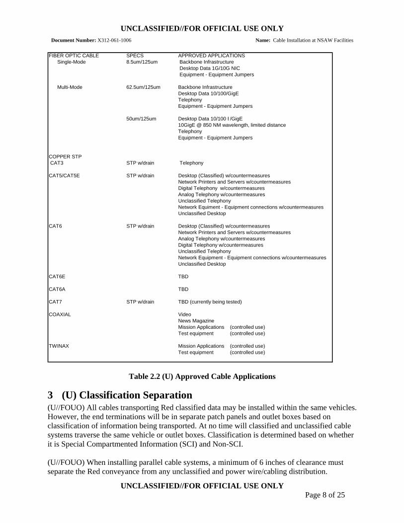
2 (U) Approved Infrastructure and Applications (U//FOUO) Per NSA/CSS Policy 6-18, Secure Network Cabling2, fiber optic cable of total dielectric construction remains the standard methodology for premise wiring implementations. Copper shielded twisted pair (STP) cable is approved where specific applications demand it. At no time will copper unshielded twisted pair (UTP) be permitted for use in transporting classified
1 Controlled plenum is defined as being a space where telecommunications networks infrastructure is installed. Only NSA/CSS personnel or their authorized agents are permitted to install, remove or modify the infrastructure in any way. 2 Policy is effective upon signature of DC31.

UNCLASSIFIED//FOR OFFICIAL USE ONLY Document Number: X312-061-1006 Name: Cable Installation at NSAW Facilities
UNCLASSIFIED//FOR OFFICIAL USE ONLY Page 7 of 25
or unclassified information. All fiber optic and STP cables will meet DOD Unified Facilities Criteria (UFC), Document UFC 3-600-01, Fire Protection Engineering For Facilities. Paragraph 6-8.1.3 Power and Communication Cabling, under Electronic Equipment Installations. "Power and communication (data) cabling installed in spaces above ceilings or below raised floors must be plenum rated or installed in metallic conduit." See Table 2.2.
2.1 (U) Fiber • (U//FOUO) Single-Mode (SM) and Multi-Mode (MM) fiber optic – Telephone, Data,
Video
2.2 (U) Copper • (U) CAT3 STP - w/drain wire – Telephone only
• (U) CAT5/5E STP – Telephone and DATA w/appropriate countermeasures
• (U) CAT6 STP – Telephone and DATA w/appropriate countermeasures
• (U) CAT7 STP – TBD. Waiting for test results and is currently not approved for use
• (U) Coaxial – Video and News Magazine
•
UNCLASSIFIED//FOR OFFICIAL USE ONLY Document Number: X312-061-1006 Name: Cable Installation at NSAW Facilities
UNCLASSIFIED//FOR OFFICIAL USE ONLY Page 8 of 25
FIBER OPTIC CABLE SPECS APPROVED APPLICATIONS Single-Mode 8.5um/125um Backbone Infrastructure Desktop Data 1G/10G NIC
Equipment - Equipment Jumpers
Multi-Mode 62.5um/125um Backbone InfrastructureDesktop Data 10/100/GigETelephonyEquipment - Equipment Jumpers
50um/125um Desktop Data 10/100 E/GigE10GigE @ 850 NM wavelength, limited distanceTelephonyEquipment - Equipment Jumpers
COPPER STP CAT3 STP w/drain Telephony
CAT5/CAT5E STP w/drain Desktop (Classified) w/countermeasuresNetwork Printers and Servers w/countermeasuresDigital Telephony w/countermeasuresAnalog Telephony w/countermeasuresUnclassified TelephonyNetwork Equiment - Equipment connections w/countermeasuresUnclassified Desktop
CAT6 STP w/drain Desktop (Classified) w/countermeasuresNetwork Printers and Servers w/countermeasuresAnalog Telephony w/countermeasuresDigital Telephony w/countermeasuresUnclassified TelephonyNetwork Equipment - Equipment connections w/countermeasuresUnclassified Desktop
CAT6E TBD
CAT6A TBD
CAT7 STP w/drain TBD (currently being tested)
COAXIAL VideoNews MagazineMission Applications (controlled use)Test equipment (controlled use)
TWINAX Mission Applications (controlled use)Test equipment (controlled use)
Table 2.2 (U) Approved Cable Applications
3 (U) Classification Separation (U//FOUO) All cables transporting Red classified data may be installed within the same vehicles. However, the end terminations will be in separate patch panels and outlet boxes based on classification of information being transported. At no time will classified and unclassified cable systems traverse the same vehicle or outlet boxes. Classification is determined based on whether it is Special Compartmented Information (SCI) and Non-SCI.
(U//FOUO) When installing parallel cable systems, a minimum of 6 inches of clearance must separate the Red conveyance from any unclassified and power wire/cabling distribution.

UNCLASSIFIED//FOR OFFICIAL USE ONLY Document Number: X312-061-1006 Name: Cable Installation at NSAW Facilities
UNCLASSIFIED//FOR OFFICIAL USE ONLY Page 9 of 25
Intersections of cable systems must be made at a 90° angle and provide a minimum of two (2) inches vertical separation.
4 (U) Transport Vehicle (U//FOUO) Premise wire cable management systems are strongly recommended for all classified and unclassified services but are not required for raised floor controlled plenum applications. However, when an overhead infrastructure is designed, all classified and unclassified copper and fiber optic communications premise wiring will be installed in a dedicated approved wire management system. Cable management systems mitigate the risk of damage to the critical infrastructure and the possible compromise of sensitive classified data due to improper “after-the-fact” installations.
(U//FOUO) In all other facilities, whether an overhead or under floor infrastructure is designed, all classified and unclassified copper and fiber optic communications premise wiring will be installed in a dedicated approved wire management system.
(U//FOUO) Approved vehicles are Electrical Metallic Tubing (EMT) and anodized or standard painted metallic wire ways (SQUARE-D general purpose NEMA Type-1 w/knockouts in Figure 4) with secured covers, flex and telepoles. Ladder racks with no more than six (6) inches of separation between rungs and cable trays are approved only for installations within telecommunications closets and transport rooms. The designer will scope the size of wire-way to accommodate the total number of cables plus 40% growth.

UNCLASSIFIED//FOR OFFICIAL USE ONLY Document Number: X312-061-1006 Name: Cable Installation at NSAW Facilities
UNCLASSIFIED//FOR OFFICIAL USE ONLY Page 10 of 25
G EN ER A L PUR PO SE – N E M A T Y PE 1 PAINT ED W IR EW AY
1.5 in3.0 in
3.0 in3.0 in
1.5 in
12.00 in5.97 in
12.00 in
Concentric knockout (1-1¼ ) sizes
Concentric knockout (½ -¾ ) sizes
Figure 4 (U) Square D NEMA Type 1 Wire Way

UNCLASSIFIED//FOR OFFICIAL USE ONLY Document Number: X312-061-1006 Name: Cable Installation at NSAW Facilities
UNCLASSIFIED//FOR OFFICIAL USE ONLY Page 11 of 25
4.1 (U) Ground Source (U//FOUO) A dedicated signal ground plate must be provided in each Communications Closet providing NSA services. Approved grounding methods are Signal Reference Ground (SRG) also known as Common Bonding Network (CBN) and Isolated low impedance ground known as Isolated Bonding Network (IBN). The method chosen will be implemented in accordance with TIA/EIA-607-A Commercial Building Grounding and Bonding Requirements for Telecommunications. These grounding networks ultimately terminate to the same Telecommunication Main Ground Bar (TMGB). However, the primary conductors must traverse diverse paths to the TMGB.
(U) (U//FOUO) The SRG/CBN is used as the National Electric Code (NEC)/NFPA70 compliant system for grounding electrical noise generating equipment such as High Volume Air Conditioning (HVAC) systems, transformers and alarm systems. The SRG/CBN provides an independent path to the Telecommunications Main Ground Bar (TMGB). The TMGB is typically installed in a primary electrical switch gear room or service entrance. While NFPA-70 requires a ground of 25 ohms or less, the SRG/CBN when installed in a telecommunications facility provides the same potential to earth ground as the IBN.
(U) Most Original Equipment Manufacturers (OEM) bond the Signal and Safety grounds internal to the devices. However, there are instances where sensitive electronic equipment requires a separate ground source be supplied to an isolated grounding lug. This requires the implementation of an IBN. IEEE-142-1999 requires IBN supporting sensitive electronic equipment to have a measured impedance of 1 ohm or less to the earth ground. The IBN provides a means to properly ground equipment with no risk of stray electrical currents or Radio Frequency Interference (RFI) which may degrade the performance of the associated network, operational missions and in extreme cases damage sensitive electronic equipment.
(U) Approved methods of bonding to the ground plate are cad/exothermic welds and double through bolted using approved grounding connectors, pressure crimps and star lock washers.
4.2 (U) Wire-Way Installation Procedures
4.2.1 (U) Securing Sections (U) Sections of wire-way will be joined using vendor specified unions/straps and secured using machine screws, 2 each outside locking star washers and nut.
4.2.2 (U) Grounding (U) The vehicle will be grounded in accordance with the NFPA-70/National Electric Code (NEC) and TIA/EIA-607-A, Commercial Building Grounding and Bonding Requirements for Telecommunications.
4.2.3 (U) Wire-Way Support (U) Suspend wire-way from building structure using approved methods. The wire-way will be secured to supporting device-using vendor recommended hardware and weight loading specifications.
UNCLASSIFIED//FOR OFFICIAL USE ONLY Document Number: X312-061-1006 Name: Cable Installation at NSAW Facilities
UNCLASSIFIED//FOR OFFICIAL USE ONLY Page 12 of 25
4.3 (U) Transport Vehicle Identification
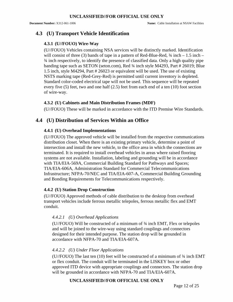
4.3.1 (U//FOUO) Wire-Way (U//FOUO) Vehicles containing NSA services will be distinctly marked. Identification will consist of three (3) bands of tape in a pattern of Red-Blue-Red, ¾ inch – 1.5 inch – ¾ inch respectively, to identify the presence of classified data. Only a high quality pipe banding tape such as SETON (seton.com), Red ¾ inch style M4293, Part # 26019; Blue 1.5 inch, style M4294, Part # 26023 or equivalent will be used. The use of existing NSTS marking tape (Red-Grey-Red) is permitted until current inventory is depleted. Standard color-coded electrical tape will not be used. This sequence will be repeated every five (5) feet, two and one half (2.5) feet from each end of a ten (10) foot section of wire-way.
4.3.2 (U) Cabinets and Main Distribution Frames (MDF) (U//FOUO) These will be marked in accordance with the ITD Premise Wire Standards.
4.4 (U) Distribution of Services Within an Office
4.4.1 (U) Overhead Implementations (U//FOUO) The approved vehicle will be installed from the respective communications distribution closet. When there is an existing primary vehicle, determine a point of intersection and install the new vehicle, to the office area in which the connections are terminated. It is required to install overhead vehicles in areas where raised flooring systems are not available. Installation, labeling and grounding will be in accordance with TIA/EIA-569A, Commercial Building Standard for Pathways and Spaces; TIA/EIA-606A, Administration Standard for Commercial Telecommunications Infrastructure; NFPA-70/NEC and TIA/EIA-607-A, Commercial Building Grounding and Bonding Requirements for Telecommunications respectively.
4.4.2 (U) Station Drop Construction (U//FOUO) Approved methods of cable distribution to the desktop from overhead transport vehicles include ferrous metallic telepoles, ferrous metallic flex and EMT conduit.
4.4.2.1 (U) Overhead Applications (U//FOUO) Will be constructed of a minimum of ¾ inch EMT, Flex or telepoles and will be joined to the wire-way using standard couplings and connectors designed for their intended purpose. The station drop will be grounded in accordance with NFPA-70 and TIA/EIA-607A.
4.4.2.2 (U) Under Floor Applications (U//FOUO) The last ten (10) feet will be constructed of a minimum of ¾ inch EMT or flex conduit. The conduit will be terminated in the LISKEY box or other approved ITD device with appropriate couplings and connectors. The station drop will be grounded in accordance with NFPA-70 and TIA/EIA-607A.

UNCLASSIFIED//FOR OFFICIAL USE ONLY Document Number: X312-061-1006 Name: Cable Installation at NSAW Facilities
UNCLASSIFIED//FOR OFFICIAL USE ONLY Page 13 of 25
(U//FOUO) When installing parallel cable systems, a minimum of 6 inches of clearance must separate the Red conveyance from any unclassified and power wire/cabling distribution. Intersections of cable systems must be made at a 90° angle and provide a minimum of two (2) inches vertical separation.
4.4.3 (U) Station Outlet Patch Cord Connections (U//FOUO) Due to customer requirements for rapid reconfigurations and placement of distribution boxes, it is permissible to extend the desktop access cabling through the flooring system via a protective sleeve.
(U//FOUO) Patch cords connecting premise wiring to desktop device will be no longer than three (3) meters in length, will be STP and terminated with RFI, metallic jacketed connectors and are to be routed so as to maintain a minimum of six (6) inches of separation between power, classified and unclassified services.
4.5 (U) Distribution of Services Within a Machine Room
4.5.1 (U) Vertical Wire Management Systems (U//FOUO) Equipment rack enclosures hosting Local Area Network (LAN) and Wide Area Network (WAN) telecommunications equipment will include vertical wire management systems in the front and rear sections. Approved systems such as the square PANDUIT wire management with covers will be used. The vertical management systems will interface with the horizontal management systems providing a seamless transition and required radius bend for both fiber and copper infrastructures. Installation, labeling and grounding will be in accordance with TIA/EIA-569A, Commercial Building Standard for Pathways and Spaces; TIA/EIA-606A, Administration Standard for Commercial Telecommunications Infrastructure; NFPA70/NEC and TIA/EIA-607A, Commercial Building Grounding and Bonding Requirements for Telecommunications respectively.
4.5.2 (U) Horizontal Wire Management Systems (U//FOUO) Horizontal cable management systems will be installed in all machine rooms and will not be dependent on overhead or under floor implementations. Installation, labeling and grounding will be in accordance with TIA/EIA-569A, Commercial Building Standard for Pathways and Spaces; TIA/EIA-606A, Administration Standard for Commercial Telecommunications Infrastructure; NEC, NFPA70 and TIA/EIA-607A, Commercial Building Grounding and Bonding Requirements for Telecommunications respectively.
5 (U) Cable Fabrication (U//FOUO) All cable will be Plenum rated. When installing CAT5 STP, CAT5E STP or CAT6 STP, it will be terminated with metallic jacketed connectors and in accordance with EIA/TIA-568B (Figure 5). All cables will be contiguous and splice free from Communications closet to the station drop outlet box.

UNCLASSIFIED//FOR OFFICIAL USE ONLY Document Number: X312-061-1006 Name: Cable Installation at NSAW Facilities
UNCLASSIFIED//FOR OFFICIAL USE ONLY Page 14 of 25
(U//FOUO) All copper STP cable jackets will be color-coded respective to the classification of data being transported. Black will denote unclassified data. Purple will denote Red Non-SCI and Red will denote TS/SCI. In the event OEM system cables and/or jumpers are not available in the specified color code, the installer will place a band of ¾ inch industrial grade tape, SETON style M4293, Red (#26019), Black (#26011) or Purple (#26018) or equivalent, three (3) inches from the end of the jacket at the points of origin and destination and at increments of five (5) feet between. All communications cables will be tested for compliance with their intended purposes.
(U//FOUO) Fiber optic jumper jackets will be color coded respective to Single Mode (SM) or Multi Mode (MM). SM will be identified by using a Yellow jacket and Orange will denote MM. The data classification will be identified using colored tape as described in the preceding paragraph.
(U//FOUO) See Appendix C for application and separation criteria relevant to implementations of copper and fiber optic infrastructures.
(U//FOUO) All tests will be documented and made available upon request by ITD personnel or their authorized agents.

UNCLASSIFIED//FOR OFFICIAL USE ONLY Document Number: X312-061-1006 Name: Cable Installation at NSAW Facilities
UNCLASSIFIED//FOR OFFICIAL USE ONLY Page 15 of 25
Step 1. Carefully strip the outer sheath insulation back 1". Roll back the foil shield insulation and wrap the drain wire around the foil. Do not remove and insulation from the conductors.
Step 2. Untwist the pairs to within 1/8" of the jacket. Arrange the wires according to TIA/EIA 568A & 568B standards. Flatten and align the wires. Make one straight cut across all the conductors, removing approximately ½” to ensure the ends are of equal length.
Step 3. Hold the connector in front of you with the locking tab down. Orient the wires so connector Pin 1 aligns with cable Pin 1, etc. Pin 1 is on
the far left. Slide the wires into the CAT5e connector. The cable jacket should extend into the
connector about ¼” for strain relief.
Step 4. Insert the plug into a crimp tool. Firmly squeeze the handles to set the contacts and secure the cable.
Step 5. Test the cable using a cable tester for shorts, opens or miswires.
How to Assemble CAT5e Shielded Solid or Stranded RJ 45 Plugs
1 6 7 85432
GreenPair 3
OrangePair 2
BluePair 1
BrownPair 4
RJ-45 JACKTIA/EIA 568A STANDARD
1 6 7 85432
OrangePair 2
GreenPair 3
BluePair 1
BrownPair 4
RJ-45 JACKTIA/EIA 568B STANDARD
Wiring Diagram
1 6 7 85432
G re e nP a ir 3
O ra n g eP a ir 2
B lu eP a ir 1
B ro w nP a ir 4
R J - 4 5 J A C KT IA / E IA 5 6 8 A S T A N D A R D
1 6 7 85432
O ra n g eP a i r 2
G r e e nP a ir 3
B lu eP a ir 1
B ro w nP a i r 4
R J -4 5 J A C KT IA /E IA 5 6 8 B S T A N D A R D
W ir in g D ia g r a m
Figure 5 (U) TIA/EIA 568B Terminating Instructions

UNCLASSIFIED//FOR OFFICIAL USE ONLY Document Number: X312-061-1006 Name: Cable Installation at NSAW Facilities
UNCLASSIFIED//FOR OFFICIAL USE ONLY Page 16 of 25
6 (U) Cable Administration (U//FOUO) All cables, wire-ways and station drops will be documented in accordance with EIA/TIA-606-A, Administration Standard for Commercial Telecommunications Infrastructure, dated 2002. See Appendix B for data base example.
7 (U) Cable Labeling (U//FOUO) Connections and service loops, at the distribution shelves, will be in accordance with the cable manufacturer’s recommendation and the field site-specific installation requirements. All jumpers3 will be labeled at each end with the minimum of origination/destination information. All cables will be identified with cable markers in accordance with NSA Standard DS-61E. The cable markers will be black printing on a white background. The printing must be legible and not hand-written. All cables will include a unique alphanumeric identifier as described in Sections 7.1, 7.2, and 7.3. Appendix C shows examples of labeling types.
7.1 (U) Campus Backbone Cabling Identifier (U//FOUO) A unique campus backbone cable identifier shall be assigned to each backbone cable connecting Telecommunications Space (TS)4 in different buildings and it shall have the format [b1fs1]/[b2fs2]-n as stated in TIA/EIA-606-A, P20, Section 7.1.2. The format is:
• (U) b1fs1 = building identifier and TS identifier for the TS in which one end of the backbone cable is terminated
• (U) b2fs2 = building identifier and TS identifier for the TS in which the other end of the backbone cable is terminated
• (U) n = one or two alpha-numeric characters identifying a single cable with one end terminated in the TS designated b1fs1 and the other end terminated in the TS designated as b2fs2
(e.g.: R&E TS1 (R1C052) to OPS2A TS1 (Penthouse OP2AP5) Backbone cable 3 = RE-R1C052/OPS2A-OP2AP5-3)
(U//FOUO) All campus backbone cables shall follow the same format and the label shall be placed within 300mm (12 in.) of the end of the cable jacket.
7.2 (U) Building Backbone Cabling Identifier (U//FOUO) A backbone cable between TS in a single building shall have a unique identifier having the format fs1/fs2 – n where:
• (U) fs1 = TS identifier for the space containing the termination of one end of the backbone cable
• (U) fs2 = TS identifier for the space containing the termination of the other end of the backbone cable
3 Jumpers are pre-terminated STP copper or fiber optic cables providing a connection between two telecommunications or network devices. 4 TS is an area used for housing the installation and termination of telecommunications equipment and cable.

UNCLASSIFIED//FOR OFFICIAL USE ONLY Document Number: X312-061-1006 Name: Cable Installation at NSAW Facilities
UNCLASSIFIED//FOR OFFICIAL USE ONLY Page 17 of 25
• (U) n = One or two alphanumeric characters identifying a single cable terminated between fs1 and fs2
(e.g.: OPS2A TS1 (OP2AP5) to OPS2A TS4 (2AB060) cable number 1 = OPS2A-OP2AP5/OPS2A-2AB060 – 1)
(U//FOUO) All building backbone cables shall follow the same format and the label shall be placed within 300mm (12 in.) of the end of the cable jacket.
7.3 (U) Equipment Room (ER) or Telecommunications Space (TS) Infrastructure Cable Identifier
(U//FOUO) A unique cable identifier will be placed on infrastructure cabling connecting a central distribution point to a specified row of equipment racks. The cable identifier will have the format op1/tp1 – n where:
• (U) op1 = The rack location and elevation of copper terminal block or optical fiber Light Guide Exchange (LGX)
• (U) tp1 = The rack location and elevation in which the opposite end of the cable is terminated in the associated copper terminal block or optical fiber LGX
• (U) n = A one or two character numeric designator assigned to the physical cable (e.g.: Distribution rack RBE04 Front Elevation 29 to RBC15 Front Elevation 39 cable number 1 = RBE04-F-29/RBC15-F-39 – 1)
(U//FOUO) ER5 or TS Copper Shielded Twisted Pair (STP) and Optical Fiber Jumper Identifier shall be labeled with a unique identifier having the format op1/tp1 where:
• (U) op1 = The enclosure location and elevation of copper terminal block, optical fiber LGX originating termination, patch panel detail or equipment port
• (U) tp1 = The enclosure location and elevation in which the opposite end of the cable is terminated in the respective copper terminal block, optical fiber LGX originating termination, patch panel detail or equipment port. (e.g.: RBC10 front elevation 35 port 2 to RBC20 rear elevation 40 port 3 = RBC10-F-35 p2/RBC20-R-40 p3)
(U//FOUO) All infrastructure cables shall follow the same format and the label shall be placed within 300mm (12 in.) of the end of the cable jacket.
8 (U) Enclosure Power Panel and Caution Tag (U//FOUO) The rack power panel tag identifies the power disconnect point, including power panel and circuit breaker numbers. The rack power panel tag is required on the front and back of each rack. For those racks equipped with solid doors, the labels will be placed on the inside of each door. Those racks with mesh or vented doors, the labels will be placed on the mounting rails. See Appendix C for example.
5 ER is an enclosed space for housing telecommunications equipment, cable terminations, and cross-connect cabling that is the recognized location of the horizontal cross-connect

UNCLASSIFIED//FOR OFFICIAL USE ONLY Document Number: X312-061-1006 Name: Cable Installation at NSAW Facilities
UNCLASSIFIED//FOR OFFICIAL USE ONLY Page 18 of 25
(U//FOUO) Caution tags are required on the rear of racks containing equipment powered by other than 120 VAC. The caution tag identifies any power usage other than the normal 120 VAC. See Appendix C for example.
(U//FOUO) A unique cable identifier will be placed on cables from rectifiers to the batteries and main distribution panels to the equipment fused distribution panel (BDFP). The label will follow the same format as detailed in Section 5.3 (e.g.: Distribution rack RBE04 Rear Elevation 29 to RBC15 Rear Elevation 39 cable number 1 = RBE04-R-29/RBC15-R-39-1). The tags will be black printing on a yellow background.
9 (U) Communications Closet Terminations (U//FOUO) Approved methods of terminations within the closet are: BIX blocks, LUCENT 110 blocks and KRONE for CAT3 STP Implementation. RJ45/11 patch panels with metallic jacketed female connectors will be used for CAT5 STP, 5E STP and Cat 6 STP.
(U//FOUO) Each equipment rack installed within Red communications closets will be grounded individually to the Red Signal Ground Plate using American Wiring Guide (AWG) #6 stranded or solid core wire.
(U//FOUO) All “wall mounted” cable termination devices will have an “intermediate” ground bus bar and must be installed in close proximity to allow proper termination of cable drain wires. This bus bar will be grounded to the Red Signal Ground Plate using #6AWG stranded or solid core wire.
10 (U) NSTS Instrument Identification (U//FOUO) All telephone instruments connected to the NSTS will be properly labeled with NSA provided “NSTS” stickers. Stickers will be applied to the top of each telephone instrument’s handset.
11 (U) Infrastructure Audits (U//FOUO) The entire distribution system will be inspectable. All cables will be clearly marked and documented in accordance with section seven (7) of this document.

UNCLASSIFIED//FOR OFFICIAL USE ONLY Document Number: X312-061-1006 Name: Cable Installation at NSAW Facilities
UNCLASSIFIED//FOR OFFICIAL USE ONLY Page 19 of 25
Appendix A (U) Cable Color-Codes and Separation Requirements
CABLE APPLICATION COLOR COMMENTS
COPPER 12-900 pr Campus PDS Grey or Black Red and Black transport cables
will be installed in separate conduits and termination frames
12-900 pr Building Vertical Backbone
Grey or Black Must be installed in separate conduits, frames. Physical separation in frame rooms or transport closets. Ex.-Opposite sides of rooms or separate rooms.
12-900 pr Horizontal Transport Grey or Black Must be installed in separate conduits, frames management systems. Physical separation in frame rooms or transport closets. Ex.-Opposite sides of rooms or different rooms.
12-50 pr Inter-machine Connections
Neutral orGrey Color-coded with industrial grade tape. Red=SCI Purple=Non-SCI Black=Unclassified
CAT5E STP InterRow/Rack/ IntraRow/Rack/
Telephony/Desktop
Red Purple Black
SCI Non-SCI Unclassified
CAT6E/A CAT7
TBD TBD
TBD TBD
TBD TBD

UNCLASSIFIED//FOR OFFICIAL USE ONLY Document Number: X312-061-1006 Name: Cable Installation at NSAW Facilities
UNCLASSIFIED//FOR OFFICIAL USE ONLY Page 20 of 25
CABLE APPLICATION COLOR COMMENTS
FIBER
48-144 strands
PDS Black Hybrid cable customer specifies number if SM and MM Red/Black separation using separate conduits and incompatible terminations.
48-144 strands
Vertical Backbone Orange Yellow
MM SM Red/Black separation using separate conduits and incompatible terminations.
12-144 strands
Horizontal Distribution
PDS/Interstate Trans-Oceanic
Orange Yellow
Green
MM SM Red/Black separation using separate conduits and incompatible terminations. TRUEWAVE
1 strand Simplex
InterRow/Rack/ IntraRow/Rack/
Desktop
Yellow w/appropriate color
marking tape
SM Red/Black separation using separate cable management systems and incompatible terminations.
2 strands Duplex
InterRow/Rack/ IntraRow/Rack/
Desktop
Orange w/appropriate color
marking tape
MM Red/Black separation using separate cable management systems and incompatible terminations.

UNCLASSIFIED//FOR OFFICIAL USE ONLY
Appendix B (U) Backbone Installation Tracking Database Sample
STO# STO Name Leg Name Color Status SM Counts MM Counts Truwave Counts Comments
STO 015 MAR Cooper Ave (Bldg 3904) to NBP140 – 144 Fiber
Black Ctd “AY” 1-144 ----- ----- Complete
STO 048 NBP318 NBP140 to NBP318 – 288 Fiber
Red Ctd “EC” 265-552 ----- ----- Complete
STO 064 NBP322 OPS1 to NBP322 Customer Fiber – 288 Fiber
Red Not Started
“RSR” 265-522 ----- ----- Waiting to start NBP322; Crew will terminate
STO 077 FGGM Fiber Upgrade
Fort Meade DCO Fiber Upgrade
Black Hold “DI” 1-36 ----- ----- On hold. Waiting for additional funding
UNCLASSIFIED//FOR OFFICIAL USE ONLY

UNCLASSIFIED//FOR OFFICIAL USE ONLY
UNCLASSIFIED//FOR OFFICIAL USE ONLY
Appendix C (U) Label Types
Type Description Example
Campus Backbone Cables connecting Telecommunications Spaces (TS) in different buildings.
R&E TS1 to OPS2A TS2 Backbone cable 3. RE-R1C052/OPS2A-OP2AP5-3
Building Backbone Cable connecting TS’ in a single building.
OPS2A TS1 to OPS2A TS4 cable 1. OPS2A-OP2AP5/OPS2A-2AB060-1
Equipment Room (ER) or TS Infrastructure
Central distribution point to a specific row of Equipment enclosures.
Distribution rack RBE04 Front Elevation 29 to RBC15 Front Elevation 39 cable 1. RBE04-F-29/RBC15-F-39-1
Equipment-to-Equipment Jumper Cable connecting two (2) pieces of Telecommunications or Networking equipment.
RBC04-R-20 port 4 to RBC07-R-35 port 10. RBC04-R-20 p4/RBC07-R-35 p10
Light Guide Exchange (LGX) or RJ Patch Panel to Telecommunications or Network Equipment Jumper
Optical or Copper Jumper ALL Red copper jumpers must be Shielded Twisted Pair (STP).
LGX or Patch RDC01-F-33 detail 13 to Equipment RDC12-R-14 port 3. RDC01-F-33-13/RDC12-R-14 p3
Power Distribution Connection from Source to Equipment.
48VDC Rectifier RDC10-R-33 connector 5 to Battery Distribution Fuse Board (BDFB) RDC11-R-24 input A. 48VDC RDC10-R-33 p5/ RDC11-R-24 IN A
Enclosure Power Panel and Caution Tag
Identifies power disconnect point (panel and circuit breaker) and Voltage.
120VAC from RDC01 Circuit Breaker 13. 120VAC RDC01-13

UNCLASSIFIED//FOR OFFICIAL USE ONLY Document Number: X312-061-1006 Name: Cable Installation at NSAW Facilities
UNCLASSIFIED//FOR OFFICIAL USE ONLY Page 2 of 25
Appendix D (U) Acronyms
Acronym Definition
ATFP Anti-Terrorist Force Protection AWG American Wire Gauge Standard CAT3 Category 3 – reliably carry data up to 10 Mbits; possible bandwidth of 16
Mbits CAT5 Category 5 – 100MHz CAT5E Category 5 Enhanced – 100MHz CAT6 Category 6 – 250 MHz CAT7 Category 7 – 600 MHz CBN Common Bonding Network EMT Electrical Metallic Tubing IBN Isolated Bonding Network LAN Local Area Network MM Multi mode OEM Original Equipment Manufacturer SM Single mode RF Radio Frequency SRG Signal Reference Ground STP Shielded Twisted Pair TMGB Telecommunications Main Ground Bar UTP Unshielded Twisted Pair WAN Wide Area Network

UNCLASSIFIED//FOR OFFICIAL USE ONLY Document Number: X312-061-1006 Name: Cable Installation at NSAW Facilities
UNCLASSIFIED//FOR OFFICIAL USE ONLY Page 3 of 25
Appendix E (U) References
Reference Number Reference Name
DCID 6-3 Policy Home Page
Protecting Sensitive Compartmented Information Within Information Systems, dated 11 December 2003 http://sitepro.ops.s.nsa/index.cfm?des=djP
X3224 Web ITD Premise Wire Standard (See Jeffrey Parr for hard copy)
LF13 Web LF13 Facility Electrical Engineering Standard (FEES) http://owbsvr-hq-003.eis.nsa/siteclone/62/files/FEES-TOC_Table_of_Content.pdf
Mil-Hndbk-419A Grounding, Bonding and Shielding for Electronic Equipment and Facilities, dated 29 Dec. 1987 ..\..\..\Public\Implementation Standards\milhdbk419a.pdf
NFPA-70 National Electric Code (NEC) http://www.ucao.nsa/enterprise/standards/docs/hardwaredt/NFPA70-2005.pdf
NSA/CSS DS-61E Standards for Preparation of Engineering Documentation, dated 22 Oct. 1999 http://wk-polaroid.j.nsa/da/da02
NSTISSAM 2-95 Red/Black Installation Guidance, dated 03 Feb. 2000 http://www.ucao.nsa/enterprise/standards/docs/hardwaredt/NSTISSAM%202-95%20Amendment.pdf
TELECORDIA GR-326-CORE
Generic Requirements for Single mode Optical Connectors and Jumper Assemblies, dated 03 Sept 1999 http://www.de.nsa/standards/docs/itdt/gr326core.003.pdf
TELCORDIA-409-CORE
Generic Requirements for Premise Fiber Optic Cable, dated 01 May 1994 http://www.de.nsa/standards/docs/itdt/gr409core.001.pdf
TIA/EIA-568-B.1 Commercial Building Telecommunications Cabling Standard, dated 2001 . http://www.de.nsa/standards/docs/itdt/tia_eia-568-b.1.pdf
TIA/EIA-569-B Commercial Building Standard for Telecommunications Pathways And Spaces, dated 1990 http://www.de.nsa/standards/docs/itdt/TIA-569-B%20global_final.pdf
TIA/EIA-606-A Administration Standard for Commercial Telecommunications Infrastructure, dated 2002 http://www.de.nsa/standards/docs/itdt/TIA-EIA-606-A-Final.pdf
TIA/EIA 607-A Commercial Building Grounding (EARTHING) And Bonding Requirements for Telecommunications http://www.de.nsa/standards/docs/itdt/J-STD-607-A-Final.pdf

UNCLASSIFIED//FOR OFFICIAL USE ONLY Document Number: X312-061-1006 Name: Cable Installation at NSAW Facilities
UNCLASSIFIED//FOR OFFICIAL USE ONLY Page 4 of 25
T3212 Public Folder Installation Guidelines, Ford Aerospace And Communications Corp, dated Jan 1986 ..\..\..\Public\Implementation Standards\Installation Guidelines.pdf
UFC 3-600-01 Fire Protection Engineering for Facilities, dated 26 Sept 2006 http://siteworks.nsa/files/827/pdf/fire_protect_UFC_3-600-01.pdf
NSA/CSS 130-1 NSA/CSS Access to NSA/CSS Information Systems and Services, dated 02 April 2004 http://mcdf.afm.usn.nsa/annexp/annexp.pdf
NSA/CSS Policy 6-3 NSA/CSS Operational Information System Security Policy, dated 08 Aug 2006 http://siteworks.nsa/files/199/pdf/Policy_6-3_formatted_25July06.pdf
NSA/CSS Policy 5-23
NSA/CSS Physical Security Requirements for Controlled Spaces Policy, dated 24 Aug 2007 http://siteworks.nsa/files/199/pdf/Policy_5-23.pdf
NSA/CSS Manual 5-23
NSA/CSS Physical Security Requirements for Controlled Spaces Manual, dated 24 Aug 2007 http://siteworks.nsa/files/199/pdf/Manual_5-23.pdf