CABLE, HIGH-FREQUENCY AND CONTROLLED ELECTRICAL 1. …
39
Raychem Wire and Cable 501 Oakside Avenue, Redwood City, CA 94063-3800 NOTE: ANY PRINTED COPY OF THIS DOCUMENT IS AN UNCONTROLLED COPY. SPECIFICATION: 1200 THIS ISSUE: Issue 12 DATE: 20 February 2012 REPLACES: Issue 11 PAGE: 1 of 39 Tyco Electronics Corporation, a TE Connectivity Ltd. Company © 2011-2012 Tyco Electronics Corporation. All rights reserved. CABLE, HIGH-FREQUENCY AND CONTROLLED ELECTRICAL 1. SCOPE This specification covers inspection methods, procedures and requirements for high-frequency and controlled electrical cables. 2. APPLICABLE DOCUMENTS 2.1 GOVERNMENT-FURNISHED DOCUMENTS The following documents, of the issue in effect on the date of invitation for bids or request for proposal, form a part of this specification to the extent specified herein. 2.1.1 Department of Defense SPECIFICATIONS Federal UU-T-450 Tissue, Facial Military MIL-DTL-17 Cables, Radio Frequency, Flexible and Semirigid, General Specification For MIL-DTL-915 Cable, Electrical, for Shipboard Use, General Specification For MIL-DTL-29606 Wire, Electrical, Stranded, Uninsulated Copper, Copper Alloy, or Aluminum, or Thermocouple Extension, General Specification For (Copies of Department of Defense documents may be obtained from the Naval Publications and Forms Center, Standardization Documents Order Desk, Bldg. 4D, 700 Robbins Ave., Philadelphia, PA 19111-5094; or at http://assist.daps.dla.mil/quicksearch/ .)
Transcript of CABLE, HIGH-FREQUENCY AND CONTROLLED ELECTRICAL 1. …

Raychem Wire and Cable 501 Oakside Avenue, Redwood City, CA 94063-3800
NOTE: ANY PRINTED COPY OF THIS DOCUMENT IS AN UNCONTROLLED COPY.
SPECIFICATION: 1200 THIS ISSUE: Issue 12 DATE: 20 February 2012 REPLACES: Issue 11 PAGE: 1 of 39
Tyco Electronics Corporation, a TE Connectivity Ltd. Company © 2011-2012 Tyco Electronics Corporation. All rights reserved.
CABLE, HIGH-FREQUENCY AND CONTROLLED ELECTRICAL
1. SCOPE
This specification covers inspection methods, procedures and requirements for high-frequency and controlled electrical cables.
2. APPLICABLE DOCUMENTS
2.1 GOVERNMENT-FURNISHED DOCUMENTS
The following documents, of the issue in effect on the date of invitation for bids or request for proposal, form a part of this specification to the extent specified herein.
2.1.1 Department of Defense
SPECIFICATIONS
Federal UU-T-450 Tissue, Facial Military MIL-DTL-17 Cables, Radio Frequency, Flexible and Semirigid, General
Specification For MIL-DTL-915 Cable, Electrical, for Shipboard Use, General Specification For MIL-DTL-29606 Wire, Electrical, Stranded, Uninsulated Copper, Copper Alloy, or
Aluminum, or Thermocouple Extension, General Specification For
(Copies of Department of Defense documents may be obtained from the Naval Publications and Forms Center, Standardization Documents Order Desk, Bldg. 4D, 700 Robbins Ave., Philadelphia, PA 19111-5094; or at http://assist.daps.dla.mil/quicksearch/.)

Page 2 of 39 SPECIFICATION 1200, ISSUE 12
NOTE: ANY PRINTED COPY OF THIS DOCUMENT IS AN UNCONTROLLED COPY.
Tyco Electronics Corporation, a TE Connectivity Ltd. Company © 2011-2012 Tyco Electronics Corporation. All rights reserved.
2.1.2 Department of Transportation, Federal Aviation Administration
FEDERAL AVIATION REGULATIONS (FAR) Part 25 Airworthiness Standards: Transport Category Airplanes (Copies of Department of Transportation, Federal Aviation Administration documents may be obtained from the Superintendent of Documents, Government Printing Office, Washington, D.C. 20402; or at www.faa.gov.)
2.2 OTHER PUBLICATIONS
The following documents, of the issue in effect on the date of invitation for bids or request for proposal, form a part of this specification to the extent specified herein.
2.2.1 American Society for Quality (ASQ)
ASQ Z1.4 Sampling Procedures and Tables for Inspection by Attributes (Copies of ASQ documents may be obtained from the American Society for Quality, 600 North Plankinton Avenue, Milwaukee, WI 53203; or at www.asq.org.)
2.2.2 American Society for Testing and Materials (ASTM)
B 193 Standard Test Method for Resistivity of Electrical Conductor Materials D 3032 Standard Test Methods for Hookup Wire Insulation D 4566 Standard Test Methods for Electrical Performance Properties of Insulations
and Jackets for Telecommunications Wire and Cable E 595 Standard Test Method for Total Mass Loss and Collected Volatile
Condensable Materials from Outgassing in a Vacuum Environment (Copies of ASTM documents may be obtained from the American Society for Testing and Materials, 100 Barr Harbor Drive, West Conshohocken, PA 19428-2959; or at www.astm.org.)
2.2.3 Canadian Standards Association (CSA)
C22.2 No. 0.3 Test Methods for Electrical Wires and Cables (Copies of CSA documents may be obtained from the Canadian Standards Association, 5060 Spectrum Way, Suite 100, Mississauga, Ontario, Canada L4W 5N6; or at www.shopcsa.ca.)
2.2.4 International Organization for Standardization (ISO)
8402 Quality Management and Quality Assurance - Vocabulary (Copies of ISO documents may be obtained from the International Organization for Standardization; or at www.iso.org.)

SPECIFICATION 1200, ISSUE 12 Page 3 of 39
NOTE: ANY PRINTED COPY OF THIS DOCUMENT IS AN UNCONTROLLED COPY.
Tyco Electronics Corporation, a TE Connectivity Ltd. Company © 2011-2012 Tyco Electronics Corporation. All rights reserved.
2.2.5 National Electrical Manufacturers Association (NEMA)
WC 27500 Standard for Aerospace and Industrial Electrical Cable (Copies of NEMA documents may be obtained from the National Electrical Manufacturers Association, 1300 North 17th Street, Rosslyn, VA 22209; or at www.nema.org.)
2.2.6 Society of Automotive Engineers (SAE)
AS22759 Wire, Electrical, Fluoropolymer-Insulated, Copper or Copper Alloy AS85485 Cable, Electric, Filter Line, Radio Frequency Absorptive J1128 Low Voltage Primary Cable (Copies of SAE documents may be obtained from the Society of Automotive Engineers, 400 Commonwealth Drive, Warrendale, PA 15096-0001; or at www.sae.org.)
2.2.7 Underwriters Laboratories (UL)
UL 1581 Reference Standard for Electrical Wires, Cables and Flexible Cords (Copies of UL documents may be obtained from Underwriters Laboratories Inc., 1655 Scott Boulevard, Santa Clara, CA 95050-4169; or at www.ul.com.)
3. REQUIREMENTS
3.1 SPECIFICATION SHEETS
3.1.1 Requirements
The requirements for the cables furnished under this specification shall be as specified herein and in accordance with the applicable specification sheet. In the event of a conflict, the requirements of the specification sheet shall govern.
3.1.2 Temperature Rating
The temperature rating, when shown on the specification sheet, is based on data obtained from either testing of the insulation material(s) using the mechanical and electrical integrity of the product as defined by ASTM D 3032, Section 14, as the basis for the rating, or by industry-defined standards for the type of material. The temperature rating is not based on possible changes to the electrical characteristics of the cable which might occur as a result of exposure to temperature extremes.
3.2 MATERIALS
Materials not specifically designated herein shall be of the quality and form best suited for the purpose intended. Unless otherwise specified, the materials shall meet the following requirements:

Page 4 of 39 SPECIFICATION 1200, ISSUE 12
NOTE: ANY PRINTED COPY OF THIS DOCUMENT IS AN UNCONTROLLED COPY.
Tyco Electronics Corporation, a TE Connectivity Ltd. Company © 2011-2012 Tyco Electronics Corporation. All rights reserved.
3.2.1 Conductor Materials
Conductor materials shall be in accordance with MIL-DTL-29606 and the applicable specification sheet.
3.2.2 Shield Materials
Shield materials shall be in accordance with NEMA WC 27500 and the applicable specification sheet.
3.2.3 Insulating and Jacket Materials
Insulating and jacketing materials shall be in accordance with the applicable specification sheet.
3.3 CONSTRUCTION
Construction of the finished cable shall be as specified herein and in the applicable specification sheet.
3.3.1 Conductor
Unless otherwise specified in the applicable specification sheet, the conductor construction shall be in accordance with MIL-DTL-29606.
3.3.1.1 Conductor Elongation and Breaking Strength
Prior to dielectric extrusion, elongation and tensile strength of the conductor shall be in accordance with MIL-DTL-29606, as applicable. Other materials not covered by MIL-DTL-29606 shall be in accordance with the applicable specification sheet.
3.3.2 Shield
The shield shall be constructed so as to meet all physical and surface transfer impedance requirements of the applicable specification sheet. The shield shall be free of irregularities, discontinuities, and whole braid splices.
3.3.3 Insulation and Jackets
All insulating and jacket materials shall be constructed as specified in the applicable specification sheet.
3.3.4 Wraps
Tape wraps, when required, shall be applied with an overlap of 25 percent, minimum, unless otherwise specified in the applicable specification sheet. Tape overlap shall be determined in accordance with 4.5.33.

SPECIFICATION 1200, ISSUE 12 Page 5 of 39
NOTE: ANY PRINTED COPY OF THIS DOCUMENT IS AN UNCONTROLLED COPY.
Tyco Electronics Corporation, a TE Connectivity Ltd. Company © 2011-2012 Tyco Electronics Corporation. All rights reserved.
3.4 DETAIL REQUIREMENTS
Finished cable shall conform to the requirements of Table 1 and to those of the applicable specification sheet.
3.4.1 Cabling
The required number of components as specified in the applicable specification sheet shall be cabled together with a left-hand lay. The lay length of the components, when required, shall be as specified in the applicable specification sheet.
3.4.2 Conductor and Shield Continuity
Prior to shipment, one hundred percent of all finished cable shall be tested for continuity. There shall be no indication of discontinuity in any of the component wires or shields, as applicable.
3.4.3 Dielectric Concentricity
Where required, the dielectric concentricity shall be in accordance with the applicable specification sheet when tested in accordance with 4.5.9.
3.4.4 Flammability
Finished cable shall be tested in accordance with 4.5.14 to the appropriate method as specified in the applicable specification sheet. Unless otherwise specified, finished cable shall meet the following requirements:
3.4.4.1 Method A, Vertical Test, Inclined Burner
60 seconds (maximum) 25 percent (maximum) of flag burned No flaming of cotton
3.4.4.2 Method B, 60° Test, Inclined Burner
30 seconds (maximum) 3 inches (76 mm) (maximum) No flaming of facial tissue
3.4.4.3 Method C, Horizontal Test, Vertical Burner
No flaming of indicator papers.
3.4.4.4 Method D, 45° Test, Inclined Burner
70 seconds (maximum)

Page 6 of 39 SPECIFICATION 1200, ISSUE 12
NOTE: ANY PRINTED COPY OF THIS DOCUMENT IS AN UNCONTROLLED COPY.
Tyco Electronics Corporation, a TE Connectivity Ltd. Company © 2011-2012 Tyco Electronics Corporation. All rights reserved.
3.4.5 Jacket Concentricity and Wall Thickness
Unless otherwise specified in the applicable specification sheet, the jacket concentricity shall be 70 percent, minimum, when tested in accordance with 4.5.17. The jacket wall thickness shall be as specified in the applicable specification sheet.
3.4.6 Jacket Flaws
One hundred percent of finished shielded and jacketed cable shall pass the impulse test or the spark test specified in 4.5.18 using the voltage specified in the applicable specification sheet. Testing shall be performed during the final winding of the cable on shipment spools or reels.
3.4.7 Low Temperature-Cold Bend
When finished cable is tested in accordance with 4.5.19, there shall be no cracking and no breakdown of the jacket.
3.4.8 Weight Loss
When required by the specification sheet and tested in accordance with 4.5.32, specimens of cable with woven or spiral, round or flat, shielding shall not exceed the weight loss specified.
3.4.9 Workmanship
All details of workmanship shall be in accordance with high grade wire and cable manufacturing practices. The dielectric and jacket shall be free of cracks, splits, irregularities, and imbedded foreign material.
4. QUALITY ASSURANCE PROVISIONS
4.1 RESPONSIBILITY FOR INSPECTION
The supplier is responsible for the performance of all the inspection tests specified herein. The supplier may utilize his own or any other inspection facility and services acceptable to the buyer. Inspection records of the examinations and tests shall be kept complete and available to the buyer as required.
4.2 INSPECTION CLASSIFICATION
a. Vendor Control (V): Requirements for raw materials such as conductor and insulation materials over which the vendor has control and responsibility.
b. Process Control (P): Inspections performed on samples taken from the lots of cable.
Inspections may be performed on finished cable or after the process which establishes the specified characteristic. The Quality Control Plan establishes the frequency of inspection based on process control data.
c. One Hundred Percent (100%): Tests performed on the total length of each cable. Tests
may be performed on the finished product or "in process", as applicable.

SPECIFICATION 1200, ISSUE 12 Page 7 of 39
NOTE: ANY PRINTED COPY OF THIS DOCUMENT IS AN UNCONTROLLED COPY.
Tyco Electronics Corporation, a TE Connectivity Ltd. Company © 2011-2012 Tyco Electronics Corporation. All rights reserved.
4.3 INSPECTION CONDITIONS
Unless otherwise specified herein, all test inspection conditions shall be in accordance with the following: a. Temperature: 25 ± 10°C b. Relative humidity: 60 ± 15 percent c. Atmospheric pressure: 725 ± 76 mm of mercury
4.4 QUALITY CONFORMANCE INSPECTION
Quality conformance inspection consists of a series of tests and inspections that assure that raw materials and manufacturing processes are consistent and result in products that conform to specification requirements. Quality conformance tests and inspections are listed in Table 1, designated as "P", "V", or "100%", and shall be performed on every lot of cable procured under this specification.
4.4.1 Inspection Definitions
ISO 8402 shall apply for definitions of inspection terms used herein. For purposes of this specification, the following shall apply:
4.4.1.1 Lot
The inspection lot shall include all cable of one part number subjected to inspection at one time.
4.4.2 Nonconforming Inspection Lots
Disposition of inspection lots found unacceptable under initial quality conformance inspection shall be in accordance with ASQ Z1.4.

Page 8 of 39 SPECIFICATION 1200, ISSUE 12
NOTE: ANY PRINTED COPY OF THIS DOCUMENT IS AN UNCONTROLLED COPY.
Tyco Electronics Corporation, a TE Connectivity Ltd. Company © 2011-2012 Tyco Electronics Corporation. All rights reserved.
TABLE 1. PROPERTIES OF FINISHED CABLE
Examination or Test Requirement Test Method *InspectionClass
Adhesion of Conductor Specification Sheet 4.5.1 P Attenuation Specification Sheet 4.5.2 P Blocking Specification Sheet 4.5.3 P Cabling Specification Sheet and 3.4.1 4.5.13 P Capacitance Specification Sheet 4.5.4 P Capacitance Unbalance Specification Sheet 4.5.5 P Characteristic Impedance Specification Sheet 4.5.6 P Color Specification Sheet 4.5.13 P Conductor Elongation and Breaking Strength 3.3.1.1 MIL-DTL-29606 V Conductor and Shield Continuity 3.4.2 4.5.7 100% Conductor and Shield Resistance Specification Sheet 4.5.8 P Conductor Splices MIL-DTL-29606 4.5.13 V Construction and Materials Specification Sheet, 3.2 and 3.3 4.5.13 P Dielectric Concentricity 3.4.3 4.5.9 P Dielectric/Jacket Elongation and Tensile Strength Specification Sheet 4.5.10 P Dimensional Stability Specification Sheet 4.5.11 P Dimensions Specification Sheet 4.5.12 P Flammability Specification Sheet and 3.4.4 4.5.14 P Heat Shock Specification Sheet 4.5.15 P Insulation Resistance Specification Sheet 4.5.16 P Jacket Concentricity and Wall Thickness Specification Sheet and 3.4.5 4.5.17 P Jacket Flaws Specification Sheet and 3.4.6 4.5.18 100% Low Temperature-Cold Bend Specification Sheet and 3.4.7 4.5.19 P Partial Discharge (Corona) Specification Sheet 4.5.20 P Propagation Delay Specification Sheet 4.5.21 P Radiation Resistance Specification Sheet 4.5.22 1/ Shield Coverage Specification Sheet 4.5.23 P Skew Specification Sheet 4.5.24 P Structural Return Loss Specification Sheet 4.5.25 P Surface Transfer Impedance Specification Sheet 4.5.26 P Time Delay Specification Sheet 4.5.27 P Vacuum Stability Specification Sheet 4.5.28 1/ Velocity of Propagation Specification Sheet 4.5.29 P Voltage Withstand (Dielectric) Specification Sheet 4.5.30 100% Weight Specification Sheet 4.5.31 P Weight Loss Specification Sheet and 3.4.8 4.5.32 P Workmanship 3.4.9 4.5.13 P Wraps Specification Sheet and 3.3.4 4.5.33 P
*Inspection Class (see 4.2): P = Process Control 100% = 100% Finished Product Test V = Vendor Test 1/ = Radiation Resistance and Vacuum Stability testing shall be performed at a frequency that has
been agreed upon between the customer and Tyco Electronics.
SPECIFICATION 1200, ISSUE 12 Page 9 of 39
NOTE: ANY PRINTED COPY OF THIS DOCUMENT IS AN UNCONTROLLED COPY.
Tyco Electronics Corporation, a TE Connectivity Ltd. Company © 2011-2012 Tyco Electronics Corporation. All rights reserved.
4.5 TEST METHODS
4.5.1 Adhesion of Conductor
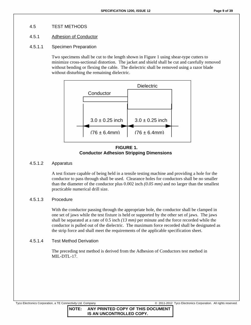
4.5.1.1 Specimen Preparation
Two specimens shall be cut to the length shown in Figure 1 using shear-type cutters to minimize cross-sectional distortion. The jacket and shield shall be cut and carefully removed without bending or flexing the cable. The dielectric shall be removed using a razor blade without disturbing the remaining dielectric.
ConductorDielectric
3.0 ± 0.25 inch
(76 ± 6.4mm)
3.0 ± 0.25 inch
(76 ± 6.4mm)
FIGURE 1. Conductor Adhesion Stripping Dimensions
4.5.1.2 Apparatus
A test fixture capable of being held in a tensile testing machine and providing a hole for the conductor to pass through shall be used. Clearance holes for conductors shall be no smaller than the diameter of the conductor plus 0.002 inch (0.05 mm) and no larger than the smallest practicable numerical drill size.
4.5.1.3 Procedure
With the conductor passing through the appropriate hole, the conductor shall be clamped in one set of jaws while the test fixture is held or supported by the other set of jaws. The jaws shall be separated at a rate of 0.5 inch (13 mm) per minute and the force recorded while the conductor is pulled out of the dielectric. The maximum force recorded shall be designated as the strip force and shall meet the requirements of the applicable specification sheet.
4.5.1.4 Test Method Derivation
The preceding test method is derived from the Adhesion of Conductors test method in MIL-DTL-17.

Page 10 of 39 SPECIFICATION 1200, ISSUE 12
NOTE: ANY PRINTED COPY OF THIS DOCUMENT IS AN UNCONTROLLED COPY.
Tyco Electronics Corporation, a TE Connectivity Ltd. Company © 2011-2012 Tyco Electronics Corporation. All rights reserved.
4.5.2 Attenuation
4.5.2.1 Specimen
The specimen shall be of sufficient length to exhibit at least 3 dB of attenuation at the lowest frequency required. The specimen shall be short enough to ensure that the measured signal is at least 10 dB higher than the measuring system noise floor. If the frequency range is such that one specimen cannot fulfill this requirement, then an additional specimen of suitable length shall be used. For coaxial-type cables, suitable connectors shall be attached to both ends of the cable. For twisted pairs, a connector board with insulation displacement connectors may be used.
4.5.2.2 Procedure
An appropriate test set shall be used to measure the attenuation of the sample. Calibration and specimen measurements shall be made in accordance with the analyzer or system procedures. The attenuation at any frequency shall be determined from the following formula:
Measured Attenuation (dB)x100 Attenuation in dB/100 feet (or dB/100 m) = Specimen length in feet (or meters)
4.5.2.3 Determination of Compliance
Within the frequency range(s) specified in the applicable specification sheet, the attenuation shall not exceed the specified value. Due to reflections, it may be necessary to perform a standard regression analysis on the raw data. The regression polynomial used shall be:
A f a f a f( ) = +1 2 Where: f = Frequency in MHz a1, a2 = Coefficients determined by regression analysis A(f) = Attenuation in dB/100 feet (or dB/100 m) at frequency (f)
The regression analysis is used to smooth out SWR effects. To determine compliance, the frequency (or frequencies) listed on the specification sheet shall be substituted into the above equation, along with the regression coefficients a1 and a2, and the attenuation A(f) calculated.
4.5.2.4 Test Method Derivation
The preceding test method is derived from the Attenuation test methods in MIL-DTL-17 and ASTM D 4566.
4.5.3 Blocking
One end of a continuous length of finished cable shall be affixed to a metal mandrel as specified in the applicable specification sheet. The cable shall then be spirally wound around the mandrel so at least three turns are in close contact with one another. The winding shall be continued until there are three layers of turns with each layer in close contact with one

SPECIFICATION 1200, ISSUE 12 Page 11 of 39
NOTE: ANY PRINTED COPY OF THIS DOCUMENT IS AN UNCONTROLLED COPY.
Tyco Electronics Corporation, a TE Connectivity Ltd. Company © 2011-2012 Tyco Electronics Corporation. All rights reserved.
another. The mandrel and cable shall then be placed within an air oven for the time and at the temperature specified in the applicable specification sheet. After removal from the oven, the mandrel and cable shall be cooled to room temperature and the cable shall be unwound. There shall be no adhesion or sticking of adjacent turns or layers during the unwinding process.
4.5.3.1 Test Method Derivation
The preceding test method is derived from the Blocking test method in NEMA WC 27500.
4.5.4 Capacitance
4.5.4.1 Configuration
For coaxial and triaxial cables only, capacitance shall be measured with a capacitance bridge at 1 kHz, unless otherwise specified in the applicable specification sheet. For pair and triad cables, the frequency shall be 1 MHz, unless otherwise specified. If the frequency specified for shielded or unshielded pairs or triads is 1 kHz, an appropriate capacitance bridge that performs measurements in accordance with ASTM D 4566 may be used.
4.5.4.2 Specimen Preparation
For measuring a frequency of 1 MHz, the specimen shall consist of an approximate 10-foot (3-m) length of finished cable with all shields removed for a distance of 1 inch (25 mm) from each end and the insulation removed for a distance of 0.5 inch (13 mm) from the end of all conductors. The length of the specimen shall be the shielded length. For measuring frequencies other than 1 MHz, the sample shall be prepared as above except that the specimen length shall be less than 1/40 wavelength.
4.5.4.3 Procedure
4.5.4.3.1 Coaxial Cables
The capacitance (C) shall be measured between the inner conductor and outer conductor (shield) with the outer shield grounded.
4.5.4.3.2 Shielded Pair Cables
The capacitance between the two inner conductors shall be measured by the two-terminal method. With the outer conductor (shield) connected to the ground terminal of the capacitance bridge, the mutual capacitance shall be determined as follows: Designate: Ca = Capacitance between no. 1 conductor and no. 2 conductor, with no. 2 conductor
connected to the outer conductor. Cb = Capacitance between no. 2 conductor and no. 1 conductor, with no. 1 conductor
connected to the outer conductor. Cc = Capacitance between no. 1 and no. 2 conductors connected together and the outer
conductor.

Page 12 of 39 SPECIFICATION 1200, ISSUE 12
NOTE: ANY PRINTED COPY OF THIS DOCUMENT IS AN UNCONTROLLED COPY.
Tyco Electronics Corporation, a TE Connectivity Ltd. Company © 2011-2012 Tyco Electronics Corporation. All rights reserved.
The mutual capacitance (Cm) per unit length for each shielded pair shall be determined from the following formula:
C C C Cm
a b c=+ −2
4( )
(Length of specimen)
4.5.4.3.3 Shielded Triad Cables
The capacitance shall be measured by the two-terminal method. With the outer conductor (shield) connected to the ground terminal of the capacitance bridge, the mutual capacitance shall be determined as follows: Designate: Ca = Capacitance between no. 1 conductor and all other conductors connected to the outer
conductor. Cb = Capacitance between no. 2 conductor and all other conductors connected to the outer
conductor. Cc = Capacitance between no. 3 and all other conductors connected together and the outer
conductor. Cd = Capacitance between no. 1, no. 2, and no. 3 conductors connected together and the outer
conductor. The mutual capacitance (Cm) per unit length for each shielded triad shall be determined from the following formula:
( )( )
CC C C C
ma b c d=
+ + −312 Length of specimen
4.5.4.3.4 Unshielded Pair Cables
For unshielded pairs, the procedure shall be the same as given for shielded pair cables except that the overall shield, if any, and all the conductors of the specimen, except the pair under test, shall be connected together and treated as the outer conductor when making measurements. The mutual capacitance (Cm) for each pair shall be determined by the formula specified for the shielded pairs.
4.5.4.3.5 Unshielded Triad Cables
For unshielded triad cables, the procedure shall be the same as given for shielded triads except that the overall shield, if any, and all conductors of the specimen, except those of the triad under test, shall be connected together and treated as the outer conductor when making measurements. The mutual capacitance (Cm) for each triad shall be determined by the formula specified for shielded triads.

SPECIFICATION 1200, ISSUE 12 Page 13 of 39
NOTE: ANY PRINTED COPY OF THIS DOCUMENT IS AN UNCONTROLLED COPY.
Tyco Electronics Corporation, a TE Connectivity Ltd. Company © 2011-2012 Tyco Electronics Corporation. All rights reserved.
4.5.4.4 Test Method Derivation
The preceding test methods are derived from the Capacitance test methods in MIL-DTL-17, MIL-DTL-915, and ASTM D 4566.
4.5.5 Capacitance Unbalance
4.5.5.1 Capacitance Unbalance to Shield
4.5.5.1.1 Capacitance Unbalance Pair-to-Shield
The capacitance shall be determined in accordance with 4.5.4. The capacitance unbalance (Cu) in percent shall be determined from the following formula:
( )CC C
C C Cua b
a b c
=-
+ -
400
2%
4.5.5.1.2 Capacitance Unbalance Triad-to-Shield
The capacitance shall be determined in accordance with 4.5.4. The capacitance unbalance (Cu) in percent shall be determined from the following formula:
( )
( )
( )
CC C
C C
CC C
C C
CC C
C C
ua b
a b
ub c
b c
ua c
a c
1
2
3
200%
200%
200%
=-
+
=-
+
=-
+
Where:
Cu1 = Percent of capacitance unbalance of conductor no. 1 in relation to conductor no. 2. Cu2 = Percent of capacitance unbalance of conductor no. 2 in relation to conductor no. 3. Cu3 = Percent of capacitance unbalance of conductor no. 3 in relation to conductor no. 1.
4.5.5.1.3 Test Method Derivation
The preceding test methods are derived from the Capacitance Unbalance test method in MIL-DTL-17, and the Capacitance test method in MIL-DTL-915.
4.5.5.2 Capacitance Unbalance Pair-to-Pair
Capacitance unbalance between the pairs of a finished cable shall be measured using a suitable meter or bridge specifically designed for use with telephone cable. The cable sample shall be connected to the measuring instrument in accordance with the instrument manufacturer’s procedure. The measurement frequency shall be 1 kHz. The capacitance unbalance of all adjacent and alternate pairs shall be measured as well as the capacitance

Page 14 of 39 SPECIFICATION 1200, ISSUE 12
NOTE: ANY PRINTED COPY OF THIS DOCUMENT IS AN UNCONTROLLED COPY.
Tyco Electronics Corporation, a TE Connectivity Ltd. Company © 2011-2012 Tyco Electronics Corporation. All rights reserved.
unbalance between the pairs in adjacent layers. A lesser number of measurements may be made if allowed by the applicable specification sheet. The measured value of the capacitance unbalance for the particular sample under test shall be converted to an unbalance per 1000 feet (or km) by use of the following formula:
C CLu uL=
1000
Where: Cu = Capacitance unbalance in pF/1000 feet (or pF/km). CuL = Measured capacitance unbalance of sample in picofarads (pF). L = Length of sample in feet (or meters).
4.5.5.2.1 Test Method Derivation
The preceding test method is derived from the Capacitance Unbalance Pair-to-Pair section of ASTM D 4566.
4.5.5.3 Capacitance Unbalance Pair-to-Ground
Capacitance unbalance between the pairs of finished cable and ground shall be measured using a suitable meter or bridge specifically designed for use with telephone cable. The cable sample shall be connected to the measuring instrument in accordance with the instrument manufacturer’s procedure. The measurement frequency shall be 1 kHz. If a capacitance unbalance bridge is not available, the pair-to-ground capacitance unbalance shall be calculated using the following formula:
( ) ( )C C C C Cupg ag ap bg bp= + − +
Where: Cupg = Capacitance unbalance between pair and ground of sample in picofarads (pF). Cag = Capacitance between conductor ‘a’ and ground. Cap = Capacitance between conductor ‘a’ and all other pairs in the cable connected
together and grounded. Cbg = Capacitance between conductor ‘b’ and ground. Cbp = Capacitance between conductor ‘b’ and all other pairs in the cable connected
together and grounded.
The measured value of the capacitance unbalance for the particular sample under test shall be converted to an unbalance per 1000 feet (or km) by use of the following formula:
Y YX1
1000=
Where: Y1 = Unbalance corrected to 1000 feet (or km) Y = Unbalance of cable length X = Cable length in feet (or meters)
SPECIFICATION 1200, ISSUE 12 Page 15 of 39
NOTE: ANY PRINTED COPY OF THIS DOCUMENT IS AN UNCONTROLLED COPY.
Tyco Electronics Corporation, a TE Connectivity Ltd. Company © 2011-2012 Tyco Electronics Corporation. All rights reserved.
4.5.5.3.1 Test Method Derivation
The preceding test method is derived from the Capacitance Unbalance Pair-to-Ground section of ASTM D 4566.
4.5.6 Characteristic Impedance
4.5.6.1 Characteristic Impedance - Method A
This method shall be used for cables whose nominal impedance is within 20 percent of Zref, where Zref is the impedance of the calibrated air line (CRAL). However, if the Time Domain Reflectometer (TDR) has the capability of displaying ohms at cursor, this method may also be used for cables whose nominal impedance falls outside 20 percent of the impedance of the CRAL.
4.5.6.1.1 Specimen Preparation
For coaxial cable, attach a suitable connector at one end of the cable. For twisted pairs, the measurement is made wire-to-wire. Designate one wire as the inner conductor and the other wire as the outer conductor and attach a suitable connector at one end.
4.5.6.1.2 Apparatus
The apparatus shall consist of a TDR with a maximum rise time of 150 picoseconds. A calibrated reference air line (CRAL) of suitable impedance and suitable connectors shall be used.
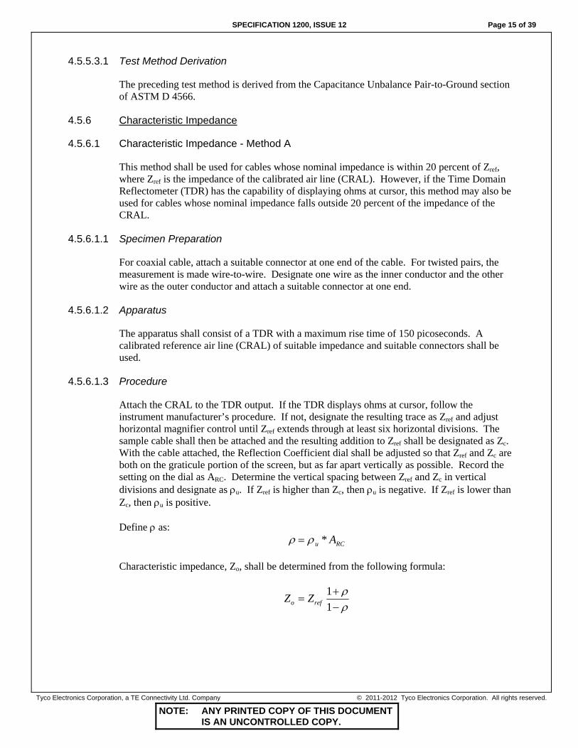
4.5.6.1.3 Procedure
Attach the CRAL to the TDR output. If the TDR displays ohms at cursor, follow the instrument manufacturer’s procedure. If not, designate the resulting trace as Zref and adjust horizontal magnifier control until Zref extends through at least six horizontal divisions. The sample cable shall then be attached and the resulting addition to Zref shall be designated as Zc. With the cable attached, the Reflection Coefficient dial shall be adjusted so that Zref and Zc are both on the graticule portion of the screen, but as far apart vertically as possible. Record the setting on the dial as ARC. Determine the vertical spacing between Zref and Zc in vertical divisions and designate as ρu. If Zref is higher than Zc, then ρu is negative. If Zref is lower than Zc, then ρu is positive. Define ρ as:
ρ ρ= u RCA* Characteristic impedance, Zo, shall be determined from the following formula:
Z Zo ref=+−
11
ρρ

Page 16 of 39 SPECIFICATION 1200, ISSUE 12
NOTE: ANY PRINTED COPY OF THIS DOCUMENT IS AN UNCONTROLLED COPY.
Tyco Electronics Corporation, a TE Connectivity Ltd. Company © 2011-2012 Tyco Electronics Corporation. All rights reserved.
4.5.6.1.4 Test Method Derivation
The preceding test method is derived from the Characteristic Impedance test method in MIL-DTL-17.
4.5.6.2 Characteristic Impedance - Method B
This method shall be used for the determination of the characteristic impedance of coaxial cables only.
4.5.6.2.1 Procedure
The velocity of propagation (Vp) shall be determined in accordance with 4.5.29. The capacitance (C) shall be determined in accordance with 4.5.4. The characteristic impedance shall be determined from the relation:
ZV C pF fto
p
=∗
101670(%) ( / )
4.5.6.2.2 Test Method Derivation
The preceding test method is derived from the Characteristic Impedance test method in MIL-DTL-17.
4.5.6.3 Characteristic Impedance - Method C
This method is appropriate for determination of the characteristic impedance of cables at specified frequencies of 1 MHz or higher.
4.5.6.3.1 Procedure
Using a 1 MHz bridge, determine the capacitance (C) in accordance with 4.5.4. The end of the specimen used to determine the capacitance shall then be shorted and the inductance (L) of the specimen determined using a 1 MHz bridge. Determination of the capacitance and inductance may also be made at other specified frequencies by use of a suitable bridge. For determining the characteristic impedance at frequencies higher than 1 MHz, the sample length should be shortened in order to minimize the effect of resonance. The characteristic impedance, at the specified frequency, shall be determined from the relation:
Z LCo =
Where: Zo is the characteristic impedance in ohms when L is the inductance in henries and C is the capacitance in farads
For multiconductor cables, the capacitance (C) shall be the mutual capacitance (Cm).

SPECIFICATION 1200, ISSUE 12 Page 17 of 39
NOTE: ANY PRINTED COPY OF THIS DOCUMENT IS AN UNCONTROLLED COPY.
Tyco Electronics Corporation, a TE Connectivity Ltd. Company © 2011-2012 Tyco Electronics Corporation. All rights reserved.
4.5.6.3.2 Test Method Derivation
The preceding test method is derived from the Characteristic Impedance test method in MIL-DTL-915.
4.5.6.4 Characteristic Impedance - Method D
This method is appropriate for determination of the characteristic impedance of data bus (balanced pair) cables at specified frequencies of 772 kHz or higher.
4.5.6.4.1 Procedure
Using an appropriate bridge or measurement system, the open circuit impedance (Zoc) and short circuit impedance (Zsc) shall be measured. For determining the characteristic impedance at frequencies higher than 1 MHz, the sample length should be shortened in order to minimize the effect of resonance. The characteristic impedance, at the specified frequency, shall be determined from the relation:
Z Z Zo oc sc= Where: Zo = Complex characteristic impedance in ohms Zoc = Complex open circuit impedance in ohms Zsc = Complex short circuit impedance in ohms
For electrically long lines (more than 1/8 of a wave length), the presence of structural variations influences the impedance observed at the measured end considerably, so that it is not actually Zo but rather an input impedance (Zin). For this situation, least squares function fitting techniques can be used to extract the characteristic impedance from the input impedance.
4.5.6.4.2 Test Method Derivation
The preceding test method is derived from the Characteristic Impedance test method in ASTM D 4566.
4.5.7 Conductor and Shield Continuity
To establish continuity, 25 volts DC, maximum, shall be applied to both ends of each conductor and shield of the cable through an appropriate indicator, such as an ohmmeter, light, or buzzer. The test voltage may be applied to the conductors and shields individually, or in series.
4.5.7.1 Test Method Derivation
The preceding test method is derived from the Continuity test method in MIL-DTL-17.

Page 18 of 39 SPECIFICATION 1200, ISSUE 12
NOTE: ANY PRINTED COPY OF THIS DOCUMENT IS AN UNCONTROLLED COPY.
Tyco Electronics Corporation, a TE Connectivity Ltd. Company © 2011-2012 Tyco Electronics Corporation. All rights reserved.
4.5.8 Conductor and Shield Resistance
Electrical resistance shall be determined on conductors or shields, as applicable, as specified in the applicable specification sheet. Cables containing two or more component wires shall have conductor resistance measured on each conductor prior to cabling, unless otherwise specified. The test procedure shall be in accordance with ASTM B 193. All test results shall be corrected to 20°C, unless otherwise specified.
4.5.9 Dielectric Concentricity
The concentricity of the dielectric insulation shall be determined by first locating and recording the minimum wall thickness measured on a cross section of the dielectric insulation. The maximum wall thickness of this same cross section of dielectric shall also be measured and recorded. All wall thickness measurements shall be made under suitable magnification. The wall thickness shall be the shortest distance between the outer rim of the dielectric insulation and the outer rim of the underlying strand of the conductor. The ratio of the minimum wall thickness to the maximum wall thickness, multiplied by 100, shall define the percent concentricity.
4.5.9.1 Test Method Derivation
The preceding test method is derived from the Concentricity test method in SAE AS22759.
4.5.10 Dielectric/Jacket Elongation and Tensile Strength
Specimens of the dielectric insulation or cable jacket, as applicable, shall be carefully removed and tested for elongation and tensile strength in accordance with ASTM D 3032 using 1-inch (25-mm) bench marks, a 1-inch (25-mm) initial jaw separation, and a jaw separation speed of 2 inches (51 mm) per minute, unless otherwise specified in the applicable specification sheet.
4.5.11 Dimensional Stability
4.5.11.1 Specimen Preparation
A 5-foot (1.5-m), minimum, specimen shall be cut. The ends of the specimen shall be cut squarely and the specimen formed into an 18-inch (457-mm) coil.
4.5.11.2 Procedure
Place the specimen in an air-circulating oven at the temperature specified in the applicable specification sheet and condition for 6 hours. After the conditioning period, remove the specimen from the oven and condition at room temperature for 4 hours. Measure both ends of the specimen for protrusion or contraction of the inner conductor.
4.5.11.3 Test Method
The preceding test method is derived from the Dimensional Stability test method in MIL-DTL-17.
SPECIFICATION 1200, ISSUE 12 Page 19 of 39
NOTE: ANY PRINTED COPY OF THIS DOCUMENT IS AN UNCONTROLLED COPY.
Tyco Electronics Corporation, a TE Connectivity Ltd. Company © 2011-2012 Tyco Electronics Corporation. All rights reserved.
4.5.12 Dimensions
Measurements shall be made on a 12-inch (305-mm), minimum, length of cable. Inner components shall be made accessible by stripping and removing the outer components carefully so as not to nick, cut, or otherwise damage the component to be measured. Four points for measurement shall be located 3 to 4 inches (76 to 102 mm) apart along the component or finished cable specimen length, as applicable. Measurements shall be made at each point at two approximately perpendicular planes or as required to assure that the minimum and maximum reading is attained at each point. A total of eight measurements shall be performed on each specimen. The minimum, maximum, and average values shall be recorded, as applicable. Measurements shall be made with a micrometer, caliper, or any other instrument of equal accuracy.
4.5.12.1 Test Method Derivation
The preceding test method is derived from the Diameter Measurements test method in MIL-DTL-17.
4.5.13 Examination of Product
All samples shall be examined carefully to determine conformance to this specification and to the applicable specification sheet with regard to requirements not covered by specific test methods.
4.5.14 Flammability
Flammability shall be tested in accordance with one of the following procedures as specified in the applicable specification sheet.
4.5.14.1 Flammability - Method A, Vertical Test, Inclined Burner (VW-1)
The test shall be performed in accordance with UL 1581, Section 1080.
4.5.14.2 Flammability - Method B, 60° Test, Inclined Burner
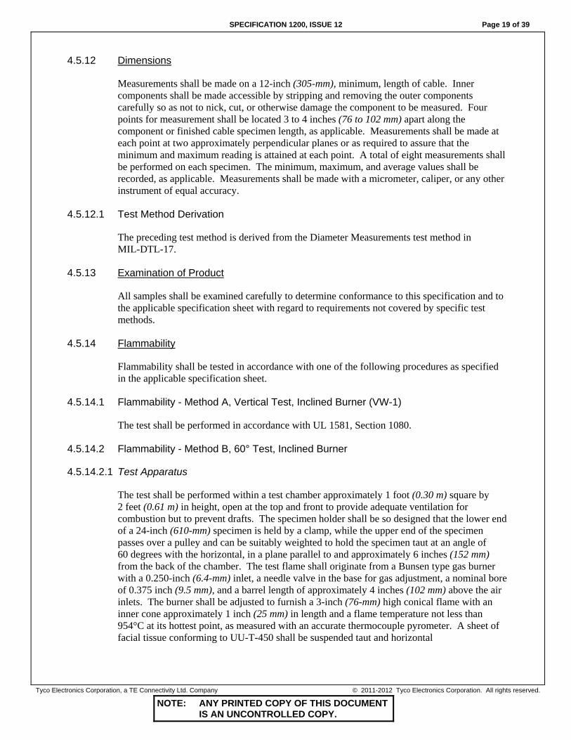
4.5.14.2.1 Test Apparatus
The test shall be performed within a test chamber approximately 1 foot (0.30 m) square by 2 feet (0.61 m) in height, open at the top and front to provide adequate ventilation for combustion but to prevent drafts. The specimen holder shall be so designed that the lower end of a 24-inch (610-mm) specimen is held by a clamp, while the upper end of the specimen passes over a pulley and can be suitably weighted to hold the specimen taut at an angle of 60 degrees with the horizontal, in a plane parallel to and approximately 6 inches (152 mm) from the back of the chamber. The test flame shall originate from a Bunsen type gas burner with a 0.250-inch (6.4-mm) inlet, a needle valve in the base for gas adjustment, a nominal bore of 0.375 inch (9.5 mm), and a barrel length of approximately 4 inches (102 mm) above the air inlets. The burner shall be adjusted to furnish a 3-inch (76-mm) high conical flame with an inner cone approximately 1 inch (25 mm) in length and a flame temperature not less than 954°C at its hottest point, as measured with an accurate thermocouple pyrometer. A sheet of facial tissue conforming to UU-T-450 shall be suspended taut and horizontal

Page 20 of 39 SPECIFICATION 1200, ISSUE 12
NOTE: ANY PRINTED COPY OF THIS DOCUMENT IS AN UNCONTROLLED COPY.
Tyco Electronics Corporation, a TE Connectivity Ltd. Company © 2011-2012 Tyco Electronics Corporation. All rights reserved.
9.5 inches (241 mm) below the point of application of the flame to the specimen and at least 0.50 inch (13 mm) from the chamber floor, so that any material dripping from the specimen shall fall upon the tissue.
4.5.14.2.2 Test Procedure
A 24-inch (610-mm) specimen shall be marked at a distance of 8 inches (203 mm) from its lower end to indicate the point for flame application and shall be placed in the specified 60-degree position in the test chamber. The lower end of the specimen shall be clamped in position in the specimen holder and the upper end shall be passed over the pulley of the holder and the appropriate weight shall be attached. Weight shall be sufficient to hold the specimen taut throughout the test. With the burner held perpendicular to the specimen and at an angle of 30 degrees from the vertical plane of the specimen (see Figure 2), the hottest portion of the flame shall be applied to the lower side of the specimen at the test mark. The period of test flame application shall be 30 seconds and the test flame shall be withdrawn immediately at the end of that period. The distance of flame travel upward along the specimen from the test mark and the time of burning after removal of the test flame shall be recorded; also the presence or absence of flame in the facial tissue due to incendiary dripping from the specimen. Charred holes or charred spots in the tissue shall be ignored in the absence of actual flame. Breaking of the specimen shall not be considered as failure, provided the requirements for flame travel limits, duration of flame, and the absence of incendiary dripping are met.
60°
3 in. (75 mm)
Pulley
Weight
Specimen clampedin place
8 in. (200 mm)
FIGURE 2.
Flammability, Test Apparatus - Method B, 60° Test, Inclined Burner
4.5.14.2.3 Test Method Derivation
The preceding test method conforms to FAR Part 25, Appendix F, Part I, and includes a provision for the detection of incendiary dripping.

SPECIFICATION 1200, ISSUE 12 Page 21 of 39
NOTE: ANY PRINTED COPY OF THIS DOCUMENT IS AN UNCONTROLLED COPY.
Tyco Electronics Corporation, a TE Connectivity Ltd. Company © 2011-2012 Tyco Electronics Corporation. All rights reserved.
4.5.14.3 Flammability - Method C, Horizontal Test, Vertical Burner
4.5.14.3.1 Apparatus
The test shall be performed within a test chamber approximately 14 inches (356 mm) square by 24 inches (610 mm) in height, open at the top and front to provide adequate ventilation for combustion but to prevent drafts. The chamber shall be equipped with supports 12 inches (305 mm) apart, designed to hold a 15-inch (381-mm) specimen in a taut, horizontal position during the test, and located in a plane parallel to and approximately 6 inches (152 mm) from the back of the chamber. The test flame shall originate from a Tirrill type gas burner with a 0.25-inch (6.4-mm) inlet, a needle valve in the base for gas adjustment, a nominal bore of 0.38 inch (9.5 mm) and a barrel length of approximately 4 inches (102 mm) above the air inlets. The burner shall be adjusted to furnish a 5-inch (127-mm) high conical flame with an inner cone approximately 1.5 inches (38 mm) in height.
4.5.14.3.2 Procedure
A 15-inch (381-mm) specimen shall be placed in a horizontal position in the chamber on supports 12 inches (305 mm) apart. Two strips of indicator paper shall be attached to the specimen 10 inches (254 mm) apart, each paper being 5 inches (127 mm) from the point on the specimen where the inner blue cone of the flame is to be applied. The indicator paper shall be moistened sufficiently for proper adhesion and wrapped once around the specimen, with the gummed side towards the specimen, and the ends pasted evenly together and projected 0.75 inch (19 mm) from the specimen on the opposite side to which the flame is to be applied. The Tirrill burner shall be placed in a vertical position and the flame adjusted to 5 inches (127 mm) in height with the inner blue cone 1.5 inches (38 mm) in height. The burner, in a vertical position, shall be placed so that the inner cone just touches the underside of the specimen at a point midway between the two indicator papers. The flame shall be directed against the specimen for exactly 30 seconds and then removed. After flaming of the specimen has ceased, the indicator papers shall be examined to determine the maximum distance the flame extended in either direction from the center point of application of the flame.
4.5.14.3.3 Test Method Derivation
The preceding test method is derived from the Flame Retardance Horizontal test method of CSA Standard C22.2 No. 0.3.
4.5.14.4 Flammability - Method D, 45° Test, Inclined Burner
4.5.14.4.1 Apparatus
A gas burner having a 0.5-inch (13-mm) inlet, a nominal core of 0.4 inches (10 mm), and a length of 4 inches (102 mm) above the primary inlets shall be used. The gas burner shall be adjusted to produce a 4-inch (102-mm) gas flame with an inner cone one-half of its height.
4.5.14.4.2 Procedure
Suspend a 24-inch (610-mm) test specimen in a draft-free chamber such that the specimen is at a 45-degree angle to the vertical wall of the test chamber. The burner shall perpendicular

Page 22 of 39 SPECIFICATION 1200, ISSUE 12
NOTE: ANY PRINTED COPY OF THIS DOCUMENT IS AN UNCONTROLLED COPY.
Tyco Electronics Corporation, a TE Connectivity Ltd. Company © 2011-2012 Tyco Electronics Corporation. All rights reserved.
and in the plane of the specimen. The tip of the inner cone shall be positioned 4 inches (102 mm) from the bottom of the specimen. The flame shall be applied to the specimen for 15 seconds. The afterburn time shall be recorded.
4.5.14.4.3 Test Method Derivation
The preceding test method is derived from the Flame Resistance test method in SAE J1128.
FIGURE 3. Flammability, Test Apparatus - Method D, 45° Test, Inclined Burner
4.5.15 Heat Shock
A 4-inch (102-mm) specimen of finished cable shall be suspended for 4 hours in an air-circulating oven at the temperature specified in the applicable specification sheet. The oven shall have between 8 and 20 or 100 and 200 air changes per hour, and the velocity of air past the specimens shall be between 100 and 200 feet (30 and 61 m) per minute. After conditioning, the specimen shall be removed, cooled to room temperature, and visually examined for evidence of melting or flowing.

SPECIFICATION 1200, ISSUE 12 Page 23 of 39
NOTE: ANY PRINTED COPY OF THIS DOCUMENT IS AN UNCONTROLLED COPY.
Tyco Electronics Corporation, a TE Connectivity Ltd. Company © 2011-2012 Tyco Electronics Corporation. All rights reserved.
4.5.16 Insulation Resistance
Insulation resistance shall be measured on samples of finished cable at least 25 feet (7.6 m) in length. A DC potential between 200 and 500 volts shall be applied between each conductor or shield in the cable and all the other conductors and shields. The leakage current shall be measured after a 2-minute electrification period. However, a stable, or an increasing reading indicating compliance with the specification requirement obtained before the 2-minute period shall be acceptable. The insulation resistance of the test specimen shall be calculated from the following formula:
R MxL=
1000
Where: R = Insulation resistance for 1000 feet (or 1 km) in megohms. M = Reading in megohms. L = Test specimen length, in feet (or meters), measured between outer conductor
ends.
4.5.16.1 Test Method Derivation
The preceding test method is derived from the Insulation Resistance test method in MIL-DTL-17.
4.5.17 Jacket Concentricity and Wall Thickness
The concentricity and wall thickness of the cable jacket shall be determined by first locating and recording the minimum wall thickness measured on a cross section of the jacket. The maximum wall thickness of this same cross section of jacket shall also be measured and recorded. The wall thickness shall be the radial distance between the inner and outer rim of the jacket as measured under suitable magnification. The ratio of the minimum wall thickness to the maximum wall thickness, multiplied by 100, shall define the percent concentricity.
4.5.17.1 Test Method Derivation
The preceding test method is derived from the Concentricity test method in NEMA WC 27500.
4.5.18 Jacket Flaws
4.5.18.1 Impulse Test
Finished cable shall be tested in accordance with ASTM D 3032, Section 13, at the voltage specified in the applicable specification sheet with the shield grounded at one end or both ends. When specified in the contract or order, jacket failure, untested portions, or portions which have been exposed to fewer or more than the specified pulses may be marked by stripping the jacket or by any other suitable method of marking as specified in the contract in lieu of being cut out of the cable.

Page 24 of 39 SPECIFICATION 1200, ISSUE 12
NOTE: ANY PRINTED COPY OF THIS DOCUMENT IS AN UNCONTROLLED COPY.
Tyco Electronics Corporation, a TE Connectivity Ltd. Company © 2011-2012 Tyco Electronics Corporation. All rights reserved.
4.5.18.2 Spark Test
Finished cable shall be passed through a chain electrode spark test device using the voltage specified in the applicable specification sheet at a frequency of 60 or 3000 Hz. For specification sheets specifying a test frequency of 60 Hz only, 3000 Hz may be used alternatively. The shield shall be grounded at one or both ends. The electrode shall be of a suitable bead chain or fine mesh construction that will give intimate metallic contact with practically all the jacket surface. Electrode length and speed of specimen movement shall be such that the jacket is subjected to the test voltage for a minimum of 0.2 second. Any portion showing jacket breakdown shall be cut out, including at least 2 inches (51 mm) of cable on each side of the failure.
4.5.18.2.1 Test Method Derivation
The preceding test method is derived from the Jacket Flaws test method in NEMA WC 27500.
4.5.19 Low Temperature-Cold Bend
One end of a cable specimen shall be secured to a mandrel having a diameter as specified in the applicable specification sheet and placed in a cold chamber. One full turn shall be wrapped around the mandrel and the opposite end shall have sufficient weight attached to keep the cable vertical and tangent to the mandrel during the bending operation. The chamber shall be lowered to the temperature specified in the applicable specification sheet at a rate not to exceed 50°C per minute. The specimen and the mandrel shall be conditioned at this temperature for 4 hours. At the end of this period, and while both the specimen and mandrel are still at this low temperature, the cable shall be wrapped around the mandrel for 180 degrees without opening the chamber. The time for bending around 180 degrees of the mandrel shall be one-half minute at a uniform rate of speed. A revolving mandrel operated externally from the chamber shall be used. The specimen shall then be removed from the mandrel and visually examined, without magnification, for cracks. The specimen, if shielded, shall then be subjected to the voltage withstand test specified in 4.5.30.2.
4.5.19.1 Test Method Derivation
The preceding test method is derived from the Cold Bend test method in NEMA WC 27500.
4.5.20 Partial Discharge (Corona)
Partial discharge extinction voltage (PDEV) shall be defined for this test method as the voltage at which the apparent discharge level falls to 5 picocoulombs or less as the applied voltage is decreased from a value exceeding the inception voltage.
4.5.20.1 Specimen Preparation
A length of cable shall be selected such that the sensitivity of the detecting equipment will permit observation of discharges of 5 picocoulombs or less. The specimen shall be as shown in Figure 4. Similar preparation should be made on triaxial cables.

SPECIFICATION 1200, ISSUE 12 Page 25 of 39
NOTE: ANY PRINTED COPY OF THIS DOCUMENT IS AN UNCONTROLLED COPY.
Tyco Electronics Corporation, a TE Connectivity Ltd. Company © 2011-2012 Tyco Electronics Corporation. All rights reserved.
FIGURE 4.
Partial Discharge (Corona) Sample Preparation
4.5.20.2 Procedure
Connect the specimen to the voltage source so that the voltage is between the conductor and the shield. Triaxial cables shall be connected between the conductor and the first braid. In all cases, the high voltage shall be connected to the conductor or inner shield of the triaxial cable. The frequency of the test voltage shall be between 48 and 62 Hz. The specimen shall be connected to the detecting equipment with the specimen ends immersed in oil until the shield is at least 0.25 inch (6.4 mm) below the surface of the oil. Measurements shall not be made with air bubbles still visible in the oil. Apply the voltage at a maximum rate of 50 volts per second to specimens having a specified PDEV of 3 kV or less, and 100 volts per second for specimens having a specified PDEV above 3 kV. Increase the voltage until partial discharges are detected by the equipment. Then lower the voltage at the same rate until the partial discharges cease. This voltage shall be recorded as the PDEV.
4.5.20.3 Test Method Derivation
The preceding test is derived from the Corona Extinction Voltage test method in MIL-DTL-17.

Page 26 of 39 SPECIFICATION 1200, ISSUE 12
NOTE: ANY PRINTED COPY OF THIS DOCUMENT IS AN UNCONTROLLED COPY.
Tyco Electronics Corporation, a TE Connectivity Ltd. Company © 2011-2012 Tyco Electronics Corporation. All rights reserved.
4.5.21 Propagation Delay
Using an appropriate set-up, follow the equipment manufacturer’s procedure for measuring propagation delay in nanoseconds per unit length at the frequency specified in the applicable specification sheet.
4.5.22 Radiation Resistance
A specimen of finished cable shall be subjected to the electron radiation dosage as specified in the applicable specification sheet at an average rate of between 5 and 10 megarads (50 and 100 kGy) per minute. Following exposure, the center portion of the specimen shall be wound around a mandrel having a diameter as specified in the applicable specification sheet. The ends of the specimen shall extend at least 6 inches (152 mm) beyond the wound portion. Shielded and jacketed specimens shall then be removed from the mandrel without unwinding and shall be subjected to the voltage withstand test of 4.5.30.2. Unshielded, jacketed specimens shall be examined for cracks while still on the mandrel.
4.5.23 Shield Coverage
4.5.23.1 Braided Shields
The percent optical coverage (OC) of the braided shields shall be determined from the following formula:
( )OC F F x= −2 1002
Where:
F EPd ECdL
= =sin sinα α2
Where:
E = Number of strands per carrier α = Angle of strands with axis of cable P = Picks per inch of cable length d = Diameter of strands (or width, if flat strands are used) C = Number of carriers L = Length of lay of strands along cable
and ( ) ( )
tan =2 +2
=+2
α π πD b P
CD b
L
Where:
b = Diameter of strands (or thickness, if flat strands are used) D = Average diameter of cable under shield (see 4.5.12)

SPECIFICATION 1200, ISSUE 12 Page 27 of 39
NOTE: ANY PRINTED COPY OF THIS DOCUMENT IS AN UNCONTROLLED COPY.
Tyco Electronics Corporation, a TE Connectivity Ltd. Company © 2011-2012 Tyco Electronics Corporation. All rights reserved.
4.5.23.2 Spiral Shields
The percent optical coverage (OC) of the spiral shield shall be determined from the following formula:
OC Fx= 100
Where:
F EdL
=sinα
Where:
E = Number of strands d = Diameter of strands (or width, if flat strands are used) L = Length of lay of strands along the cable α = Angle of strands with axis of cable
and
( )tan =
+α
π D bL
Where:
b = Diameter of strands (or thickness, if flat strands are used) D = Average diameter of cable under the shield (see 4.5.12)
4.5.23.3 Test Method Derivation
The preceding test methods are derived from the Shield Coverage test method in NEMA WC 27500.
4.5.24 Skew
A sample of appropriate length shall be tested for skew in accordance with the equipment manufacturer’s procedure. Skew shall be reported in nanoseconds per unit length at the frequency shown on the applicable specification sheet.
4.5.25 Structural Return Loss
4.5.25.1 Specimen Preparation
The specimen shall be of sufficient length to exhibit at least 3 dB attenuation at the lowest frequency required, unless otherwise specified. The specified connectors shall be attached to both ends of the specimen and the assembly connected to a TDR that is capable of producing a step-function rise-time of 150 picoseconds or less. With the far end of the specimen connected to a matched load, the impedance variation exhibited by each cable connector-cable interface shall not be greater than the maximum impedance variation permitted for the cable itself.
Page 28 of 39 SPECIFICATION 1200, ISSUE 12
NOTE: ANY PRINTED COPY OF THIS DOCUMENT IS AN UNCONTROLLED COPY.
Tyco Electronics Corporation, a TE Connectivity Ltd. Company © 2011-2012 Tyco Electronics Corporation. All rights reserved.
4.5.25.2 Procedure
An appropriate test set shall be used to measure the structural return loss of the sample. Calibration and specimen measurements shall be made in accordance with the analyzer or system procedures. The return loss shall be recorded over the specified frequency range.
4.5.25.3 Determination of Compliance
Within the frequency range(s) specified in the applicable specification sheet, the structural return loss shall be not greater than the specified value. (Note: Structural Return Loss is measured in dB. This measurement may be reported as SWR or VSWR and expressed as a ratio.)
4.5.25.4 Test Method Derivation
The preceding test method is derived from the Structural Return Loss test method in MIL-DTL-17.
4.5.26 Surface Transfer Impedance
4.5.26.1 Sample Preparation
Approximately 4 feet (1.2 m) of the cable shall be prepared in the manner described below. Any method of shield termination may be used provided the method is shown to produce results of equal accuracy to that obtained with the method described below.
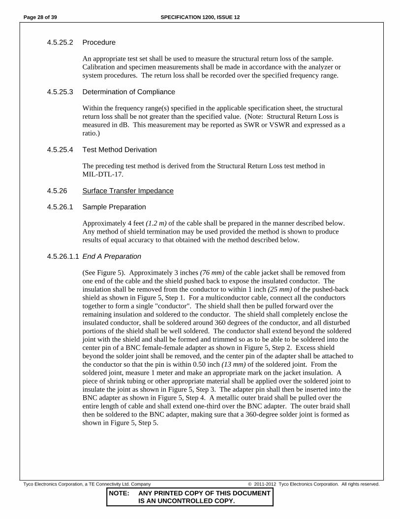
4.5.26.1.1 End A Preparation
(See Figure 5). Approximately 3 inches (76 mm) of the cable jacket shall be removed from one end of the cable and the shield pushed back to expose the insulated conductor. The insulation shall be removed from the conductor to within 1 inch (25 mm) of the pushed-back shield as shown in Figure 5, Step 1. For a multiconductor cable, connect all the conductors together to form a single "conductor". The shield shall then be pulled forward over the remaining insulation and soldered to the conductor. The shield shall completely enclose the insulated conductor, shall be soldered around 360 degrees of the conductor, and all disturbed portions of the shield shall be well soldered. The conductor shall extend beyond the soldered joint with the shield and shall be formed and trimmed so as to be able to be soldered into the center pin of a BNC female-female adapter as shown in Figure 5, Step 2. Excess shield beyond the solder joint shall be removed, and the center pin of the adapter shall be attached to the conductor so that the pin is within 0.50 inch (13 mm) of the soldered joint. From the soldered joint, measure 1 meter and make an appropriate mark on the jacket insulation. A piece of shrink tubing or other appropriate material shall be applied over the soldered joint to insulate the joint as shown in Figure 5, Step 3. The adapter pin shall then be inserted into the BNC adapter as shown in Figure 5, Step 4. A metallic outer braid shall be pulled over the entire length of cable and shall extend one-third over the BNC adapter. The outer braid shall then be soldered to the BNC adapter, making sure that a 360-degree solder joint is formed as shown in Figure 5, Step 5.

SPECIFICATION 1200, ISSUE 12 Page 29 of 39
NOTE: ANY PRINTED COPY OF THIS DOCUMENT IS AN UNCONTROLLED COPY.
Tyco Electronics Corporation, a TE Connectivity Ltd. Company © 2011-2012 Tyco Electronics Corporation. All rights reserved.
4.5.26.1.2 End B Preparation
(See Figure 6). At the other end of the cable, push back the outer braid, over the cable, to expose the mark made 1 meter from the end A conductor solder joint. At the mark, the cable jacket shall be window-stripped for a distance of 0.50 inch (13 mm), 0.25 inch (6 mm) on either side of the mark as shown in Figure 6, Step 1. The outer shield shall then be pulled taut back over the cable and twisted at the end of the cable to hold the outer braid in place. The outer braid shall be soldered to the underlying exposed shield for 360-degrees around the cable at the window cut. Excess outer braid between the solder joint and the end of the cable shall be removed as shown in Figure 6, Step 2. Shrink tubing shall be applied over the entire length of outer braid ensuring that the braid is pressed firmly to the jacket as shown in Figure 5, Step 6. Excess heat shrink tubing shall be removed. The end of the cable shall then be cut and prepared for termination to the N-male connector such that the distance from the installed connector to the window in the cable jacket is as close as possible as shown in Figure 6, Step 3 and Figure 6, Step 4. For multiconductor cables, one conductor shall be prepared for termination to the N connector, the other conductors shall be floating. (Floating conductors in a multiconductor cable is achieved by applying shrink tubing to the exposed ends of the unused conductors.)
4.5.26.2 Configuration
An appropriate test set shall be used to measure the surface transfer impedance of the sample.
4.5.26.3 Procedure
This measurement procedure is suitable for use with a spectrum analyzer and tracking generator. The measurement procedure may be modified as needed if other instruments are used, provided the results are shown to be of equal accuracy to those obtained when the measurements are performed as described below. With the measuring system configured as shown in Figure 7, adjust the output of the signal generator to produce a trace on the spectrum analyzer, which at its highest point is near the top graticule line on the screen. Remove the specimen and insert a calibrated variable attenuator in its place. Adjust the attenuator until a trace is obtained which approximates the top graticule on the screen. The position of the trace shall be recorded, either by storage on the screen or in any other suitable manner. Designate this trace A0, where A0 is the setting of the attenuator in dB. Increase the attenuator setting by 20 dB, and record the position of this trace, designated A20, where A20 is the setting of the attenuator in dB. Increase the attenuator further by 20 dB, and record the position of a trace designated A40. Continue in this manner until the calibration traces have covered the entire height of the screen. Remove the attenuator, and reconnect the specimen as shown in Figure 7. Designate the resulting trace on the screen as S and record its position. The value of S at any frequency shall then be calculated using the following equation:
S A yh
dB mu= + 20

Page 30 of 39 SPECIFICATION 1200, ISSUE 12
NOTE: ANY PRINTED COPY OF THIS DOCUMENT IS AN UNCONTROLLED COPY.
Tyco Electronics Corporation, a TE Connectivity Ltd. Company © 2011-2012 Tyco Electronics Corporation. All rights reserved.
Where: Au = Attenuator setting used to produce the calibration trace immediately above
trace S. y = Distance on the screen between the traces Au and S. h = Distance on the screen between trace Au and the calibration trace immediately
below trace S.
The power of attenuation P of the shield is:
P S= 10 10 The surface transfer impedance Zt, at the frequency chosen, is given by:
Z Z Pt = 0
2 ohms / meter
Where: Z0 = Characteristic impedance of the spectrum analyzer and tracking generator.
Unless otherwise specified, 100 points uniformly spaced throughout the decade of frequency, and including the beginning and end of the decade, shall be taken for each decade of frequency range specified in the applicable specification sheet.
4.5.26.4 Determination of Compliance
The values of Zt, as determined from measurements made in accordance with 4.5.26.3, shall not exceed the maximum specified values of Zt as shown on the applicable specification sheet in any of the following ways: a. A single maximum value of Zt may be specified at a discrete frequency or over a range of
frequencies. b. The maximum value of Zt over a range of frequencies may be specified by a plot of the
maximum value of Zt versus frequency. c. The maximum value of Zt over a range of frequencies specified by a curve defined by the
maximum value of Zt at given frequencies. d. The maximum value of Zt over a range of frequencies may be specified from the following
equation:
Maximum specified Zt = Az( f ) Bz milliohms/meter
Where: f = Frequency in MHz Az, Bz = Zt calculation parameters specified in the applicable specification sheet
4.5.26.5 Test Method Derivation
The preceding test method is derived from the Surface Transfer Impedance test method in SAE AS85485.

SPECIFICATION 1200, ISSUE 12 Page 31 of 39
NOTE: ANY PRINTED COPY OF THIS DOCUMENT IS AN UNCONTROLLED COPY.
Tyco Electronics Corporation, a TE Connectivity Ltd. Company © 2011-2012 Tyco Electronics Corporation. All rights reserved.
FIGURE 5.
Preparation of Cable End A

Page 32 of 39 SPECIFICATION 1200, ISSUE 12
NOTE: ANY PRINTED COPY OF THIS DOCUMENT IS AN UNCONTROLLED COPY.
Tyco Electronics Corporation, a TE Connectivity Ltd. Company © 2011-2012 Tyco Electronics Corporation. All rights reserved.
Step 1
Step 2
Step 3
Step 4
FIGURE 6. Preparation of Cable End B
SignalGenerator 10 dB Pad Specimen Detector
A B
FIGURE 7. Configuration of the measurement system for determining surface transfer impedance. The letters “A” and “B” refer to the A and B ends of the specimen as described in paragraph 4.5.26.1.

SPECIFICATION 1200, ISSUE 12 Page 33 of 39
NOTE: ANY PRINTED COPY OF THIS DOCUMENT IS AN UNCONTROLLED COPY.
Tyco Electronics Corporation, a TE Connectivity Ltd. Company © 2011-2012 Tyco Electronics Corporation. All rights reserved.
4.5.27 Time Delay
Time delay (TD), in nanoseconds per foot, shall be determined from the following formula:
TDVp
=10167.
(%)
Where: Vp = Velocity of propagation as determined by 4.5.29.
4.5.28 Vacuum Stability
Specimens of finished cable shall be tested in accordance with ASTM E 595.
4.5.29 Velocity of Propagation
4.5.29.1 Specimen Preparation
The sample cable shall be of suitable length, 10 feet (3 m), minimum. At one end of the cable, the center conductor and shield shall be connected together. For a twisted pair, the conductors shall be twisted together and the shield left unconnected. At the other end of the cable, one conductor shall be designated as the center conductor and the other conductor as the outer conductor. The sample length shall be defined as the length of cable covered by the shield. For an unshielded twisted pair, tape the components together 0.50 inch (13 mm) from each end of the cable. The sample length shall be defined as the length of cable between the outside edges of the tape. The sample length shall be measured and designated as L.
4.5.29.2 Procedure
The free end of the cable shall be attached to a "T"-type connector. One leg of the T shall be attached to a detector and the other leg to a signal generator. The signal generator shall be adjusted to a frequency of 1 MHz and the frequency shall then be increased until a sharp decrease in the detector reading is observed. The frequency generator shall be adjusted until a minimum in the detector reading is achieved. This frequency shall be recorded to the nearest 0.1 MHz. Designate this reading as f1. The frequency of the signal generator shall be increased further until another decrease in the detector reading is observed. The frequency of the minimum detector reading shall be recorded as f2. This procedure shall be repeated until at least four different frequencies are recorded.
4.5.29.3 Calculations
At each recorded frequency, the frequency in MHz shall be divided by the subscript number and the results recorded.
f ff ff ff fetc
1 01
2 02
3 03
4 04
1=2 =3 =4 =
.

Page 34 of 39 SPECIFICATION 1200, ISSUE 12
NOTE: ANY PRINTED COPY OF THIS DOCUMENT IS AN UNCONTROLLED COPY.
Tyco Electronics Corporation, a TE Connectivity Ltd. Company © 2011-2012 Tyco Electronics Corporation. All rights reserved.
The mean value of all the resulting frequencies shall be calculated and designated as f_
. The velocity of propagation (Vp) shall be determined from the following formula:
V L f L fp
m f=2299 8
2_ _
. or
983.6 %
Where:
Lm = Specimen length in meters Lf = Specimen length in feet
4.5.29.4 Test Method Derivation
The preceding test method is derived from the Time Delay test method in MIL-DTL-17.
4.5.30 Voltage Withstand
Voltage withstand tests shall be made using an AC source with a frequency of 50 or 60 Hz. The voltage specified in the applicable specification sheet shall be applied for 1 minute.
4.5.30.1 Voltage Withstand (Dielectric)
Voltage withstand (dielectric) tests shall be performed upon finished cable by applying the specified voltage between each conductor or shield in turn, and all other conductors and shields which shall be tied together and grounded. There shall be no dielectric breakdown.
4.5.30.2 Voltage Withstand (Post Environmental)
Voltage withstand (post environmental) tests on the outer jacket shall be performed after the finished cable has been immersed in a 5-percent, by weight, solution of sodium chloride in water at room temperature for at least 1 hour, and while the cable is still immersed. The specified voltage shall be applied between all the conductors and shields, tied together, and the water bath which shall be grounded.
4.5.30.3 Test Method Derivation
The preceding test methods are derived from the Dielectric Withstand and Voltage Withstand, Jacket, test methods in NEMA WC 27500.
4.5.31 Weight
The weight of each lot of finished cable shall be determined by Procedure I (4.5.31.1). Lots failing to meet the weight requirement of the applicable specification sheet when tested in accordance with Procedure I shall be subjected to Procedure II (4.5.31.2). All spools or reels failing to meet the requirements of the applicable specification sheet when tested to Procedure II shall be rejected.

SPECIFICATION 1200, ISSUE 12 Page 35 of 39
NOTE: ANY PRINTED COPY OF THIS DOCUMENT IS AN UNCONTROLLED COPY.
Tyco Electronics Corporation, a TE Connectivity Ltd. Company © 2011-2012 Tyco Electronics Corporation. All rights reserved.
4.5.31.1 Procedure I
A length of cable, sufficient to produce a measured weight to at least 3 significant figures, shall be weighed and converted to the weight per unit length shown on the applicable specification sheet.
4.5.31.2 Procedure II
The net weight of the finished cable on each spool or reel shall be obtained by subtracting the tare weight of the spool or reel from the gross weight of the spool or reel containing the finished cable. The net weight of cable on each spool or reel shall be divided by the accurately determined length of finished cable on that spool or reel and the resultant figure converted to the weight per unit length shown on the applicable specification sheet. When wood or other moisture absorbent materials are used for spool or reel construction, weight determinations shall be made under substantially uniform conditions of relative humidity.
4.5.31.3 Test Method Derivation
The preceding test methods are derived from the Wire Weight test methods in SAE AS22759.
4.5.32 Weight Loss
A 5-foot (1.5-m) length of shielded cable shall be flush cut and weighed to the nearest 0.001 grams. Prior to weighing, the jacket surface of cables with jackets may be wiped clean with a suitable low boiling solvent such as isopropyl alcohol to remove any accumulation of debris. If a wipe is performed, the test specimen should be allowed to re-equilibrate to ambient conditions for 30 minutes. After cleaning, the sample should be handled using cotton gloves to avoid any contamination with finger oils. The cable jacket, if any, shall be removed by longitudinally slitting with a razor blade or a similar tool. After removal, the jacket and shielded inner bundle shall be wrapped into a loose coil and suspended in a forced air flow oven at 250 ± 2ºC for 20 minutes. After this conditioning, the collective test specimen shall be allowed to cool to ambient conditions for 30 minutes and then reweighed to the nearest 0.001 grams. The percent weight loss shall be calculated from the following formula:
(Original Weight - Final Weight) % Weight Loss = Original Weight x 100
4.5.33 Wrap Coverage
The coverage of a tape wrap shall be expressed as the percentage by which one turn of the tape overlaps the previous turn, and shall be determined from the following formula:
Overlap ab
x= 100%
Where:
a = Distance, measured perpendicular to the edge of the tape, by which one turn of the tape overlaps the next
b = Width of the tape

Page 36 of 39 SPECIFICATION 1200, ISSUE 12
NOTE: ANY PRINTED COPY OF THIS DOCUMENT IS AN UNCONTROLLED COPY.
Tyco Electronics Corporation, a TE Connectivity Ltd. Company © 2011-2012 Tyco Electronics Corporation. All rights reserved.
Alternatively:
Overlap cd
x= −⎛⎝⎜
⎞⎠⎟
1 100%
Where:
c = Distance between adjacent visible tape edges measured along the axis of the cable d = Width of the tape measured along the axis of the cable
5. STANDARD PACKAGING
Unless otherwise specified (see 6.1), the following shall define the standard spooling and labeling requirements for cable furnished under this specification. Standard shipping tolerance on ordered quantity shall be ± 10 percent.
5.1 SPOOLING REQUIREMENTS
All layers of cable shall be wound on spools or reels (see 5.1.1) with sufficient tension to prevent shifting of layers and creation of crossovers within layers. Finished cable lengths shall be wound on spools or reels with all ends exposed. There shall be no more than 5 lengths per spool or reel and no length shall be less than 50 feet (15 m).
5.1.1 Spools and Reels
Spools and reels shall be of a nonreturnable type. Each spool and reel shall have an appropriate diameter for the respective wire or cable size. In no case shall the barrel of the spool or reel have a diameter less than 3.5 inches (89 mm). Spools and reels shall be suitably finished to prevent corrosion under typical storage and handling conditions. Loaded plastic spools shall not exceed 50 pounds (23 kg). Loaded wooden reels shall have no weight restriction.
5.1.2 Containers
Unless otherwise specified (see 6.1), finished cable shall be delivered in standard commercial containers so constructed as to ensure acceptance by common or other carrier for safe transportation at the lowest rate to the point of delivery.
5.2 LABELING REQUIREMENTS
All spools and reels shall be identified with the following information:
Manufacturer's Part Number Lot Number Quantity in Feet (or Meters) Name of Manufacturer

SPECIFICATION 1200, ISSUE 12 Page 37 of 39
NOTE: ANY PRINTED COPY OF THIS DOCUMENT IS AN UNCONTROLLED COPY.
Tyco Electronics Corporation, a TE Connectivity Ltd. Company © 2011-2012 Tyco Electronics Corporation. All rights reserved.
6. NOTES
6.1 ORDERING DATA
Procurement documents should specify the following: a. Title, number, and revision of this specification b. Applicable specification sheet part number c. Quantity d. Special preparation for delivery requirements, if applicable (see Section 5)
6.2 METRIC UNITS
Metric units (where shown in parentheses) are for information only.
6.3 TEST METHOD DERIVATIONS
Test method derivations contained in test methods are shown for information only.
6.4 TRADEMARKS
Raychem, TE Connectivity, TE connectivity (logo), and TE (logo) are trademarks.

Page 38 of 39 SPECIFICATION 1200, ISSUE 12
NOTE: ANY PRINTED COPY OF THIS DOCUMENT IS AN UNCONTROLLED COPY.
Tyco Electronics Corporation, a TE Connectivity Ltd. Company © 2011-2012 Tyco Electronics Corporation. All rights reserved.
6.5 SYMBOLS
The following symbols and prefixes are used in this specification and are listed below for information.
6.5.1 Standard Prefixes
Symbol Prefix Multiplier M mega 106 k kilo 103 d deci 10-1 c centi 10-2 m milli 10-3 μ micro 10-6 n nano 10-9 p pico 10-12 f femto 10-15
6.5.2 Standard Symbols
Symbol Name B bel Bm bel (relative to 1 milliwatt) C coulomb °C degrees, Celsius °F degrees, Fahrenheit eV electron-volt ft. foot F farad g gram Hz hertz in. inch m meter psi pounds per square inch s second V volt Ω ohm

SPECIFICATION 1200, ISSUE 12 Page 39 of 39
NOTE: ANY PRINTED COPY OF THIS DOCUMENT IS AN UNCONTROLLED COPY.
Tyco Electronics Corporation, a TE Connectivity Ltd. Company © 2011-2012 Tyco Electronics Corporation. All rights reserved.
6.5.3 Electrical Symbols
Symbol Description a1, a2 Attenuation formula coefficients ac Alternating current A0, A20,… Calibrated attenuator settings, dB A(f) Attenuation at frequency (f) Au Calibrated attenuator setting, dB Az Zt calculation parameter Bz Zt calculation parameter C Calculated or measured capacitance Ca, Cb, Cc, Cd Measured capacitances Cag, Cbg Measured capacitance, conductor to ground Cap, Cbp Measured capacitance, conductor to pair Cm Mutual capacitance, calculated Cu Capacitance unbalance, calculated Cu1, Cu2, etc. Capacitance unbalance, % CuL Pair-to-pair capacitance unbalance, measured Cupg Pair-to-ground capacitance unbalance, calculated CRAL Calibrated reference air line dc Direct current f Frequency (MHz) f1, f2,… Resonant frequency (MHz) h Measurement on spectrum analyzer screen L Calculated or measured inductance M Leakage current reading in megohms P Power ratio PDEV Partial discharge extinction voltage R Insulation resistance, calculated S Calculated attenuation SWR Standing wave ratio TD Time delay TDR Time domain reflectometer VSWR Voltage standing wave ratio Vp Velocity of propagation, % y Measurement on spectrum analyzer screen Y Pair-to-ground capacitance unbalance, measured Y1 Pair-to-ground capacitance unbalance per 1000 feet (km) Zin Input impedance Zo Characteristic impedance Zos Open circuit impedance, measured Zsc Short circuit impedance, measured Zref Reference characteristic impedance Zt Surface transfer impedance ρ Reflection coefficient, calculated ρu Reflection coefficient, un-scaled


![sa1s3.patientpop.com · Asthma [2 Emphysema Bronchitis HIV+ Cl Eating Disorder Other: Frequency Arthritis Diabetes: Cl Diet Controlled Pill Controlled C] Insulin Controlled High Blood](https://static.fdocuments.us/doc/165x107/5f0bfb637e708231d4332cf2/sa1s3-asthma-2-emphysema-bronchitis-hiv-cl-eating-disorder-other-frequency-arthritis.jpg)