CABLE ACCESSORIES IN UNDERGROUND MEDIUM · PDF fileCABLE ACCESSORIES IN UNDERGROUND MEDIUM...
12
CABLE ACCESSORIES IN UNDERGROUND MEDIUM VOLTAGE DISTRIBUTION NETWORKS Terminaon Separable connector Joint Branch joint europacable Rue Marie de Bourgogne 58 — B-1000 Brussels — www.europacable.eu — EU Transparency Register ID 4543103789-92
Transcript of CABLE ACCESSORIES IN UNDERGROUND MEDIUM · PDF fileCABLE ACCESSORIES IN UNDERGROUND MEDIUM...

CABLE ACCESSORIES IN UNDERGROUND MEDIUM VOLTAGE
DISTRIBUTION NETWORKS
Termination Separable connector
Joint
Branch joint
europacable Rue Marie de Bourgogne 58 — B-1000 Brussels — www.europacable.eu — EU Transparency Register ID 4543103789-92

europacable Rue Marie de Bourgogne 58 — B-1000 Brussels — www.europacable.eu — EU Transparency Register ID 4543103789-92
What is “Medium Voltage”?
Cables accessories are used to connect MV cable networks. Accessories are classified as: • Terminations to connect the end of a cable to another element of the network. This could
be a connection to switchgear, a transformer, an overhead line etc. Terminations are of three main types: ◦ Indoor terminations (protected from exposure to the weather and UV radiation) ◦ Outdoor terminations (exposed to the weather and UV radiation) ◦ Separable connectors (elbow, straight and T-connectors)
• Joints (splices), to connect cables together. Joints are of three main types and may be buried or installed above ground: ◦ Straight joints to connect identical cables ◦ Transition joints to connect cables of different construction ◦ Branch joints, to branch a link to another
Functions performed by the accessoryCable accessories an integral part of a distribution network and must perform the same basic functions as the cable on which they are installed. They are required to:• transmit electrical power through the current in the conductor. Full rated current and short
circuit currents must be carried without overheating• insulate the conductor from direct contact to earth• provide electrical stress control at cable screen ends within the joint or termination• ensure protection from mechanical damage to buried joints• protect against water ingress, both for buried or non-buried accessories• protect terminations, mainly outdoor type, against the environment (rain, pollution, UV
radiation etc).
Cable accessories should not be weak links in the network. They are designed and tested with the intention that their useful life will not be less than that of the associated cables. Cable networks are expected to have a working life of not less than 30 years.
Primary selection criteriaThe choice of an accessory is based on the cable type(s) used in the network.Up to the 1970s, MV cables were insulated with impregnated paper contained within a lead or aluminium sheath. The accessories were adapted on site for each cable type and were mainly hand crafted by highly skilled jointers.The development of cables with extruded polymeric (plastic) insulation, both single-core and 3-core, has fundamentally modified the design of accessories, using new materials and having very different installation techniques.
What is an MV cable accessory?
Medium Voltage (MV) is a term used for a range of electricity distribution system voltages from 6 kV up to 36 kV. Cable accessories for this voltage range have similar design and performance requirements that distinguish them from accessories for ‘low voltage’ (typically 1 kV) and those for “high voltage” (typically 72 kV and above).
europacable Rue Marie de Bourgogne 58 — B-1000 Brussels — www.europacable.eu — EU Transparency Register ID 4543103789-92
The use of cross-linked polyethylene (XLPE) as the most common primary insulation of MV cables has simplified the choice of suitable accessories. Many accessories or major accessory components are now pre-manufactured, thus reducing the time and skill needed for installation in the field.Reliability is an essential factor. Accessories must be qualified through standard testing programmes. In addition, proven field experience is highly valued.Choices may then be based on economic considerations. However, over a 30 year service life the initial cost of the accessories is small in relation to the cost of a network failure and repair.Last but not least, the choice depends upon the skill and experience of the jointers who are to perform the work, since the main cause of accessory failure is inaccurate or poor quality installation. Installation time and simplicity of installation can also be selection criteria.
Accessory designDesign can be conveniently summarized by reference to the functions required of the accessory.
Electrical insulation materials must have special electrical and mechanical properties appropriate to their function in the joint or termination.Commonly used polymeric materials are silicone rubbers, ethylene propylene diene monomer (EPDM) rubber and cross-linked thermoplastics. These may be modified to impart special properties such as electrical conductivity and resistance to weathering and UV radiation.
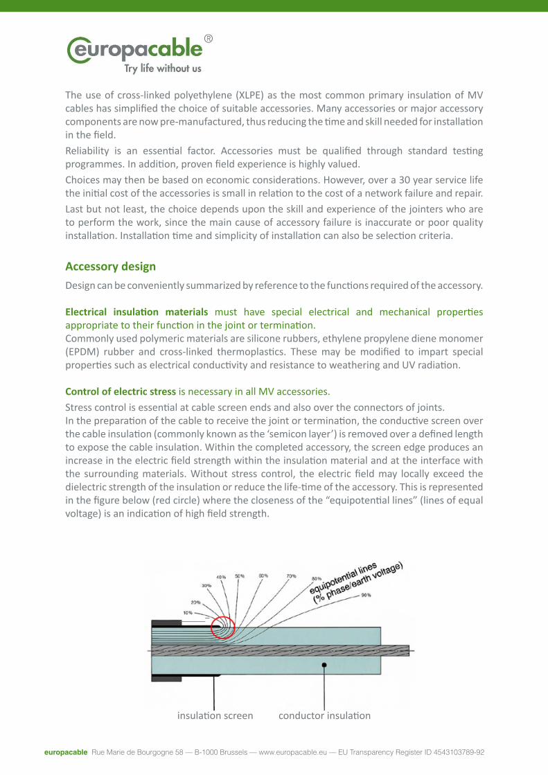
Control of electric stress is necessary in all MV accessories.Stress control is essential at cable screen ends and also over the connectors of joints. In the preparation of the cable to receive the joint or termination, the conductive screen over the cable insulation (commonly known as the ‘semicon layer’) is removed over a defined length to expose the cable insulation. Within the completed accessory, the screen edge produces an increase in the electric field strength within the insulation material and at the interface with the surrounding materials. Without stress control, the electric field may locally exceed the dielectric strength of the insulation or reduce the life-time of the accessory. This is represented in the figure below (red circle) where the closeness of the “equipotential lines” (lines of equal voltage) is an indication of high field strength.
insulation screen conductor insulation

europacable Rue Marie de Bourgogne 58 — B-1000 Brussels — www.europacable.eu — EU Transparency Register ID 4543103789-92
conductive stress cone insulating rubber
Another common way to achieve stress control is to apply a layer with special electrical impedance characteristics. The layer overlaps the screen edge and extends along the exposed cable insulation for a defined length. The material will have relative permeability significantly higher than the insulation material and may have non-linear resistance properties. A combination of resistive and capacitive characteristics creates a smooth linear voltage gradient along the layer. This type of stress control may typically be provided in the accessory kit in the form of a polymer sleeve (heat-shrinkable or cold-shrinkable) or a mastic.
insulation screen edgehigh permittivity layer
insulation
The original method of controlling electric stress at the screen edge was to construct a cone of insulating material with a conductive layer on the outer surface of the cone. The conductive layer of the cone overlaps and contacts the cable screen edge, reducing the electric stress at this position to a safe level. Stress cones were originally made of impregnated paper tapes or rolls but are now flexible rubber components that are slid on to the cable and located over the screen edge.
Stress control may also be required over the connector within a joint or a separable connector. It is achieved using the same principles and materials as described above. In some accessory designs the conductor connector is completely enclosed by a conductive surface known as a ‘Faraday cage’. In other designs, the stress control layer in a joint may be continuous over the length of the joint, overlapping both screen edges and the conductor connector.
europacable Rue Marie de Bourgogne 58 — B-1000 Brussels — www.europacable.eu — EU Transparency Register ID 4543103789-92
Conductor connectors are at the heart of all accessoriesCable conductors are nowadays connected with compression connectors or mechanical connectors. The connection, which is a primary function of the accessory, is a potential cause of failure by ‘thermal runaway’. If the connection is not correctly made, thermal cycles produce a progressive increase in the contact resistance which is cumulative and will lead to failure. In addition to a low resistance connection, it is understandable that to reduce the risk of thermal runaway the accessory should not provide extra thermal insulation over the connector compared to that of the cable.For distribution networks, cable conductors are made of aluminum or copper. Although the electrical resistance of aluminium is greater than that of copper, aluminium is lighter and historically cheaper than copper, hence its widespread use for this application. Comparative values are shown in the table below.
Conductivity (copper base 100) Relative density (water = 1)
Aluminium 61 2,7Copper 100 8,9
For connections, aluminium has the disadvantage that it is coated by its oxide, alumina, which is a good insulating material. The connector must break this coating to achieve a good low resistance connection.
• Soldered connectionsThis was the traditional method of jointing paper insulated cables, requiring highly skilled jointers. After tinning, the conductor and the connector were soldered with lead/tin alloy. Well done, it was an excellent technique but limited the maximum conductor temperature to 160°C under short circuit conditions. With today’s extruded cables, the standard is 250°C.
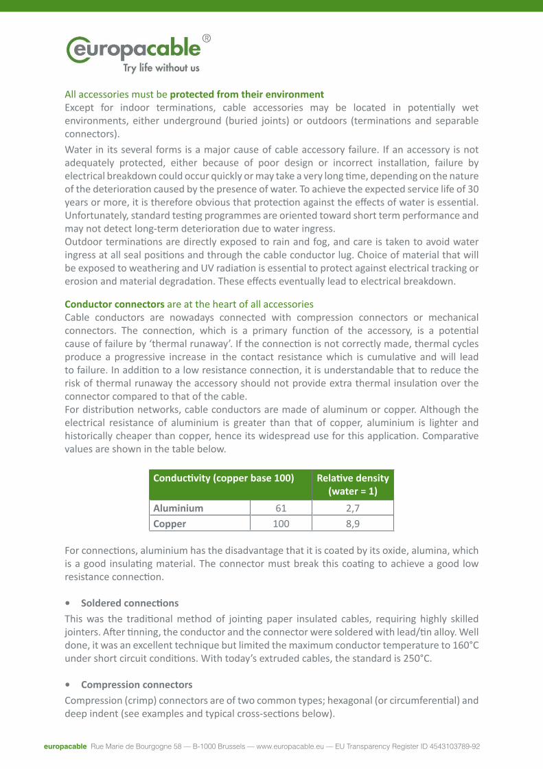
• Compression connectorsCompression (crimp) connectors are of two common types; hexagonal (or circumferential) and deep indent (see examples and typical cross-sections below).
All accessories must be protected from their environment Except for indoor terminations, cable accessories may be located in potentially wet environments, either underground (buried joints) or outdoors (terminations and separable connectors).Water in its several forms is a major cause of cable accessory failure. If an accessory is not adequately protected, either because of poor design or incorrect installation, failure by electrical breakdown could occur quickly or may take a very long time, depending on the nature of the deterioration caused by the presence of water. To achieve the expected service life of 30 years or more, it is therefore obvious that protection against the effects of water is essential. Unfortunately, standard testing programmes are oriented toward short term performance and may not detect long-term deterioration due to water ingress.Outdoor terminations are directly exposed to rain and fog, and care is taken to avoid water ingress at all seal positions and through the cable conductor lug. Choice of material that will be exposed to weathering and UV radiation is essential to protect against electrical tracking or erosion and material degradation. These effects eventually lead to electrical breakdown.
europacable Rue Marie de Bourgogne 58 — B-1000 Brussels — www.europacable.eu — EU Transparency Register ID 4543103789-92
Connectors for aluminium conductors are also made of aluminium, and it is the deformation of the conductor which breaks the oxide coating. Connection of copper conductors with compression connectors is done in the same way, but copper connectors do not have the oxidation drawbacks found with aluminium.Successful installation of compression connectors does not require a long training and is less skill-sensitive than soldering. Nevertheless, it is absolutely necessary to use the right die with properly calibrated tooling. These are a potential source of errors leading to failure.
Hydraulic tooling is heavy and bulky, which is a disadvantage of the method. Connectors must be carefully selected according to the size and shape of conductors and each connector is generally not able to accommodate more than one conductor size.
• Mechanical connectorsThe use of mechanical connectors is rapidly gaining ground today because they have significant advantages over other techniques. Mechanical connectors: • avoid the need for special tooling• extend the application range each connector to more than one conductor sizePrior to its introduction in MV accessories, this technology was already widely used in low voltage accessories, where overall connector shape and dimensions are not so critical.
Screws in the connector body apply pressure to the conductor (see below). They are generally designed so that the screw head or other part of the body breaks at a pre-determined applied torque. This ensures a reproducible pressure without the need for calibrated tooling. Compared with other connection technologies, mechanical connectors rely least on the skill of the jointer.
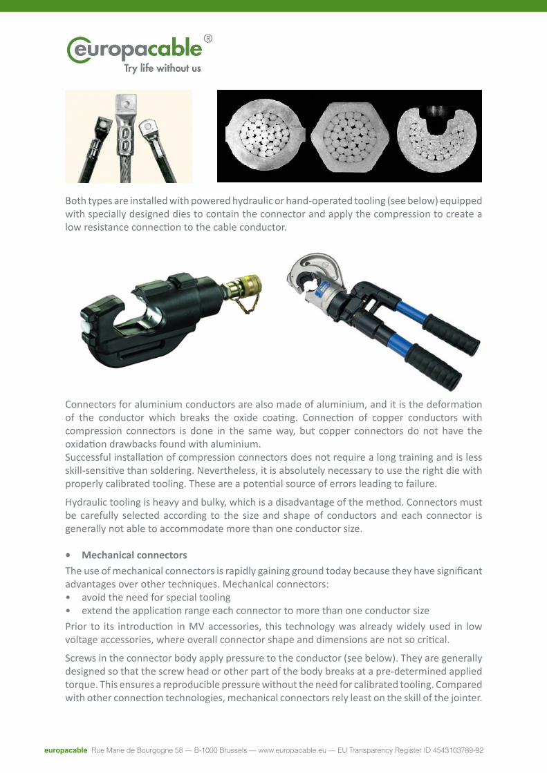
Both types are installed with powered hydraulic or hand-operated tooling (see below) equipped with specially designed dies to contain the connector and apply the compression to create a low resistance connection to the cable conductor.

europacable Rue Marie de Bourgogne 58 — B-1000 Brussels — www.europacable.eu — EU Transparency Register ID 4543103789-92
Paper insulated cablesMV cables for distribution networks installed up to the second half of the 20th century were insulated by special paper applied as multiple layers of tape. The insulation body was then impregnated with insulating oil or compound. The viscosity of the oil compounds varied depending upon manufacturing process and local choices. The paper insulation was protected by a continuous metallic sheath made of lead or aluminium.
Jointing of these cables was done by:• welding or soldering of the conductors;• taping of impregnated paper to provide insulation over the connector and prepared cable
ends;• installation of a lead sleeve over each phase or over all three phases, soldered to the lead
sheath of the cable (see below) and filled with an insulating compound;
• fitting of a cast iron moulded casing for mechanical protection (see below);• filling the casing with hot bitumen or a synthetic resin.
The components for these accessories were not expensive, but a long training process was required for the jointers. If correctly installed, these accessories were highly reliable.
Evolution of MV cable accessories
A single connector may cover a wide range of cable sizes, for example from 95 mm2 to 240 mm2. Most MV connectors are made of aluminium (tinned or bare) and can be used to connect either aluminium or copper conductors.
The size application range and the possibility to connect aluminium or copper conductors with the same connector permits a large inventory reduction and also the possible inclusion of connectors within the accessory kit. Inclusion of mechanical connectors in the kit removes the risk of incorrect connector choice and therefore contributes to the overall reliability of the network.
europacable Rue Marie de Bourgogne 58 — B-1000 Brussels — www.europacable.eu — EU Transparency Register ID 4543103789-92
Prefabricated MV cable accessories on extruded (polymeric) cablesAt the end of the 1970s, XLPE insulated cables started to be widely used in Japan, Europe and United States.Transition joints between these new cables and old paper insulated cables required careful design because the oil compound is not compatible with polymeric materials. Other accessories to be used on networks comprising only extruded synthetic cables rapidly evolved through the use of new materials and techniques.At first, self-amalgamating rubber tapes were used as the primary insulation in joints, with cast resin to protect against water and mechanical damage. The need for simplification and time-saving then led to the design of accessories incorporating pre-manufactured components to simplify installation and in some cases allow electrical testing as part of the manufacturing process.These accessories where either:• Heat-shrink, based on cross-linked thermoplastics• Pre-moulded, made of ethylene propylene diene monomer (EPDM) rubber or silicone
rubbers• Cold-shrink, with flexible rubber components typically made of silicone rubber or ethylene
propylene diene monomer (EPDM) rubber held expanded on rigid formers
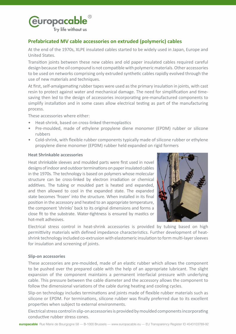
Heat Shrinkable accessories
Electrical stress control in heat-shrink accessories is provided by tubing based on high permittivity materials with defined impedance characteristics. Further development of heat-shrink technology included co-extrusion with elastomeric insulation to form multi-layer sleeves for insulation and screening of joints.
Slip-on accessoriesThese accessories are pre-moulded, made of an elastic rubber which allows the component to be pushed over the prepared cable with the help of an appropriate lubricant. The slight expansion of the component maintains a permanent interfacial pressure with underlying cable. This pressure between the cable diameter and the accessory allows the component to follow the dimensional variations of the cable during heating and cooling cycles.Slip-on technology includes terminations and joints made of flexible rubber materials such as silicone or EPDM. For terminations, silicone rubber was finally preferred due to its excellent properties when subject to external environments.Electrical stress control in slip-on accessories is provided by moulded components incorporating conductive rubber stress cones.
Heat shrinkable sleeves and moulded parts were first used in novel designs of indoor and outdoor terminations on paper insulated cables in the 1970s. The technology is based on polymers whose molecular structure can be cross-linked by electron irradiation or chemical additives. The tubing or moulded part is heated and expanded, and then allowed to cool in the expanded state. The expanded state becomes ‘frozen’ into the structure. When installed in its final position in the accessory and heated to an appropriate temperature, the component ‘shrinks’ back to its original dimensions and forms a close fit to the substrate. Water-tightness is ensured by mastics or hot-melt adhesives.
europacable Rue Marie de Bourgogne 58 — B-1000 Brussels — www.europacable.eu — EU Transparency Register ID 4543103789-92
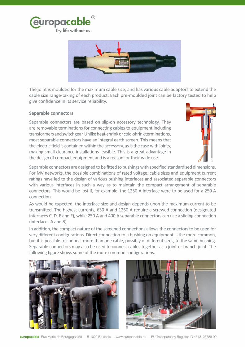
The joint is moulded for the maximum cable size, and has various cable adaptors to extend the cable size range-taking of each product. Each pre-moulded joint can be factory tested to help give confidence in its service reliability.
Separable connectors
Separable connectors are based on slip-on accessory technology. They are removable terminations for connecting cables to equipment including transformers and switchgear. Unlike heat-shrink or cold-shrink terminations, most separable connectors have an integral earth screen. This means that the electric field is contained within the accessory, as is the case with joints, making small clearance installations feasible. This is a great advantage in the design of compact equipment and is a reason for their wide use.
Separable connectors are designed to be fitted to bushings with specified standardised dimensions. For MV networks, the possible combinations of rated voltage, cable sizes and equipment current ratings have led to the design of various bushing interfaces and associated separable connectors with various interfaces in such a way as to maintain the compact arrangement of separable connectors. This would be lost if, for example, the 1250 A interface were to be used for a 250 A connection.As would be expected, the interface size and design depends upon the maximum current to be transmitted. The highest currents, 630 A and 1250 A require a screwed connection (designated interfaces C, D, E and F), while 250 A and 400 A separable connectors can use a sliding connection (interfaces A and B).In addition, the compact nature of the screened connections allows the connectors to be used for very different configurations. Direct connection to a bushing on equipment is the more common, but it is possible to connect more than one cable, possibly of different sizes, to the same bushing. Separable connectors may also be used to connect cables together as a joint or branch joint. The following figure shows some of the more common configurations.
europacable Rue Marie de Bourgogne 58 — B-1000 Brussels — www.europacable.eu — EU Transparency Register ID 4543103789-92
Cold-shrink accessoriesHeat-shrink accessories cover a wide range of cable types, sizes and applications. The perceived disadvantages compared with slip-on and cold-shrink technology is that heat-shrink accessories need a means of heating on site (either a gas flame or hot-air gun) and skill on the part of the jointer to apply heat to achieve uniform and complete shrinking.Slip-on accessories are less sensitive to jointer skill, but are restricted in their range-taking capability, making the selection of the accessory more complicated and increasing the required product inventory.Cold-shrink technology offers size range-taking similar to that of heat-shrink but without the requirement for heat. Terminations were the first cold-shrink MV accessories, followed by the development of joints in the 1990s.
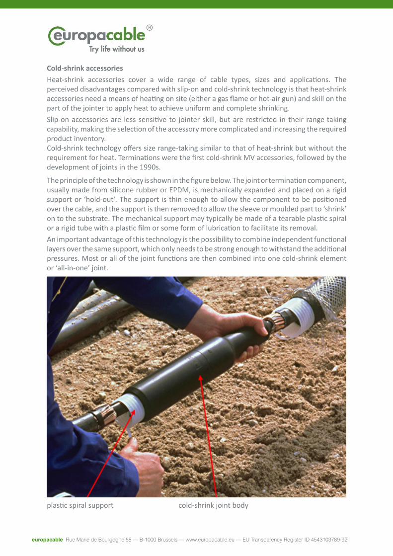
The principle of the technology is shown in the figure below. The joint or termination component, usually made from silicone rubber or EPDM, is mechanically expanded and placed on a rigid support or ‘hold-out’. The support is thin enough to allow the component to be positioned over the cable, and the support is then removed to allow the sleeve or moulded part to ‘shrink’ on to the substrate. The mechanical support may typically be made of a tearable plastic spiral or a rigid tube with a plastic film or some form of lubrication to facilitate its removal.An important advantage of this technology is the possibility to combine independent functional layers over the same support, which only needs to be strong enough to withstand the additional pressures. Most or all of the joint functions are then combined into one cold-shrink element or ‘all-in-one’ joint.
plastic spiral support cold-shrink joint body
europacable Rue Marie de Bourgogne 58 — B-1000 Brussels — www.europacable.eu — EU Transparency Register ID 4543103789-92
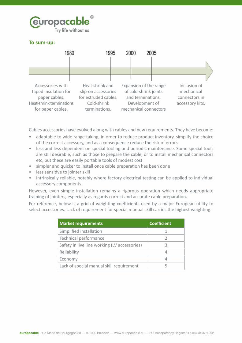
To sum-up:
Cables accessories have evolved along with cables and new requirements. They have become:• adaptable to wide range-taking, in order to reduce product inventory, simplify the choice
of the correct accessory, and as a consequence reduce the risk of errors• less and less dependent on special tooling and periodic maintenance. Some special tools
are still desirable, such as those to prepare the cable, or to install mechanical connectors etc, but these are easily portable tools of modest cost
• simpler and quicker to install once cable preparation has been done• less sensitive to jointer skill• intrinsically reliable, notably where factory electrical testing can be applied to individual
accessory componentsHowever, even simple installation remains a rigorous operation which needs appropriate training of jointers, especially as regards correct and accurate cable preparation.For reference, below is a grid of weighting coefficients used by a major European utility to select accessories. Lack of requirement for special manual skill carries the highest weighting.
Market requirements Coefficient
Simplified installation 1Technical performance 2Safety in live line working (LV accessories) 3Reliability 4Economy 4Lack of special manual skill requirement 5
Accessories with taped insulation for
paper cables.Heat-shrink terminations
for paper cables.
Heat-shrink and slip-on accessories
for extruded cables.Cold-shrink
terminations.
Expansion of the range of cold-shrink joints and terminations.Development of
mechanical connectors
Inclusion of mechanical
connectors in accessory kits.

europacable Rue Marie de Bourgogne 58 — B-1000 Brussels — www.europacable.eu — EU Transparency Register ID 4543103789-92
Conclusions
Cable accessories have been developed and adapted through successive technological steps to accommodate the evolution of cables and networks.
This adaptation has gone along with the evolution of customer needs requiring higher reliability with simpler quicker installation, less material inventory and greater care of the environment.
Thanks to the versatility and maturity of modern accessory technologies and lengthy successful field experience, MV cable accessories are now:• Easy to select because each product may fit a wide range of cable sizes (range-taking) and
design variations• Easier to manage with range-taking accessories and reduced inventory• Easier to install, because even though the cable preparation remains a rigorous operation,
the installation of the accessory itself is simplified• Providing a continuity of electrical, mechanical and thermal performance consistent with
the cables on which they are installed• Reliable, with proven service records• Installed without need for special tooling and the accompanying maintenance and
calibration requirements• Free of products harmful to health such as bitumen and some resin constituents
Nevertheless, it is an unfortunate fact that a large proportion of network failures are associated with accessory faults resulting from poor cable preparation or incorrectly installed accessory components.With the demand for ever-increasing network reliability it is essential that the installation of MV accessories should always be in the hands of trained jointers who are skilled in cable preparation and familiar with the specific accessory technologies.
© 2016 Europacable Services Ltd, Great Britain - All rights reservedPhoto credits: Nexans, Prysmian, TE Connectivity