Cabinet Unit Heater Options Booklet
44
SCVO-12 2/20 Cabinet Unit Heater Options Booklet
Transcript of Cabinet Unit Heater Options Booklet

SCVO-12
2/20
Cabinet Unit Heater Options Booklet
2
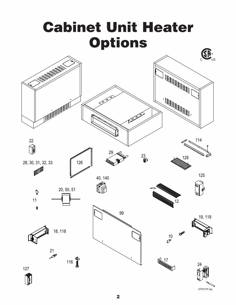
Cabinet Unit HeaterOptions
2329
127
21
11
28, 30, 31, 32, 33
116
18, 118
20, 50, 51
22
126
10
17
12
24
19, 119
125
114
129
CAT00170F.dwg
40, 140
99

3
TABLE OF CONTENTS
OPTION NUMBER PAGE NUMBER LABEL PLACEMENT INFORMATION 4Factory Installed10 LIMITED ACCESS FASTENERS - FRONT PANEL 511 LIMITED ACCESS FASTERERS - ACCESS DOORS 6 12 EXTRUDED ALUMINIUM GRILLE - INLET / OUTLET 713 DECORATOR COLOR 817 LOUVERED INLET GRILLE - FLOOR UNITS 918 25% MANUAL OUTSIDE AIR DAMPER 1019 25% MOTORIZED OUTSIDE AIR DAMPER 1120 HIGH STATIC MOTOR 1221 PLUG-IN MOTOR 1322 MOTOR STARTER 1423 SERVICE SWITCH - DPST 1524 RETURN AIR TEMPERATURE CONTROL 1626 RIGHT HAND COIL CONNECTION 1727 SPECIAL COLOR 1828 INSULATED EXTERNAL CABINET 1929 HIGH CAPACITY TWO ROW COIL 2030 FOIL FACED INSULATION - FRONT PANEL 2131 FOIL FACED INSULATION - EXTERNAL CABINET 2232 CLOSED CELL INSULATION - FRONT PANEL 2333 CLOSED CELL INSULATION - EXTERNAL CABINET 2440 24 VAC 40VA TRANSFORMER 2550 ECM MOTOR PACKAGE 2651 HIGH STATIC ECM MOTOR PACKAGE 2799 14-GAUGE FRONT PANEL 28
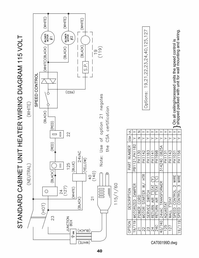
Field Installed113 TOUCH UP PAINT - SEE PRICE SHEET 114 DUCT COLLAR KITS 29116 LEVELING LEGS FOR FLOOR UNITS 30118 25% MANUAL OUTSIDE AIR DAMPER 31119 25% MOTORIZED OUTSIDE AIR DAMPER 32125 AQUASTAT CONTROLLED FAN, FROM RETURN WATER 33126A WALL SEAL KITS - FLOOR UNITS 34126B WALL SEAL KITS - WALL & CEILING UNITS 35 WALL SEAL KITS - INSTRUCTIONS 36127 LINE VOLTAGE ROOM (WALL) THERMOSTAT 37129 EXTRA FILTER 38140 24VAC 40VA TRANSFORMER 39 WIRING DIAGRAM - STANDARD 115 VOLT 40
MODELS, ARRANGEMENTS AND SIZES ARE DESIGNATED AS FOLLOWS:
EXAMPLE
RC - 1190 - 08
MODEL ARRANGEMENT SIZE

4
MAN. MOTOR STARTER
DAMPER
Wiring diagram is located on blower housingaccessed through the front panel, not shown.
WARNING: RISK OF ELECTRIC SHOCK. CAN CAUSE INJURY ORDEATH: DISCONNECT ALL REMOTE ELECTRIC POWER SUPPLIESBEFORE SERVICING; USE COPPER SUPPLY WIRES.
AVERTISSEMENT, RISQUE DE CHOCS ÉLECTRIQUES. PEUT CAUSERDES BLESSURES ET MÊME ENTRAÎNER LA MORT. COUPER LESSOURCES D'ALIMENTATNION A DISTANCE AVANT LE DÉPANNAGE;UTILSER DES FILS D'ALIMENTATION EN CUIVRE.
REPLACE ONLY WITH FILTER MODEL #PC1297-AND SECURE WITH COTTER PINS OR EQUIVALENT.
(PA1245)
(PA1114)
INLET AIR TEMP
POWER
or Here on some units
Located on Piping Connection Side
Fittings must be held securelyfrom turning when connectingto the system. Otherwise da-mage to the heating elementmay result, and will void war-ranty.
CAUTION
(PA1088)
(PA1244)260 NORTH ELM STREET, WESTFIELD, MA 01085
MESTEK, INC.
MOD. NO. SERIAL NO.OUTPUT BTU/HR ELECTRICALHOTWATER 115V/60 AMPS
STEAM MOTOR A: HP FLA
CFM MOTOR B: HP FLAMIN. CIRCUIT AMPACITY: AMPSMAX. FUSE AND CIRCUIT BREAKER SIZE: 15 AMPSMAX. 50 PSI STEAM.
CSA LR85613
CABINET UNIT HEATER
When "Option 21" is used
"USE OF A PLUG INMOTOR CONNECTION
VOIDS CSA
(PA1312)CERTIFICATION"
(PA1115, PA1116,PA1117, PA1803)
Name Plate
CAT00172C.dwg
Cabinet Unit HeaterLabel Placement
(PA1147)
5
Tamper Resistant Screw (PA1084)
Standard Screw (PA1109)
Retainer
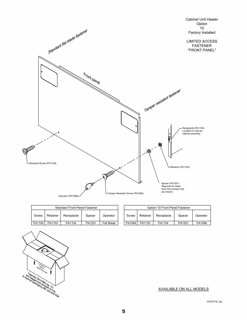
Standard Front Panel Fastener
PA1103PA1109
Screw
Operator (PA1086)
SpacerReceptacle
PA1104
Operator
PA1201 Flat Blade
Retainer (PA1103)
AVAILABLE ON ALL MODELS
flush front panels onlyRequired for lower
PA1201
Spacer
Option 10 Front Panel Fastener
Retainer
PA1084
Screw
PA1103
Receptacle
PA1104
(as shown)
Spacer (PA1201)
PA1086
Operator
Receptacle (PA1104)Located on internalcabinet assembly
Cabinet Unit HeaterOption
10Factory Installed
LIMITED ACCESSFASTENER
"FRONT PANEL"
CAT00173C. dwg

6
Spacer
Standard Access Door Fastener
Stud
PA2037
Retainer
PA1103 PA2038
Access door (MH4099)
Toppanel
Hinge
1/4 turn stud
Retainer
Receptacle (PA1107)
NOT AVAILABLE ON CEILING ORRECESSED CEILING MODELS
PA2038
Spacer
Option 11 Access Door Fastener
PA2042Phillips
Operator
PA1103
RetainerStud Operator
PA1086
Cabinet Unit HeaterOption
11Factory Installed
LIMITED ACCESSFASTENER
"ACCESS DOORS"
CAT00174C.dwg
Access door(MH4099)
Frontpanel
HingeReceptacle(PA1107)
Retainer
1/4 turn stud
Spacer
PA2036 PA1108 None NonePA1085Phillips PA1108 PA1086Front
Panel
TopFront
Panel
Top
Front door assembly
Top door assembly
7
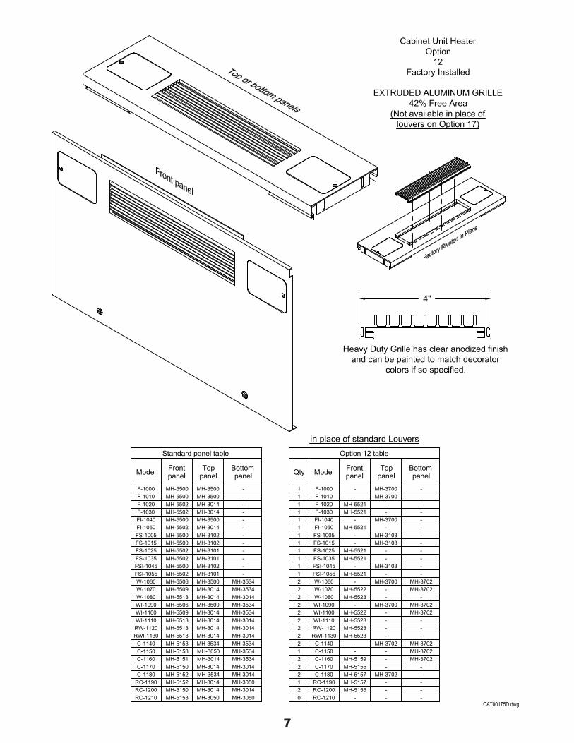
Heavy Duty Grille has clear anodized finishand can be painted to match decorator
colors if so specified.
W-1060 MH-5506 MH-3500 MH-3534MH-3014MH-3014MH-3500MH-3014MH-3014MH-3014MH-3014MH-3534
MH-3534MH-3534
MH-3014MH-3014
MH-3014
MH-3050MH-3014MH-5150RC-1200
RC-1210 MH-5153
RWI-1130C-1140C-1150C-1160C-1170C-1180
RC-1190
W-1070W-1080WI-1090WI-1100WI-1110RW-1120
MH-5513MH-5153MH-5153MH-5151MH-5150MH-5152MH-5152
MH-5509MH-5513MH-5506MH-5509MH-5513MH-5513
MH-3014MH-3050
MH-3534MH-3014MH-3534MH-3534MH-3014MH-3014MH-3014MH-3534
MH-3050MH-3014
MH-3014MH-3534
MH-3050
Toppanel
MH-3102MH-3102MH-3101MH-3101MH-3102MH-3101
Standard panel table
F-1000F-1010F-1020F-1030FI-1040FI-1050
Model
MH-5500MH-5500MH-5502MH-5502MH-5500MH-5502
Frontpanel
Bottompanel
--
-
--
-
Bottom
2 MH-3702MH-3700W-1060 -
MH-5155
MH-5523
MH-5159MH-5155MH-5157MH-5157
MH-5522MH-5523
MH-5522MH-5523MH-5523
2 RC-1200RC-12100 -
W-1080WI-1090WI-1100
RWI-1130
WI-1110RW-1120
C-1140C-1150C-1160C-1170C-1180
RC-1190
W-1070
2
22
12
21
2
22
2
22
--
-
--- -
-MH-3702
--
MH-3702-
-
MH-3700
--
-
--
-MH-3702
-
MH-3702
-
-
MH-3702
MH-3702MH-3702
MH-3702
--
-
In place of standard LouversOption 12 table
MH-5521MH-5521
MH-5521
Frontpanel
F-1000F-1010F-1020F-1030FI-1040FI-1050
Model
1
11
1
11
-
--
panel
MH-3700MH-3700
MH-3700-
--
Top
--
-
--
-
panel
Cabinet Unit HeaterOption
12Factory Installed
EXTRUDED ALUMINUM GRILLE42% Free Area
(Not available in place oflouvers on Option 17)
4"
---
--
-MH-3103
MH-3103
MH-3103
-
-
-MH-5521MH-5521
MH-5521-
--FS-1005
FS-1015FS-1025FS-1035FSI-1045FSI-1055
1
11
111
MH-3500MH-3500MH-3014MH-3014MH-3500MH-3014
MH-5500MH-5502MH-5502MH-5500MH-5502
MH-5500
---
--
-FS-1005FS-1015FS-1025FS-1035FSI-1045FSI-1055
CAT00175D.dwg
Qty
8
We do offer other than the standard ho-hum.
A Decorator Color may be selected from our optional Color Chart. A prime coat of neutral eggshell bakedpowder is standard unless otherwise specified. This may be the final finish or it may be painted in the field ifnecessary.
Cabinet Unit HeaterOption
13Factory Painted
DECORATOR COLOR
See Current ColorChart For Selections
CAT00176A.dwg

9
Option 17
Recommended for use with Options 18, 19, 118, and 119 if used with F or FS units.18 gauge steel, baked powder finish.
14
04
100806
12
0203
Size
MH-4140-14MH-4140-12MH-4140-10MH-4140-08MH-4140-06MH-4140-04MH-4140-03
Part NumberMH-4140-02
Standard on "FI" & FSI ModelsOptional on "F" & FS Models
4" H x 19-51/64" Long4" H x 27-51/64" Long4" H x 31-51/64" Long4" H x 43-51/64" Long4" H x 45-51/64" Long4" H x 50-51/64" Long4" H x 57-51/64" Long4" H x 69-51/64" Long
Dimensions
Cabinet Unit HeaterOption
17Factory Installed
LOUVERED INLET GRILLEFOR
FLOOR MOUNTED UNITS
CAT00177E.DWG

10
Installed on unit(s) at the factory.
Option 17 (louvered inlet grille) is recommended for use withthis option, see Option 17 .
25% manual outside air damper - Outside air intake can be adjusted from 0 to 25%. Control is by manualquadrant. Option 18 or 19 must be ordered with models F-1010, F-1030, FS-1015 and FS-1035. Forfloor units only.
Operator (PB1127)
Inlet screen (MH-2055-(size))
Part No.
MH-4300-02MH-4300-02MH-4300-03
MH-4300-01MH-4300-01MH-4300-01MH-4300-02
MH-4300-03
Option 18
14
03
08
1210
0604
Size02
"A"
18-11/16"
8-3/16"
12-11/16"
18-11/16"12-11/16"
12-11/16"8-3/16"
"A"8-3/16"
Cabinet Unit HeaterOption
18Factory Installed
25% MANUAL OUTSIDEAIR DAMPER
Damper assembly (MH-4300-(size))"B"
4"
"B"
16-5/8"16-5/8"10-5/8"10-5/8"10-5/8"6-1/8"6-1/8"6-1/8"
CAT00178D.dwg

11

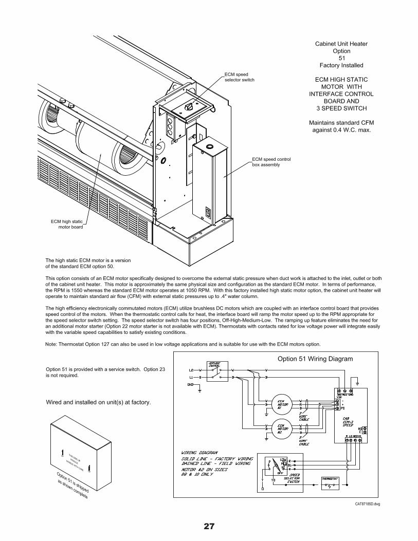
12
This option consists of a motor specified to overcome the external static pressure when duct work is attached to theinlet or outlet of the Cabinet Unit Heater. This motor is approximately the same physical size and configuration as thestandard one; therefore, they are physically interchangeable. In terms of performance it is rated at 1/11 HP at 1550RPM.
With this high static motor installed, the Cabinet Unit Heaters are able to maintain standard airflow with external staticpressure up to 0.4" water column.
Standard motors
04
10
1412
0806
0203
Size
PA1620, PA1621PA1620, PA1621
Part No.
PA1621
PA1621PA1621
PA1621
PA1620PA1620
1
1 EA1 EA
22
1
11
Qty. Qty.
1 EA1 EA
Option 20 motors
PC1320 Single/Double
Part No.
PC1320 Single/DoublePC1320 DoublePC1320 Double
PC1320 SinglePC1320 SinglePC1320 DoublePC1320 Double
1 1.24
22
1
2.482.482.48
1.242.48
11 1.24
1.24
Amps
Double shafted shown
Cabinet Unit HeaterOption
20Factory Installed
HIGH STATIC MOTOR1/11 HP, 1550 RPM 115/1/60 PSC
Maintains standard CFMagainst 0.4" W.C. max.
CAT00180B.dwg
13
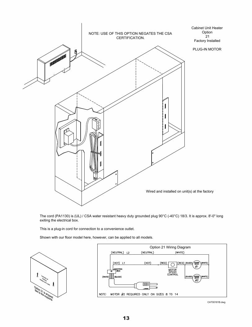
The cord (PA1130) is (UL) / CSA water resistant heavy duty grounded plug 90°C (-40°C) 18/3. It is approx. 8'-0" longexiting the electrical box.
This is a plug-in cord for connection to a convenience outlet.
Shown with our floor model here, however, can be applied to all models.
NOTE: USE OF THIS OPTION NEGATES THE CSACERTIFICATION.
Option 21 Wiring Diagram
Cabinet Unit HeaterOption
21Factory Installed
PLUG-IN MOTOR
Wired and installed on unit(s) at the factory
CAT00181B.dwg
14
Thermaloverload
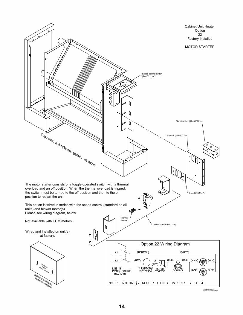
The motor starter consists of a toggle operated switch with a thermaloverload and an off position. When the thermal overload is tripped,the switch must be turned to the off position and then to the onposition to restart the unit.
This option is wired in series with the speed control (standard on allunits) and blower motor(s).Please see wiring diagram, below.
Wired and installed on unit(s)at factory.
Option 22 Wiring Diagram
Motor starter (PA1142)
Label (PA1147)
Bracket (MH-2033)
Electrical box (42400302)
Cabinet Unit HeaterOption
22Factory Installed
MOTOR STARTER
Speed control switch(PA1031) ref.
CAT00182C.dwg
Not available with ECM motors.

15

16

17
Speed control switch (PA1031)not shown, is on the left handside with all other electrical(s).
Coil will be factory mounted with piping connection on right hand side of unit. Electricalconnection and speed control device will be factory wired and installed on left handside of unit(s).
Cabinet Unit HeaterOption
26Factory Installed
RIGHT HAND COILCONNECTION
CAT00185A.dwg

18
Option 27 Special Color Procedure
A minimum of two (2) or more samples, preferably on the material to be used by the factory (steel, aluminum, etc.)must be provided (submitted in advance of an order) to the factory. If possible, the paint manufacturer andmanufacturers part number should also accompany the samples. If this is not possible, a chip from a color chart maybe provided.The factory will then select a paint manufacturer to formulate the match. Two (2) matched samples will be returned, forapproval.The factory will not produce product until one of the color samples is returned with a written approval.
Alternatives to the standard color offerings.
A Special Color Selection can be added to the job specification by either the architect or the owner. Due to the largenumber of colors and paint products available today, it is necessary to go through a submittal and approval processprior to a commitment.
Please contact our sales staff for your inquiries.
Cabinet Unit HeaterOption
27Factory Painted
SPECIAL COLORConsult Factory
CAT00186C.dwg

19
The floor unit is shown here, however this will represent typicallocation of insulation material.
Insulation is 1-1/2 pound density, 1/2" thick fiberglass, neoprenecoated one (1) side and adhered to each panel prior to assembly.
Cabinet Unit HeaterOption
28Factory Installed
INSULATED EXTERNAL CABINET
Insulation (2191001A)typical
CAT00187D.dwg

20
This is a Hot Water coil designed to provide increased capacity when the required load exceeds that of the standardcoil for a given size. Fins are double depth and there are two rows of tubes.
The durable mechanically bonded copper/aluminum coil presents the best of today's hydronic technology. Providing 12fins per inch with 1/2" nominal diameter tubes, the ultimate in BTU capacity is provided without sacrificing noise,vibration or amp draw.
All units are designed so that field modifications can be made to reverse the coil position if required.
Standard coils 2 row coils
1214
Size
0810
06
0304
02
MH-1003-08
MH-1003-14MH-1003-12MH-1003-10
MH-1003-06MH-1003-04MH-1003-03MH-1003-02Part Number
1214
10
Size
03
0608
04
02 MH-1002-02MH-1002-03MH-1002-04MH-1002-06MH-1002-08MH-1002-10
Part Number
MH-1002-14MH-1002-12
Cabinet Unit HeaterOption
29Factory Installed
HIGH CAPACITYTWO ROW COIL
"WATER ONLY"
High capacity
Coil
1-1/4" Nom. O.D.
1-1/4" Nom. O.D.
CAT00188C.dwg
21
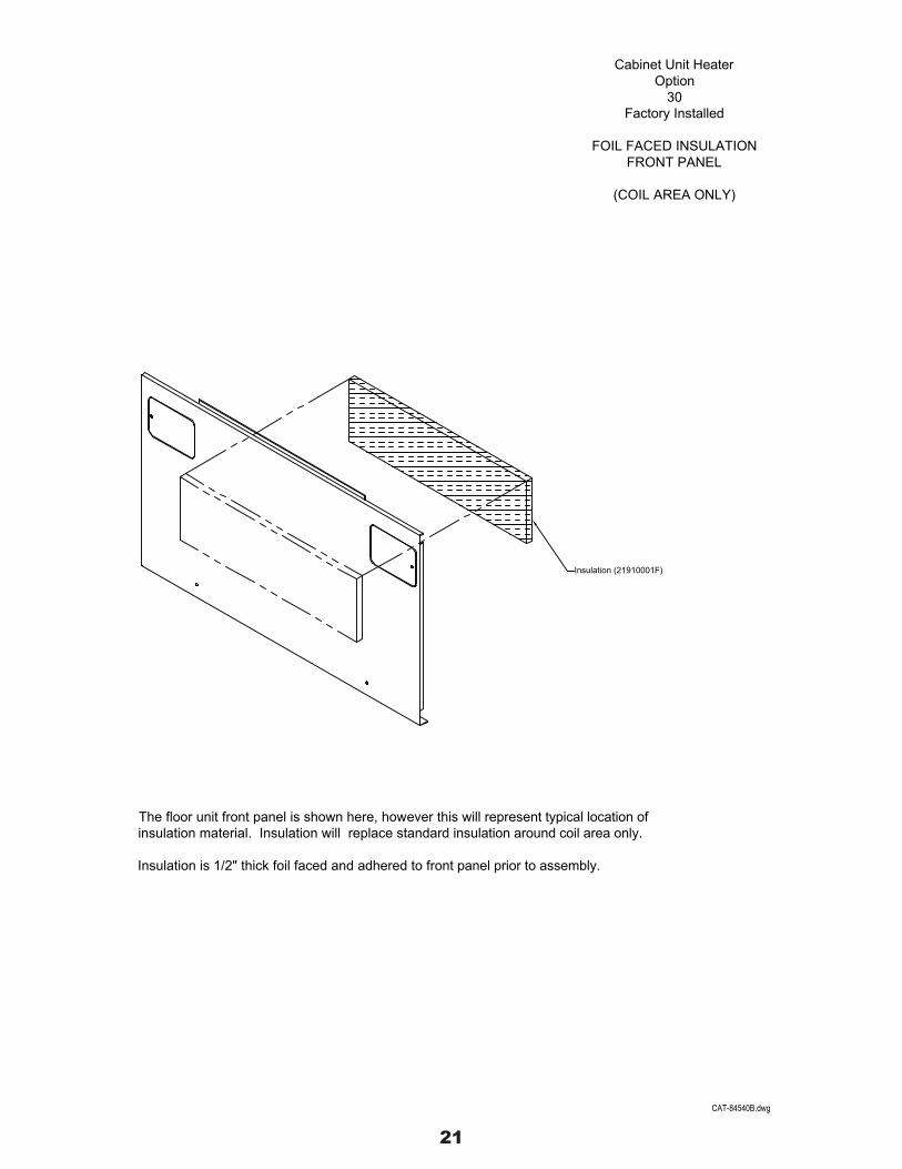
The floor unit front panel is shown here, however this will represent typical location ofinsulation material. Insulation will replace standard insulation around coil area only.
Insulation is 1/2" thick foil faced and adhered to front panel prior to assembly.
Cabinet Unit HeaterOption
30Factory Installed
FOIL FACED INSULATIONFRONT PANEL
(COIL AREA ONLY)
Insulation (21910001F)
CAT-84540B.dwg
22
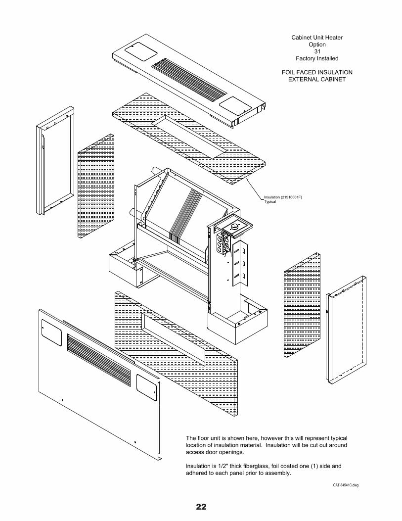
The floor unit is shown here, however this will represent typicallocation of insulation material. Insulation will be cut out aroundaccess door openings.
Insulation is 1/2" thick fiberglass, foil coated one (1) side andadhered to each panel prior to assembly.
Cabinet Unit HeaterOption
31Factory Installed
FOIL FACED INSULATIONEXTERNAL CABINET
Insulation (21910001F)Typical
CAT-84541C.dwg
23
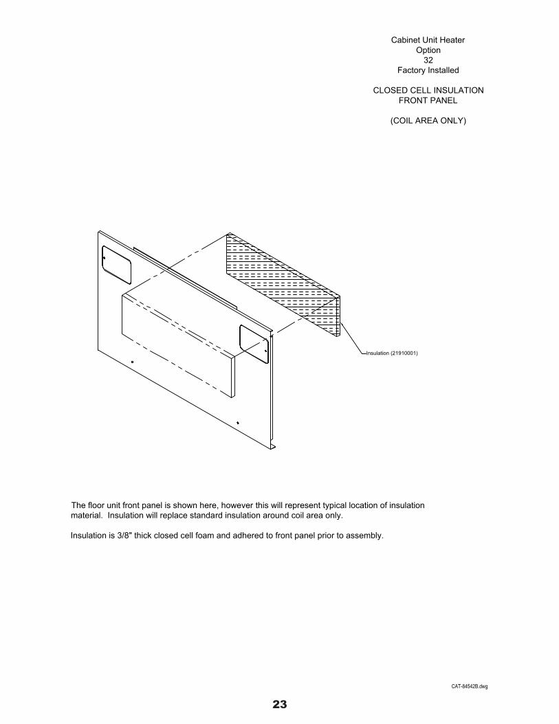
The floor unit front panel is shown here, however this will represent typical location of insulationmaterial. Insulation will replace standard insulation around coil area only.
Insulation is 3/8" thick closed cell foam and adhered to front panel prior to assembly.
Cabinet Unit HeaterOption
32Factory Installed
CLOSED CELL INSULATIONFRONT PANEL
(COIL AREA ONLY)
CAT-84542B.dwg
Insulation (21910001)
24
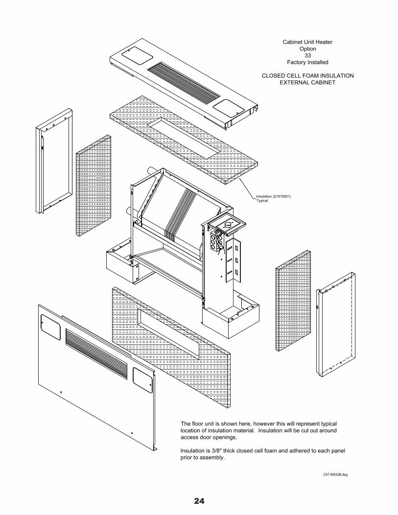
The floor unit is shown here, however this will represent typicallocation of insulation material. Insulation will be cut out aroundaccess door openings.
Insulation is 3/8" thick closed cell foam and adhered to each panelprior to assembly.
Cabinet Unit HeaterOption
33Factory Installed
CLOSED CELL FOAM INSULATIONEXTERNAL CABINET
Insulation (21910001)Typical
CAT-84543B.dwg

25
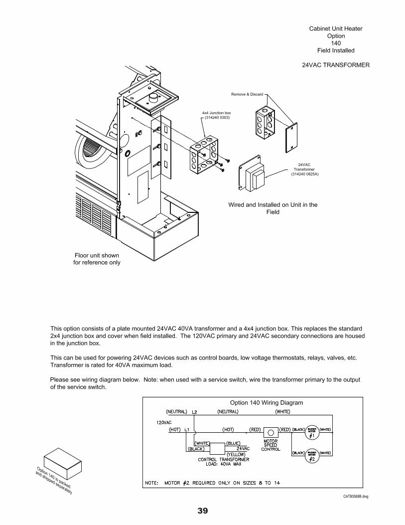
This option consists of a plate mounted 24VAC 40VA transformer and a 4x4 junction box. The 120VAC primary and24VAC secondary connections are housed in the junction box.
This can be used for powering 24VAC devices such as control boards, low voltage thermostats, relays, valves, etc.Transformer is rated for 40VA maximum load.
Please see wiring diagram below.
Option 40 Wiring Diagram
Cabinet Unit HeaterOption
40Factory Installed
24VAC TRANSFORMER
Wired and installed on unit at factory
CAT80567A.dwg
Floor unit shownfor reference only
24VACTransformer
(314240 0825A)
4x4 Junction box (314240 0303)
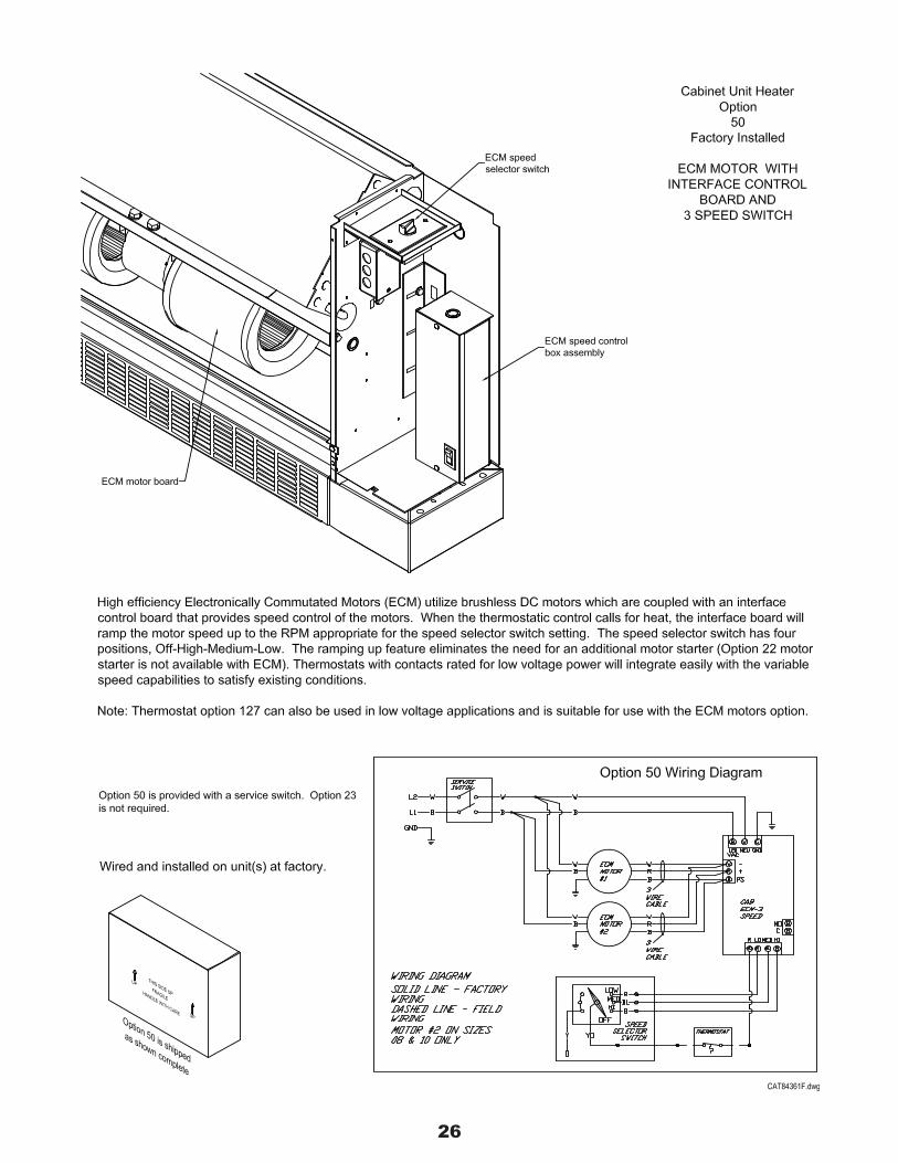
26
27

28
The floor unit front panel is shown for reference. Access doors and inlet/outlet locationswill vary by model.
Cabinet Unit HeaterOption
99Factory Installed
14 GAUGE FRONT PANEL
CAT-84544D.dwg

29
1214
Unit
100806040302
Cabinet Unit HeaterOption
114Field Installed
DUCT COLLAR KIT
For Rectangular OpeningIn Top and Bottom Panels
Kit contents
Runner End(2 each) (2 each)
MH-3058.02 MH-3056MH-3056MH-3056MH-3056MH-3056MH-3056MH-3056MH-3056
MH-3058.03MH-3058.04MH-3058.06MH-3058.08MH-3058.10MH-3058.12MH-3058.14
To install:Unpack cabinet unit heater. Place unit upright, align duct end/runners inplace, drill and secure.
02
Size
060403
121008
"A"
18"26"30"42"
49"56"68"
44"
4-1/8" x 18-1/8"should be
Mating duct I.D.
4-1/8" x 26-1/8"4-1/8" x 30-1/8"4-1/8" x 42-1/8"4-1/8" x 44-1/8"4-1/8" x 49-1/8"4-1/8" x 56-1/8"4-1/8" x 68-1/8"
It is recommended that the louver area is cut out prior to duct collar installation.
Duct collars are intended to be used with louvers cut away as shown.
14
(2) Duct End (MH-3056)1"
1"
Screws
4"
(2) Duct Runner (MH-3058-xx)
"A"
5/8"
1"
CAT00189C.dwg
Size
Note:Duct collar kits are standard on models C-1150, RC-1190 and RC-1210.

30
View shown with pedestal removed from unit
To install:Unpack cabinet unit heater. Lay unit flat on its back, and follow the above instructions.
(4) Leveler screw (PA1102)
Insert and adjust to suit leveling conditions
2
1
Pedestal
(4) U-Snap nut(PA1101)
Pedestal
Cabinet Unit HeaterOption
116Field Installed
LEVELING LEGSFOR
FLOOR MOUNTED UNITS
Pedestal (MH-4083)
CAT00190D.dwg

31
Operator (PB1127)
25% manual outside air damper - outside air intake can be adjusted from 0 to 25%.Control is by manual quadrant. For use on floor units only.
4-7/16"
Inlet screen (MH-2055-(Size))
Damper assembly (MH-4300-(Size))
Option 118
18-11/16"
8-3/16"12-11/16"
8-3/16"8-3/16"
12-11/16"18-11/16"
12-11/16"
14
Size
03
08
1210
0604
02
MH-4300-03
MH-4300-02MH-4300-01MH-4300-01MH-4300-01
MH-4300-03MH-4300-02MH-4300-02
Part Number
21-15/16"
11-7/16"15-15/16"
11-7/16"11-7/16"
15-15/16"21-15/16"
15-15/16"
"A" "B"
Cabinet Unit HeaterOption
118Field Installed
25% MANUAL OUTSIDEAIR DAMPER
"B"
"A"
(4) 5/16" Holes
3-15/16" Max.
CAT00191C.dwg

32

33

34
RecommendedOpening25-1/4"
Option 126A
1" Min. Recess
F-1000, F-1010and
FI-1040
1 7/8" Max. Recess
2 1/4"
1/4" Holes
OPT. 126A-02
Kit Number
OPT. 126A-03OPT. 126A-04OPT. 126A-06OPT. 126A-08OPT. 126A-10OPT. 126A-12OPT. 126A-1414
Size
02
06081012
0304
1 3/8"
9/16" 1"
Left Riser
Screw
Right Riser
F-1020, F-1030and
FI-1050
"A"
35-1/2"43-1/2"47-1/2"59-1/2"61-1/2"66-1/2"73-1/2"85-1/2"
25"
9 1/8" Max. Recess
1" Min. Recess
9 1/2"
RecommendedOpening
"A"
Cabinet Unit HeaterOption126A
Field Installed
WALL SEAL KIT"FLOOR UNITS"
Runner
CAT00194B.dwg
35
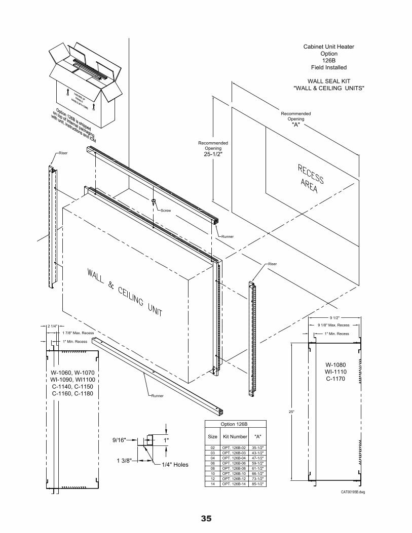
RecommendedOpening25-1/2"
Option 126B
1/4" Holes
W-1060, W-1070WI-1090, WI1100C-1140, C-1150C-1160, C-1180
1" Min. Recess
1 7/8" Max. Recess
2 1/4"
OPT. 126B-02
Kit Number
OPT. 126B-03OPT. 126B-04OPT. 126B-06OPT. 126B-08OPT. 126B-10OPT. 126B-12OPT. 126B-1414
Size
02
06081012
0304
Runner
Riser
Screw
1 3/8"
9/16" 1"
Riser
"A"
35-1/2"43-1/2"47-1/2"59-1/2"61-1/2"66-1/2"73-1/2"85-1/2"
25"
1" Min. Recess
W-1080WI-1110C-1170
9 1/8" Max. Recess
9 1/2"
RecommendedOpening
"A"
Cabinet Unit HeaterOption126B
Field Installed
WALL SEAL KIT"WALL & CEILING UNITS"
Runner
CAT00195B.dwg
36
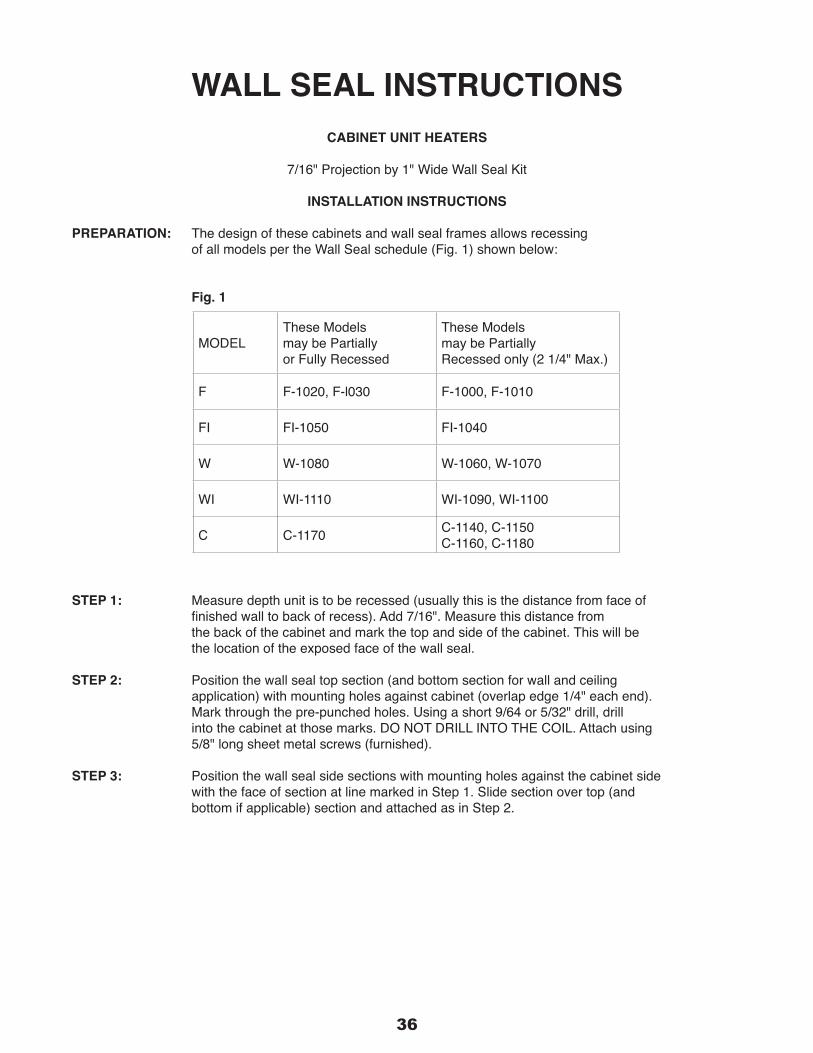
WALL SEAL INSTRUCTIONSCABINET UNIT HEATERS
7/16" Projection by 1" Wide Wall Seal Kit
INSTALLATION INSTRUCTIONS
PREPARATION: The design of these cabinets and wall seal frames allows recessing of all models per the Wall Seal schedule (Fig. 1) shown below:
Fig. 1
STEP 1: Measure depth unit is to be recessed (usually this is the distance from face of finishedwalltobackofrecess).Add7/16".Measurethisdistancefrom thebackofthecabinetandmarkthetopandsideofthecabinet.Thiswillbe the location of the exposed face of the wall seal.
STEP 2: Position the wall seal top section (and bottom section for wall and ceiling application) with mounting holes against cabinet (overlap edge 1/4" each end). Markthroughthepre-punchedholes.Usingashort9/64or5/32"drill,drill intothecabinetatthosemarks.DONOTDRILLINTOTHECOIL.Attachusing 5/8" long sheet metal screws (furnished).
STEP 3: Position the wall seal side sections with mounting holes against the cabinet side withthefaceofsectionatlinemarkedinStep1.Slidesectionovertop(and bottom if applicable) section and attached as in Step 2.
MODELThese Models may be Partially or Fully Recessed
These Models may be Partially Recessed only (2 1/4" Max.)
F F-1020, F-l030 F-1000, F-1010
FI FI-1050 FI-1040
W W-1080 W-1060, W-1070
WI WI-1110 WI-1090, WI-1100
C C-1170 C-1140, C-1150C-1160, C-1180

37

38
PA1089 (2) 3/32" Cotter pinsHolds filter in placeIf required, must be ordered separately
Permanent washable "EVK" type filterAluminum frame, expanded aluminum pad, UL CLASS 2.06 SP @ 350 FPM
Standard Filters
15/32"H x 8-11/16"D x 69-3/4"L15/32"H x 8-11/16"D x 57-3/4"L15/32"H x 8-11/16"D x 50-3/4"L15/32"H x 8-11/16"D x 45-3/4"L15/32"H x 8-11/16"D x 43-3/4"L15/32"H x 8-11/16"D x 31-3/4"L15/32"H x 8-11/16"D x 27-3/4"L15/32"H x 8-11/16"D x 19-3/4"L
129 PC1297-1010
129129
PC1297-14PC1297-1212
14
129
129129129129
OPTION
PC1297-08PC1297-06PC1297-04PC1297-03PC1297-02Part Number
02
0806
0304
SIZE Filter Dimensions
Cabinet Unit HeaterOption
129Field Installed
EXTRA FILTER
(Shipped Separately)
CAT00198A.dwg
39
40

41

42

43

©CopyrightMestek,Inc.