Cabinet Installation
81
7/30/2019 Cabinet Installation http://slidepdf.com/reader/full/cabinet-installation 1/81 Cabinet Installation dn99109459 Issue 5-0 en # Nokia Corporation Nokia Proprietary and Confidential 1 (81) 468956A.505_NOLS Nokia UltraSite EDGE Base Station User Manual
Transcript of Cabinet Installation

7/30/2019 Cabinet Installation
http://slidepdf.com/reader/full/cabinet-installation 1/81
Cabinet Installation
dn99109459Issue 5-0 en
# Nokia CorporationNokia Proprietary and Confidential
1 (81)
468956A.505_NOLS
Nokia UltraSite EDGE Base Station User Manual

7/30/2019 Cabinet Installation
http://slidepdf.com/reader/full/cabinet-installation 2/81
The information in this document is subject to change without notice and describes only theproduct defined in the introduction of this documentation. This document is intended for the useof Nokia's customers only for the purposes of the agreement under which the document issubmitted, and no part of it may be reproduced or transmitted in any form or means without theprior written permission of Nokia. The document has been prepared to be used by professionaland properly trained personnel, and the customer assumes full responsibility when using it.Nokia welcomes customer comments as part of the process of continuous development andimprovement of the documentation.
The information or statements given in this document concerning the suitability, capacity, or performance of the mentioned hardware or software products cannot be considered binding butshall be defined in the agreement made between Nokia and the customer. However, Nokia hasmade all reasonable efforts to ensure that the instructions contained in the document areadequate and free of material errors and omissions. Nokia will, if necessary, explain issueswhich may not be covered by the document.
Nokia's liability for any errors in the document is limited to the documentary correction of errors.NOKIA WILL NOT BE RESPONSIBLE IN ANY EVENT FOR ERRORS IN THIS DOCUMENTOR FOR ANY DAMAGES, INCIDENTAL OR CONSEQUENTIAL (INCLUDING MONETARYLOSSES), that might arise from the use of this document or the information in it.
This document and the product it describes are considered protected by copyright according tothe applicable laws.
NOKIA logo is a registered trademark of Nokia Corporation.
Other product names mentioned in this document may be trademarks of their respectivecompanies, and they are mentioned for identification purposes only.
Copyright © Nokia Corporation 2002. All rights reserved.
Hereby, Nokia Corporation declares that this Nokia UltraSite
EDGE Base Station is in compliance with the essential
requirements and other relevant provisions of Directive :1999/5/EC.
The product is marked with the CE marking and Notified Body
number according to the Directive 1999/5/EC.
This equipment has been tested and found to comply with the limits for a Class B
digital device, pursuant to part 15 of the FCC Rules. These limits are designed to
provide reasonable protection against harmful interference in a residential installation.
This equipment generates, uses and can radiate radio frequency energy and, if not
installed and used in accordance with the instructions, may cause harmful interference
to radio communications. However, there is no guarantee that interference will not
occur in a particular installation.
Changes or modifications not expressly approved by the party responsible for
compliance could void the user s authority to operate the equipment.
The term IC: before the radio certification number only signifies that Industry Canada
technical specifications were met.
0523
2 (81) # Nokia CorporationNokia Proprietary and Confidential
dn99109459Issue 5-0 en
Cabinet Installation
7/30/2019 Cabinet Installation
http://slidepdf.com/reader/full/cabinet-installation 3/81
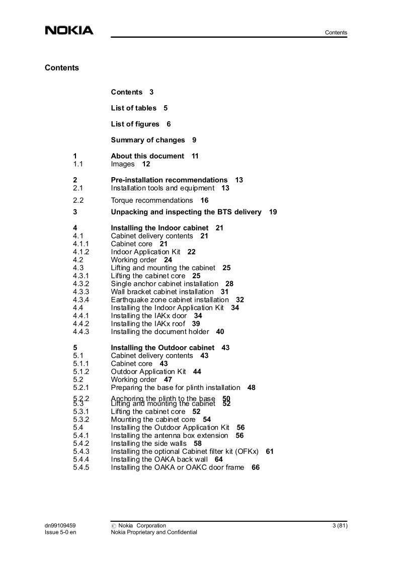
Contents
Contents 3
List of tables 5
List of figures 6
Summary of changes 9
1 About this document 111.1 Images 12
2 Pre-installation recommendations 132.1 Installation tools and equipment 13
2.2 Torque recommendations 16
3 Unpacking and inspecting the BTS delivery 19
4 Installing the Indoor cabinet 214.1 Cabinet delivery contents 214.1.1 Cabinet core 214.1.2 Indoor Application Kit 224.2 Working order 244.3 Lifting and mounting the cabinet 254.3.1 Lifting the cabinet core 254.3.2 Single anchor cabinet installation 284.3.3 Wall bracket cabinet installation 314.3.4 Earthquake zone cabinet installation 324.4 Installing the Indoor Application Kit 344.4.1 Installing the IAKx door 344.4.2 Installing the IAKx roof 394.4.3 Installing the document holder 40
5 Installing the Outdoor cabinet 435.1 Cabinet delivery contents 435.1.1 Cabinet core 435.1.2 Outdoor Application Kit 445.2 Working order 475.2.1 Preparing the base for plinth installation 48
5.2.2 Anchoring the plinth to the base 505.3 Lifting and mounting the cabinet 525.3.1 Lifting the cabinet core 525.3.2 Mounting the cabinet core 545.4 Installing the Outdoor Application Kit 565.4.1 Installing the antenna box extension 565.4.2 Installing the side walls 585.4.3 Installing the optional Cabinet filter kit (OFKx) 615.4.4 Installing the OAKA back wall 645.4.5 Installing the OAKA or OAKC door frame 66
dn99109459Issue 5-0 en
# Nokia CorporationNokia Proprietary and Confidential
3 (81)
Contents

7/30/2019 Cabinet Installation
http://slidepdf.com/reader/full/cabinet-installation 4/81
5.4.6 Installing the OAKA or OAKC roof 695.4.7 Installing the OAKA or OAKC door 725.4.8 Installing a door lock 785.4.9 Installing the door switch 79
5.4.10 Installing the document holder 81
4 (81) # Nokia CorporationNokia Proprietary and Confidential
dn99109459Issue 5-0 en
Cabinet Installation

7/30/2019 Cabinet Installation
http://slidepdf.com/reader/full/cabinet-installation 5/81
List of tables
Table 1. Standard installation tools 13
Table 2. Electronic instruments 15
Table 3. Installation tools for external transmission cables 16
Table 4. Cabinet installation torque recommendations 16
dn99109459Issue 5-0 en
# Nokia CorporationNokia Proprietary and Confidential
5 (81)
List of tables
7/30/2019 Cabinet Installation
http://slidepdf.com/reader/full/cabinet-installation 6/81
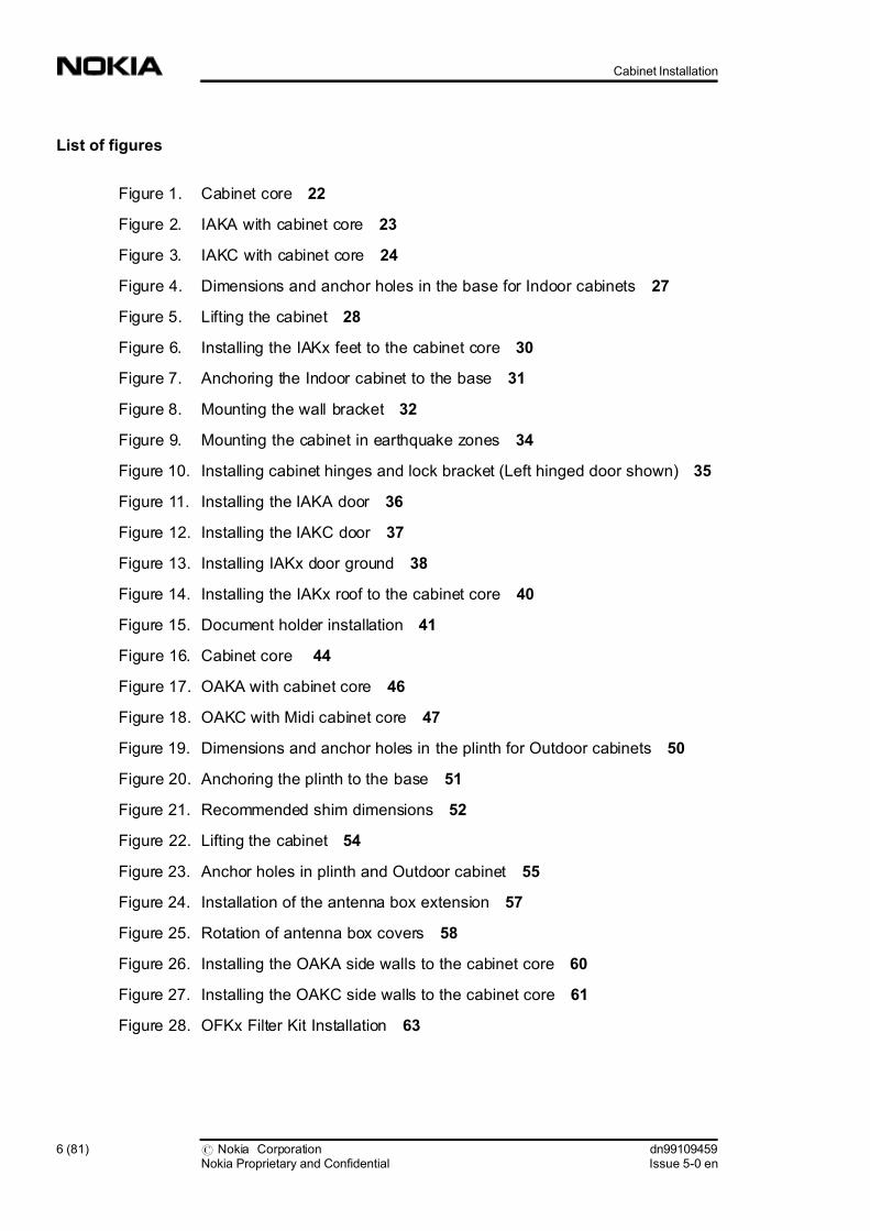
List of figures
Figure 1. Cabinet core 22
Figure 2. IAKA with cabinet core 23
Figure 3. IAKC with cabinet core 24
Figure 4. Dimensions and anchor holes in the base for Indoor cabinets 27
Figure 5. Lifting the cabinet 28
Figure 6. Installing the IAKx feet to the cabinet core 30
Figure 7. Anchoring the Indoor cabinet to the base 31
Figure 8. Mounting the wall bracket 32
Figure 9. Mounting the cabinet in earthquake zones 34
Figure 10. Installing cabinet hinges and lock bracket (Left hinged door shown) 35
Figure 11. Installing the IAKA door 36
Figure 12. Installing the IAKC door 37
Figure 13. Installing IAKx door ground 38
Figure 14. Installing the IAKx roof to the cabinet core 40
Figure 15. Document holder installation 41
Figure 16. Cabinet core 44
Figure 17. OAKA with cabinet core 46
Figure 18. OAKC with Midi cabinet core 47
Figure 19. Dimensions and anchor holes in the plinth for Outdoor cabinets 50
Figure 20. Anchoring the plinth to the base 51
Figure 21. Recommended shim dimensions 52
Figure 22. Lifting the cabinet 54
Figure 23. Anchor holes in plinth and Outdoor cabinet 55
Figure 24. Installation of the antenna box extension 57
Figure 25. Rotation of antenna box covers 58
Figure 26. Installing the OAKA side walls to the cabinet core 60
Figure 27. Installing the OAKC side walls to the cabinet core 61
Figure 28. OFKx Filter Kit Installation 63
6 (81) # Nokia CorporationNokia Proprietary and Confidential
dn99109459Issue 5-0 en
Cabinet Installation

7/30/2019 Cabinet Installation
http://slidepdf.com/reader/full/cabinet-installation 7/81
Figure 29. Installing the OAKA back wall to the cabinet core 65
Figure 30. Installing the OAKC back wall to the cabinet core 66
Figure 31. Installing the OAKA door frame to the cabinet core 68Figure 32. Installing the OAKC door frame to the cabinet core 69
Figure 33. Installing the roof support assembly to the cabinet core) 71
Figure 34. Attaching the roof to the roof support assembly 72
Figure 35. Configuration of OAKA door hinge pins and door stay 74
Figure 36. Installing the OAKA door to the cabinet 75
Figure 37. Installing the OAKC door to the cabinet 76
Figure 38. OAK door grounding 77
Figure 39. Installing the door lock mechanism 79
Figure 40. Door switch installation 80
Figure 41. Document holder installation 81
dn99109459Issue 5-0 en
# Nokia CorporationNokia Proprietary and Confidential
7 (81)
List of figures

7/30/2019 Cabinet Installation
http://slidepdf.com/reader/full/cabinet-installation 8/81
8 (81) # Nokia CorporationNokia Proprietary and Confidential
dn99109459Issue 5-0 en
Cabinet Installation

7/30/2019 Cabinet Installation
http://slidepdf.com/reader/full/cabinet-installation 9/81
Summary of changes
Summary of changes
First Release, 30 June 2000
Second Release, 12 January 2001
Third Release, 01 August 2001
Fourth Release, 31 December 2001
Fifth Release, 26 April 2002
dn99109459Issue 5-0 en
# Nokia CorporationNokia Proprietary and Confidential
9 (81)
Summary of changes

7/30/2019 Cabinet Installation
http://slidepdf.com/reader/full/cabinet-installation 10/81
10 (81) # Nokia CorporationNokia Proprietary and Confidential
dn99109459Issue 5-0 en
Cabinet Installation

7/30/2019 Cabinet Installation
http://slidepdf.com/reader/full/cabinet-installation 11/81
1 About this document
Purpose
The Cabinet Installation document describes how to install Nokia UltraSite
EDGE Base Station (BTS) Indoor, Outdoor, Midi Indoor, and Midi Outdoor
cabinets.
Contents
This document contains the following information:
. Chapter 2 Pre-installation recommendations
. Chapter 3 Unpacking and inspecting the BTS delivery
. Chapter 4 Installing the Indoor cabinet
. Chapter 5 Installing the Outdoor cabinet
Readership
The following personnel should be familiar with this document before they start
site planning or installation:
. installation planners
. installation and commissioning personnel
. operation and maintenance (O&M) personnel
Prerequisites
Nokia requires that personnel who perform installation, commissioning, and
maintenance tasks have basic knowledge of base station systems and equipment.
Pay careful attention to all Warnings and Cautions in this document.
dn99109459Issue 5-0 en
# Nokia CorporationNokia Proprietary and Confidential
11 (81)
About this document

7/30/2019 Cabinet Installation
http://slidepdf.com/reader/full/cabinet-installation 12/81
1.1 Images
Readers should note that all images in this document are typical in nature and are
for general reference only.
For hardware, the versions depicted may differ from the latest version of
equipment.
For software, any version numbers shown in any of the windows/screens/dialog
boxes may not be the same as the actual software that is to be installed. It is
important to remember that the procedure steps must be followed, as these will
give advice on the correct software to be installed and the correct text that will be
displayed in each window/screen/dialog box.
12 (81) # Nokia CorporationNokia Proprietary and Confidential
dn99109459Issue 5-0 en
Cabinet Installation

7/30/2019 Cabinet Installation
http://slidepdf.com/reader/full/cabinet-installation 13/81
2 Pre-installation recommendations
This chapter describes the equipment recommendations and the torque
recommendations for installation of Nokia UltraSite EDGE BTS. Detailed
instructions for installing the cabinet are provided in subsequent chapters of this
document.
2.1 Installation tools and equipment
This section describes the equipment Nokia recommends for installing the
components and cables of the cabinet and plug-in units.
Table 1 lists the European and US specifications for the standard tools and
equipment you need during installation of Nokia UltraSite EDGE BTS.
Note
Nokia does not include installation tools and equipment in the BTS delivery
package.
Table 1. Standard installation tools
European U.S.
Antistatic wrist strap and cable
Automatic puncher to mark hole locations
Cable cutters, 2.5 to 50 mm2 8 electricians cable cutters
Cable stripper, 0.25 and 0.4 wire Standard electricians wire strippers
dn99109459Issue 5-0 en
# Nokia CorporationNokia Proprietary and Confidential
13 (81)
Pre-installation recommendations

7/30/2019 Cabinet Installation
http://slidepdf.com/reader/full/cabinet-installation 14/81
Table 1. Standard installation tools (cont.)
European U.S.
Cable stripper, 2.5 to 50 mm2 Cable stripping knife
Cable ties for securing cables
Calliper square, 160 mm Generic calliper - 6 square, adjustable
Coaxial cable stripper for 75 & transmission cables
Concrete drill bit, 12 mm Concrete drill bit, 1/2
Crimping tool for grounding cable shoes
Drill with screwdriver bit set Drill, 1/4 drive
1/4 hex drive
Drill bit set, 1 to 13 mm
Extension cord
Flashlight, pocket lamp, or torch Flashlight
Hammer
Hammer drill
Hexagon keys, 8 mm
Indelible marker
Insulated wrench for installing batteries
Insulated side cutters
Ladder
Level Basic level
Lifting eye bolts, four pieces, M12 (not included)
Pliers:
. Insulated needle nose pliers, 115 mm
. Insulated flat nose pliers, 210 mm
. Multigrip pliers, 250 mm
Pliers:
. Insulated needle nose pliers, 4.5"
. Insulated standard pliers, 8"
. Vise-grips, 10"
Right angle
14 (81) # Nokia CorporationNokia Proprietary and Confidential
dn99109459Issue 5-0 en
Cabinet Installation

7/30/2019 Cabinet Installation
http://slidepdf.com/reader/full/cabinet-installation 15/81
Table 1. Standard installation tools (cont.)
European U.S.
RJ modular plug crimp tool
Safety glasses
Scissors
Screwdriver sets:
. Flathead
. Phillips
. TORX, T10 through T25
SMA torque wrench 1 Nm (0.74 ft lb) and 0.45 Nm (0.33 ft lb)
Socket wrench (10 to 19 mm) and exten-
sion socket
Socket sets, metric (1/4 and 3/8) drive
and extension socket
Tape measure, 5 m Tape measure, 16 ft
Torque 38 driver 6.7 - 101.7 Nm (15 - 75 ft lb)
Utility knife
Wrench, adjustable 8
Wrench set, metric combo, 7 to 19 mm
Table 2 lists the electronic instruments you need to install units.
Table 2. Electronic instruments
Instrument Required Capabilities
Frequency counter
Example: HP 53132A
. Digital readout with accuracy better
than 0.1 Hz. Capable of at least 14 MHz clock
signal with needed accuracy
Power meter
Example: Gigatronic 8652A
. Digital readout with accuracy to at
least one decimal place
. Capable of TX measurement of 50W/
+47 dBm or less
. Optional: TX in and TX out (external
terminator/attenuator) for trouble-
shooting
dn99109459Issue 5-0 en
# Nokia CorporationNokia Proprietary and Confidential
15 (81)
Pre-installation recommendations

7/30/2019 Cabinet Installation
http://slidepdf.com/reader/full/cabinet-installation 16/81
Table 3 lists the tools you need to install external transmission cables.
Table 3. Installation tools for external transmission cables
Tool Cable
Radiall crimping tool R282.281.000 and posi-
tioner R282.967.034
Radiall connectors BQ (100/120 &)
Rosenberger crimping tool:
. 11W150-000
. 11W150-7R9 for cable TWC-124-1A
. 11W150-7W2 for cable Belden 8132
Rosenberger connectors BQ (100/
120 &)
Crimping tool:
. AGK 2353 with crimp inserts for cables RG
179 B/U, RG 187 A/U: AGK 2709
. AKG 2365 with crimp inserts for cables RG
179 B/U, RG 187 A/U: AGK 2727
SMB/BT43 (75 &) with cable RG
179 B/U, RG 187 A/U
2.2 Torque recommendations
This section describes the Nokia recommended torque values for variousfasteners used in Nokia UltraSite EDGE BTS.
Note
These are basic torque values. Any exceptions to these values are provided in the
installation procedures.
Table4
lists the torque measurements Nokia recommends for installing thecabinet units. All torque values assume a lubricated bolt or fastener.
Table 4. Cabinet installation torque recommendations
Bolt/screw type DIN Size Torque
Plastic connector finger screws 0.2 - 0.3 Nm
16 (81) # Nokia CorporationNokia Proprietary and Confidential
dn99109459Issue 5-0 en
Cabinet Installation

7/30/2019 Cabinet Installation
http://slidepdf.com/reader/full/cabinet-installation 17/81
Table 4. Cabinet installation torque recommendations (cont.)
Bolt/screw type DIN Size Torque
(0.15 - 0.22 ft lb)
Slotted head, phillips head or
Torx head screw
M3 0.7 - 1.0 Nm
(0.52 - 0.74 ft lb)
Slotted head, phillips head or
Torx head screw
M4 1.2 - 1.6 Nm
(0.88 - 1.18 ft lb)
Slotted head, phillips head or
Torx head screw
M5 2.0 - 2.6 Nm
(1.47 - 1.92 ft lb)
Hexagon socket head screw 933-A2 M6 4.2 - 5.5 Nm
(3.1 - 4.05 ft lb)
Nut 934-A2 M6 4.2 - 5.5 Nm
(3.1 - 4.05 ft lb)
Hexagon socket head screw 912-A2 M8 8.0 - 10.0 Nm
(5.9 - 7.37 ft lb)
3/8 hexagon head bolt 933-A2 M10 24 Nm
(17.69 ft lb)
Lifting eye bolt (not included) 580 M12 39 Nm
(28.74 ft lb)
dn99109459Issue 5-0 en
# Nokia CorporationNokia Proprietary and Confidential
17 (81)
Pre-installation recommendations

7/30/2019 Cabinet Installation
http://slidepdf.com/reader/full/cabinet-installation 18/81
18 (81) # Nokia CorporationNokia Proprietary and Confidential
dn99109459Issue 5-0 en
Cabinet Installation

7/30/2019 Cabinet Installation
http://slidepdf.com/reader/full/cabinet-installation 19/81
3 Unpacking and inspecting the BTS
delivery
This chapter describes how you unpack and inspect the contents of the BTS
cabinet delivery package.
Warning
Nokia UltraSite EDGE BTS has many sharp edges. Exercise caution during
installation.
Warning
Empty CRMA and CRMC cabinet cores weigh 79 kg (155 lb) and 52 kg (115
lb) respectivly. Nokia recommends that a lifting device be used when moving
a cabinet core.
To unpack and inspect the delivery package:
1. Lift the core assembly from the delivery package.
2. Remove the cardboard and plastic wrap from the assembly.
3. Remove the desiccant packs, if present.
4. Inspect the assembly for visible damage.
5. Unpack the cabinet application kit and inspect the contents for visible
damage.
6. Use the packing list to check the completeness of the delivery.
dn99109459Issue 5-0 en
# Nokia CorporationNokia Proprietary and Confidential
19 (81)
Unpacking and inspecting the BTS delivery

7/30/2019 Cabinet Installation
http://slidepdf.com/reader/full/cabinet-installation 20/81
Note
If any contents of the delivery are damaged or missing, immediately report these
findings to your local Nokia representative.
7. Store the packing list in the site folder.
8. Recycle the packing material.
20 (81) # Nokia CorporationNokia Proprietary and Confidential
dn99109459Issue 5-0 en
Cabinet Installation

7/30/2019 Cabinet Installation
http://slidepdf.com/reader/full/cabinet-installation 21/81
4 Installing the Indoor cabinet
This chapter describes how to install Nokia UltraSite EDGE BTS Indoor (CRMA
with IAKA) and Midi Indoor (CRMC with IAKC) cabinets.
4.1 Cabinet delivery contents
The cabinet delivery for the Indoor and Midi Indoor BTS includes the following:
. cabinet core (CRMA or CRMC)
. indoor application kit (IAKA or IAKC)
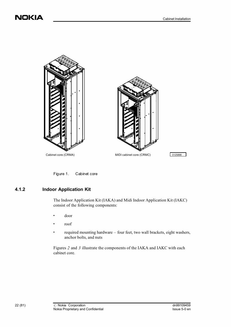
4.1.1 Cabinet core
The cabinet core houses the units and Temperature Control System. The cabinet
application kits define the type of cabinet, Indoor or Outdoor.
Figure 1 illustrates the core of the Indoor and Midi Indoor cabinets.
dn99109459Issue 5-0 en
# Nokia CorporationNokia Proprietary and Confidential
21 (81)
Installing the Indoor cabinet
7/30/2019 Cabinet Installation
http://slidepdf.com/reader/full/cabinet-installation 22/81
Figure 1. Cabinet core
4.1.2 Indoor Application Kit
The Indoor Application Kit (IAKA) and Midi Indoor Application Kit (IAKC)
consist of the following components:
. door
. roof
. required mounting hardware four feet, two wall brackets, eight washers,
anchor bolts, and nuts
Figures 2 and 3 illustrate the components of the IAKA and IAKC with each
cabinet core.
0125888MIDI cabinet core (CRMC)Cabinet core (CRMA)
22 (81) # Nokia CorporationNokia Proprietary and Confidential
dn99109459Issue 5-0 en
Cabinet Installation

7/30/2019 Cabinet Installation
http://slidepdf.com/reader/full/cabinet-installation 23/81
Figure 2. IAKA with cabinet core
Cabinet core(CRMA)
(4 places) 99614855
(2 places)
KEY:1. Feet
2. Roof
3. Door
4. Wall brackets
1
2
4
3
dn99109459Issue 5-0 en
# Nokia CorporationNokia Proprietary and Confidential
23 (81)
Installing the Indoor cabinet
7/30/2019 Cabinet Installation
http://slidepdf.com/reader/full/cabinet-installation 24/81
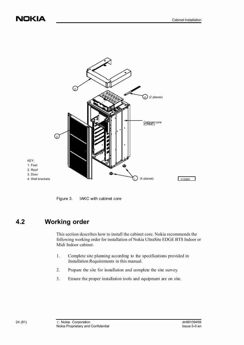
Figure 3. IAKC with cabinet core
4.2 Working order
This section describes how to install the cabinet core. Nokia recommends the
following working order for installation of Nokia UltraSite EDGE BTS Indoor or
Midi Indoor cabinet.
1. Complete site planning according to the specifications provided in
Installation Requirements in this manual.
2. Prepare the site for installation and complete the site survey.
3. Ensure the proper installation tools and equipment are on site.
Cabinet core(CRMC)
(4 places) 0125891
(2 places)
KEY:
1. Feet
2. Roof
3. Door
4. Wall brackets 1
2
4
3
24 (81) # Nokia CorporationNokia Proprietary and Confidential
dn99109459Issue 5-0 en
Cabinet Installation

7/30/2019 Cabinet Installation
http://slidepdf.com/reader/full/cabinet-installation 25/81
4. Unpack and inspect the contents of the BTS delivery for visible damage.
For more information, see Chapter 3, Unpacking and inspecting the BTS
delivery .
5. Prepare the base for the cabinet.
6. Mount the cabinet to the base using one of the three mounting options. See
the section Lifting and mounting the cabinet .
7. Inspect the cabinet to ensure it is level.
8. Install the Indoor Application Kit (IAKx) to the cabinet core. See the
section, Installing the Indoor Application Kit .
4.3 Lifting and mounting the cabinet
This section describes how to lift and mount an empty cabinet core.
For indoor installations, the cabinet core mounts to a base surface using one of
the following anchoring procedures:
. Mount the cabinet to the base using a single anchor bolt and four levelling
feet.
Note
In US installations, Una Struts may be used in place of levelling feet.
. Where a support wall is within 210 mm (4.5 in.), mount the cabinet using
two wall brackets and four levelling feet.
. Where dictated by earthquake risk, mount the cabinet to the base using four
anchor bolts.
4.3.1 Lifting the cabinet core
If you use a mechanical lifting device, Nokia recommends you use lifting eye
bolts. Use all four lifting points on the cabinet top. The lifting points support the
weight of an empty cabinet core.
dn99109459Issue 5-0 en
# Nokia CorporationNokia Proprietary and Confidential
25 (81)
Installing the Indoor cabinet

7/30/2019 Cabinet Installation
http://slidepdf.com/reader/full/cabinet-installation 26/81
Warning
Empty CRMA and CRMC cabinet cores weigh 79 kg (155 lb) and 52 kg (115
lb) respectivly. Nokia recommends that a lifting device be used when moving
a cabinet core.
Warning
When lifting or positioning the cabinet, avoid tilting the cabinet forward.
Internal components, such as cables, may fall out.
Caution
If the installation site is in an area affected by seismic activity, follow the
earthquake mounting instructions.
Note
The recommended M12 (1/2 in.) lifting eye bolts and anchor bolts are not
included in the delivery package.
Figure 4 illustrates the dimensions and anchor holes for installation of the Indoor
cabinet.
26 (81) # Nokia CorporationNokia Proprietary and Confidential
dn99109459Issue 5-0 en
Cabinet Installation

7/30/2019 Cabinet Installation
http://slidepdf.com/reader/full/cabinet-installation 27/81
Figure 4. Dimensions and anchor holes in the base for Indoor cabinets
Figure 5 illustrates how to lift the cabinet core using the lifting eye bolts.
To lift the cabinet core using lifting eye bolts:
1. Screw one M12 (1/2 in.) lifting eye bolt into each corner of the cabinet
core.
2. Attach the lifting ropes to the lifting eye bolts as shown in Figure5
.
3. Carefully lift the cabinet core.
4. Position the cabinet in place.
5. Bolt the cabinet into position.
6. Remove the ropes and lifting eye bolts.
00159475
305(12.0)
145
(5.7)179
(7.0)
52 (2.0)minimum
179.5
(7.1)
179.5
(7.1)
300
(11.8)
179.5
(7.1)
179.5
(7.1)
300
(11.8)
457
(18.0)
150
(5.9)
71.5
(2.8)
Hole for plastic
foot (4 places)
148
(5.8)
600
(23.6)
620
(24.4)570
(22.4)
Front
Cabinet 1 Cabinet 2
Facility wallBack stop
X
XeXe Xe
XeXe Xe
X X
X X X
X X X
NOTES:
1. Xe - Location of earthquake anchor holes
2. X - Location of additional anchor holes
3. Dimensions: mm (in.)
dn99109459Issue 5-0 en
# Nokia CorporationNokia Proprietary and Confidential
27 (81)
Installing the Indoor cabinet

7/30/2019 Cabinet Installation
http://slidepdf.com/reader/full/cabinet-installation 28/81
Figure 5. Lifting the cabinet
4.3.2 Single anchor cabinet installation
Warning
When drilling, wear the necessary protective gear, such as gloves and safety
glasses.
99627293
Lifting eye bolts
(4 places)
Minimum
800 (31.5)
To lifting device
NOTE: Dimensions: mm (in.)
28 (81) # Nokia CorporationNokia Proprietary and Confidential
dn99109459Issue 5-0 en
Cabinet Installation

7/30/2019 Cabinet Installation
http://slidepdf.com/reader/full/cabinet-installation 29/81
Note
The diameter of the anchor hole in the cabinet floor is 13 mm (0.5 in.). The
anchor bolt size is M10 or M12.
Note
You can mark anchor hole locations through the floor with the cabinet in place or
using a cardboard template. You can make the template by tracing the outline of
the cabinet bottom including the anchor holes.
Figure 6 illustrates how to install the cabinet feet.
Figure 7 illustrates how to anchor the cabinet to the base.
To prepare the base:
1. Screw the four cabinet feet into the threaded holes on the bottom of the
cabinet core.
2. Refer to the lifting procedure in the previous section to lift the cabinet into place.
3. Position the cabinet backstop outward.
4. Mark the base through one of the two centre bolt holes.
5. Move the cabinet off the base if necessary.
6. Drill the anchor hole as marked on the base, and clear any debris.
dn99109459Issue 5-0 en
# Nokia CorporationNokia Proprietary and Confidential
29 (81)
Installing the Indoor cabinet

7/30/2019 Cabinet Installation
http://slidepdf.com/reader/full/cabinet-installation 30/81
Figure 6. Installing the IAKx feet to the cabinet core
To anchor the cabinet core:
1. Insert and secure the anchor bolt in the anchor hole.
2. Position a nut and 50 mm flat washer on the anchor bolt and turn until it is
approximately the height of the floor of the installed cabinet as shown in
Figure 7 .
3. Lift the cabinet into place over the anchor bolt.
4. Use a level and adjust the cabinet.
5. Install a 30 mm flat washer on the anchor bolt and secure it with a nut.
6. Hold the lower nut under the cabinet floor with an open end wrench while
you tighten the upper nut to 80 Nm (60 ft lb).
00204227
Foot
(four places)
Cabinet core placed horizontally
with front facing upwards
Make sure that back stop
is angled out of the way
Threaded hole
(four places)
30 (81) # Nokia CorporationNokia Proprietary and Confidential
dn99109459Issue 5-0 en
Cabinet Installation

7/30/2019 Cabinet Installation
http://slidepdf.com/reader/full/cabinet-installation 31/81
Figure 7. Anchoring the Indoor cabinet to the base
4.3.3 Wall bracket cabinet installation
Warning
When drilling, wear the necessary protective gear, such as gloves and safety
glasses.
Figure 8 illustrates how to mount the cabinet using wall brackets.
To mount the cabinet with a wall bracket:
1. Screw the four cabinet feet into the threaded holes on the bottom of the
cabinet core.
2. Refer to the lifting procedure in the previous section to lift the cabinet into
place.
3. Use a level and adjust the cabinet feet.
4. Position a support bracket at each top corner of the cabinet, and bend the
bracket so that it fits against the wall and the cabinet corner.
5. Remove the back corner bolts from the cabinet top and replace the bolts
with the wall brackets in place.
00201872
Adjustable
foot
Cabinet
core
Washers
Mounting
base
M10 or M12 nuts
M10 or M12
anchor bolt
dn99109459Issue 5-0 en
# Nokia CorporationNokia Proprietary and Confidential
31 (81)
Installing the Indoor cabinet

7/30/2019 Cabinet Installation
http://slidepdf.com/reader/full/cabinet-installation 32/81
6. Mark the wall and drill holes for anchors (not supplied).
7. Use M6, M8, or M10 screws (not supplied) to attach the brackets to the
wall.
Figure 8. Mounting the wall bracket
4.3.4 Earthquake zone cabinet installation
Warning
When drilling, wear the necessary protective gear, such as gloves and safety
glasses.
Roof
Wall bracket
(two places)
Secure bracket to BTS
using roof mounting bolt
NOTE: Bracket may be used when
wall is between 52 mm and 210 mm
from back of BTS
Secure bracket to
site wallBracket
detail
BTS front00289762
Bend
lines
M10
M8
M6
32 (81) # Nokia CorporationNokia Proprietary and Confidential
dn99109459Issue 5-0 en
Cabinet Installation

7/30/2019 Cabinet Installation
http://slidepdf.com/reader/full/cabinet-installation 33/81
Caution
Uneven bolt installation can damage the cabinet floor.
Note
The diameter of the anchor hole in the cabinet floor is 13 mm (0.5 in.). The
anchor bolt size is M10 to M12.
Note
You can mark anchor hole locations through the floor with the cabinet in place or
using a cardboard template. You can make the template by tracing the outline of
the cabinet bottom including the anchor holes.
Figure 9 illustrates how to mount the cabinet in earthquake zones.
To mount the cabinet in an earthquake zone:
1. Refer to the lifting procedure in the previous section to lift the cabinet into
place to mark anchor hole locations.
2. Mark the base through the four corner bolt holes. See Figure 4 for the bolt
pattern (positions marked Xe).
3. Move the cabinet off the base if necessary.
4. Drill the anchor holes marked on the base and clear any debris.
5. Insert and secure the four anchor bolts in the anchor holes.
6. Lift the cabinet into place and align it over the anchor bolts.
7. On each anchor bolt, install a 30 mm flat washer and secure it with a nut.
8. Tighten the nuts to 80 Nm (60 ft lb).
dn99109459Issue 5-0 en
# Nokia CorporationNokia Proprietary and Confidential
33 (81)
Installing the Indoor cabinet

7/30/2019 Cabinet Installation
http://slidepdf.com/reader/full/cabinet-installation 34/81
Figure 9. Mounting the cabinet in earthquake zones
4.4 Installing the Indoor Application Kit
This section describes how you install the IAKx to the cabinet core. Nokia
recommends the following working order for installing the IAKx.
1. Install the door.
2. Install the roof.
4.4.1 Installing the IAKx door
This section describes how you install the IAKx door. Nokia recommends the
following working order for installing the IAKx door to the cabinet core.
1. Install the door hinges to the cabinet core.
2. Install the optional ILKA lock bracket to the cabinet core.
3. Install the door to the cabinet hinges.
4. Attach the door grounding strap.
Figure 10 illustrates how to install the door hinges to the cabinet core. Nokia
provides the choice of right or left door orientation.
0126996
Bottom of
cabinet core Washer
Mountingbase
M10 or M12 nut
M10 or M12anchor bolt
34 (81) # Nokia CorporationNokia Proprietary and Confidential
dn99109459Issue 5-0 en
Cabinet Installation

7/30/2019 Cabinet Installation
http://slidepdf.com/reader/full/cabinet-installation 35/81
To install the door hinges to the cabinet core:
1. Determine whether the door is left (default) or right opening in accordance
with the site plan.
2. If necessary, remove the hinges attached to the cabinet core, rotate the
hinges 180°, and reinstall them on the opposite side using the two upper
mounting holes of the hinge.
3. Install ILKA Lock bracket on opposite side of upper hinge.
Figure 10. Installing cabinet hinges and lock bracket (Left hinged door shown)
Figures 11 and 12 illustrate hinges mounted on the left side (default).
To install the door to the cabinet core:
1. If necessary, flip the door end-for-end.
2. Lift the door and engage the hinge pins in the sockets on the front of the
cabinet core.
00293867
Left installationof hinge
Right ILKAlock installation
(Installation of lower hinge is identical)
Rotate hinge/lock180 degrees
dn99109459Issue 5-0 en
# Nokia CorporationNokia Proprietary and Confidential
35 (81)
Installing the Indoor cabinet

7/30/2019 Cabinet Installation
http://slidepdf.com/reader/full/cabinet-installation 36/81
tip:
Engage the door in the hinges with the door open at a 90° angle.
Figure 11. Installing the IAKA door
99627375
Cabinet door
Cabinet
Core
Hinge
Hinge
36 (81) # Nokia CorporationNokia Proprietary and Confidential
dn99109459Issue 5-0 en
Cabinet Installation

7/30/2019 Cabinet Installation
http://slidepdf.com/reader/full/cabinet-installation 37/81
Figure 12. Installing the IAKC door
tip:
If the door does not go on the hinges, verify the following:
. The hinges are installed on the cabinet using the top and middle holes.
. The hinges are installed in the correct direction.
Figure 13 illustrates installation of the door grounding strap.
0134652
Cabinet door
Cabinet
Core
Hinge
Hinge
dn99109459Issue 5-0 en
# Nokia CorporationNokia Proprietary and Confidential
37 (81)
Installing the Indoor cabinet

7/30/2019 Cabinet Installation
http://slidepdf.com/reader/full/cabinet-installation 38/81
To attach the door grounding strap:
1. If required, remove the grounding strap from the default (left opening)
position on the door, and install it on the right side of the door.
2. Remove the outer lockwasher and nut from the door ground lug bolt inside
the door.
3. Slide the end of the door grounding strap over the lug bolt.
4. Fasten the strap in place with the lockwasher and nut.
Figure 13. Installing IAKx door ground
tip:
If the door does not close, verify the following:
. The grounding cable is fixed at both ends and is not between the door and
the cabinet.
. The door latch is open.
. The transmission shield is assembled correctly.
00251655
Cabinet door
Grounding
strap
Lug
(two places)
Cabinet ground stud (frontcorner, behind flange)
Door
ground stud
Nut
(4 places)
Lockwasher
(4 places)
Cabinet
Core
38 (81) # Nokia CorporationNokia Proprietary and Confidential
dn99109459Issue 5-0 en
Cabinet Installation

7/30/2019 Cabinet Installation
http://slidepdf.com/reader/full/cabinet-installation 39/81
4.4.2 Installing the IAKx roof
Figure 14 illustrates how to install the roof to the Indoor cabinet core.
To install the roof:
1. Insert four M12 bolts through the holes and loosely screw them into the
cabinet core.
2. Align the four slots at the bottom of the roof with the four holes on the top
of the cabinet core.
3. Slide the roof slots around the four M12 bolts installed in the cabinet andtighten the bolts.
tip:
If the roof does not go onto the core, verify the following:
. The four M12 screws are loosened.
. The cables are not between the antenna box and roof.
dn99109459Issue 5-0 en
# Nokia CorporationNokia Proprietary and Confidential
39 (81)
Installing the Indoor cabinet

7/30/2019 Cabinet Installation
http://slidepdf.com/reader/full/cabinet-installation 40/81
Figure 14. Installing the IAKx roof to the cabinet core
4.4.3 Installing the document holder
The document holder is installed in the lower left corner of the CRMx cabinet for
storage of papers pertaining to that particular cabinet or site.
Note
When a M2xA unit is installed in the bottom slot of the cabinet, the document
holder cannot be installed.
99627351
S
S
S
Roof
Cabinet door Cabinet door
Roof
A
A
AA
NOTE:
S = Bolt location
A = Bolt access
S
40 (81) # Nokia CorporationNokia Proprietary and Confidential
dn99109459Issue 5-0 en
Cabinet Installation

7/30/2019 Cabinet Installation
http://slidepdf.com/reader/full/cabinet-installation 41/81
To install the document holder:
1. Position the document holder in front of the lower left corner of the cabinet
and slide it between the unit mounting supports.
2. Hook the tabs of the document holder into the slots provided in the right
side unit mounting support.
Figure 15. Document holder installation
0151451
Document holder,
removed
Document holder
Cabinet Core
dn99109459Issue 5-0 en
# Nokia CorporationNokia Proprietary and Confidential
41 (81)
Installing the Indoor cabinet

7/30/2019 Cabinet Installation
http://slidepdf.com/reader/full/cabinet-installation 42/81
42 (81) # Nokia CorporationNokia Proprietary and Confidential
dn99109459Issue 5-0 en
Cabinet Installation

7/30/2019 Cabinet Installation
http://slidepdf.com/reader/full/cabinet-installation 43/81
5 Installing the Outdoor cabinet
This chapter describes how to install Nokia UltraSite EDGE BTS Outdoor
(CRMA with OAKA) and Midi Outdoor (CRMC with OAKC) cabinets.
5.1 Cabinet delivery contents
The cabinet delivery for the Outdoor BTS includes the following:
. cabinet core (CRMA or CRMC)
. outdoor application kit (OAKA or OAKC)
. optional cabinet filter kit (OFKA or OFKC)
5.1.1 Cabinet core
The cabinet core houses the units and Temperature Control System. The cabinet
application kits define the type of cabinet, Indoor or Outdoor.
Figure 16 illustrates the core of the Outdoor and Midi cabinets.
dn99109459Issue 5-0 en
# Nokia CorporationNokia Proprietary and Confidential
43 (81)
Installing the Outdoor cabinet

7/30/2019 Cabinet Installation
http://slidepdf.com/reader/full/cabinet-installation 44/81
Figure 16. Cabinet core
5.1.2 Outdoor Application Kit
The Outdoor Application Kit (OAKA or OAKC) consists of the following
components:
. plinth for one cabinet
. antenna box extension assembly (optional with OAKA and not used with
OAKC). back wall
. two side walls
. door frame
. door with a pre-installed Cabinet Cooling fan
. door switch assembly
0125888MIDI cabinet core (CRMC)Cabinet core (CRMA)
44 (81) # Nokia CorporationNokia Proprietary and Confidential
dn99109459Issue 5-0 en
Cabinet Installation
7/30/2019 Cabinet Installation
http://slidepdf.com/reader/full/cabinet-installation 45/81
. roof
. required mounting hardware
You can also install an optional Heater unit (HETA) in the OAKA or OAKC door.See Unit Installation in this manual.
Figures 17 and 18 illustrate the components of the OAKA and OAKC with each
cabinet core.
dn99109459Issue 5-0 en
# Nokia CorporationNokia Proprietary and Confidential
45 (81)
Installing the Outdoor cabinet

7/30/2019 Cabinet Installation
http://slidepdf.com/reader/full/cabinet-installation 46/81
Figure 17. OAKA with cabinet core
99614867
KEY:
1. Back wall
2. Side wall
3. Door frame
4. Plinth
5. Roof
6. Door 7. Door switch assembly
8. Antenna box extension
3
2
1
8
7
4
5
Cabinet core
(CRMA)
6
2
46 (81) # Nokia CorporationNokia Proprietary and Confidential
dn99109459Issue 5-0 en
Cabinet Installation

7/30/2019 Cabinet Installation
http://slidepdf.com/reader/full/cabinet-installation 47/81
Figure 18. OAKC with Midi cabinet core
5.2 Working order
Nokia recommends the following working order for installation of Nokia
UltraSite EDGE BTS Outdoor cabinets.
0125907
KEY:
1. Back wall
2. Side wall
3. Door frame
4. Plinth
5. Roof
6. Door
7. Door switch assembly
3
2
7
4
5
Cabinet core(CRMC)
1
26
dn99109459Issue 5-0 en
# Nokia CorporationNokia Proprietary and Confidential
47 (81)
Installing the Outdoor cabinet

7/30/2019 Cabinet Installation
http://slidepdf.com/reader/full/cabinet-installation 48/81
1. Complete site planning according to the specifications provided in
Installation Requirements in this manual.
2. Prepare the site for installation and complete the site survey.
3. Ensure the proper installation tools and equipment are on site.
4. Unpack and inspect the contents of the BTS delivery for any visible
damage. For more information, see Chapter 3, Unpacking and Inspecting
the BTS delivery .
5. Prepare the base for OAKA or OAKC installation.
6. Lift and mount the cabinet on the plinth.
Note
The side and back walls of the OAKA or OAKC must be installed first when you
install the cabinet in limited space that restricts access to the back or sides of the
cabinet.
7. Install the Outdoor Application Kit (OAKA or OAKC) to the cabinet core.
8. Install the optional Cabinet Filter Kit (OFKA or OFKC) to the side walls, if
required.
5.2.1 Preparing the base for plinth installation
This section describes what is required prior to installation of the BTS cabinet.
Warning
When drilling, wear the necessary protective gear, such as gloves and safety
glasses.
Caution
The plinth weighs approximately 10 kg (22.05 lb). Handle the plinth with care.
48 (81) # Nokia CorporationNokia Proprietary and Confidential
dn99109459Issue 5-0 en
Cabinet Installation

7/30/2019 Cabinet Installation
http://slidepdf.com/reader/full/cabinet-installation 49/81
Figure 19 illustrates the dimensions and anchor holes for installation of the
Outdoor cabinet plinth.
To prepare the base for plinth installation:
1. Ensure the base is strong enough to withstand the weight of the BTS core
and units.
2. Paint the base, if necessary.
3. Position the plinth on the base according to the site plan. If you are
installing more than one cabinet, ensure that there is 18 mm (.71 in.)
clearance between plinths.
4. Mark the base through the four anchor holes of the plinth.
5. Remove the plinth from the base before drilling anchor holes.
6. Drill the anchor holes in the base, and carefully remove any debris.
dn99109459Issue 5-0 en
# Nokia CorporationNokia Proprietary and Confidential
49 (81)
Installing the Outdoor cabinet

7/30/2019 Cabinet Installation
http://slidepdf.com/reader/full/cabinet-installation 50/81
Figure 19. Dimensions and anchor holes in the plinth for Outdoor cabinets
5.2.2 Anchoring the plinth to the base
Figure 20 illustrates how to anchor the plinth to the base.
Figure 21 illustrates the recommended shim dimensions.
To anchor the plinth to the base:
Note
The cabinet delivery does not contain shims or plinth-to-base installation
hardware. To order site-specific materials, contact your local Nokia
representative.
00159463
Front
Plinth of cabinet 1 Plinth of cabinet 2
X XX
X X
752(29.6)
18(0.7)
107(4.2)
575(22.7)
730
(28.7)
126(5.0)
250(9.8)
250(9.8)
519(20.4)
560(22.0)
NOTES:1. X - Location of plinth anchor holes2. Dimensions: mm (in.)
66(2.6)
76(3.0)
620
(24.4)
770
(30.3)
150(5.9)
96(3.8)
50 (81) # Nokia CorporationNokia Proprietary and Confidential
dn99109459Issue 5-0 en
Cabinet Installation

7/30/2019 Cabinet Installation
http://slidepdf.com/reader/full/cabinet-installation 51/81
1. Place the plinth on the base over the anchor holes.
2. Check the plinth for level and install shims if required.
3. Depending on the type of base, do one of the following:
. For a concrete base, install the anchor bolts and secure the plinth to
the base with four washers and nuts.
. For metal mounting frame installation, secure the plinth to the frame
with four M12 (1/2 in.) bolts, eight washers, and four nuts.
4. Tighten the nuts to 80 Nm (60 ft lb).
Figure 20. Anchoring the plinth to the base
99627278
PlinthPlinth
Note
M e ta l
f r a m e
W a s h e r
W a s h e r s
C o n c r e t e
b a s e
NOTE: This dimension not to exceed 27 mm (1.1 in.)
M10 or M12
nut
M10 or M12
nut
M10 or M12
anchor bolt
M10 or M12
bolt
dn99109459Issue 5-0 en
# Nokia CorporationNokia Proprietary and Confidential
51 (81)
Installing the Outdoor cabinet

7/30/2019 Cabinet Installation
http://slidepdf.com/reader/full/cabinet-installation 52/81
Figure 21. Recommended shim dimensions
5.3 Lifting and mounting the cabinet
5.3.1 Lifting the cabinet core
This section describes how to lift an empty cabinet core. If you use a mechanical
lifting device, Nokia recommends you use lifting eye bolts. Use all four lifting
points on the cabinet top. The lifting points support the weight of an empty
cabinet core.
Warning
An empty cabinet core weighs a maximum of 70 kg (155 lb). Nokia
recommends that a lifting device be used when moving the cabinet core.
99627281
30
(1.2)
Slot diameter 13(0.5)
NOTE: Dimensions mm (in.)
75(3.0)
60
(2.4)
150
(5.9)
52 (81) # Nokia CorporationNokia Proprietary and Confidential
dn99109459Issue 5-0 en
Cabinet Installation

7/30/2019 Cabinet Installation
http://slidepdf.com/reader/full/cabinet-installation 53/81
Warning
When lifting or positioning the cabinet, avoid tilting the cabinet forward.
Internal components, such as cables, may fall out.
Note
The recommended M12 (1/2 in.) lifting eye bolts and anchor bolts are not
included in the delivery package.
Figure 22 illustrates how to lift the cabinet core using lifting eye bolts.
To lift the cabinet core using lifting eye bolts:
1. Screw one M12 (1/2 in.) lifting eye bolt into each corner of the cabinet
core.
2. Attach the lifting ropes to the lifting eye bolts.
3. Carefully lift the cabinet core.
4. Position the cabinet in place.
5. Bolt the cabinet into position.
6. Remove the ropes and lifting eye bolts.
dn99109459Issue 5-0 en
# Nokia CorporationNokia Proprietary and Confidential
53 (81)
Installing the Outdoor cabinet

7/30/2019 Cabinet Installation
http://slidepdf.com/reader/full/cabinet-installation 54/81
Figure 22. Lifting the cabinet
5.3.2 Mounting the cabinet core
Figure 23 illustrates how to install the cabinet core to the plinth.
To install the cabinet core to the plinth:
1. Refer to the lifting procedure in the previous section to lift the cabinet into place.
2. Secure the cabinet core with the M10 (50 mm) mounting bolts included in
the OAKA or OAKC delivery.
99627293
Lifting eye bolts
(4 places)
Minimum
800 (31.5)
To lifting device
NOTE: Dimensions: mm (in.)
54 (81) # Nokia CorporationNokia Proprietary and Confidential
dn99109459Issue 5-0 en
Cabinet Installation

7/30/2019 Cabinet Installation
http://slidepdf.com/reader/full/cabinet-installation 55/81
Figure 23. Anchor holes in plinth and Outdoor cabinet
tip:
If the cabinet does not fit on the plinth, verify the following:
. The plinth is not backwards.
. Nothing is between the cabinet bottom and the plinth.
99627312
Cabinet
Core
Plinth
(Secured to base/slab)
dn99109459Issue 5-0 en
# Nokia CorporationNokia Proprietary and Confidential
55 (81)
Installing the Outdoor cabinet

7/30/2019 Cabinet Installation
http://slidepdf.com/reader/full/cabinet-installation 56/81
. The plinths mounting holes are open.
. The backstop is oriented to the rear.
5.4 Installing the Outdoor Application Kit
This section describes how you install the OAKA or OAKC to the cabinet core.
Nokia recommends the following working order for installing the OAKA or
OAKC:
1. antenna box extension (optional with OAKA and not used with OAKC)
2. side walls
3. back wall
4. door frame
5. roof
6. door
7. door switch
Note
In tight quarters, install the side and back walls to the core before you mount the
cabinet core on the plinth.
5.4.1 Installing the antenna box extension
Figure 24 illustrates the installation of the optional antenna box extension on the
top of the Outdoor cabinet.
Figure 25 illustrates the optional rotation of the antenna box covers.
To install the antenna box extension:
1. Remove the rear antenna box cover by removing the sixteen 8 mm M4
screws that secure it to the antenna box.
56 (81) # Nokia CorporationNokia Proprietary and Confidential
dn99109459Issue 5-0 en
Cabinet Installation

7/30/2019 Cabinet Installation
http://slidepdf.com/reader/full/cabinet-installation 57/81
2. If rotation of the covers is required, remove the front antenna box cover by
removing the eight M4x8 screws that secure it to the antenna box.
3. If the front antenna box cover has been removed, rotate the cover 180°, and
reinstall as shown in Figure 25 using the screws you removed in step 2.
4. Position the antenna extension on the top of the antenna box and secure
with sixteen 8 mm M4 screws.
5. Install the rear antenna box cover using the sixteen 8 mm M4 you removed
in step 1.
Figure 24. Installation of the antenna box extension
Rear
cover
Rear cover
Front
cover
Antenna box
extension
Cabinet core Cabinet core
00274862
dn99109459Issue 5-0 en
# Nokia CorporationNokia Proprietary and Confidential
57 (81)
Installing the Outdoor cabinet

7/30/2019 Cabinet Installation
http://slidepdf.com/reader/full/cabinet-installation 58/81
Figure 25. Rotation of antenna box covers
5.4.2 Installing the side walls
Figures 26 and 27 illustrate how to install the OAKA or OAKC side walls to each
cabinet core. The side walls do not have a top and bottom orientation.
To install the side walls:
1. Remove the M5 screws from the back edge of the cabinet core left side.
2. Align a side wall with the left side of the cabinet core.
3. Secure the slotted rear flange of the side wall to the back panel of the
cabinet core. The slots of the wall slide over the rivets in the back of the
cabinet core.
4. Install the M5 screws along the back edge of the side wall.
5. Secure the front flange of the side wall to the front of the cabinet core with
M5 screws.
Frontcover
Rear cover
Antenna box
extension
Cabinet core Cabinet core
00298371
Rotate components
58 (81) # Nokia CorporationNokia Proprietary and Confidential
dn99109459Issue 5-0 en
Cabinet Installation

7/30/2019 Cabinet Installation
http://slidepdf.com/reader/full/cabinet-installation 59/81
6. To secure the remaining side wall to the right side of the cabinet core,
repeat steps 1 through 5.
tip:
If the side walls do not fit on the cabinet, verify the following:
. Nothing is between the cabinet and the side wall at the contact area.
. The cabinet mounting holes are open.
dn99109459Issue 5-0 en
# Nokia CorporationNokia Proprietary and Confidential
59 (81)
Installing the Outdoor cabinet

7/30/2019 Cabinet Installation
http://slidepdf.com/reader/full/cabinet-installation 60/81

7/30/2019 Cabinet Installation
http://slidepdf.com/reader/full/cabinet-installation 61/81
Figure 27. Installing the OAKC side walls to the cabinet core
5.4.3 Installing the optional Cabinet filter kit (OFKx)
The OFKx cabinet filter kit is available as an option for OAKx BTS installations.
The OFKx is used for BTS operation in environments with excessive dust, sand,
or saltwater spray. The OFKx kit consists of two filter units mounted externally
over the front air intakes of each OAKx side wall.
Figure illustrates how you install the OFKA (OFKC similar).
0134664
S
S
Screws into back
of core (four places)
S
Side wall
(left)
Cabinet Core
(inner details not
shown)
Side wall
(right)S = M5 screw through side
wall into cabinet, two per side
(use locations shown only) S
dn99109459Issue 5-0 en
# Nokia CorporationNokia Proprietary and Confidential
61 (81)
Installing the Outdoor cabinet

7/30/2019 Cabinet Installation
http://slidepdf.com/reader/full/cabinet-installation 62/81
To install the cabinet filter kit:
1. Unroll the filter material from packaging.
2. Place the filter over the air intake on either OAKx side wall and secure
with self tapping screws in the locations shown (newer version cabinets
have pre-drilled holes and use trim fasteners as shown in place of screws).
3. Repeat filter installation on opposite side wall.
62 (81) # Nokia CorporationNokia Proprietary and Confidential
dn99109459Issue 5-0 en
Cabinet Installation

7/30/2019 Cabinet Installation
http://slidepdf.com/reader/full/cabinet-installation 63/81

7/30/2019 Cabinet Installation
http://slidepdf.com/reader/full/cabinet-installation 64/81
5.4.4 Installing the OAKA back wall
Warning
Keep your fingers clear of the metal edges on the top of the cabinet and rear
wall when installing the back wall.
Figures 29 and 30 illustrate how to secure the back wall to the back panel of each
cabinet core.
To install the back wall:
1. Position the back wall behind the cabinet.
2. Align the left and right sides of the back wall with the cabinet, keeping the
back wall about 52 mm (2 in.) higher than the cabinet core top.
3. With the back wall pressed firmly against the cabinet, push down on the
back wall. The metal tabs, shown in Figure 29, hook over the struts of the
side walls.
tip:
If the back wall does not fit, verify the following:
. The back wall is not upside down.
. Nothing is between the side walls and the back wall at the contact area.
. Nothing is between the plinth wall slots and the side wall at the contact
area.
. The tabs of the back wall are not damaged.
64 (81) # Nokia CorporationNokia Proprietary and Confidential
dn99109459Issue 5-0 en
Cabinet Installation

7/30/2019 Cabinet Installation
http://slidepdf.com/reader/full/cabinet-installation 65/81
Figure 29. Installing the OAKA back wall to the cabinet core
99627418
Cabinet core
with side walls
Back wall
Slot
Tab
Struts,
eight places
Hook tab/slot over
strut in side wall
(four places per side)
dn99109459Issue 5-0 en
# Nokia CorporationNokia Proprietary and Confidential
65 (81)
Installing the Outdoor cabinet
7/30/2019 Cabinet Installation
http://slidepdf.com/reader/full/cabinet-installation 66/81
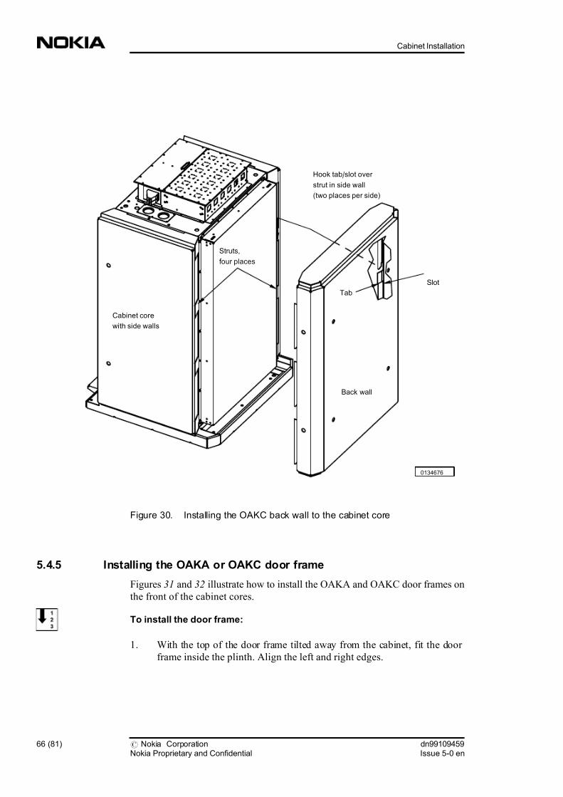
Figure 30. Installing the OAKC back wall to the cabinet core
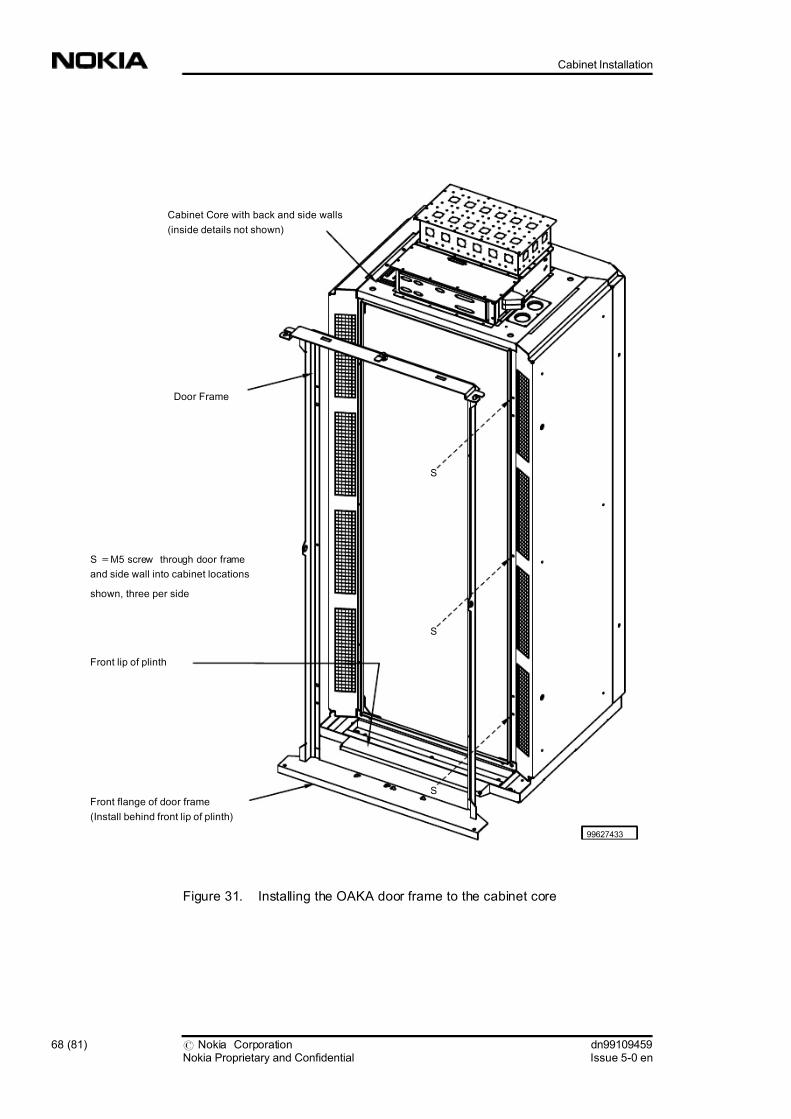
5.4.5 Installing the OAKA or OAKC door frame
Figures 31 and 32 illustrate how to install the OAKA and OAKC door frames on
the front of the cabinet cores.
To install the door frame:
1. With the top of the door frame tilted away from the cabinet, fit the door
frame inside the plinth. Align the left and right edges.
0134676
Cabinet core
with side walls
Back wall
Slot
Tab
Hook tab/slot over
strut in side wall
(two places per side)
Struts,
four places
66 (81) # Nokia CorporationNokia Proprietary and Confidential
dn99109459Issue 5-0 en
Cabinet Installation

7/30/2019 Cabinet Installation
http://slidepdf.com/reader/full/cabinet-installation 67/81
2. Push the top of the door frame against the top of the cabinet.
3. On each side of the door frame, insert three M5 screws through the frame
and into the threaded holes on the front edges of the side walls.
4. Tighten all six screws.
tip:
If the door frame does not fit properly, verify the following:
. The door frame is not upside down.
. Nothing is between the door frame and the cabinet at the contact area.
. Nothing is between the door frame and the plinth at the contact area.
. Nothing is between the door frame and the roof at the contact area.
. The mounting holes on the roof are open.
. The mounting holes of the cabinet are open.
dn99109459Issue 5-0 en
# Nokia CorporationNokia Proprietary and Confidential
67 (81)
Installing the Outdoor cabinet
7/30/2019 Cabinet Installation
http://slidepdf.com/reader/full/cabinet-installation 68/81
Figure 31. Installing the OAKA door frame to the cabinet core
99627433
S =M5 screw through door frame
and side wall into cabinet locations
shown, three per side
Front lip of plinth
Cabinet Core with back and side walls
(inside details not shown)
Door Frame
Front flange of door frame
(Install behind front lip of plinth)
S
S
S
68 (81) # Nokia CorporationNokia Proprietary and Confidential
dn99109459Issue 5-0 en
Cabinet Installation

7/30/2019 Cabinet Installation
http://slidepdf.com/reader/full/cabinet-installation 69/81
Figure 32. Installing the OAKC door frame to the cabinet core
5.4.6 Installing the OAKA or OAKC roof
The OAKA or OAKC roof consists of the following components:
. roof support assembly
. roof
Figure 33 illustrates the installation of the roof support assembly.
S =M5 screw through door frame
and side wall into cabinet locations
shown, two per side
Cabinet Core with back and side walls
(inside details not shown)
0134688
Door Frame
S
S
Front flange of door frame
(Install behind front lip of plinth)
Front lip of plinth
dn99109459Issue 5-0 en
# Nokia CorporationNokia Proprietary and Confidential
69 (81)
Installing the Outdoor cabinet

7/30/2019 Cabinet Installation
http://slidepdf.com/reader/full/cabinet-installation 70/81
To install the roof support assembly to the cabinet core:
1. Remove the roof from the spring-loaded roof hinge pins on the roof
support assembly.
2. Place the roof support assembly on the top of the cabinet core.
3. Align the four holes at the bottom of the roof support assembly with the
four holes on the top of the cabinet core.
4. Insert four M12 bolts through the holes and loosely screw them into the
cabinet core.
5. Align the roof support assembly with the cabinet and tighten the four M12
bolts.
6. Secure the roof support assembly to the door frame with two M5 screws.
Note
You can access the roof latch only when the cabinet door is open.
tip:
If the roof support assembly does not fit properly, verify the following:
. The roof is not backwards.
. Nothing is between the roof and the cabinet at the contact area.
. The mounting holes in the cabinet are open.
70 (81) # Nokia CorporationNokia Proprietary and Confidential
dn99109459Issue 5-0 en
Cabinet Installation

7/30/2019 Cabinet Installation
http://slidepdf.com/reader/full/cabinet-installation 71/81
Figure 33. Installing the roof support assembly to the cabinet core)
Figure 34 illustrates the installation of the roof to the roof support assembly.
To attach the roof to the roof support assembly:
1. Attach the roof to the roof support assembly at the spring-loaded hinge
pins.
2. Close the roof and lock it by turning the roof latch on the door frame to the
left.
99627469
Roof hinge pin,
spring-loaded (two places)
Roof support
(roof not shown)
Secure roof support
to door frame
(two places)
Door
frame
Secure roof support
to cabinet top (four places)
dn99109459Issue 5-0 en
# Nokia CorporationNokia Proprietary and Confidential
71 (81)
Installing the Outdoor cabinet

7/30/2019 Cabinet Installation
http://slidepdf.com/reader/full/cabinet-installation 72/81
Figure 34. Attaching the roof to the roof support assembly
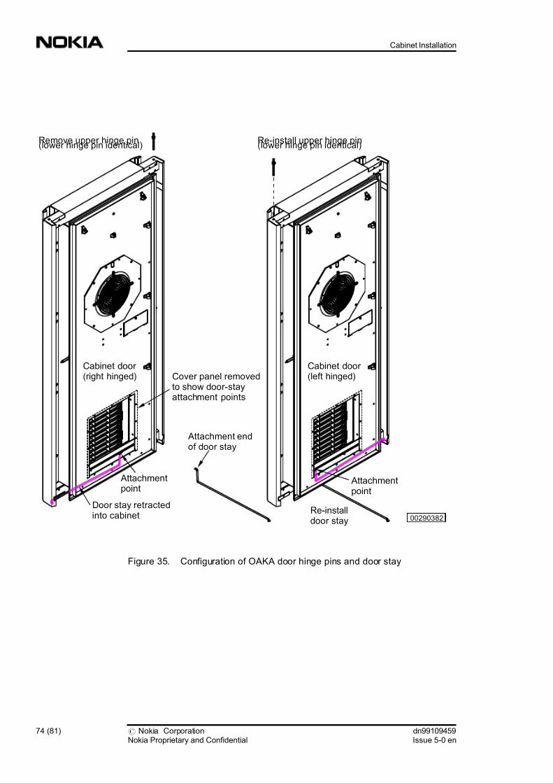
5.4.7 Installing the OAKA or OAKC door
You can install the door of the OAKA or OAKC in a right or left opening
orientation.
Cabinet
Door
Door frame
99627472
Roof
Roof hinge pin,spring-loaded (two places)
Roof support
assembly
Roof Latch
UnlockLock
72 (81) # Nokia CorporationNokia Proprietary and Confidential
dn99109459Issue 5-0 en
Cabinet Installation

7/30/2019 Cabinet Installation
http://slidepdf.com/reader/full/cabinet-installation 73/81
Note
The OAKA door weighs 35 kg (77 lb). A minimum of two installers are required
to install the door.
Figure 35 illustrates how to configure the OAKA or OAKC door hinge pins and
door stay for left or right opening.
Figures 36 and 37 illustrate how to install the OAKA and OAKC doors on the
front of each cabinet core.
To install the door:
1. If the hinge pins are installed in the desired position, skip to step 3.
2. If necessary, move the hinge pins (upper and lower) and door rod to the
desired side of the door (left or right side) as described in steps a through d.
a. Lay the door down with the inside of the door facing up.
b. With a hammer and long-handle screwdriver, tap out upper and
lower hinge pins from the inside.
c. Insert the hinge pins in the opposite side of the door, and gently tap
them into place ensuring the pins are fully seated.
d. Remove the door stay from the bottom of the door and install it in
the opposite side attachment hole.
3. Slide the lower door hinge pin into the lower hinge hole in the door frame.
4. Lift the door and engage the upper hinge pin of the door in the slot at the
top of the door frame.
dn99109459Issue 5-0 en
# Nokia CorporationNokia Proprietary and Confidential
73 (81)
Installing the Outdoor cabinet
7/30/2019 Cabinet Installation
http://slidepdf.com/reader/full/cabinet-installation 74/81
Figure 35. Configuration of OAKA door hinge pins and door stay
00290382
Cabinet door (right hinged)
Cabinet door (left hinged)
Remove upper hinge pin(lower hinge pin identical)
Re-install upper hinge pin(lower hinge pin identical)
Attachment endof door stay
Cover panel removedto show door-stayattachment points
Attachmentpoint
Attachmentpoint
Door stay retractedinto cabinet
Re-installdoor stay
74 (81) # Nokia CorporationNokia Proprietary and Confidential
dn99109459Issue 5-0 en
Cabinet Installation

7/30/2019 Cabinet Installation
http://slidepdf.com/reader/full/cabinet-installation 75/81
Figure 36. Installing the OAKA door to the cabinet
99627457
Cabinet
Door
Upper hinge pin
(lower hinge pin identical)
Hole for lower
hinge pin
Door frame
NOTE: Lower hinge pin,
not visible in this view
Cabinet Core
(inner details not
shown)
dn99109459Issue 5-0 en
# Nokia CorporationNokia Proprietary and Confidential
75 (81)
Installing the Outdoor cabinet

7/30/2019 Cabinet Installation
http://slidepdf.com/reader/full/cabinet-installation 76/81
Figure 37. Installing the OAKC door to the cabinet
Caution
To prevent damage to the cables in windy conditions, use the door stay to hold
the door open. When you close the door, make sure the cables are not between the
door and door frame.
Cabinet
Door
Upper hinge pin
(lower hinge pin identical)
Door frame
Cabinet Core
(inner details not
shown)
0134691
Hole for lower
hinge pin
NOTE: Lower hinge pin,
not visible in this view
76 (81) # Nokia CorporationNokia Proprietary and Confidential
dn99109459Issue 5-0 en
Cabinet Installation

7/30/2019 Cabinet Installation
http://slidepdf.com/reader/full/cabinet-installation 77/81
To install the door grounding strap:
1. If required, remove the grounding strap from the default (left) position and
install it on the right side of the cabinet core.
2. Route the grounding cable through the cable clamp near the top of the
door.
3. Remove the nut from the door cabinet ground stud while holding the star
washer in place.
4. Slide the end of the door grounding strap over the stud and fasten with the
nut.
Figure 38. OAK door grounding
0111784
Cabinet door
Cabinet
ground point
Cable clamp
Grounding
strap
NutLug
Star
washer
Cabinet ground stud (front
corner, behind flange)Core
Mechanics
dn99109459Issue 5-0 en
# Nokia CorporationNokia Proprietary and Confidential
77 (81)
Installing the Outdoor cabinet
7/30/2019 Cabinet Installation
http://slidepdf.com/reader/full/cabinet-installation 78/81
5.4.8 Installing a door lock
The door lock is installed in the cabinet door latch cover to prevent entry into the
cabinet by unauthorised personnel.
Note
For security reasons, the door lock mechanism is not supplied by Nokia.
Figure 39 illustrates how to install a lock mechanism to the cabinet door.
To install a door lock mechanism:
1. Use the key to determine the desired lock rotation.
2. Insert the lock into the lock cover.
3. Secure the lock to the lock cover using the lock clip.
78 (81) # Nokia CorporationNokia Proprietary and Confidential
dn99109459Issue 5-0 en
Cabinet Installation

7/30/2019 Cabinet Installation
http://slidepdf.com/reader/full/cabinet-installation 79/81
Figure 39. Installing the door lock mechanism
5.4.9 Installing the door switch
The door switch automatically turns off the door fan and heater (if installed) when
the door is opened.
Figure 40 illustrates how to install the door switch.
00297621
Locked
Unlocked
Lock clipLock components
Lock clip installed
Lock clip installation direction
Lock cover closed
Lock clip
Lock
Lock
Lock cover
Lock cover
Key
dn99109459Issue 5-0 en
# Nokia CorporationNokia Proprietary and Confidential
79 (81)
Installing the Outdoor cabinet

7/30/2019 Cabinet Installation
http://slidepdf.com/reader/full/cabinet-installation 80/81
To install the door switch:
1. Mount the door switch on the four studs inside the door frame (at the top of
the cabinet).
2. Secure the door switch to the two threaded studs with two M5 nuts
(supplied with the door switch assembly).
3. Plug the door switch connector into the X20 receptacle on the cabinet
power and control interface.
4. Plug the cabinet fan connector into the door switch assembly fan
receptacle.
Figure 40. Door switch installation
S = M5 mounting studs
with nuts behind front flange
(two places)
Cabinet Core
D-15 (F) Cabinet power and control
interface (X20 - second connector from right)
D-15 (M) Connector to
cabinet power and
control interface
Door switchassembly
00275752
From Door Fan Assembly
80 (81) # Nokia CorporationNokia Proprietary and Confidential
dn99109459Issue 5-0 en
Cabinet Installation
7/30/2019 Cabinet Installation
http://slidepdf.com/reader/full/cabinet-installation 81/81
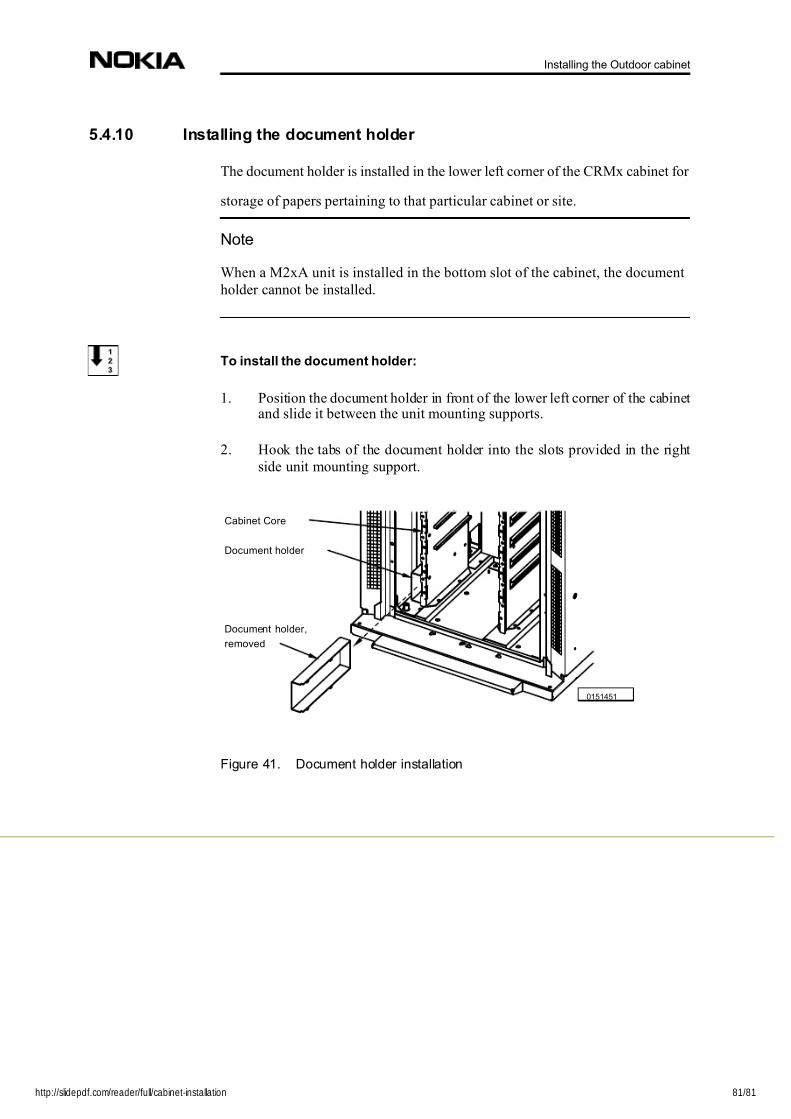
5.4.10 Installing the document holder
The document holder is installed in the lower left corner of the CRMx cabinet for
storage of papers pertaining to that particular cabinet or site.
Note
When a M2xA unit is installed in the bottom slot of the cabinet, the document
holder cannot be installed.
To install the document holder:
1. Position the document holder in front of the lower left corner of the cabinet and slide it between the unit mounting supports.
2. Hook the tabs of the document holder into the slots provided in the right
side unit mounting support.
Figure 41. Document holder installation
0151451
Document holder,
removed
Document holder
Cabinet Core
Installing the Outdoor cabinet