ca A1-A163.qxd:Layout 1 2/9/11 7:48 PM Page 1€¦ · ca_A1-A163.qxd:Layout 1 2/9/11 7:49 PM Page...
25
Transcript of ca A1-A163.qxd:Layout 1 2/9/11 7:48 PM Page 1€¦ · ca_A1-A163.qxd:Layout 1 2/9/11 7:49 PM Page...

ca_A1-A163.qxd:Layout 1 2/9/11 7:48 PM Page 1

A-39www.ittcannon.com
Dimensions shown in inches (mm)Specifications and dimensions subject to change
Circular
A
KPSE High performance crimp contact connectors
KPSE High performance crimp contact connectors
• High performance• Crimp termination• Closed entry socket contacts
Series KPSE environmental, miniature circu-lar, quick disconnect connectors aredesigned for the exacting requirements oftoday’s electronic industry.
They are intermateable, intermountable andinterchangeable with all connectors manu-factured acc. to MIL-C-26482 and VG95328.
1 Standard MIL-C-26482 mates with any connector designed to MIL-C-26482 and VG 95328.
2 Crimp, snap-in contacts are designed to MIL-C-39029 and can be crimped with the standardM22520/1 crimp tool.
Closed-entry socket contacts eliminate dam-age from abuse by test probes and help to correct any misaligned pins duringengagement
Contact insertion is accomplished from therear of the connector. When the contact is fullyinserted, the clip tines snap securely behind thecontact shoulder.
Contact extraction is accomplished with afront-inserted tool. Pressing the tool plungerpushes the contact out through the rear of the connector.
3 Monobloc insulator does not leave any accessto moisture and avoids interfacial empty space.
4 Contact retaining clip is completely encased ina tough plastic wafer to protect the clip fromdamage
Complete moisture sealing is achieved bycombining four seals: shell, peripheral, interfa-cial and wire seals
Shell Seal is effected when the plug shell push-es against the sealing ring in the receptacle when the connectors are mated.
Peripheral Seal around the edge of the pininsulator is designed so that mating the connec-tor puts tension on the seal and greatly reducescompression set.
Interfacial Seal is achieved by the insutor facesmeeting when the plug and receptacle aremated.
Wire Seal is accomplished by a multiple rippledesign, exceeding the wire sealing requirementsof MIL-C-26482.
5 Positive insert-to-shell mechanical retentionwith hard plastic wafer firmly locked into agroove in the shell, in addition to a strongadhesive bond between the insert and shell.
Cannon KPT/KPSEMIL-C-26482 Series I Connectors
ca_A1-A163.qxd:Layout 1 2/9/11 7:49 PM Page 39

A-40www.ittcannon.com
Dimensions shown in inches (mm)Specifications and dimensions subject to change
Circ
ular
A
KPSE High performance crimp contact connectors
SERIES PREFIX
SHELL STYLE
CLASS
SHELL SIZE
CONTACT ARRANGEMENT
CONTACT TYPE
ALTERNATE INSERT POSITION
MODIFICATION CODE
SERIES PREFIXKPSE -ITT Cannon prefixKPSR - ITT Cannon RoHS prefixMS -MIL-C-26482 prefix
SHELL STYLEITT Cannon designation00 -wall mounting receptacle01 -cable connecting plug02 -box mounting receptacle (class E only)06 -straight plug07 -jam nut receptacle08 -90º angle plug
MS DESIGNATION3120 - Wall mounting receptacle3121 - Cable connecting receptacle3122 - Box mounting receptacle3124 - Jam nut receptacle3126 - Straight plug
CLASSA - general duty (not MS approved)B - general duty with strain relief (not MS approved)E - with a grommet seal (MS specification)F - grommet seal with strain relief (MS specification)J - gland seal with strain relief for jacketed cable
(U.S. version) (not MS approved)P -for potting (MS specification) (U.S. version)
SHELL SIZES8, 10, 12, 14, 16, 18, 20, 22, and 24
CONTACT ARRANGEMENTSsee page A-41
MS 3120 E 18 - 32 P X *KSPE 00 E 18 - 32 P X *
CONTACT TYPEP -PinS -Socket
ALTERNATE INSERT POSITIONW, X, and Z (omit for normal), see page A-42
MODIFICATION CODE (Include Same Codes as KPT)A34 - Electroless nickel hardware, RoHS compliant (European
version)A71 - Electroless nickel hardware (U.S. version RoHS compliant
after 11/1/07))A206 - Black zinc cobalt hardware (U.S. version, RoHS compliant)A232 - Black zinc cobalt hardware (European version, RoHS
compliant)A233 - Green zinc cobalt hardware (European version)A408 - Extended Life Contact - Gold over NickelDN - Shrink boot adapter for shell styles 00, 01, 06 and 07
(Class E only)DZ - Endbell for shielding braids and shrink boots.
(Class E only)07 - Clear chromate over cadmium hardware (U.S. version)16 - Lanyard release (applicable to plug only) (U.S. version)23 - Ground springs (applicable to plug only)F42 - connectors without endbell and related parts
P9 = PG9 for shell #10 M12 = M12x1,5 for shell #10P11 = PG11 for shell #12 M16 = M16x1,5 for shell #12P13 = PG13,5 for shell #14 M20 = M20x1,5 for shell #14P16 = PG16 for shell #16 M25 = M25x1,5 for shell #16P21 = PG21 for shell #18 M25 = M25x1,5 for shell #18P21 = PG21 for shell #20 M25 = M25x1,5 for shell #20P21 = PG21 for shell #22 M32 = M32x1,5 for shell #22P29 = PG29 for shell #24 M32 = M32x1,5 for shell #24
Consult factory for other modifications. Omit first digit (0) ofshell style indication when using a modification code.
How to order
Cannon KPT/KPSEMIL-C-26482 Series I Connectors
ca_A1-A163.qxd:Layout 1 2/9/11 7:49 PM Page 40

A-41www.ittcannon.com
Dimensions shown in inches (mm)Specifications and dimensions subject to change
Circular
A
Contact Arrangements
Cannon KPT/KPSEMIL-C-26482 Series I Connectors
8-22-#20
I
KPTKPSEAuthorized per MIL-C-26482 (NAVY)Not MS approved ITTC proprietaryVG95328
LEGEND
AB
B
AC B
A
C
DB
AC
BA
C
DE
FGH
JK
L MN
PR
BA
KL
GM
CDEF
HJB
A
CD
EBA
CDEF
GH
JKB
A
CDE
F
G
HB
AC
20A-6*
BA
CD
E FBA
CDE
F
F
BAL
C
DEG
H
JK M N
PRS
T U
AB
C
DE
FGH
J
KL
MN P
RST
U V
AB
C
DEF
GH
E
D
CB
A
FGHJ
K
L
MN
PR S
TUVW
XY
Z
A BC
D
EF
GHJK
L
M
NP
RS T
UV
WXYZ
a bc
A BC
D
E
FGHJKL
MN
PR
S TUV
WXY Z
AB
C
DE
F
G
HJ
K
L
A BC
D
E
F
GHJK
LM
N
PR
S T U V
W
X
YZa
b
cd
e
A BC
D
E
F
G
H
JKLMN
P
R
S
T
UV
WX
YZ
a
b
cde
fg
h
i
jk
m
nlpq
r
s
AB
C
D
E
F
GH
JKLM
NP
R
S
T
UV
WX
YZ
a
b
c
de
f
g
h
ij
km
n
p
q
r
A
B
C
D
EFG
HJ
K
LM
N
P
R
STU
V
WX
YZ
AB
C
D
EF
G
H
J
K
L
MN
PR
S
AB
C
D
E
FGH
JKL
M
N
P
R
ST
UV
W
X
YZ
ab
c
d
e
fg
h
i
AB
C
D
E
F
GHJ
KL
M
N
P
RS
TU
V
WX
YZa
b
cd e
f
AB
C
D
E
FGH
J
K
L
MN
PR
S
TU
V
W
X
A
B
C
D
EF
GHJ
K
L
N
M P RS
T
UV
WX
Y
Z
ab
c
def
g
hi
AB
C
D
E
F
GHJKL
M
N
P
R
ST
UVW
X
YZa
b
c
de
f
ghij
k
AB
C
D
E
FG
HJKL
M
N
P
R
ST U
VW
X
YZab
c
de
f g h
i
kl
m n
AB
CD
E
F
G
H
JK
LMNP
R
S
T
U
V
WX
YZ
a
b
l
k
c
d
ef
g
h
i
j mn
pq
r
s
AB
C
D
E
F
G
HJK
L
M
N
P
R
ST
UV
WX
Y
Z
a
bc
d
e
fg
h
i
j
km
np
qr
s
tu
vw
x
y
zAA
BBCC
DDEE
FF
GGHH
AB
C
D
E
F
G
H
JK
LMNP
R
S
T
U
V
W
XY
Z a bc
d
e
f
g
hikm
n
p
q
r
st
u
vw
xy
zAA
BB
CCDD
EEFF
GG
HH
JJ
KKLL
Drawing not to scale; face view of pin insert shown (socket view is opposite)
Shell Size 8
Shell SizeNo. of ContactsService Rating
Shell SizeNo. of ContactsService Rating
Shell SizeNo. of ContactsService Rating
Shell SizeNo. of ContactsService Rating
Shell SizeNo. of ContactsService Rating
Shell SizeNo. of ContactsService Rating
Shell Size 10 Shell Size 12 Shell Size 14
Shell Size 16 Shell Size 18
Shell Size 20
Shell Size 22
Shell Size 24
8-33-#20
I
B
AC
8-3A3-#20
I
8-44-#20
I
8-333-#20
I
10-66-#20
I
10-77-#20
I
10-986-#20
I
12-33-#16
II
12-88-#20
I
12-1414-#20
I
12-1010-#20
I
14-55-#16
II
14-128-#20 4-#16
I
14-1514-#20 1-#16
I
14-1818-#20
I
14-1919-#20
I
14-224-#121-#20
I
14A-4COAX RG1884(Not for Receptacle
Shell Style 02)
I
16-88-#16
II
16-2322-#20 1-#16
I
16-2626-#20
I
16-9921-#20 2-#16
I
18-1111-#16
II
18A2826-#20 2-#16
I
18-3029-#20 1-#16
I
18-3232-#20
I
20-1616-#16
II
20-2424-#20
I
20-3937-#20 2-#16
I
20-4141-#20
I
22-2121-#16
II
22-3232-#20
I
22-3434-#20
I
22-3636-#20
I
22-4127-#20 14-#16
I
22-5555-#20
I
24A5755-#20 2-#12
I
24-6161-#20
I
20A-65-#12*
I
*Note: Contacts are1 Grounding Pin &4 Standard Size 12 pins
AB
C
D
E
F
G
H
JK
LMP
N
R
S
T
U
V
W
XY
Z a bc
d
e
f
g
h
ijkm
n
p
q
r
s
tu v
wx
y
zAA
BBCC
DD
EE
FF
GG HH
JJ
KK
LL
MM
NN
PP
BA
DC
FEG
A
PN
J
K ML
R
HFED
B C
A
BC
DBA
CD
E
EA
CD
B
ca_A1-A163.qxd:Layout 1 2/9/11 7:49 PM Page 41

A-42www.ittcannon.com
Dimensions shown in inches (mm)Specifications and dimensions subject to change
Circ
ular
A
† Not available in KPSE LA, LBF, LE, L J and LP are connector overall lengths
Alternate Insert Positions
Face view of pin inserts
The five positions (W,X,Y,Z and Normal) differ in degree or rotation for various sizes and arrangements
No. of Shell Arr. Degrees of RotationContacts Size No. W X Y Z
2 8 8-2 58 122 - -3 8 8-3 60 210 .- -3 8 8-3A* 60 - - -3 8 8-33 90 - - -3 12 12-3 - - 180 -4 8 8-4 45 - - -5 14 14-5 40 92 184 2735 14 14-22 ** ** ** **5 20 20A-6* 90 180 270 -6 10 10-6 90 - - -6 10 10-98 90 180 240 2707 10 10-7* ** ** ** **8 12 12-8 90 112 203 2928 16 16-8 54 152 180 331
10 12 12-10 60 155 270 29511 18 18-11 62 119 241 34012 14 14-12 43 90 - -14 12 12-14* ** ** ** **15 14 14-15 17 110 155 23416 20 20-16 238 318 333 34718 14 14-18 15 90 180 27019 14 14-19 30 165 315 -21 22 22-21 16 135 175 34923 16 16-23 158 270 - -23 16 16-99 66 156 223 34024 20 20-24 70 145 215 29026 16 16-26 60 - 275 33828 18 18A26* - - - -30 18 18-30 180 193 285 35032 18 18-32 85 138 222 26532 22 22-32 72 145 215 28834 22 22-34 62 142 218 29836 22 22-36* 72 144 216 28839 20 20-39 63 144 252 33341 20 20-41 45 126 225 -41 22 22-41 39 135 264 -55 22 22-55 30 142 226 31457 24 24A57* 90 180 270 32461 24 24-61 90 180 270
* Contact arrangements not MIL-C-26482 qualified
N
W*
X*
Y*
Z*
Cannon KPT/KPSEMIL-C-26482 Series I Connectors
ca_A1-A163.qxd:Layout 1 2/9/11 7:49 PM Page 42
A-43www.ittcannon.com
Dimensions shown in inches (mm)Specifications and dimensions subject to change
Circular
A
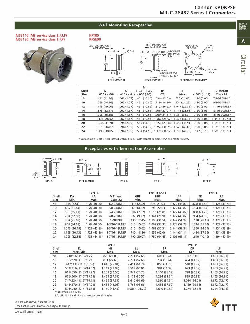
† Not available in KPSE LA, LBF, LE, L J and LP are connector overall lengths
TYPE J TYPE PShell DJ HJ L J BP DP LPSize Max./Min. Max. Max. Max. Min. Max.†8 .230/.168 (5.84/4.27) .828 (21.03) 2.271 (57.68) .608 (15.44) .317 (8.05) 1.453 (36.91)10 .312/.205 (7.92/5.21) .891 (22.63) 2.271 (57.68) .734 (18.64) .434 (11.02) 1.453 (36.91)12 .442/.338 (11.23/8.59) 1.016 (25.81) 2.411 (61.24) .858 (21.79) .548 (13.92) 1.453 (36.91)14 .539/.416 (13.56/10.57) 1.141 (28.98) 2.599 (66.01) .984 (24.99) .673 (17.09) 1.453 (36.91)16 .616/.550 (15.65/13.97) 1.203 (30.56) 2.943 (74.75) 1.110 (28.19) .798 (20.27) 1.453 (36.91)18 .672/.600 (17.07/15.24) 1.469 (37.31) 3.172 (80.57) 1.234 (31.34) .899 (20.83) 1.453 (36.91)20 .747/.634 (18.97/16.13) 1.469 (37.31) 3.610 (91.69) 1.360 (34.54) 1.024 (26.01) 1.672 (42.47)22 .846/.670 (21.49/17.02) 1.656 (42.06) 3.766 (95.66) 1.484 (37.69) 1.149 (29.18) 1.672 (42.47)24 .894/.740 (22.71/18.80) 1.750 (44.45) 3.985 (101.22) 1.610 (40.89) 1.274 (32.36) 1.734 (44.04)
MShell A K +.031 (+.79) R* S T Q ThreadSize ±.003 (±.08) ±.016 (±.41) -.000 (.00) (TP) Max. ±.005 (±.13) Class 2A†8 .471 (11.96) .062 (1.57) .431 (10.95) .594 (15.09) .828 (21.03) .120 (3.05) 7/16-28UNEF10 .588 (14.96) .062 (1.57) .431 (10.95) .719 (18.26) .954 (24.23) .120 (3.05) 9/16-24UNEF12 .748 (19.00) .062 (1.57) .431 (10.95) .812 (20.62) 1.047 (26.59) .120 (3.05) 11/16-24UNEF14 .873 (22.17) .062 (1.57) .431 (10.95) .906 (23.01) 1.141 (28.98) .120 (3.05) 13/16-20UNEF16 .998 (25.35) .062 (1.57) .431 (10.95) .969 (24.61) 1.234 (31.34) .120 (3.05) 15/16-20UNEF18 1.123 (28.52) .062 (1.57) .431 (10.95) 1.062 (26.97) 1.328 (33.73) .120 (3.05) 1-1/16-18UNEF20 1.248 (31.70) .094 (2.39) .556 (14.12) 1.156 (29.36) 1.453 (36.91) .120 (3.05) 1-3/16-18UNEF22 1.373 (34.87) .094 (2.39) .556 (14.12) 1.250 (31.75) 1.578 (40.08) .120 (3.05) 1-5/16-18UNEF24 1.498 (38.05) .094 (2.39) .589 (14.96) 1.375 (34.92) 1.703 (43.26) .147 (3.73) 1-7/16-18UNEF
TYPE A TYPE B and F TYPE EShell DA LA V Thread GBF HBF LBF BE LESize Min. Max. Class 2A Min. Max. Max. Max. Max.†8 .335 (8.51) 1.58 (40.00) 1/2-28UNEF .115 (2.92) .828 (21.03) 1.922 (48.82) .608 (15.44) 1.328 (33.73)10 .466 (11.84) 1.58 (40.00) 5/8-24UNEF .178 (4.52) .891 (22.63) 1.922 (48.82) .734 (18.64) 1.328 (33.73)12 .591 (15.01) 1.58 (40.00) 3/4-20UNEF .302 (7.67) 1.016 (25.81) 1.922 (48.82) .858 (21.79) 1.328 (33.73)14 .700 (17.90) 1.58 (40.00) 7/8-20UNEF .365 (9.27) 1.141 (28.98) 1.922 (48.82) .984 (24.99) 1.328 (33.73)16 .830 (21.08) 1.58 (40.00) 1-20UNEF .490 (12.45) 1.203 (30.56) 2.047 (51.99) 1.110 (28.19) 1.328 (33.73)18 .948 (24.08) 1.58 (40.00) 1-3/16-18UNEF .615 (15.62) 1.469 (37.31) 2.078 (52.78) 1.234 (31.34) 1.328 (33.73)20 1.043 (26.49) 1.728 (43.89) 1-3/16-18UNEF .615 (15.62) 1.469 (37.31) 2.344 (59.54) 1.360 (34.54) 1.531 (38.89)22 1.198 (30.43) 1.728 (43.89) 1-7/16-18UNEF .740 (18.80) 1.656 (42.06) 1.344 (34.14) 1.484 (37.69) 1.531 (38.89)24 1.293 (32.84) 1.738 (44.15) 1-7/16-18UNEF .790 (20.07) 1.750 (44.45) 2.406 (61.11) 1.610 (40.49) 1.594 (40.49)
MS3110 (MS service class E,F,J,P) KPT00MS3120 (MS service class E,F,P) KPSE00
† Not available in KPSE *(TP) located within .010 T.P. with respect to diameter A and master keyway.
Wall Mounting Receptacles
Receptacles with Termination Assemblies
Q Thd.M
K
SEE TERMINATIONASSEMBLY
A DIA
SOLDERKPT00/MS3110
A DIA
M K
SEE TERMINATIONASSEMBLY
Q THD
CRIMPKPSE00/MS3120
GROMMET FORTYPES A, B, J & P
GROMMETFOR TYPESE & F
RECEPTACLE ASSEMBLY
SR (TP)
.140 RADMAX
POLARIZINGGROOVE
T DIA4 MTGHOLES
V THD
TYPE A
DA
LA
.395(10.03)
MNTYPE B AND F
HBFGBF
LBF
BE
LE
HJ
L J
DJ
LP
BP HJ
TYPE E TYPE J TYPE P
Cannon KPT/KPSEMIL-C-26482 Series I Connectors
ca_A1-A163.qxd:Layout 1 2/9/11 7:49 PM Page 43

A-44www.ittcannon.com
Dimensions shown in inches (mm)Specifications and dimensions subject to change
Circ
ular
A
Cable Connecting Plugs
MS3111 (MS service class E,F,J,P) KPT01MS3121 (MS service class E,F,P) KPSE01
P
Shell A HJ +.031 (+.79) S Y Q ThreadSize ±.003 (±.08) ±.016 (±.41) -.000 (-.00) Max. Max. Class 2A†8 .471 (11.96) .094 (2.39) .400 (10.16) .828 (21.03) .958 (24.33) 7/16-28UNEF10 .588 (14.94) .094 (2.39) .400 (10.16) .954 (24.23) 1.082 (27.48) 9/16-24UNEF12 .748 (19.00) .094 (2.39) .400 (10.16) 1.047 (26.59) 1.176 (29.87) 11/16-24UNEF14 .873 (22.17) .094 (2.39) .400 (10.16) 1.141 (24.99) 1.270 (32.26) 13/16-20UNEF16 .998 (25.35) .094 (2.39) .400 (10.16) 1.110 (28.98) 1.364 (34.65) 15/16-20UNEF18 1.123 (28.52) .094 (2.39) .400 (10.16) 1.234 (31.34) 1.458 (37.03) 1-1/16-18UNEF20 1.248 (31.70) .115 (2.92) .535 (13.59) 1.328 (33.73) 1.582 (40.18) 1-3/16-18UNEF22 1.373 (34.87) .115 (2.92) .535 (13.59) 1.578 (40.08) 1.708 (43.38) 1-5/16-18UNEF24 1.498 (38.05) .115 (2.92) .558 (14.43) 1.703 (43.26) 1.832 (46.53) 1-7/16-18UNEF
† Not available in KPSE *(TP) located within .010 T.P. with respect to diameter A and master keyway.
PLUG ASSEMBLY
POLARIZINGGROOVE
S
Y Dia.
CRIMPKPSE01/MS3121
SOLDERKPT01/MS3111
SEE TERMINATIONASSEMBLY
SEE TERMINATIONASSEMBLY
A Dia.
Q THDH
PH
A Dia.
Q THD
GROMMET FORTYPES E & F
GROMMET FORTYPES A, B, J & P
P
Cannon KPT/KPSEMIL-C-26482 Series I Connectors
TYPE J TYPE PShell DJ HJ L J BP DP LPSize Max./Min. Max. Max. Max. Min. Max.†8 .230/.168 (5.84/4.27) .828 (21.03) 2.271 (57.68) .608 (15.44) .317 (8.05) 1.453 (36.91)10 .312/.205 (7.92/5.21) .891 (22.63) 2.271 (57.68) .734 (18.64) .434 (11.02) 1.453 (36.91)12 .442/.338 (11.23/8.59) 1.016 (25.81) 2.411 (61.24) .858 (21.79) .548 (13.92) 1.453 (36.91)14 .539/.416 (13.56/10.57) 1.141 (28.98) 2.599 (66.01) .984 (24.99) .673 (17.09) 1.453 (36.91)16 .616/.550 (15.65/13.97) 1.203 (30.56) 2.943 (74.75) 1.110 (28.19) .798 (20.27) 1.453 (36.91)18 .672/.600 (17.07/15.24) 1.469 (37.31) 3.172 (80.57) 1.234 (31.34) .899 (20.83) 1.453 (36.91)20 .747/.634 (18.97/16.13) 1.469 (37.31) 3.610 (91.69) 1.360 (34.54) 1.024 (26.01) 1.672 (42.47)22 .846/.670 (21.49/17.02) 1.656 (42.06) 3.766 (95.66) 1.484 (37.69) 1.149 (29.18) 1.672 (42.47)24 .894/.740 (22.71/18.80) 1.750 (44.45) 3.985 (101.22) 1.610 (40.89) 1.274 (32.36) 1.734 (44.04)
TYPE A TYPE B and F TYPE EShell DA LA V Thread GBF HBF LBF BE LESize Min. Max. Class 2A Min. Max. Max. Max. Max.†8 .335 (8.51) 1.50 (38.00) 1/2-28UNEF .115 (2.92) .828 (21.03) 1.922 (48.82) .608 (15.44) 1.328 (33.73)10 .466 (11.84) 1.50 (38.00) 5/8-24UNEF .178 (4.52) .891 (22.63) 1.922 (48.82) .734 (18.64) 1.328 (33.73)12 .591 (15.01) 1.50 (38.00) 3/4-20UNEF .302 (7.67) 1.016 (25.81) 1.922 (48.82) .858 (21.79) 1.328 (33.73)14 .700 (17.90) 1.50 (38.00) 7/8-20UNEF .365 (9.27) 1.141 (28.98) 1.922 (48.82) .984 (24.99) 1.328 (33.73)16 .830 (21.08) 1.50 (38.00) 1-20UNEF .490 (12.45) 1.203 (30.56) 2.047 (51.99) 1.110 (28.19) 1.328 (33.73)18 .948 (24.08) 1.50 (38.00) 1-3/16-18UNEF .615 (15.62) 1.469 (37.31) 2.078 (52.78) 1.234 (31.34) 1.328 (33.73)20 1.043 (26.49) 1.728 (43.89) 1-3/16-18UNEF .615 (15.62) 1.469 (37.31) 2.344 (59.54) 1.360 (34.54) 1.531 (38.89)22 1.198 (30.43) 1.728 (43.89) 1-7/16-18UNEF .740 (18.80) 1.656 (42.06) 1.344 (34.14) 1.484 (37.69) 1.531 (38.89)24 1.293 (32.84) 1.738 (44.15) 1-7/16-18UNEF .790 (20.07) 1.750 (44.45) 2.406 (61.11) 1.610 (40.49) 1.594 (40.49)
Cable Connecting Plugs with Termination Assemblies
V THD
TYPE A
DA
LA
.395(10.03)
MNTYPE B AND F
HBFGBF
LBF
BE
LE
HJ
L J
DJ
LP
BP HJ
TYPE J TYPE PTYPE E
ca_A1-A163.qxd:Layout 1 2/9/11 7:49 PM Page 44

A-45www.ittcannon.com
Dimensions shown in inches (mm)Specifications and dimensions subject to change
Circular
A
Box Mounting Receptacles
M NShell A B K L +.031 (+.79) Dia. R* S T ZSize ±.003 (±.08) Max. ±.016 (±.41) Max. -.000 (-.00) Max. (TP) Max. ±.005 Max.
†8 .471 (11.96) .978 (24.84) .062 (1.57) 1.320 (33.07) .431 (10.95) .469 (11.91) .594 (15.09) .828 (21.03) .120 (3.05) .354 (8.99)
10 .588 (14.96) .978 (24.84) .062 (1.57) 1.320 (33.07) .431 (10.95) .593 (15.06) .719 (18.26) .954 (24.23) .120 (3.05) .354 (8.99)
12 .748 (19.00) .978 (24.84) .062 (1.57) 1.320 (33.07) .431 (10.95) .719 (18.26) .812 (20.62) 1.047 (26.59) .120 (3.05) .354 (8.99)
14 .873 (22.17) .978 (24.84) .062 (1.57) 1.320 (33.07) .431 (10.95) .843 (21.41) .906 (23.01) 1.141 (28.98) .120 (3.05) .354 (8.99)
16 .998 (25.35) .978 (24.84) .062 (1.57) 1.320 (33.07) .431 (10.95) .969 (24.61) .969 (24.61) 1.234 (31.34) .120 (3.05) .354 (8.99)
18 1.123 (28.52) .978 (24.84) .062 (1.57) 1.320 (33.07) .431 (10.95) 1.093 (27.76) 1.062 (26.97) 1.328 (33.73) .120 (3.05) .354 (8.99)
20 1.248 (31.70) 1.196 (30.38) .094 (2.39) 1.387 (34.72) .556 (14.12) 1.219 (30.96) 1.156 (29.36) 1.453 (36.91) .120 (3.05) .417 (10.59)
22 1.373 (34.87) 1.196 (30.38) .094 (2.39) 1.387 (34.72) .556 (14.12) 1.343 (34.11) 1.250 (31.75) 1.578 (40.08) .120 (3.05) .417 (10.59)
24 1.498 (38.05) 1.196 (30.38) .094 (2.39) 1.418 (36.02) .589 (14.96) 1.469 (37.31) 1.375 (34.92) 1.703 (43.26) .147 (3.73) .445 (11.30)
MS3112 (MS service class E) KPT02MS3122 (MS service class E) KPSE02
Note: Connector does not accomodate backshell.
† Not available in KPSE *(TP) located within .010 T.P. with respect to diameter A and master keyway.
SR (TP)
.140 RADMAX
POLARIZINGGROOVE
T DIA4 MTGHOLES
RECEPTACLE ASSEMBLY
A DIA
M
CRIMPKPSE02/MS3122
SOLDERKPT02/MS3112
NDIA
L
K
NDIA
BM
A DIA
KZ
Cannon KPT/KPSEMIL-C-26482 Series I Connectors
ca_A1-A163.qxd:Layout 1 2/9/11 7:49 PM Page 45

A-46www.ittcannon.com
Dimensions shown in inches (mm)Specifications and dimensions subject to change
Circ
ular
A
Straight Plugs
Straight Plugs with Termination Assemblies
MS3116 (MS service class E,F,J,P) KPT06MS3126 (MS service class E,F,P) KPSE06
Shell A Dia. G J Q ThreadSize Max. Max. ±.010 (±0.25) Class 2A†8 .765 (19.43) .782 (19.86) .353 (8.99) 7/16-28UNEF10 .840 (21.34) .926 (23.52) .353 (8.99) 9/16-24UNEF12 .999 (25.38) 1.043 (26.49) .353 (8.99)) 11/16-24UNEF14 1.139 (28.93) 1.183 (30.05) .353 (8.99) 13/16-20UNEF16 1.261 (32.03) 1.305 (33.15) .353 (8.99) 15/16-20UNEF18 1.337 (33.96) 1.391 (35.33) .353 (8.99) 1-1/16-18UNEF20 1.477 (37.52) 1.531 (38.89) .415 (10.54) 1-3/16-18UNEF22 1.602 (40.69) 1.656 (42.06) .415 (10.54) 1-5/16-18UNEF24 1.723 (43.76) 1.777 (45.14) .415 (10.54) 1-7/16-18UNEF
† Not available in KPSE
TYPE A TYPE B and F TYPE EShell DA LA V Thread GBF HBF LBF BE LESize Min. Max. Class 2A Min. Max. Max. Max. Max.†8 .335 (8.51) 1.440 (36.58) 1/2-28UNEF .115 (2.92) .828 (21.03) 1.906 (48.41) .608 (15.44) 1.328 (33.73)10 .466 (11.84) 1.440 (36.58) 5/8-24UNEF .178 (4.52) .891 (22.63) 1.906 (48.41) .734 (18.64) 1.328 (33.73)12 .591 (15.01) 1.440 (36.58) 3/4-20UNEF .302 (7.67) 1.016 (25.81) 1.906 (48.41) .858 (21.79) 1.328 (33.73)14 .700 (17.90) 1.440 (36.58) 7/8-20UNEF .365 (9.27) 1.141 (28.98) 1.906 (48.41) .984 (24.99) 1.328 (33.73)16 .830 (21.08) 1.440 (36.58) 1-20UNEF .490 (12.45) 1.203 (30.56) 2.047 (51.99) 1.110 (28.19) 1.328 (33.73)18 .948 (24.08) 1.662 (42.21) 1-3/16-18UNEF .615 (15.62) 1.469 (37.31) 2.078 (52.78) 1.234 (31.34) 1.328 (33.73)20 1.043 (26.49) 1.662 (42.21) 1-3/16-18UNEF .615 (15.62) 1.469 (37.31) 2.250 (57.15) 1.360 (34.54) 1.453 (36.91)22 1.198 (30.43) 1.662 (42.21) 1-7/16-18UNEF .740 (18.80) 1.656 (42.06) 2.250 (57.15)) 1.484 (37.69) 1.453 (36.91)24 1.293 (32.84) 1.672 (42.47) 1-7/16-18UNEF .790 (20.07) 1.750 (44.45) 2.312 (58.72) 1.610 (40.49) 1.510 (38.54)
TYPE J TYPE PShell DJ HJ L J BP DP LPSize Max./Min. Max. Max. Max. Min. Max.†8 .230/.168 (5.84/4.27) .828 (21.03) 2.271 (57.68) .608 (15.44) .317 (8.05) 1.500 (38.10)10 .312/.205 (7.92/5.21) .891 (22.63) 2.271 (57.68) .734 (18.64) .434 (11.02) 1.500 (38.10)12 .442/.338 (11.23/8.59) 1.016 (25.81) 2.411 (61.24) .858 (21.79) .548 (13.92) 1.500 (38.10))14 .539/.416 (13.56/10.57) 1.141 (28.98) 2.599 (66.01) .984 (24.99) .673 (17.09) 1.500 (38.10)16 .616/.550 (15.65/13.97) 1.203 (30.56) 2.943 (74.75) 1.110 (28.19) .798 (20.27) 1.500 (38.10)18 .672/.600 (17.07/15.24) 1.469 (37.31) 3.172 (80.57) 1.234 (31.34) .899 (20.83) 1.500 (38.10)20 .747/.634 (18.97/16.13) 1.469 (37.31) 3.610 (91.69) 1.360 (34.54) 1.024 (26.01) 1.609 (40.87)22 .846/.670 (21.49/17.02) 1.656 (42.06) 3.766 (95.66) 1.484 (37.69) 1.149 (29.18) 1.609 (40.87)24 .894/.740 (22.71/18.80) 1.750 (44.45) 3.985 (101.22) 1.610 (40.89) 1.274 (32.36) 1.687 (42.85)
† Not available in KPSE LA, LBF, LE, L J and LP are connector overall lengths
ADIA
SOLDERKPT06/MS3116
SEE TERMINATIONASSEMBLY CRIMPKPSE06/MS3126
ADIA
G
POLARIZINGGROOVE
Q THD Q THD GROMMET FORTYPES A, B, J & P
GROMMET FORTYPES E & F
V THD
TYPE A
DA
LA
.395(10.03)
MNTYPE B AND F
HBFGBF
LBF
BE
LE
HJ
L J
DJ
LP
BP HJ
TYPE E TYPE J TYPE P
Cannon KPT/KPSEMIL-C-26482 Series I Connectors
ca_A1-A163.qxd:Layout 1 2/9/11 7:49 PM Page 46

A-47www.ittcannon.com
Dimensions shown in inches (mm)Specifications and dimensions subject to change
Circular
A
Jam Nut Receptacles
Jam Nut Receptacles with Termination Assemblies
M T Shell A A H K +.031 (+.08) N S Panel Thickness R ThreadSize ±.003 (±.08) ±.005 (0.130) ±.017 (±.43) ±.020 (±.05) -.000 (-.00) Max. Max. Min. Max. Class 2A
†8 .471 (11.96) .525 (13.34) .750 (19.05) .117 (2.97) .691 (17.55) 1.078 (27.38) .954 (15.09) .062 (1.57) .125 (3.17) 9/16-24UNEF
10 .588 (14.96) .650 (16.51) .875 (22.22) .117 (2.97) .691 (17.55) 1.206 (30.56) 1.078 (27.38) .062 (1.57) .125 (3.17) 11/16-24UNEF
12 .748 (19.00) .813 (20.65) 1.062 (26.97) .117 (2.97) .691 (17.55) 1.319 (35.33) 1.266 (32.16) .062 (1.57) .125 (3.17) 7/8-20UNEF
14 .873 (22.17) .937 (23.80) 1.188 (30.17) .117 (2.97) .691 (17.55) 1.516 (38.51) 1.391 (35.33) .062 (1.57) .125 (3.17) 1-20UNEF
16 .998 (25.35) 1.061 (26.95) 1.312 (33.32) .117 (2.97) .691 (17.55) 1.641 (41.68) 1.516 (38.51) .062 (1.57) .125 (3.17) 1-1/8-18UNEF
18 1.123 (28.52) 1.186 (30.12) 1.438 (36.25) .117 (2.97) .691 (17.55) 1.766 (44.86) 1.641 (41.68) .062 (1.57) .125 (3.17) 1-1/4-18UNEF
20 1.248 (31.70) 1.311 (33.30) 1.562 (39.67) .148 (3.76) .879 (22.33) 1.954 (49.63) 1.828 (46.43) .062 (1.57) .250 (6.35) 1-3/8-18UNEF
22 1.373 (34.87) 1.436 (36.47) 1.688 (42.87) .148 (3.76) .879 (22.33) 2.078 (52.78) 1.954 (49.63) .062 (1.57) .250 (6.35) 1-1/2-18UNEF
24 1.498 (38.05) 1.561 (39.65) 1.812 (46.02) .148 (3.76) .912 (23.16) 2.203 (55.96) 2.078 (52.78) .062 (1.57) .250 (6.35) 1-5/8-18UNEF
† Not available in KPSE
MS3114 (MS service class E,F,P) KPT07MS3124 (MS service class E,F,P) KPSE07
MK
Q THD
TR THD
ADIA
R THD
ADIA
MK
H
S
N DIA
FMTGFLAT
GROMMET FORTYPE E&F
GROMMET FORTYPE A,B&P
SOLDERKPT07/MS3114
CRIMPKPSE07MS3124
TYPE A TYPE B and F TYPE E TYPE P Shell Z HBF GBF LBF BE LE BP DP LPSize Max. Max. Min. Max. Max. Max. Max. Min. Max.
†8 .312 (7.92) .828 (21.03) .115 (2.92) 1.906 (48.41) .655 (16.64) 1.344 (34.14) .608 (15.44) .317 (8.05) 1.391 (35.33)10 .312 (7.92) .891 (22.63) .178 (4.52) 1.906 (48.41) .843 (21.41) 1.344 (34.14) .734 (18.64) .434 (11.02) 1.391 (35.33)12 .312 (7.92) 1.016 (25.81) .302 (7.67) 1.906 (48.41) .968 (24.59) 1.344 (34.14) .858 (21.79) .548 (13.92) 1.391 (35.33)14 .312 (7.92) 1.141 (28.98) .365 (9.27) 1.906 (48.41) 1.093 (27.76) 1.344 (34.14) .984 (24.99) .673 (17.09) 1.391 (35.33)16 .312 (7.92) 1.203 (30.56) .490 (12.45) 2.047 (51.99) 1.218 (30.94) 1.344 (34.14) 1.110 (28.19) .798 (20.27) 1.391 (35.33)18 .312 (7.92) 1.469 (37.31) .615 (15.62) 2.078 (52.78) 1.343 (34.11) 1.344 (34.14) 1.234 (31.34) .899 (22.83) 1.391 (35.33)20 .193 (4.90) 1.469 (37.31) .615 (15.62) 2.328 (59.13) 1.500 (38.10) 1.594 (40.49) 1.360 (34.54) 1.024 (26.01) 1.641 (41.68)22 .193 (4.90) 1.656 (42.06) .740 (18.80) 2.328 (59.13) 1.625 (41.28) 1.594 (40.49) 1.484 (37.69) 1.149 (29.18) 1.641 (41.68)24 .150 (3.81) 1.750 (44.45) .790 (20.07) 2.453 (62.31) 1.750 (44.45) 1.641 (41.68) 1.610 (40.89) 1.274 (32.36) 1.703 (43.26)
LBF, LE, and LP are connector overall lengths.
LP
DP BP
LE
BE
LBF
HBFGBF
Z
TYPE A(No Term. Assy.)
Cannon KPT/KPSEMIL-C-26482 Series I Connectors
ca_A1-A163.qxd:Layout 1 2/9/11 7:49 PM Page 47

A-48www.ittcannon.com
Dimensions shown in inches (mm)Specifications and dimensions subject to change
Circ
ular
A
Right Angle Plugs
KPT08/KPSE08
Right Angle Plugs with Termination Assemblies
KPT/KPSEShell A Dia. G Q ThreadSize Max. Max. Class 2A†8 .765 (19.43) .782 (19.86) 7/16-28UNEF10 .866 (22.00) .926 (23.52) 9/16-24UNEF12 1.031 (26.20) 1.043 (26.49) 11/16-24UNEF14 1.157 (29.40) 1.183 (30.05) 13/16-20UNEF16 1.291 (32.80) 1.305 (33.15) 15/16-20UNEF18 1.394 (35.40) 1.391 (35.33) 1-1/16-18UNEF20 1.535 (39.00) 1.531 (38.89) 1-3/16-18UNEF22 1.657 (42.10) 1.656 (42.06) 1-5/16-18UNEF24 1.780 (45.20) 1.777 (45.14) 1-7/16-18UNEF
† Not available in KPSENOTE: for size 10 and 24 consult factory for availability in type A,B,E and F.For size 8 consult factory for availability in Type P.
TYPE A and E TYPE B and F TYPE P Shell LAE DAE V Thread DBF LBF L AP LP CP
Size Max. Max. Class 2A Max. Max. Max. Max. Min.Max.
†8 1.421 (36.09) .822 (20.88) 1/2-28UNEF 1.238 (31.44) 1.421 (36.09) 1.842 (46.79) -(-) -(-) -(-)10 1.484 (37.69) .853 (21.67) 5/8-28UNEF 1.269 (32.24) 1.484 (37.69) 1.937 (49.20) 1.030 (26.16) 1.380 (35.05) .252 (6.40)12 1.546 (39.27) .916 (23.27) 3/4-20UNEF 1.395 (35.43) 1.546 (39.27) 2.091 (53.10) 1.030 (26.16) 1.567 (39.80) .252 (6.40)14 1.577 (40.05) .978 (24.84) 7/8-20UNEF 1.519 (38.58) 1.577 (40.05) 2.173 (55.20) 1.030 (26.16) 1.567 (39.80) .283 (7.19)16 1.609 (40.87) 1.041 (26.44) 1-20UNEF 1.582 (40.18) 1.609 (40.87) 2.238 (56.85) 1.280 (32.51) 1.567 (39.80) .355 (9.02)18 1.734 (44.04) 1.103 (28.70) 1-3/16-18UNEF 1.644 (41.76) 1.734 (44.04) 2.455 (62.35) 1.280 (32.51) 1.755 (44.58) .530 (13.46)20 1.879 (47.73) 1.166 (29.62) 1-3/16-18UNEF 1.707 (43.36) 1.879 (47.73) 2.629 (66.78) 1.530 (38.86) 1.782 (45.26) .562 (14.27)22 2.035 (51.69) 1.245 (31.62) 1-7/16-18UNEF 1.884 (47.85) 2.035 (51.69) 2.815 (71.51) 1.530 (38.86) 1.782 (45.26) .562 (14.27)24 2.035 (51.69) 1.322 (33.58) 1-7/16-18UNEF 1.963 (49.86) 2.035 (51.69) 2.902 (73.70) 1.780 (45.21) 2.087 (53.01) .610 (15.49)
† Not available in KPSE.NOTE: For size 10 and 24 consult factory for availability in type A,B,E and F. For size 8 consult factory for availability in Type P.
KPT08
G
POLARIZINGBOSS
Q THD
A DIA
A DIA
Q THDGROMMET FOR
TYPES E&F
GROMMET FORTYPES A,B,J&P
KPSE08
AP
CP
LP
DBF
L MAXLBF
DAE
LAE V THD
Cannon KPT/KPSEMIL-C-26482 Series I Connectors
ca_A1-A163.qxd:Layout 1 2/9/11 7:49 PM Page 48

A-49www.ittcannon.com
Dimensions shown in inches (mm)Specifications and dimensions subject to change
Circular
A
KPSE High performance crimp contact connectors
How to Order – KPTB Thru-Bulkhead Receptacle Connectors
SPECIFICATION
SHELL STYLE
SHELL SIZE
CONTACT ARRANGEMENT
CONTACT TYPE
ALTERNATE INSERT POSITION
SPECIFICATION
SHELL STYLEA -wall mounting receptacle with straight endbellB -wall mounting receptacle with cable clampC -box mounting receptacleD -jam nut receptacleE -jam nut receptacle with cable clampJ -straight plug with adapter DNK -straight plug with cable clampM -straight plug, version DZN -straight plugS -jam nut receptacle with adapter DNT -jam nut receptacle, version DZ
• General Purpose• Double ended pin and socket contacts• Contains KPT socket insert• Nonremovable contacts
KPTB connectors are a series of generalpurpose, miniature circular connectors,qualified for use in military applications.They are also widely used in industrialapplications. The KPTB in a thru-bulk-head version with double faced pin andsocket insert construction allowing mating from both ends. They contain
KPT socket inserts with feed-thru(pin/socket) non-removable contacts.The thru-bulkhead receptacle is providedfor applications requiring the disconnec-tion of a power source from either sideof a panel. A typical connector to beused if air leakage requirements are critical.
MShell A Dia. K L +.031 (+.79) R* S TSize ±.003 (±.08) ±.016 (±.406) Max. -.000 (-.00) (TP) Max. ±.005 (±.127)
8 .471 (11.96) .062 (1.57) 1.125 (28.58) .562 (14.27) .594 (15.09) 7/16-28UNEF .120 (3.05)
10 .588 (14.94) .062 (1.57) 1.125 (28.58) .562 (14.27) .719 (18.26) 9/16-24UNEF .120 (3.05)
12 .748 (19.00) .062 (1.57) 1.125 (28.58) .562 (14.27) .812 (20.62) 11/16-24UNEF .120 (3.05)
14 .873 (22.17) .062 (1.57) 1.125 (28.58) .562 (14.27) .906 (23.01) 13/16-20UNEF .120 (3.05)
16 .998 (25.35) .062 (1.57) 1.125 (28.58) .562 (14.27) .969 (24.61) 15/16-20UNEF .120 (3.05)
18 1.123 (28.52) .062 (1.57) 1.125 (28.58) .562 (14.27) 1.062 (26.97) 1-1/16-18UNEF .120 (3.05)
20 1.248 (31.70) .094 (2.39) 1.406 (35.71) .688 (17.48) 1.156 (29.36) 1-3/16-18UNEF .120 (3.05)
22 1.373 (34.87) .094 (2.39) 1.406 (35.71) .688 (17.48) 1.250 (31.76) 1-5/16-18UNEF .120 (3.05)
24 1.498 (38.05) .094 (2.39) 1.406 (35.71) .688 (17.48) 1.375 (34.92) 1-7/16-18UNEF .147 (3.73)
KPTB 22 - 55 PS YSERIES PREFIXSHELL SIZECONTACT ARRANGEMENTCONTACT STYLE (pin & socket)ALTERNATE INSERT POSITION
MS3119 E 22 - 55 YMIL-C-26482 PREFIXCLASSSHELL SIZECONTACT ARRANGEMENTALTERNATE INSERT POSITION
VG 95328 A 18 - 1 S N
MS3119 (MS service class E)KPTB (MS service class E)
SHELL SIZES8, 10, 12, 14, 16, 18, 20, 22, and 24
CONTACT ARRANGEMENTSsee page A-41
CONTACT TYPEP -PinS -Socket
ALTERNATE INSERT POSITIONsee page A-42
How to order acc. to VG 95328
Cannon KPT/KPSEMIL-C-26482 Series I Connectors
*(T.P.) located within .010 T.P. with respect to thediameter A and master keyway.
PINSIDE
A
M K
SKTSIDE
A
L
T DIA.4 MTG. HOLES
POLARIZINGGROOVE
.140 RAD.MAX. S TYP
R (TP)
ca_A1-A163.qxd:Layout 1 2/9/11 7:49 PM Page 49

A-50www.ittcannon.com
Dimensions shown in inches (mm)Specifications and dimensions subject to change
Circ
ular
A
Dummy Receptacles
JShell A E F G +.031 (.79) KSize ±.003 (.08) Basic Max. ±.005 (.13) -.000 (.00) ±.016 (.41)
8 .471 (11.96) .594 (15.09) .828 (21.03) .120 (3.05) .462 (11.73) .062 (1.57)
10 .588 (14.94) .719 (18.26) .954 (24.23) .120 (3.05) .462 (11.73) .062 (1.57)
12 .748 (19.00) .812 (20.62) 1.047 (26.60) .120 (3.05) .462 (11.73) .062 (1.57)
14 .873 (22.17) .906 (23.01) 1.141 (28.98) .120 (3.05) .462 (11.73) .062 (1.57)
16 .998 (25.35) .969 (24.61) 1.234 (31.34) .120 (3.05) .462 (11.73) .062 (1.57)
18 1.123 (28.52) 1.061 (26.97) 1.328 (33.73) .120 (3.05) .462 (11.73) .062 (1.57)
20 1.248 (31.70) 1.156 (29.36) 1.453 (36.91) .120 (3.05) .556 (14.12) .094 (2.39)
22 1.373 (34.87) 1.250 (31.75) 1.578 (40.08) .120 (3.05) .556 (14.12) .094 (2.39)
24 1.498 (38.05) 1.375 (34.93) 1.703 (43.26) .147 (3.73) .589 (14.96) .094 (2.39)
NOTE: For MS Version and additional finishes see PV catalog
How To Order KPT 15 - 12A •
SERIES PREFIX
DUMMY RECEPTACLE INDICATOR
SHELL SIZE
MODIFICATIONS
SERIES PREFIXKPT - ITT Cannon Prefix
SHELL SIZE8 THRU 24
MODIFICATIONSNone-Olive drab chromate over cadmium
E
F
.140 RAD.Max
G DIA4 HOLES
KJ
ADIA.
Protective Caps
MShell A F L +.031 (.79) N Q RSize ±.003 (.08) Max. H Max. -.000 (.00) Min. Max. Max
8 .471 (11.96) .719 (18.26) 3.000 (76.20) .562 (14.27) .368 (9.35) .578 (14.68) .734 (18.64) .562 (14.27)
10 .588 (14.94) .844 (21.44) 3.000 (76.20) .562 (14.27) .368 (9.35) .703 (17.86) .859 (21.82) .562 (14.27)
12 .748 (19.00) 1.000 (25.40) 3.500 (88.90) .562 (14.27) .368 (9.35) .891 (22.63) 1.000 (25.40) .562 (14.27)
14 .873 (22.17) 1.125 (28.58) 3.500 (88.90) .562 (14.27) .368 (9.35) 1.016 (25.81) 1.025 (28.58) .562 (14.27)
16 .998 (25.35) 1.250 (31.75) 3.500 (88.90) .562 (14.27) .368 (9.35) 1.141 (28.98) 1.250 (31.75) .562 (14.27)
18 1.123 (28.52) 1.375 (34.93) 3.500 (88.90) .562 (14.27) .368 (9.35) 1.266 (32.16) 1.375 (34.93) .562 (14.27)
20 1.248 (31.70) 1.500 (38.10) 4.000 (101.60) .625 (15.88) .430 (10.92) 1.391 (35.33) 1.500 (38.10) .562 (14.27)
22 1.373 (34.87) 1.625 (41.26) 4.000 (101.60) .625 (15.88) .430 (10.92) 1.516 (38.51) 1.625 (41.26) .562 (14.27)
24 1.498 (38.05) 1.750 (44.45) 4.000 (101.60) .658 (16.71) .463 (11.76) 1.641 (41.68) 1.750 (44.45) .602 (15.29)
80 - Cap for plugs 81 - Cap for receptacleHow To Order KPT 80 12 C •
SERIES PREFIX
TYPE
SHELL SIZE
TERMINATION STYLE
MODIFICATIONS
SERIES PREFIXKPT - ITT Cannon Prefix
TYPE80 - Plug Cap81 - Receptacle Cap
SHELL SIZE8 THRU 24
TERMINATION STYLEC -Sash Chain N - Sash Chain with Ring
NOTE: F or MS version and additional finishes see PV catalog.
.169 (4.29)±.008 (.20)
.094(2.39)Max.
H+.500 (12.7)-.250 (6.35)
CHAIN LENGHT
.047(1.19)Max.
L
AF
M
R
Q
H+.500 (12.7)-.250 (6.35)
CHAIN LENGHT H+.500 (12.7)-.250 (6.35)
CHAIN LENGHT
Q
MATERIALS and FINISHES
KPTProtective Cap aluminum alloy, olive drab finish per QQ-P-416Sash Chain stainless steelRing/Rivet stainless steelGasket polychloroprene
Cannon KPT/KPSEMIL-C-26482 Series I Connectors
ca_A1-A163.qxd:Layout 1 2/9/11 7:49 PM Page 50

A-51www.ittcannon.com
Dimensions shown in inches (mm)Specifications and dimensions subject to change
Circular
A
Receptacles with Printed Circuit Board Contacts
SERIES PREFIX
SHELL STYLE
CLASS
SHELL SIZE
CONTACT ARRANGEMENT
CONTACT TYPE
ALTERNATE INSERT POSITION
MODIFICATION CODE
SERIES PREFIXKPT -ITT Cannon designation
SHELL STYLEITT Cannon designation2 -box mounting receptacle (class E only)7 -jam nut receptacle
CLASSA -general duty (shell type 7 only)E - shell type 2 only
SHELL SIZES8, 10, 12, 14, 16, 18, 20, 22, and 24
Note: Consult factory for custom PC Tail configurations
KPT 2 E 22 - 36 P W •
CONTACT ARRANGEMENTSsee page A-41
CONTACT TYPEP -PinS -Socket
ALTERNATE INSERT POSITIONW, X, and Z (omit for normal position)
MODIFICATION CODE (see following page for description)DV - KPT2 with PC tail contacts
.025 ± .001 dia. size 20
.040 ± .001 dia. size 16EX - KPT2/ KPT7 with PC tail contacts
.76 mm dia. size 16 and size 20EW - KPT2/ KPT7 with PC tail contacts
.6mm dia. size 16 and size 20
How to order
Cannon KPT/KPSEMIL-C-26482 Series I Connectors
ca_A1-A163.qxd:Layout 1 2/9/11 7:49 PM Page 51

A-52www.ittcannon.com
Dimensions shown in inches (mm)Specifications and dimensions subject to change
Circ
ular
A
Cannon KPT/KPSEMIL-C-26482 Series I Connectors
KPT Connectors with P.C. Tail Contacts
Box Mounting Receptacle – KPT2 EW/EX
Jam Nut Receptacle – KPT7 EW/EX
KPT2E-PDVP.C. Tail diameter
P.C. tail extension fromthe rear of the shell flange
Contact Size20 .025 ±.001 Diameter16 .040 ±.001 Diameter
P.C. contacts to extend .600" ± .032" from rear of shell flange.
Contact factory for additional requirements.
ShellSize81012141618202224
A+0,03 -0,1312,0015,0019,0522,2325,4028,5831,7534,9338,10
K+0,2513,5013,5013,5013,5013,5013,5016,5016,5017,30
Lmax.21,121,121,121,121,121,122,722,722,7
M±0,1511,6011,6011,6011,6011,6011,6014,2514,2515,10
Nmax.11,1014,3017,5020,6023,8027,0030,2033,4036,50
R±0,1515,1018,3020,6023,0024,6027,0029,4031,7034,90
Smax.21,0024,2026,6029,0031,3033,7036,9040,1043,30
Ø T±0,153,053,053,053,053,053,053,053,053,75
ShellSize*81012141618202224
A+0,03 -0,1312,0015,0019,0522,2325,4028,5831,7534,9338,10
F+0,1513,316,520,623,826,930,133,336,539,6
H±0,1519,022,227,030,233,336,539,742,946,0
K±0,253,23,23,23,23,23,24,04,04,0
M±0,1517,717,717,717,717,717,722,522,523,3
RThread Type 2 A9/16-24UNEF11/16-24UNEF7/8-20UNEF1-20UNEF1-1/8-18UNEF1-1/4-18UNEF1-3/8-18UNEF1-1/2-18UNEF1-5/8-18UNEF
S±0,52,402,703,203,503,854,154,604,955,25
Ymax.28,031,036,039,042,045,050,055,057,0
Panel Thicknessmin.1,61,61,61,61,61,61,61,61,6
ca_A1-A163.qxd:Layout 1 2/9/11 7:49 PM Page 52

A-53www.ittcannon.com
Dimensions shown in inches (mm)Specifications and dimensions subject to change
Circular
A
Special Versions with Grounding Continuity
Receptacle with Grounding Continuity (for shielded cable)
These connectors are designed for ensuring continuity.
• At the cable shielding level (to protect it against radiofrequency interferences)
• At the grounding level (if it is connected to the shielding)
The plugs are manufactured with grounding fingers sol-dered to the front face of the shell. They make contactwith the inner side of the receptacle shell.
Plug and receptacle feature a special endbell which sup-ports the cable shielding. The connectors are in accor-dance with the VG 95328 specification.
KPT/KPSE 0E...DZ
Shell A B C D E K L M R S øTSize +.003-0.13 Min. +0.5 Max. 1.00 ±0.25 Max. ±0.15 ±0.15 Max. ±0.15
†8 .472 (12.00) .360 (6.6) .630 (16.0) .524 (13.3) .590 (15.0) .531 (13.5) 2.047 (52.0) .457 (11.6) .594 (15.1) .827 (21.0) .120 (3.05)
10 .590 (15.00) .362 (9.2) .709 (18.0) .634 (16.1) .590 (15.0) .531 (13.5) 2.047 (52.0) .457 (11.6) .720 (18.3) .953 (24.2) .120 (3.05)
12 .750 (19.05) .480 (12.2) .866 (22.0) .787 (20.0) .669 (17.0) .531 (13.5) 2.440 (62.0) .457 (11.6) .811 (20.6) 1.047 (26.6) .120 (3.05)
14 .875 (22.23) .598 (15.2) .984 (25.0) .874 (22.2) .709 (18.0) .531 (13.5) 2.440 (62.0) .457 (11.6) .905 (23.0) 1.142 (29.0) .120 (3.05)
16 1.00 (25.40) .720 (18.3) 1.102 (28.0) 1.031 (26.2) .709 (18.0) .531 (13.5) 2.440 (62.0) .457 (11.6) .968 (24.6) 1.232 (31.3) .120 (3.05)
18 1.125 (28.58) .787 (20.0) 1.259 (32.0) 1.122 (28.5) .709 (18.0) .531 (13.5) 2.440 (62.0) .457 (11.6) 1.063 (27.0) 1.327 (33.7) .120 (3.05)
20 1.25 (31.75) .905 (23.0) 1.338 (34.0) 1.280 (32.5) .709 (18.0) .650 (16.5) 2.440 (62.0) .561 (14.25) 1.157 (29.4) 1.453 (36.9) .120 (3.05)
22 1.375 (34.93) 1.023 (26.0) 1.50 (38.0) 1.370 (34.8) .709 (18.0) .650 (16.5) 2.440 (62.0) .561 (14.25) 1.248 (31.7) 1.579 (40.1) .120 (3.05)
24 1.50 (38.10) 1.134 (28.8) 1.614 (41.0) 1.492 (37.9) .709 (18.0) .681 (17.3) 2.440 (62.0) .594 (15.1) 1.374 (34.9) 1.705 (43.3) .148 (3.75)
† In series KPSE only contact arrangements 8-3A and 8-33 available
L
D
E
A
K
M
B
T
R
S
C
Cannon KPT/KPSEMIL-C-26482 Series I Connectors
ca_A1-A163.qxd:Layout 1 2/9/11 7:49 PM Page 53
A-54www.ittcannon.com
Dimensions shown in inches (mm)Specifications and dimensions subject to change
Circ
ular
A
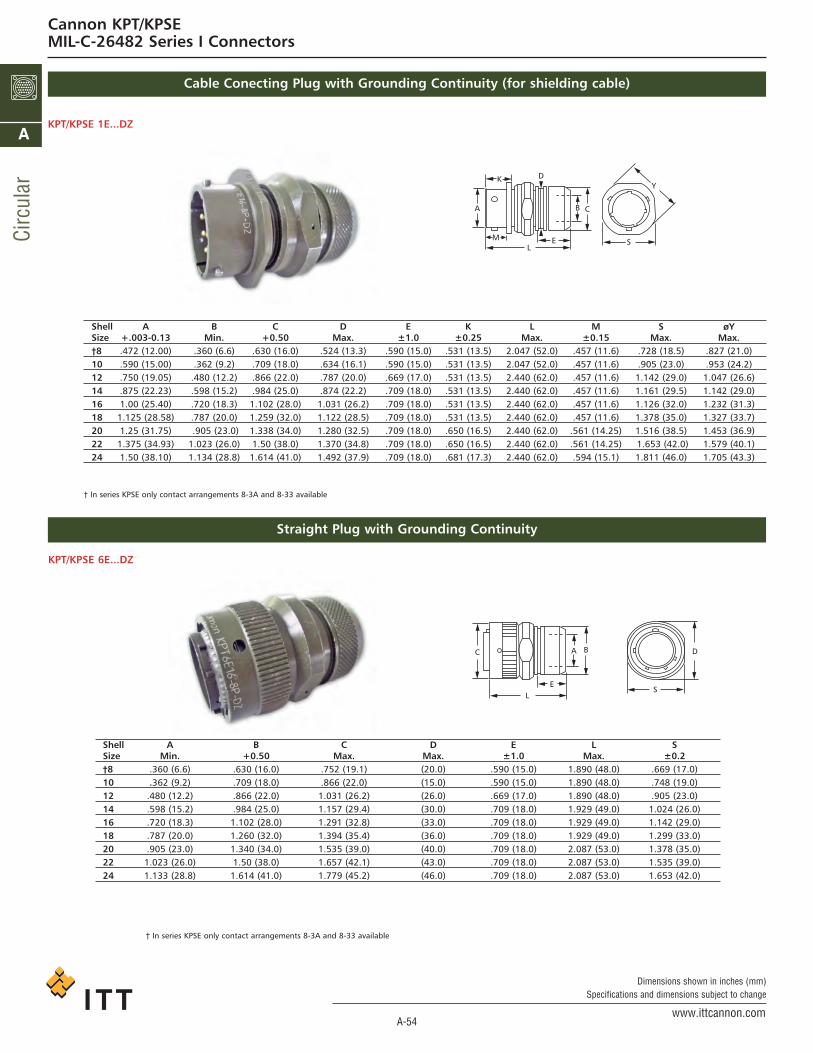
Cable Conecting Plug with Grounding Continuity (for shielding cable)
KPT/KPSE 1E...DZ
† In series KPSE only contact arrangements 8-3A and 8-33 available
Shell A B C D E K L M S øYSize +.003-0.13 Min. +0.50 Max. ±1.0 ±0.25 Max. ±0.15 Max. Max.†8 .472 (12.00) .360 (6.6) .630 (16.0) .524 (13.3) .590 (15.0) .531 (13.5) 2.047 (52.0) .457 (11.6) .728 (18.5) .827 (21.0)10 .590 (15.00) .362 (9.2) .709 (18.0) .634 (16.1) .590 (15.0) .531 (13.5) 2.047 (52.0) .457 (11.6) .905 (23.0) .953 (24.2)12 .750 (19.05) .480 (12.2) .866 (22.0) .787 (20.0) .669 (17.0) .531 (13.5) 2.440 (62.0) .457 (11.6) 1.142 (29.0) 1.047 (26.6)14 .875 (22.23) .598 (15.2) .984 (25.0) .874 (22.2) .709 (18.0) .531 (13.5) 2.440 (62.0) .457 (11.6) 1.161 (29.5) 1.142 (29.0)16 1.00 (25.40) .720 (18.3) 1.102 (28.0) 1.031 (26.2) .709 (18.0) .531 (13.5) 2.440 (62.0) .457 (11.6) 1.126 (32.0) 1.232 (31.3)18 1.125 (28.58) .787 (20.0) 1.259 (32.0) 1.122 (28.5) .709 (18.0) .531 (13.5) 2.440 (62.0) .457 (11.6) 1.378 (35.0) 1.327 (33.7)20 1.25 (31.75) .905 (23.0) 1.338 (34.0) 1.280 (32.5) .709 (18.0) .650 (16.5) 2.440 (62.0) .561 (14.25) 1.516 (38.5) 1.453 (36.9)22 1.375 (34.93) 1.023 (26.0) 1.50 (38.0) 1.370 (34.8) .709 (18.0) .650 (16.5) 2.440 (62.0) .561 (14.25) 1.653 (42.0) 1.579 (40.1)24 1.50 (38.10) 1.134 (28.8) 1.614 (41.0) 1.492 (37.9) .709 (18.0) .681 (17.3) 2.440 (62.0) .594 (15.1) 1.811 (46.0) 1.705 (43.3)
L
D
E
CA
K
M
B
S
Y
Straight Plug with Grounding Continuity
KPT/KPSE 6E...DZ
Shell A B C D E L SSize Min. +0.50 Max. Max. ±1.0 Max. ±0.2†8 .360 (6.6) .630 (16.0) .752 (19.1) (20.0) .590 (15.0) 1.890 (48.0) .669 (17.0)10 .362 (9.2) .709 (18.0) .866 (22.0) (15.0) .590 (15.0) 1.890 (48.0) .748 (19.0)12 .480 (12.2) .866 (22.0) 1.031 (26.2) (26.0) .669 (17.0) 1.890 (48.0) .905 (23.0)14 .598 (15.2) .984 (25.0) 1.157 (29.4) (30.0) .709 (18.0) 1.929 (49.0) 1.024 (26.0)16 .720 (18.3) 1.102 (28.0) 1.291 (32.8) (33.0) .709 (18.0) 1.929 (49.0) 1.142 (29.0)18 .787 (20.0) 1.260 (32.0) 1.394 (35.4) (36.0) .709 (18.0) 1.929 (49.0) 1.299 (33.0)20 .905 (23.0) 1.340 (34.0) 1.535 (39.0) (40.0) .709 (18.0) 2.087 (53.0) 1.378 (35.0)22 1.023 (26.0) 1.50 (38.0) 1.657 (42.1) (43.0) .709 (18.0) 2.087 (53.0) 1.535 (39.0)24 1.133 (28.8) 1.614 (41.0) 1.779 (45.2) (46.0) .709 (18.0) 2.087 (53.0) 1.653 (42.0)
† In series KPSE only contact arrangements 8-3A and 8-33 available
D
LE
C
S
BA
Cannon KPT/KPSEMIL-C-26482 Series I Connectors
ca_A1-A163.qxd:Layout 1 2/9/11 7:49 PM Page 54

A-55www.ittcannon.com
Dimensions shown in inches (mm)Specifications and dimensions subject to change
Circular
A
Wiring Instructions
Jam Nut Receptacle with Grounding Continuity (for shielded cable)
KPT/KPSE ...DZ
Cannon KPT/KPSEMIL-C-26482 Series I Connectors
KPT/KPSE 7E...DZ
Shell øA øB øC D E L S TSize Min. +0.5 Max. Max. 1.0 Max. ±0.25 ±0.25†8 .360 (6.6) .630 (16.0) .716 (18.2) .524 (13.3) .590 (15.0) 1.850 (47.0) .905 (23.0) .748 (19.0)10 .362 (9.2) .709 (18.0) .842 (21.4) .634 (16.1) .590 (15.0) 1.850 (47.0) 1.063 (27.0) .874 (22.2)12 .480 (12.2) .866 (22.0) .968 (24.6) .787 (20.0) .669 (17.0) 1.929 (49.0) 1.248 (31.7) 1.063 (27.0)14 .598 (15.2) .984 (25.0) 1.094 (27.8) .874 (22.2) .709 (18.0) 1.968 (50.0) 1.374 (34.9) 1.089 (30.2)16 .720 (18.3) 1.102 (28.0) 1.216 (30.9) 1.031 (26.2) .709 (18.0) 1.968 (50.0) 1.50 (38.1) 1.311 (33.3)18 .787 (20.0) 1.260 (32.0) 1.342 (34.1) 1.222 (28.5) .709 (18.0) 1.968 (50.0) 1.626 (41.3) 1.437 (36.5)20 .905 (23.0) 1.340 (34.0) 1.50 (38.1) 1.279 (32.5) .709 (18.0) 2.165 (55.0) 1.811 (46.0) 1.563 (39.7)22 1.023 (26.0) 1.50 (38.0) 1.626 (41.3) 1.370 (34.8) .709 (18.0) 2.165 (55.0) 1.937 (49.2) 1.689 (42.9)24 1.133 (28.8) 1.614 (41.0) 1.748 (44.4) 1.492 (37.9) .709 (18.0) 2.165 (55.0) 2.059 (52.3) 1.811 (46.0)
† In series KPSE only contact arrangements 8-3A and 8-33 available
B CA
D
EL
S
L
Fixing of shielding braid to connectors withDZ-adapter
• Loosen lock nut (5). Slide heat shrink component(6) and lock nut (5) over cable.
• Push shielding braid (7) onto endbell (3) and overthread (2).
• Fasten shielding braid (7) into rounded groove bymeans of bailing wire
• Fold back protruding shielding braid on cone.
• Slide lock nut (5) onto endbell (3). The foldedback shielding braid protrudes under the tightened lock nut.
• Shrink heat shrink component (6) according tomanufacturer’s instructions. (End of heat shrinkcomponent to be located in square groove (1)).
ca_A1-A163.qxd:Layout 1 2/9/11 7:49 PM Page 55

A-56www.ittcannon.com
Dimensions shown in inches (mm)Specifications and dimensions subject to change
Circ
ular
A
Panel Cutouts
FLANGE (FRONT MOUNTING) MOUNTING HOLE DIA.KPT/KPSE
Shell KPT/KPSESize A Dia. R P ±.005 Screw
†8 .618 (15.70) .594 (15.09) .125 (3.17) #4
10 .735 (16.67) .719 (18.26) .125 (3.17) #4
12 .859 (21.82) .812 (20.62) .125 (3.17) #4
14 .985 (25.02) .906 (23.01) .125 (3.17) #4
16 1.113 (28.27) .969 (24.61) .125 (3.17) #4
18 1.235 (31.37) 1.062 (26.97) .125 (3.17) #4
20 1.361 (34.57) 1.156 (29.36) .125 (3.17) #4
22 1.485 (37.72) 1.250 (31.75) .125 (3.17) #4
24 1.611 (40.92) 1.375 (34.92) .155 (3.94) #6
† Not available in KPSE connectors. Shell KPT/KPSESize A B†8 .578 (14.68) .540 (13.72)10 .703 (17.86) .665 (16.89)12 .890 (22.61) .828 (21.02)14 1.015 (25.78) .952 (24.18)16 1.140 (28.96) 1.076 (27.33) 18 1.265 (32.13) 1.201 (30.51)20 1.390 (35.31) 1.326 (33.68)22 1.515 (38.48) 1.451 (36.86)24 1.640 (41.66) 1.576 (40.03)
† Not available in KPSE connectors.
Box and Wall Mounting Receptacle
Jam Nut Receptacle
R (T.P.)
A +.010 (0.25)-.000 (0.00)
P±.005 (013) 4 HOLES
A +.010 (0.25)-.000 (0.00)
B +.000 (0.00)-.010 (0.25)
Panel Thickness
Size8
1012141618202224
Wall Mounting and Box Mounting Receptacle
Thru-Bulkhead ReceptacleMaximum panel thickness dimensions allowable toensure complete connector operation for the the WallMounting Receptacle, Box Mounting Receptacle, andThru-Bulkhead Receptacle.
BMax.
.087(2.21)
.212(5.38)
Size81012141618202224
BMax.paneland
screwhead
.218(5.54)
.311(7.90)
.334(8.74)
Cannon KPT/KPSEMIL-C-26482 Series I Connectors
B
FRONT PANELMTG REF
REAR PANELMTG REF
FRONT PANELMTG REF
REAR PANELMTG REF
BB B
PANEL
PANEL
PANEL
PANEL
ca_A1-A163.qxd:Layout 1 2/9/11 7:49 PM Page 56

A-57www.ittcannon.com
Dimensions shown in inches (mm)Specifications and dimensions subject to change
Circular
A
MIL-C-26482 Specifications
The following excerpts are some of the paremeter requirements of the MIL-C-26482 specification.
Test ParagraphDescription Reference Requirements
Contact 4.6.32.1Retention
Contact 4.6.11Insertion/Extraction(KPSE only)Coupling 4.6.3Torque
Durability 4.6.17
Insert Retention 4.6.29
Insulation Resistance 4.6.7.1
Vibration 4.6.21
Shock 4.6.23
Thermal 4.6.12Shock
Humidity 4.6.25
Air Leakage 4.6.15.1(KPT Only)
Salt Spray 4.6.19(Corrosion)
Fluid Immersion 4.6.27
After preloading to 3 pounds maximum, the force shall be applied at a rate of approximately 1 pound per second and maintained at full load for 5-10 seconds.. No damage to contacts or insert shall result nor shall the contacts be dislocatedfrom their normal position in the connector more that 0.012 inch under giveload for KPSE and within 1 minute after the load is removed for KPT.
Contact Size 20 16 12Load in Pounds Min. 15 25 25Load in KG Min. 6.8 11.3 11.3
When using the proper insertion and extraction tools the forces required to insert or extract the contact shall not exceed 20Lbs. Connectors shall be less endbell.
For qualification testing, mating halves shall be coupled and uncoupled, measuring the torques necessary. The torquesrequired to couple and uncouple mating connectors halves shall fall within the limits specified as follows:
Torque in lb (NM) Torque in lb. (NM)Shell Size Max Min. Shell Size Max Min
8 8 (.90) 1 (.11) 18 28 (3.16) 4 (.45)10 12 (1.36) 1 (.11) 20 32 (3.62) 6 (.68)12 16 (1.81) 2 (.23) 22 36 (4.07) 7 (.79)14 20 (2.26) 4 (.45) 24 44 (4.97) 7 (.79)16 24 (2.71) 4 (.45)
Connector halves shall be mated and unmated 500 times at a rate of 200 ± 100 cycles per hour. The test may be performedby hand or by mechanical means, but the coupling ring shall be operated as in normal service. Failure to complete this testbecause of mechanical malfunction shall be cause for rejection.
Connectors with the endbells and gromments (if possible) removed shall be subjected to a 75 psi load on the insulator inboth directions. The load shall be applied at a rate of 10lb/sec. and held for 5 to 10 secs. Insulators shall not be dislodgedfrom their original position.
On unmated connectors at 25ºC ±3ºC a potential of 500 VDC ±10% shall be applied between all, but not more than 6, pairsof adjacent contacts and between all, but not more than 6, contacts and the shell. Failure to meet a minimum requirementof 5,000 megohms shall be cause for rejection.
Wired, mated connectors shall be subjected to the vibration test of MIL-STD-1344, Method 205, Test Condition II. Receptaclesshall be mounted on the vibration fixture by normal means. All contacts shall be wired in a series circuit and 100 max. mil-liamperes of current shall be allowed to flow through the series circuit during vibration. Suitable means shall be employed tomonitor the current flow and to indicate any discontinuity of more than 10 microseconds. The wire bundle shall be clampedto nonvibrating points at least 8 inches from the rear of the connector. Current discontinuity of 10 microsecond or more, dis-engagement of the mated connectors, evidence of cracking, breaking, or loosening of parts shall be cause for rejection.
Wired, mated connectors shall be subject to one shock in each direction in each of three mutually perpendicular axes. Thepulse shall be approximate half sine wave of 50g±15% magnitude with a duration of 11 ± 1 milliseconds. Receptacles shallbe mounted on a shock fixture by normal means. All contacts shall be wired in a series circuit and 90-110 ma. of currentshall flow through the series circuit during shock. Suitable means shall be employed to monitor the current flow and to indi-cate any discontinuity of more than 10 microseconds. Current discontinuity of 10 microseconds or more, disengagement ofthe mated connectors, evidence of cracking, breaking, or loosening of parts shall be cause for rejection.
Wired, unmated plug and receptacle shall be subjected to 5 cycles of hot and cold temperatures. Maximum temperatureshall be +125ºC and the minimum shall be -55ºC. The temperature extreme shall be 1/2 hour minimum. Cracking, breakingor loosening of parts shall be cause for rejection.
The connectors shall be subjected to varying humididity, 50% to 95%, conditions for a period of 10 days KRSE or 20 daysKPT. The insulation resistance shall not be less than 100 megohms.
A 30 psi pressure differential shall be applied across the connector for 30 minutes. The leak rate, in either direction, shall be
no greater than 1 atmosphere cubic inch per hour (4,55 X 10 -3 cm3/S) at -67ºF (-55ºC).
Unmated and wired connectors shall be subject to a salt fog for 48 hours. These shall be no exposure of base metal, the con-nector shall be functional and meet the contact resistance requirement.
At least one connector, unmated and wired, shall he immersed in each fluid for a period of 20 hours then dried for an hour.Connectors shall be able to make and meet the coupling torque requirements. a) Hydraulic Fluid per MIL-H-5606, b)Lubricating Oil per MIL-L-7808
Cannon KPT/KPSEMIL-C-26482 Series I Connectors
ca_A1-A163.qxd:Layout 1 2/9/11 7:49 PM Page 57

A-58www.ittcannon.com
Dimensions shown in inches (mm)Specifications and dimensions subject to change
Circ
ular
A
Cannon KPT/KPSEMIL-C-26482 Series I Connectors
M22520/1-01 CRINP TOOLM22520/01-02 Turret
CBT-520/530
KPSE Insertion
#20
KPSE Extraction
Contact Size20 MS24256A2016 MS24256A16
Contact Military Color Bands ITT CannonSize/Type Part Number 1st 2nd 3rd Part Number20 Socket M39029/32-259 Red Green White 980-0008-992
20 Pin M39029/31-240 Red Yellow Black 030-9036-00016 Socket M39029/32-247 Red Yellow Violet 031-9095-003
16 Pin M39029/31-228 Red Red Grey 030-9032-003
Contact Part Number ColorSize Cannon Military Code20 225-1012-000 MS3187A20 Red16 225-1011-000 MS3187-16 Blue
Contact Size20 MS24256R2016 MS24256R16
Tooling Crimp
Tooling Insertion/Extraction
Contacts
Wire Hole Fillers/Grommets Sealing Plugs
ca_A1-A163.qxd:Layout 1 2/9/11 7:49 PM Page 58

A-59www.ittcannon.com
Dimensions shown in inches (mm)Specifications and dimensions subject to change
Circular
A
Cannon KPT/KPSEMIL-C-26482 Series I Connectors
KPSE Assembly Instructions
WireContact Size Strip
Size AWG mm2 Insulation mm20 #20-#24 .5 - .2 3/16” 4.76
16 #16-#20 1.3 - .5 1/4” 6.35
Size Torque in-lb (NM)8, 10, 12 and 14 10-15 (1.23-1.69)
16 and18 15-25 (1.69-2.82)20, 22 and 24 25-35 (2.82-3.95)
CRIMPING CONTACTS1. Strip wires according to the table above taking carenot to cut or nick strands.
CONTACT INSERTION1. Remove hardware from plug and receptacle. Slidehardware overwire bundle in proper order forreassembly.
COMPLETION4. Check face of plug or receptacle for proper contact installation.
CONTACT EXTRACTION1. Slide hardware back over wire bundle. Using properextraction tool or extraction end of proper inser-tion/extraction tool, proceed as follows:
2. Inserts stripped wire into contact crimp pot. Wire must be visi-ble thru inspection hole.
3. Using correct tool and locator select proper crimp setting forwire sizer to be crimped; cycle the tool once to be sure the inden-tors are open. Insert contact and wire into locator. Squeeze toolhandles firmly and completely to insure a proper crimp. The toolwill not release unless the crimp indentors in the tool head havebeen fully actuated. Release crimped contact and wire from tool.Be certain the wire is visible thru inspection hole in contact.CAUTION: Check that none of the contacts are bent or damagedin any way after crimping.
2. Use the proper contact insertion tool and slide the tool overthe terminal end of the contact. The size 16 contact lies in thetool and the tool tip butts against the contact shoulder. The rear,or insulation support of the size 20 contact butts against aninternal shoulder in the tool tip.NOTE: Apply a small amount of isopropl alcohol to the insertiontool tip while installing contacts.
3. Beginning from center cavity and working outwards in a cir-cular pattern, insert wired contacts into rear of connector byhand untill the front of the contact shoulder is no more than1/8” from the grommet. Holding the connector horizontally,position tool behind contact. Push tool straight into contactcavity untill contact snaps into position. A light pull on wire willassure that contact is locked securely. Repeat for remaining con-tacts.
4. Use contacts and grommet sealing plugs to fill anyempty cavities.
KPSE: There are two lines on the clip sleeve which are vital to theremoval process. The first index line is used for removing pin con-tacts while the second index line is for removing socket contacts.
Carefully place the tool tip over the contact to be extracted untilthe tool tip touches the insulator face. Carefully rotate the tooluntil the index line is slightly below the insulator face. Keep aneven pressure against the tool body; push plunger forward withthumb and index finger, and push the contact out through theclip. Carefully remove extraction tool from connector. Pull wireby hand to complete the removal of the contact.
2. Using mating connector with contacts installed, mate bothconnector halves together.
3. Assemble Ferrule over the grommet by hand as far as possi-ble.
4. Assemble endbell over ferrule and loosely tighten endbell.Partially loosen (1/4 turn) and retighten to recommended torquelimits.
2nd Index LineSocket Contacts
1st Index LinePin Contacts
ca_A1-A163.qxd:Layout 1 2/9/11 7:49 PM Page 59

A-60www.ittcannon.com
Dimensions shown in inches (mm)Specifications and dimensions subject to change
Circ
ular
A
Cannon KPT/KPSEMIL-C-26482 Series I Connectors
How to Order - Special Termination Connectors
PREFIX
KPT
KPT
KPT
KPSE
KPSE
KPSE
03
04
05
03
04
05
18
18
18
18
18
18
P
P
P
P
P
P
W
W
W
W
W
W
32
32
32
32
32
32
-
-
-
-
-
-
-
-
-
-
-
-
SHELL STYLE
SHELL SIZE
CONTACT ARRANGEMENT
CONTACT TYPE
ALTERNATE INSERT POSITION
Contact ITT Cannon for additional Information
P - PIN
S - Socket
DASH (No Class required, less
rear termination)
Solder Type KPT03/04/05 - Supplied less endball, ferrule and grommet.
KPT03 KPT04 KPT05
Crimp Type KPSE03/04/05 - Supplied less endball, ferrule.
Twist Pull Lanyard Release Coupler Plug
KPSE03
KPT06/KPSE06
KPSE04 KPSE05
KPT
KPSE
6
6
A
E
22
22
55
55
P
S
W
Z
16
16
-
-
PREFIX
SHELL STYLE
SERVICE TYPE
SHELL SIZE
CONTACT ARRANGEMENT
CONTACT TYPE
POLARIZATION
MODIFICATION CODE*
*Omit (0) of shell style indication when using this modification code.
16 = Overall length of connector including lanyard to be 6.0 (152.40) +_ .125 (3.18) when measured
over a 1.0 (25.40) +_ .005 (0.13) diameter mandrel.
ca_A1-A163.qxd:Layout 1 2/9/11 7:49 PM Page 60

A-61www.ittcannon.com
Dimensions shown in inches (mm)Specifications and dimensions subject to change
Circular
A
Cannon KPT/KPSEMIL-C-26482 Series I Connectors
Cross Reference List KPT/MIL-C-26482, VG 95328
Cross Reference List List Protective Caps
Part No. KPT Part No. Part No.ITT Cannon MIL-26482 VG 95328KPT00B*-***KPT00B*-***KPT00E*-*** MS3110E*-***KPT00F*-*** MS3110F*-***KPT00G*-***KPT00J*-*** MS3110J*-***KPT00P*-*** MS3110P*-***KPT0E*-***DNKPT0E*-***DZKPT01A*-***KPT01B*-***KPT01E*-*** MS3111E*-***KPT01F*-*** MS3111F*-***KPT01G*-***KPT01J*-*** MS3111J*-***KPT01P*-*** MS3111P*-***KPT1E*-***DNKPT06A*-***KPT06B*-***KPT06E*-*** MS3116E*-***KPT06F*-*** MS3116F*-***KPT06G*-***KPT1E*-***DZ
KPT06J*-*** MS3116J*-***KPT06P*-*** MS3116P*-***KPT6A*-***88KPT6E*-***DNKPT6E*-***DZKPT02E*-*** MS3112E*-*** H*-***VG 95328KPT07A*-***KPT07E*-*** MS3114E*-***KPT07F*-*** MS3114F*-***KPT08E*-***KPT08F*-***KPT08P*-***KPT7E*-***DNKPTB*-*** MS3119E*-***
Part No. Part No. Part No.ITT Cannon MIL-26482 VG 95328KPT80 MS 3180KPT80...C MS 3180...C Z 2...VG 95328KPT81 MS 3181KPT81...C MS 3181...C Z 1...VG 95328KPT81...N MS 3181...N
ca_A1-A163.qxd:Layout 1 2/9/11 7:49 PM Page 61

A-62www.ittcannon.com
Dimensions shown in inches (mm)Specifications and dimensions subject to change
Circ
ular
A
Cannon KPT/KPSEMIL-C-26482 Series I Connectors
Cross Reference List KPSE/MIL-C-26482, VG 95328
Part No. KPSE Part No. Part No.ITT Cannon MIL-C-26482 VG 95328KPSE00A*-***KPSE00B*-***KPSE00E*-*** MS3120E*-*** A*-***VG 95328KPSE00F*-*** MS3120F*-*** B*-***VG 95328KPSE0E*-***DZ R*-***VG 95328KPSE00J*-***KPSE00P*-*** MS3120P*-***KPSE0E*-***DNKPSE00G*-***KPSE01A*-*** 25101RA*-***50KPSE01B*-***KPSE01E*-*** MS3121E*-***KPSE01F*-*** MS3121F*-***KPSE01G*-***KPSE01J*-***KPSE01P*-*** MS3121P*-***KPSE*-***DNKPSE02E*-*** MS3122E*-*** C*-***VG 95328KPSE06A*-***KPSE06B*-***KPSE06E*-*** MS3126E*-***KPSE06F*-*** MS3126F*-*** K*-***VG 95328KPSE06G*-***KPSE06J*-***KPSE06P*-*** MS3126P*-***KPSE6A*-***88KPSE6E*-***88 N*-***VG 95328KPSE6E*-***DN J*-***VG 95328KPSE6E*-***DZ M*-***VG 95328KPSE07A*-***KPSE1E*-***DZKPSE7E*-***DN S*-***VG 95328KPSE07E*-*** MS3124E*-*** D*-***VG 95328KPSE07F*-*** MS3124F*-*** E*-***VG 95328KPSE08E*-***KPSE08F*-***KPSE08P*-***KPSE7E*-***DZ T*-***VG 95328
ca_A1-A163.qxd:Layout 1 2/9/11 7:49 PM Page 62