C9i, C7i Exercise Bikesecx.images-amazon.com/images/I/A1NOzHVaVwS.pdf · Congratulations... and...
8
C9i, C7i Exercise Bikes Assembly Instructions
-
Upload
truongkiet -
Category
Documents
-
view
221 -
download
3
Transcript of C9i, C7i Exercise Bikesecx.images-amazon.com/images/I/A1NOzHVaVwS.pdf · Congratulations... and...

C9i, C7i Exercise BikesAssembly Instructions

Congratulations...
and welcome to the world of Life Fitnessand the Life Fitness C9i & C7i Exercise Bikes.
The following Parts Identification Listing and the step by step assemblyprocedures have been assembled to make the set-up of the Exercise Bikes asquick and easy as possible.
Please take special note of the following important points prior to choosing alocation and beginning assembly of the Exercise Bikes.

IMPORTANT SAFETY INSTRUCTIONS! ⇒ DO NOT locate the Exercise Bike outdoors, near swimming pools, or in areas of high humidity. ⇒ DO NOT operate your Exercise Bike if it has been dropped, damaged, or even partially immersed
in water. Contact Life Fitness Customer Support Services at the number in the Operation Manual. ⇒ DO NOT locate the Exercise Bike any closer than 30 inches ( 76 cm ) to a television set. ⇒ DO NOT locate additional Exercise Bike any closer than a minimum of 42 inches (107 cm) from
center to center to avoid interference (cross talk) between Heart Rate monitors. ⇒ DO keep the area around your Exercise Bike clear of any obstructions, including walls and furniture. ⇒ DO verify the contents of the delivery carton against the accompanying Parts Listing prior to setting
the cartons and shipping material aside. If any parts are missing, contact Life Fitness CustomerSupport Services at the number listed in the Operation Manual. Save the shipping cartons in case ofreturn.
⇒ DO read the entire Operation Manual prior to attempting to operate this machine as this is essential
for proper use.
⇒ NE PAS placer le vélo d’exercice allongé Lifecycle à l’extérieur, près d’une piscine ou dans unendroit très humide.
⇒ NE PAS faire fonctionner le vélo d’exercice allongé Lifecycle s’il est tombé, s’il a été endommagé ou
s’il a été partiellement plongé dans l’eau. Téléphoner au service après-vente de Life Fitness dont lenuméro figure sur la couverture arrière du guide d’installation.
⇒ NE PAS placer le vélo d’exercice allongé Lifecycle à moins de 76 cm (30 po) d’un poste de
télévision. ⇒ MAINTENIR la zone autour du vélo d’exercice allongé Lifecycle libre de toute obstruction, y compris
murs et meubles.
⇒ VÉRIFIER si l’emballage contient toutes les pièces de la liste jointe avant de le mettre de côté. Si despièces manquent, téléphoner au service après-vente de Life Fitness dont le numéro figure sur lacouverture arrière du guide d’installation. Conserver l’emballage au cas où l’appareil devrait êtrerenvoyé.
⇒ LIRE le manuel de l’utilisateur tout entier avant d’essayer de faire fonctionner cet appareil. Ceci est
indispensable à son utilisation correcte.
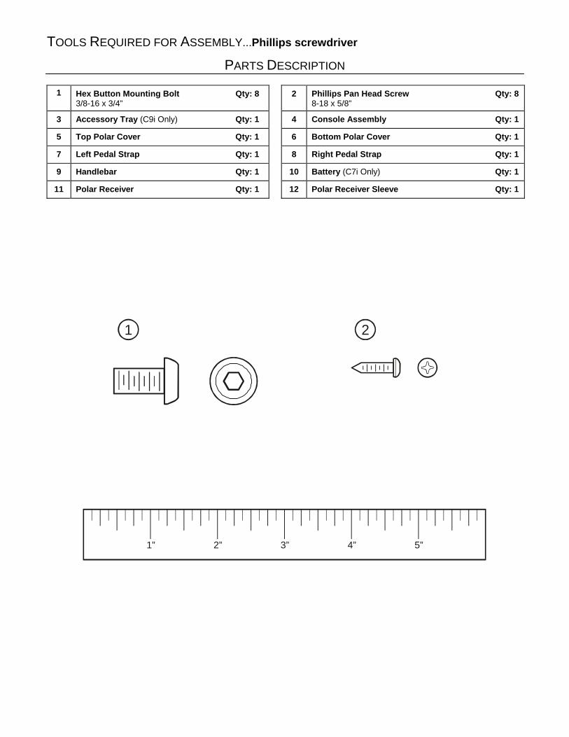
TOOLS REQUIRED FOR ASSEMBLY...Phillips screwdriver
PARTS DESCRIPTION
1 Hex Button Mounting Bolt Qty: 83/8-16 x 3/4”
2 Phillips Pan Head Screw Qty: 88-18 x 5/8”
3 Accessory Tray (C9i Only) Qty: 1 4 Console Assembly Qty: 1
5 Top Polar Cover Qty: 1 6 Bottom Polar Cover Qty: 1
7 Left Pedal Strap Qty: 1 8 Right Pedal Strap Qty: 1
9 Handlebar Qty: 1 10 Battery (C7i Only) Qty: 1
11 Polar Receiver Qty: 1 12 Polar Receiver Sleeve Qty: 1
1” 2” 3” 4” 5”
1 2

5
9
6
3
2
4
1
1
10
22
8
7
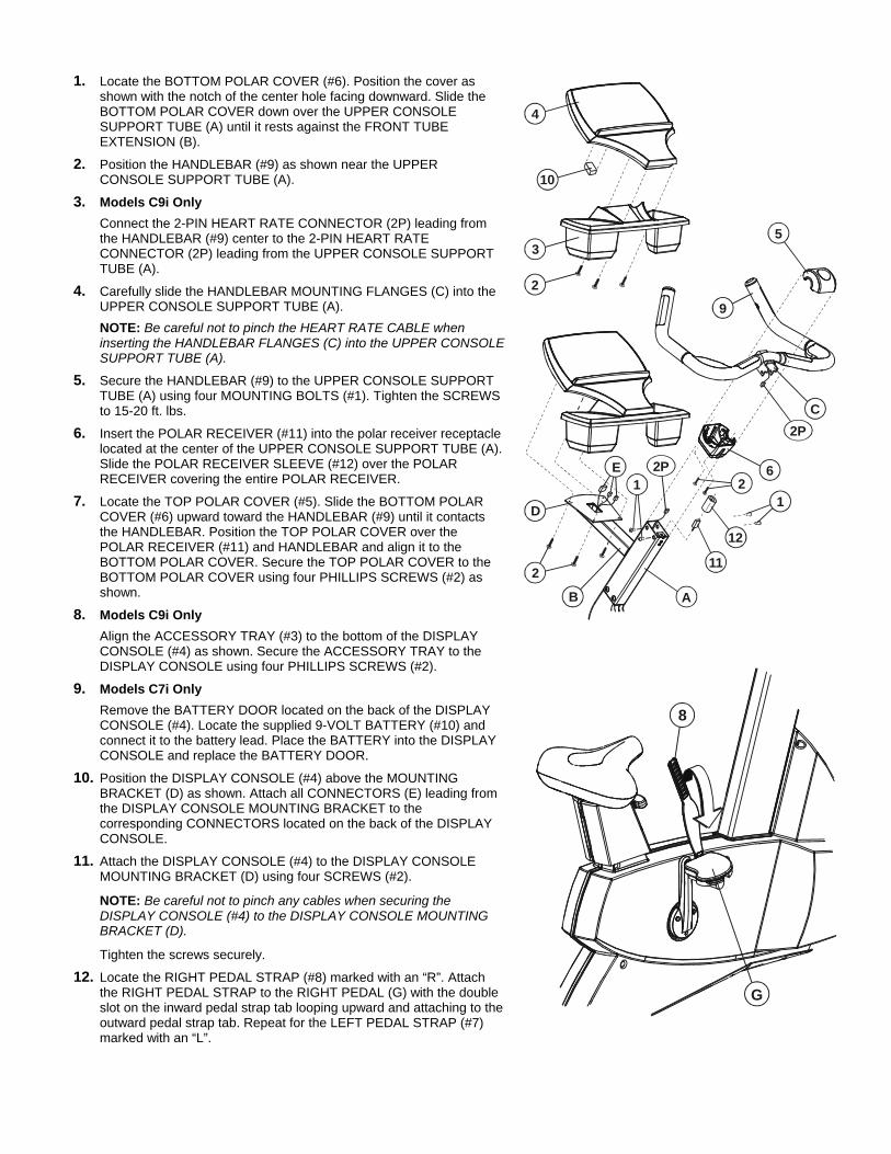
1. Locate the BOTTOM POLAR COVER (#6). Position the cover asshown with the notch of the center hole facing downward. Slide theBOTTOM POLAR COVER down over the UPPER CONSOLESUPPORT TUBE (A) until it rests against the FRONT TUBEEXTENSION (B).
2. Position the HANDLEBAR (#9) as shown near the UPPERCONSOLE SUPPORT TUBE (A).
3. Models C9i OnlyConnect the 2-PIN HEART RATE CONNECTOR (2P) leading fromthe HANDLEBAR (#9) center to the 2-PIN HEART RATECONNECTOR (2P) leading from the UPPER CONSOLE SUPPORTTUBE (A).
4. Carefully slide the HANDLEBAR MOUNTING FLANGES (C) into theUPPER CONSOLE SUPPORT TUBE (A).NOTE: Be careful not to pinch the HEART RATE CABLE wheninserting the HANDLEBAR FLANGES (C) into the UPPER CONSOLESUPPORT TUBE (A).
5. Secure the HANDLEBAR (#9) to the UPPER CONSOLE SUPPORTTUBE (A) using four MOUNTING BOLTS (#1). Tighten the SCREWSto 15-20 ft. lbs.
6. Insert the POLAR RECEIVER (#11) into the polar receiver receptaclelocated at the center of the UPPER CONSOLE SUPPORT TUBE (A).Slide the POLAR RECEIVER SLEEVE (#12) over the POLARRECEIVER covering the entire POLAR RECEIVER.
7. Locate the TOP POLAR COVER (#5). Slide the BOTTOM POLARCOVER (#6) upward toward the HANDLEBAR (#9) until it contactsthe HANDLEBAR. Position the TOP POLAR COVER over thePOLAR RECEIVER (#11) and HANDLEBAR and align it to theBOTTOM POLAR COVER. Secure the TOP POLAR COVER to theBOTTOM POLAR COVER using four PHILLIPS SCREWS (#2) asshown.
8. Models C9i OnlyAlign the ACCESSORY TRAY (#3) to the bottom of the DISPLAYCONSOLE (#4) as shown. Secure the ACCESSORY TRAY to theDISPLAY CONSOLE using four PHILLIPS SCREWS (#2).
9. Models C7i OnlyRemove the BATTERY DOOR located on the back of the DISPLAYCONSOLE (#4). Locate the supplied 9-VOLT BATTERY (#10) andconnect it to the battery lead. Place the BATTERY into the DISPLAYCONSOLE and replace the BATTERY DOOR.
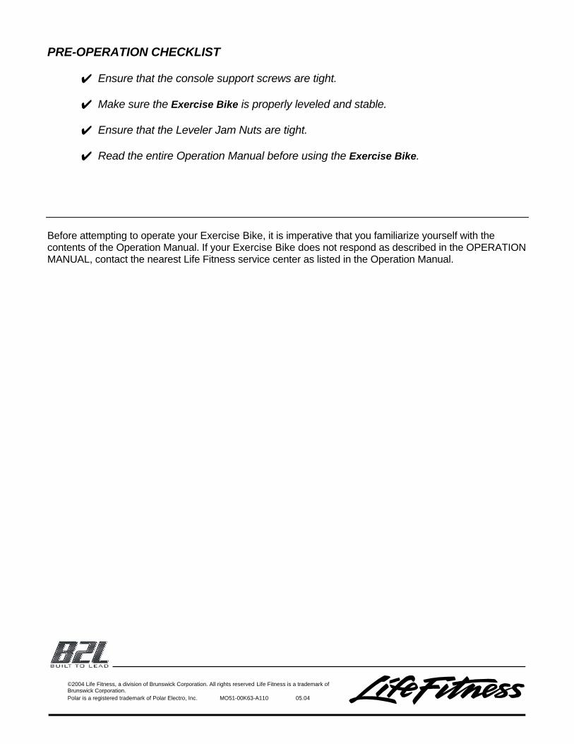
10. Position the DISPLAY CONSOLE (#4) above the MOUNTINGBRACKET (D) as shown. Attach all CONNECTORS (E) leading fromthe DISPLAY CONSOLE MOUNTING BRACKET to thecorresponding CONNECTORS located on the back of the DISPLAYCONSOLE.
11. Attach the DISPLAY CONSOLE (#4) to the DISPLAY CONSOLEMOUNTING BRACKET (D) using four SCREWS (#2).
NOTE: Be careful not to pinch any cables when securing theDISPLAY CONSOLE (#4) to the DISPLAY CONSOLE MOUNTINGBRACKET (D).
Tighten the screws securely.
12. Locate the RIGHT PEDAL STRAP (#8) marked with an “R”. Attachthe RIGHT PEDAL STRAP to the RIGHT PEDAL (G) with the doubleslot on the inward pedal strap tab looping upward and attaching to theoutward pedal strap tab. Repeat for the LEFT PEDAL STRAP (#7)marked with an “L”.
2
3
4
2
12
6
C
5
11
A
2P
2P
D
E
9
B
11
10
2
8
G

PRE-OPERATION CHECKLIST
! Ensure that the console support screws are tight. ! Make sure the Exercise Bike is properly leveled and stable.
! Ensure that the Leveler Jam Nuts are tight. ! Read the entire Operation Manual before using the Exercise Bike.
Before attempting to operate your Exercise Bike, it is imperative that you familiarize yourself with thecontents of the Operation Manual. If your Exercise Bike does not respond as described in the OPERATIONMANUAL, contact the nearest Life Fitness service center as listed in the Operation Manual.
©2004 Life Fitness, a division of Brunswick Corporation. All rights reserved Life Fitness is a trademark ofBrunswick Corporation.Polar is a registered trademark of Polar Electro, Inc. MO51-00K63-A110 05.04