C48T cover-D C48TTOCgreen.QXD 6/9/2017 9:41 AM Page 1 THE ...
44
THE 1/16 DIN TIMER MODEL C48T INSTRUCTION MANUAL
Transcript of C48T cover-D C48TTOCgreen.QXD 6/9/2017 9:41 AM Page 1 THE ...

THE 1/16 DIN TIMER
MODEL C48T INSTRUCTION MANUAL
C48T cover-D_C48TTOCgreen.QXD 6/9/2017 9:41 AM Page 1

INTRODUCTIONThe C48 Timers (C48T) are a multi-purpose series of industrial controlproducts that are field-programmable for solving various applications. Thisseries of products is built around the concept that the end user has thecapability to program different functions into the unit in order to adapt todifferent indication and control requirements.
The C48T unit, which you have purchased, has the same high qualityworkmanship and advanced technological capabilities that have made RedLion Controls the leader in today’s industrial market.
Red Lion Controls has a complete line of industrial indication and controlequipment, and we look forward to servicing you now and in the future.
CAUTION:Read complete instructions prior toinstallation and operation of the unit.
CAUTION: Risk of electric shock.
UL Recognized Component,File #E137808
C48T cover-D_C48TTOCgreen.QXD 6/9/2017 9:41 AM Page 2

TABLE OF CONTENTS
GENERAL DESCRIPTION.............................................................................................................................................................1Safety Summary.......................................................................................................................................................................1Block Diagram..........................................................................................................................................................................2
INSTALLATION & CONNECTIONS...............................................................................................................................................3Multiple Unit Stacking ..............................................................................................................................................................3Mounting Instructions ...............................................................................................................................................................4Unit Removal Procedure ..........................................................................................................................................................4Removing Unit Assembly ........................................................................................................................................................4Installing Unit Assembly ...........................................................................................................................................................4Output Board ...........................................................................................................................................................................5
Replacing Relay Output Board .........................................................................................................................................5EMC Installation Guidelines ....................................................................................................................................................6Wiring Connections .................................................................................................................................................................6
AC Versions (C48TXX0X)..................................................................................................................................................7DC Versions (C48TXX1X) .................................................................................................................................................7Serial Communications Wiring...........................................................................................................................................7
Run/Stop Input..........................................................................................................................................................................7User Input Plug Jumper ...........................................................................................................................................................8Output Wiring ...........................................................................................................................................................................8Program Disable Plug Jumper .................................................................................................................................................8
FRONT PANEL DESCRIPTION .....................................................................................................................................................9Keypad Functions.....................................................................................................................................................................9
BASIC OPERATION.....................................................................................................................................................................10Normal Operating Mode.........................................................................................................................................................10Modifying A Secondary Display Parameter From the Front Panel ........................................................................................10Protected Value Menu ...........................................................................................................................................................10Front Panel Accessible Functions With Program Disable .....................................................................................................11
PROGRAMMING GENERAL DESCRIPTION .............................................................................................................................12Programming Option Values ..................................................................................................................................................12Programming Numeric Data Values.......................................................................................................................................12
Digit Entry ........................................................................................................................................................................12Auto Scrolling...................................................................................................................................................................12
-i-

TABLE OF CONTENTS (Cont’d)
USER INTERFACE/PROGRAMMING MODES ...........................................................................................................................13Programming Menu................................................................................................................................................................13
Numeric Value Entry Method ...........................................................................................................................................13Timer Range ....................................................................................................................................................................13Timer Operating Mode.....................................................................................................................................................13Timer Reset at Power-up.................................................................................................................................................17Access Preset Values ......................................................................................................................................................17Preset 1 Value .................................................................................................................................................................17Preset 2 Value (Dual Preset Model only) ........................................................................................................................17Preset 1 Track Preset 2 (Dual Preset Model only) ..........................................................................................................17Access Output Time Values.............................................................................................................................................18Output Resolution ............................................................................................................................................................18Output 1 Time Value ........................................................................................................................................................18Output 2 Time Value (Dual Preset Model only) ...............................................................................................................18Reverse Annunciator Logic..............................................................................................................................................19Output Power-Up State....................................................................................................................................................19User Inputs.......................................................................................................................................................................19User Input 1 .....................................................................................................................................................................20User Input 2 .....................................................................................................................................................................20User Input 3 .....................................................................................................................................................................20User F1 Key.....................................................................................................................................................................20Programming/Protected Parameter Menu Code (0-199).................................................................................................20Scroll Display ...................................................................................................................................................................20Serial Baud Rate and Parity Settings ..............................................................................................................................21Serial Unit Address (00-99) .............................................................................................................................................21Serial Abbreviate Mnemonics ..........................................................................................................................................21Print Options ....................................................................................................................................................................21Print and Reset Timer Value............................................................................................................................................22Factory Settings...............................................................................................................................................................22
Factory Settings Chart...............................................................................................................................................22User Settings Chart ...................................................................................................................................................23
-ii-

TABLE OF CONTENTS (Cont’d)
RS-485 SERIAL COMMUNICATIONS .........................................................................................................................................24Communication Format ..........................................................................................................................................................24Sending Commands And Data...............................................................................................................................................24Receiving Data .......................................................................................................................................................................26Serial Connections .................................................................................................................................................................27
Terminal Descriptions ......................................................................................................................................................27Troubleshooting Serial Communications................................................................................................................................27
Connecting To A Host Terminal........................................................................................................................................28APPENDIX “A” - APPLICATION EXAMPLE ..............................................................................................................................29APPENDIX “B” - SPECIFICATIONS AND DIMENSIONS ..........................................................................................................30APPENDIX “C” - TROUBLESHOOTING ....................................................................................................................................32APPENDIX “D” -TERMINAL CONFIGURATIONS FOR C48 TIMERS.......................................................................................34APPENDIX “E” - ORDERING INFORMATION ...........................................................................................................................35
-iii-

C48TTOCgreen.QXD 3/8/04 2:40 PM Page iv

GENERAL DESCRIPTIONThe Model C48 Timer is available in Single or Dual Preset models. The
C48T features a 7 segment, 2 line by 6 digit reflective or backlit LCD display.For the backlit versions, the main display line is red and shows the timer value.The smaller secondary display line is green and can be used to view the presetvalues or output time values.The C48 Timer can be configured for a variety of different operating modes
to meet most timing application requirements. Twelve timing ranges areavailable from thousandths of a second to hours and minutes. Decimal Pointsare used to separate the time units (hours, minutes, seconds). Timing can becumulative or can reset and start upon each power cycle. “On Delay” or “OffDelay”, “Single Shot”, and “Repetitive auto cycling” modes are all supported.Four front panel push-buttons are used for programming the operating modes
and data values, changing the viewed display, and performing userprogrammable functions, e.g. reset, etc. The C48T can be configured for one oftwo numeric data entry methods, digit entry or automatic scrolling. The digitentry method allows for the selection and incrementing of digits individually.The automatic scrolling method allows for the progressive change of onethrough all digit positions by pressing and holding the “up” or “down” button.The C48 Timer has a Run/Stop Input, 3 programmable User Inputs, and a
programmable front panel function key. The Run/Stop and User Inputs can beconfigured as sinking (active low) or sourcing (active high) inputs via a singleplug jumper. The following functions are available for user inputs and the frontpanel function key:
The dual preset models are available with solid-state or relay outputs. Thesingle preset model has a solid-state and relay output in parallel. All solid-stateoutputs are available in a choice of NPN current sinking or PNP currentsourcing, open-collector transistor outputs.
The Timer can also be configured to Continue or Stop timing upon reachingpreset. The display can be programmed to stop at the preset value (Reset to Zeromode) or zero (Reset to Preset mode), or automatically reset to zero or presetand hold. Once stopped, the timer can be restarted by manually resetting it, orit can be programmed to restart when power is reapplied.Optional RS485 serial communication capabilities allow for interrogation
and modification of the preset and timer values.The unit is constructed of a lightweight, high impact plastic case with a
textured front panel and a clear display window. When properly installed, thefront panel meets NEMA 4X/IP65 specifications for indoor use. Multiple unitscan be stacked horizontally or vertically. Modern surface-mount technology,extensive testing, plus high immunity to noise interference makes the C48Timers extremely reliable in industrial environments.
Safety SummaryAll safety related regulations, local codes and instructions that appear in the
manual or on equipment must be observed to ensure personal safety and toprevent damage to either the instrument or equipment connected to it. Ifequipment is used in a manner not specified by the manufacturer, the protectionprovided by the equipment may be impaired.Do not use this unit to directly command motors, valves, or other actuators
not equipped with safeguards. To do so, can be potentially harmful to personsor equipment in the event of a fault to the unit.
-1-
Reset Print RequestStore and Reset Change DisplayProgram Disable Reset OutputsStore

-2-
Figure 1, Block Diagram
BLOCK DIAGRAM
C48t-im.QXD 3/5/04 3:28 PM Page 2

INSTALLATION & CONNECTIONSThe C48 Timer meets NEMA 4X/IP65 requirements for indoor use to
provide a watertight seal in steel panels with a minimum thickness of 0.09inch, or aluminum panels with a minimum thickness of 0.12 inch. Theunits are intended to be installed into an enclosed panel. The completeunit assembly (i.e. PC boards and bezel), MUST be in the case whenmounting the unit.
Multiple Unit Stacking The C48T is designed for close spacing of multiple units. Units can be
stacked either horizontally or vertically. For vertical stacking, install the
panel latch with the screws to the sides of the unit. For horizontal
stacking, the panel latch screws should be at the top and bottom of the
unit. The minimum spacing from center line to center line of units is 1.96”
(49.8 mm). This spacing is the same for vertical or horizontal stacking.
Note: When stacking units, provide adequate panel ventilation to ensure
that the maximum operating temperature range is not exceeded.
-3-
Figure 3, Multiple Unit Stacking
PANEL LATCH INSTALLED FORVERTICAL UNIT STACKING
PANEL LATCH INSTALLED FORHORIZONTAL UNIT STACKING
Figure 2, Panel Installation
C48t-im.QXD 3/5/04 3:28 PM Page 3

Mounting Instructions1. Prepare the panel cutout to the dimensions shown in Figure 3, Multiple Unit
Stacking.
2. Remove the panel latch from the unit. Discard the cardboard sleeve.
3. Carefully remove the center section of the panel gasket and discard. Slide the
panel gasket over the unit from the rear, seating it against the lip at the front
of the case.
4. Insert the unit into the panel cutout. While holding the unit in place, push the
panel latch over the rear of the unit, engaging the tabs of the panel latch in
the farthest forward slot possible.
5. To achieve a proper seal, tighten the panel latch screws evenly until the unit
is snug in the panel, torquing the screws to approximately 7 in-lbs.
Overtightening can result in distortion of the panel, and reduce the
effectiveness of the seal.
Note: The installation location of the timer is important. Be sure to keep it awayfrom heat sources (ovens, furnaces, etc.), and away from direct contact withcaustic vapors, oils, steam, or any other process by-products in whichexposure may affect proper operation.
Caution: Disconnect power to the unit and to the output control circuits
to eliminate the potential shock hazard when removing the entire unit
or unit assembly.
Unit Removal ProcedureTo remove the entire unit (with case) from the panel, first loosen the panel
latch screws. Insert flat blade screwdrivers between the panel latch and the case
on either side of the unit, so that the latches disengage from the grooves in the
case. Push the unit through the panel from the rear.
Removing Unit Assembly The unit assembly, shown in Figure 4, must be removed from the case to
change plug jumper settings or to replace the relay output board. To remove the
unit assembly, insert a flat blade screwdriver into the pry slot on either side of
the unit. Twist the screwdriver handle until the unit is ejected enough to allow
removal.
Caution: The unit assembly contains electronic circuits that can be damaged by
static electricity. Before removing the assembly, discharge static charge on
your body by touching an earth ground point. It is also important that the unit
assembly be handled only by the bezel. Additionally, if it is necessary to
handle a circuit board, be certain that hands are free from dirt, oil, etc., to
avoid circuit contamination that may lead to malfunction. If it becomes
necessary to ship the unit for repairs, place the unit in its case before
shipping it.
Installing Unit AssemblyTo install the unit assembly, insert the assembly into the case until the bezel
is fully seated against the lip of the case. Properly installing the unit assembly
is necessary for watertight sealing.
-4-
Figure 4, Unit Assembly
C48t-im.QXD 3/5/04 3:28 PM Page 4
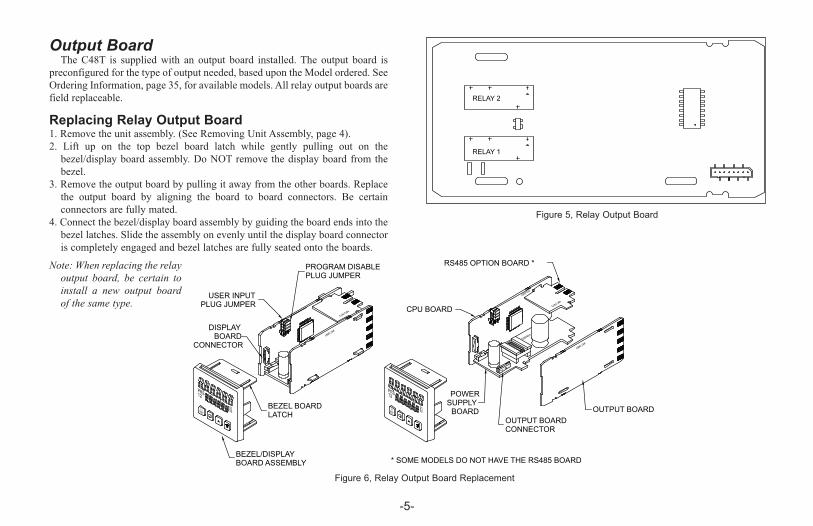
Output Board The C48T is supplied with an output board installed. The output board is
preconfigured for the type of output needed, based upon the Model ordered. SeeOrdering Information, page 35, for available models. All relay output boards arefield replaceable.
Replacing Relay Output Board 1. Remove the unit assembly. (See Removing Unit Assembly, page 4).2. Lift up on the top bezel board latch while gently pulling out on thebezel/display board assembly. Do NOT remove the display board from thebezel.
3. Remove the output board by pulling it away from the other boards. Replacethe output board by aligning the board to board connectors. Be certainconnectors are fully mated.
4. Connect the bezel/display board assembly by guiding the board ends into thebezel latches. Slide the assembly on evenly until the display board connectoris completely engaged and bezel latches are fully seated onto the boards.
Note: When replacing the relayoutput board, be certain toinstall a new output boardof the same type.
-5-
RS485 OPTION BOARD *
OUTPUT BOARDCONNECTOR
OUTPUT BOARD
POWERSUPPLY
BOARD
CPU BOARD
BEZEL/DISPLAYBOARD ASSEMBLY
BEZEL BOARDLATCH
DISPLAYBOARD
CONNECTOR
* SOME MODELS DO NOT HAVE THE RS485 BOARD
USER INPUTPLUG JUMPER
PROGRAM DISABLEPLUG JUMPER
MC1968
EB0783
0201
PRS12
F1RST
EB0924
MC1973
MC1968
MC1973
F1RST
PRS12
0102
RELAY 2
RELAY 1
Figure 6, Relay Output Board Replacement
Figure 5, Relay Output Board

EMC INSTALLATION GUIDELINESAlthough Red Lion Controls products are designed with a high degree of
immunity to Electromagnetic Interference (EMI), proper installation and wiringmethods must be followed to ensure compatibility in each application. The typeof the electrical noise, source or coupling method into a unit may be differentfor various installations. Cable length, routing, and shield termination are veryimportant and can mean the difference between a successful or troublesomeinstallation. Listed are some EMI guidelines for a successful installation in anindustrial environment.1. A unit should be mounted in a metal enclosure, which is properly connectedto protective earth.
2. Use shielded cables for all Signal and Control inputs. The shield connectionshould be made as short as possible. The connection point for the shielddepends somewhat upon the application. Listed below are the recommendedmethods of connecting the shield, in order of their effectiveness.a. Connect the shield to earth ground (protective earth) at one end where theunit is mounted.
b. Connect the shield to earth ground at both ends of the cable, usually whenthe noise source frequency is over 1 MHz.
3. Never run Signal or Control cables in the same conduit or raceway with ACpower lines, conductors, feeding motors, solenoids, SCR controls, andheaters, etc. The cables should be run through metal conduit that is properlygrounded. This is especially useful in applications where cable runs are longand portable two-way radios are used in close proximity or if the installationis near a commercial radio transmitter. Also, Signal or Control cables withinan enclosure should be routed as far away as possible from contactors,control relays, transformers, and other noisy components.
4. Long cable runs are more susceptible to EMI pickup than short cable runs.5. In extremely high EMI environments, the use of external EMI suppressiondevices such as Ferrite Suppression Cores for signal and control cables iseffective. The following EMI suppression devices (or equivalent) arerecommended:Fair-Rite part number 0443167251 (Red Lion Controls #FCOR0000)Line Filters for input power cables:Schaffner # FN2010-1/07 (Red Lion Controls #LFIL0000)
6. To protect relay contacts that control inductive loads and to minimize radiatedand conducted noise (EMI), some type of contact protection network is
normally installed across the load, the contacts or both. The most effectivelocation is across the load.a. Using a snubber, which is a resistor-capacitor (RC) network or metal oxidevaristor (MOV) across an AC inductive load is very effective at reducingEMI and increasing relay contact life.
b. If a DC inductive load (such as a DC relay coil) is controlled by a transistorswitch, care must be taken not to exceed the breakdown voltage of thetransistor when the load is switched. One of the most effective ways is toplace a diode across the inductive load. Most Red Lion products with solidstate outputs have internal zener diode protection. However external diodeprotection at the load is always a good design practice to limit EMI.Although the use of a snubber or varistor could be used.Red Lion part numbers: Snubber: SNUB0000
Varistor: ILS11500 or ILS230007. Care should be taken when connecting input and output devices to theinstrument. When a separate input and output common is provided, theyshould not be mixed. Therefore a sensor common should NOT be connectedto an output common. This would cause EMI on the sensitive input common,which could affect the instrument’s operation.Visit http://www.redlion.net/emi for more information on EMI guidelines,
Safety and CE issues as they relate to Red Lion products.
Wiring Connections All conductors should meet voltage and current ratings for each terminal.
Also cabling should conform to appropriate standards of good installation, localcodes and regulations. It is recommended that power supplied to the unit (ACor DC) be protected by a fuse or circuit breaker.After the unit has been mechanically mounted, it is ready to be wired. All
wiring connections are made to rear screw terminals. When wiring the unit, usethe numbers on the label and those embossed on the back of the case, to identifythe position number with the proper function (See page 35, for terminaldescriptions). Strip the wire, leaving approximately 1/4² (6 mm) bare wireexposed (stranded wires should be tinned with solder). Insert the wire under theclamping washer and tighten the screw until the wire is clamped tightly.Caution: Unused terminals are NOT to be used as tie points. Damage to the
timer may result if these terminals are used.
-6-

POWER WIRINGAC Versions (C48TXX0X)AC Power Wiring
Primary AC power is connected to terminals 11 and 12, labeled AC. To
reduce the chance of noise spikes entering the AC line and affecting the timer,
an AC feed separate from that of the load should be used to power the timer. Be
certain that the AC power to the timer is relatively “clean” and within the
specified range. Connecting power from heavily loaded circuits or circuits that
also power loads that cycle on and off, (contacts, relays, motors, etc.) should be
avoided.
DC Power Wiring (Non PNP Output models)The DC power is connected to terminals 9 & 10, marked COMM. and DC
OUT/IN. The DC power source must be capable of supplying the unit’s rated
current (150 mA max.) and be within the specified 11 to 14 VDC range. The
C48T has non-volatile memory, that stores information on power down, thereby
eliminating the need for battery back-up.
Note: AC versions with PNP outputs cannot be powered from DC.
Caution: Observe proper polarity when connecting DC voltages.
Damage to the unit will occur if polarity is reversed.
DC Versions (C48TXX1X)DC power (18 to 36 VDC) or low voltage AC power (24 VAC) is connected
to terminals 11 and 12, labeled DC+ (AC) and DC- (AC) respectively.
Output PowerFor DC/ Low Voltage units that do not have PNP current sourcing outputs,
Terminal 10, DC OUT (VSRC IN), provides a DC output for sensor power (+12
VDC +/-15%). The maximum sensor current is 100 mA.
For units with PNP current sourcing outputs, this terminal serves a dual
purpose depending on the application’s PNP output voltage level and current
requirements.
1. The terminal may be used as a +12 VDC output for sensor power. In this
case, the PNP output voltage level will be +12 VDC (±15%). A maximum
of 100 mA is available for the combination of sensor current and PNP
output sourcing current.
2. If a higher PNP output voltage level or additional output sourcing current
is desired, an external DC supply may be connected between the “DC
OUT (VSRC IN)” and “COMM.” terminals. This supply will determine the
PNP output voltage level, and must be in the range of +13 to +30 VDC.
An external DC supply can also provide the additional output sourcing
current required in applications where two or more PNP outputs are
“ON” simultaneously. However, the maximum current rating of 100
mA per individual output must not be exceeded, regardless of external
supply capacity.
Serial Communications WiringIt is recommended that shielded (screened) cable be used for serial
communications. This unit meets the EMC specifications using Alpha #2404
cable or equivalent. There are higher grades of shielded cable, such as, four
conductor twisted pair, that offer an even higher degree of noise immunity.
Refer to RS-485 Serial Communications, page 24, for wiring and operational
procedures.
Run/Stop InputThe RUN/STOP input can be configured as a current sinking (active low) or
current sourcing (active high) input using the User Input plug jumper. The timer
will RUN when RUN/STOP (terminal #7) is connected to the active logic level.
See chart on Page 8, for active and inactive voltage levels for each User Input
plug jumper setting.
In some operating modes, the timer will automatically STOP timing when the
main output is triggered. (See Timer Operating Modes in the programming
section, Page 13.) In these modes, the RUN/STOP input can be used to restart
the timer by momentarily taking the input to the STOP state (inactive logic
level) and then back to the RUN state (active logic level). Cycling the
RUN/STOP terminal, however, will not reset or affect the output(s).
-7-
C48t-im.QXD 3/5/04 3:28 PM Page 7

-8-
User InputsThe three external user inputs are programmable inputs that can be
configured as current sinking (active low) or current sourcing (active high)inputs via a single plug jumper. Programmable external user inputs are digitalinputs. The use of shielded cable is recommended. Follow the EMC InstallationGuidelines for shield connection. See User Inputs, page 19, for a description ofall available user input functions. The active logic state of ALL user inputs isdictated by the position of the User Input plug jumper. The plug jumper islocated on the CPU board (See Figure 9, User Input and Program DisableJumper Locations).
OUTPUT WIRINGRelay ConnectionsTo prolong contact life and suppress electrical noise interference due to the
switching of inductive loads, it is good installation practice to install a snubberacross the contactor. Follow the manufacturer’s instructions for installation.Note: Snubber leakage current can cause some electro-mechanical devices to be
held ON.
Program Disable Plug JumperThe program disable plug jumper is used to enable and disable front panel
programming of the C48T. See Front Panel Accessible Functions With ProgramDisable, page 11, for a description of available functions. The plug jumper islocated on the CPU board (See Figure 9, User Input and Program DisableJumper Locations).
USER INPUT AND PROGRAMDISABLE PLUG JUMPERS
Figure 9, User Input and Program Disable Jumper Locations
User Input Jumper
Current Sinking (Factory Setting)(Active Low)
Current Sourcing(Active High)
Figure 7, User Input Jumper Settings
Program Disable Jumper
Program Disable OFF (Factory Setting)(Programming Enabled)
Program Disable ON(Programming Disabled)
Figure 8, Program Disable Jumper Settings
User Input StateInput Voltage Level for Jumper Position
Source Sink *
Active Vin > 3.5 VDC Vin < 1.5VDCInactive Vin < 1.5 VDC Vin > 3.5VDC
* Factory Setting

FRONT PANEL DESCRIPTIONThe front panel bezel material is flame and scratch resistant, textured plastic
with clear viewing window that meets NEMA 4X/IP65 requirements, whenproperly installed. Continuous exposure to direct sunlight might accelerate theaging process of the plastic material used in the bezel. The bezel should becleaned only with a soft cloth and neutral soap product. Do NOT use solvents.The display is a dual line, 6 digit LCD. On units with backlighting, the upper
Main Display is red and the lower Secondary Display is green.There are up to five annunciators available in the lower display that
illuminate to inform the operator of the timer and output status. See Figure 10,Front Panel, for a description of the annunciators.Four front panel keys are used to access different modes and parameters. The
following is a description of each key.Do not use tools of any kind (screwdrivers, pens, pencils, etc.) to operate the
keypad of this unit.
Keypad FunctionsD - This key is a user programmable key. When the key is pressed, the unitperforms the appropriate function as programmed. The RST printing onthis key is used as a quick reference for the operator if the function key isselected for a reset function.
A - This key is used to access programming, enter changes to data values,and scroll through the available parameters in any mode.
B - This key selects the next available mode option during programming.When programming a numerical value in digit entry mode, this key is usedto increment the selected digit position. In auto scrolling entry mode, itincrements the value. When in the operating mode, this key is pressed toallow changing of the data value viewed in the secondary display.
C - When programming a numerical value in digit entry mode, this keyaccesses the value and selects the digit to the right. In auto scrolling entrymode, it decrements the value. When in the operating mode, this key ispressed to allow changing of the data value viewed in the secondarydisplay.
-9-
MAIN DISPLAY
SECONDARY DISPLAYOUTPUT ANNUNCIATORS
VALUE ANNUNCIATORS
Displays timer value.Also displays mnemonic of selected parameter in Programming Menu.
Displays the preset or output time values.Also displays mnemonic or numeric value when modifying a parameter.
Indicate which value isbeing viewed or modified.
RSTF1
21PRS 0
012
Figure 10 , Front Panel

BASIC OPERATION
Normal Operating ModeIn the normal operating mode, the timer value is shown on the main
display. By successively pressing the � key, the accessible presets or
output time values can be viewed in the secondary display.
Each of these values can be independently programmed to be viewable
only, viewable and changeable, or locked (not viewable) in the normal
operating mode. If all values are locked, the secondary display will be
blank. Only from the normal operating mode can access be gained to the
Programming Menu or Protected Value Menu.
Modifying A Secondary DisplayParameter From the Front Panel
Secondary display parameters can be modified from the normal
operating mode if the Operator Access privileges allow it.
To modify a parameter, it must be viewed in the secondary display.
When the parameter to be modified is viewed, press the � or � key.
Leading zeros appear and the least significant digit blinks. The value can
now be modified as described in Programming Numeric Data Values, page
12.
Protected Value Menu The Protected Value Menu allows access to selected presets and output
time values without having them viewable or changeable from the main
display. To enter the protected menu, the � key is pressed and held, and a
code value is entered. The Protected Value Menu and the Programming
Menu are not available at the same time. See Front Panel Accessible
Functions With Program Disable, page 11, for available options.
Access value parameters that are programmed for “P” or “n” are
accessible in the Protected Value Menu. Parameters selected as “n” (no) are
viewable from the main display, but can only be changed in the protected
menu. Parameters selected as “P” (protected) are not viewable from the
main display, but can be viewed and changed in the protected menu.
-10-
Figure 11, Protected Value Menu
C48t-im.QXD 3/5/04 3:28 PM Page 10

There are several ways to limit the programming of parameters from the front
panel keypad. The Accessible Value parameter is used with the Program Disable
plug jumper and an external programmable User Input selected for Pro.dis to
limit programming. To enter the programming mode, a code number may need
to be entered, depending on the Program Disable Setting. Front Panel Function
Key F1 cannot be selected for program disable. The following table describes
the possible program disabling functions.
-11-
Front Panel Accessible Functions With Program Disable
PGM.DIS.
JUMPERUSER INPUT TERMINAL
PROGRAM CODE
NUMBER
PROTECTED VALUE
MENU
OPERATOR ACCESS AT
MAIN DISPLAY
PROGRAM
DISABLE LEVEL
PROGRAMMING
ENABLED
OFF (EN)INACTIVE or NotProgrammed for Pro.dis
ALL NoAll displayed valueschangeable
NoneYes
OFF (EN) ACTIVE 0 NoPer Access Privilegesprogrammed
Level 1No
OFF (EN) ACTIVE 1 to 99Yes
W/codePer Access Privilegesprogrammed
Level 1No
OFF (EN) ACTIVE 100 to 199 NoPer Access Privilegesprogrammed
Level 1Yes
W/code
ON (DIS)INACTIVE or NotProgrammed for Pro.dis
0 NoPer Access Privilegesprogrammed
Level 1No
ON (DIS)INACTIVE or NotProgrammed for Pro.dis
1 to 99Yes
W/codePer Access Privilegesprogrammed
Level 1No
ON (DIS)INACTIVE or NotProgrammed for Pro.dis
100 to 199 NoPer Access Privilegesprogrammed
Level 1Yes
W/code
ON (DIS) ACTIVE ALL No Viewable only Level 2No
C48t-im.QXD 3/5/04 3:28 PM Page 11

Programming of the C48T is done through the front panel keypad. English
language prompts, flashing parameter values, and the front panel keypad aid the
operator during programming.
Although the unit has been programmed at the factory, the parameters
generally have to be changed to suit the desired application. In order to access
the Programming Menu, the Program Disable jumper and/or any User Input
programmed for Pro.dIS may need to be turned off or deactivated. When
shipped from the factory, all programming is enabled. See Front Panel
Accessible Functions With Program Disable, page 11, for program disabling
options. With programming enabled, to enter the programming menu, the �key is pressed and held for two seconds. Once in the programming menu, the
� key is used to sequence through the list of programming parameters. To loop
backwards one item in the Programming Menu, press and hold the � key, then
quickly press and hold the � key while releasing the � key. Repeatedly
pressing the � key with the � key held will continue the backwards
sequencing.
Programming Option ValuesThe operator can scroll through the available options for a selected parameter
by pressing the � or � key to enter parameter change mode, and then pressing
the � key repeatedly until the desired option is viewed. The option is entered
by pressing the � key, which returns the operator to the Programming Menu.
Programming Numeric Data ValuesThe Presets and output time values may be accessible when the unit is in the
normal operating mode (not programming mode), providing that the Program
Disable input is not activated. Pressing the � key will sequence the secondary
display through the available presets and output time values.
To change a numeric data value, it must be visible on the secondary display.
Pressing the � or � key will allow changing of the value. The two methods
for changing numeric data values are “digit entry” and “auto scrolling”.
Digit EntryIf the preset entry method has been set to “digit entry”, the least significant
digit will blink. Pressing the � key multiple times will select other digits.
Pressing the � key will increment the selected digit. The data value will be
entered when the � key is pushed, or the old value will be retained if no key
activity is detected for 10 seconds.
Short-Cut - Decrementing Value
To decrement a digit value, press and hold the � key and then press the �key. This will decrement the selected digit to zero if held.
Auto ScrollingIf the data entry method is set to “auto scrolling”, the data value can be
progressively changed by pressing and holding the � or � keys. If one of the
keys is pushed and held, the value will scroll automatically. After 5 counts, the
unit enters fast scroll mode. If a key remains pushed, a digit shift occurs every
one hundred counts until the maximum value or zero is reached. When the digit
shift occurs, the previously scrolling digit goes to zero. When scrolling at the
higher order digit locations, you can switch directions by quickly pressing the
other key (� or � ) within a second following the release of previous direction
key.
Short-Cut - Quick Digit Shift
To quickly select higher order digits while incrementing or decrementing
numeric values (with � or � held), press and hold the � key. This sequences
the selected digit from the least to the most significant digit. As each digit is
passed, it changes to zero. When the desired digit is reached, release the � key
to increment or decrement from the new digit location.
Saving ProgramAll parameter values changed in programming mode are saved when exiting.
To exit programming mode, press and hold the � key for two seconds. The
display will momentarily display Pro9 SAVE while the parameter values are
saved in non-volatile memory. The unit then returns to the indication display
that was last viewed.
-12-
PROGRAMMING GENERAL DESCRIPTION
C48t-im.QXD 3/5/04 3:28 PM Page 12
The operating modes of the C48T are programmed using the front panel
keypad. (See page 12, for details on using the keypad to program the unit)
Accessibility to the Programming Menu depends on the Program Disable
Function setting (See page 11, for available program disable settings).
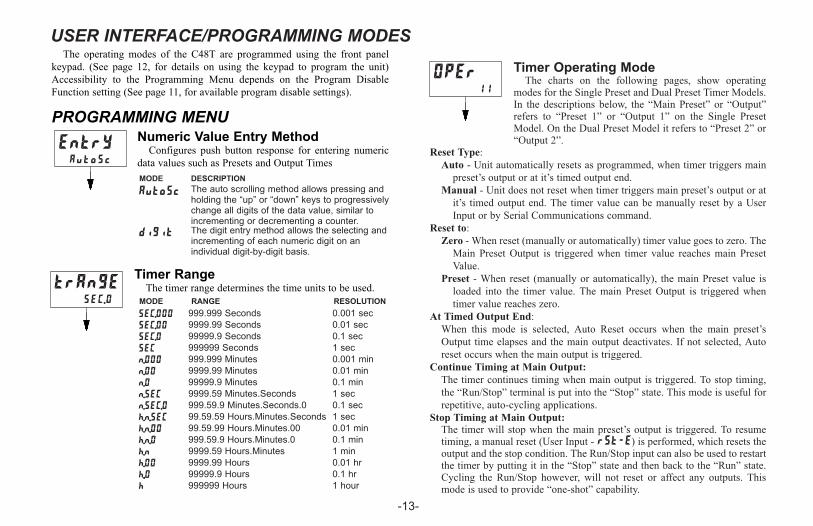
PROGRAMMING MENUNumeric Value Entry Method
Configures push button response for entering numeric
data values such as Presets and Output Times
Timer RangeThe timer range determines the time units to be used.trAnGE
SEC.0
-13-
Timer Operating ModeThe charts on the following pages, show operating
modes for the Single Preset and Dual Preset Timer Models.In the descriptions below, the “Main Preset” or “Output”refers to “Preset 1” or “Output 1” on the Single PresetModel. On the Dual Preset Model it refers to “Preset 2” or“Output 2”.
Reset Type:
Auto - Unit automatically resets as programmed, when timer triggers main
preset’s output or at it’s timed output end.
Manual - Unit does not reset when timer triggers main preset’s output or at
it’s timed output end. The timer value can be manually reset by a User
Input or by Serial Communications command.
Reset to:
Zero - When reset (manually or automatically) timer value goes to zero. The
Main Preset Output is triggered when timer value reaches main Preset
Value.
Preset - When reset (manually or automatically), the main Preset value is
loaded into the timer value. The main Preset Output is triggered when
timer value reaches zero.
At Timed Output End:
When this mode is selected, Auto Reset occurs when the main preset’s
Output time elapses and the main output deactivates. If not selected, Auto
reset occurs when the main output is triggered.
Continue Timing at Main Output:
The timer continues timing when main output is triggered. To stop timing,
the “Run/Stop” terminal is put into the “Stop” state. This mode is useful for
repetitive, auto-cycling applications.
Stop Timing at Main Output:
The timer will stop when the main preset’s output is triggered. To resumetiming, a manual reset (User Input - rSt-E) is performed, which resets theoutput and the stop condition. The Run/Stop input can also be used to restartthe timer by putting it in the “Stop” state and then back to the “Run” state.Cycling the Run/Stop however, will not reset or affect any outputs. Thismode is used to provide “one-shot” capability.
OPEr11
USER INTERFACE/PROGRAMMING MODES
MODE DESCRIPTION
diGit The digit entry method allows the selecting andincrementing of each numeric digit on anindividual digit-by-digit basis.
AutoSc
EntrYAutoSc
1 hour
0.01 hr
0.1 hr
1 min
0.1 min
999999 Hours
9999.99 Hours
99999.9 Hours
9999.59 Hours.Minutes
999.59.9 Hours.Minutes.0
h
h.00
h..0
h.n
h.n.0
0.01 min99.59.99 Hours.Minutes.00h.n.00
1 sec99.59.59 Hours.Minutes.Secondsh.n.SEC
0.1 sec999.59.9 Minutes.Seconds.0n.SEC.0
1 sec9999.59 Minutes.Secondsn.SEC
0.1 min99999.9 Minutesn.0
0.01 min9999.99 Minutesn.00
0.001 min999.999 Minutesn.000
1 sec999999 SecondsSEC
0.1 sec99999.9 SecondsSEC.0
0.01 sec9999.99 SecondsSEC.00
0.001 sec999.999 SecondsSEC.000
RESOLUTIONRANGEMODE
The auto scrolling method allows pressing andholding the “up” or “down” keys to progressivelychange all digits of the data value, similar toincrementing or decrementing a counter.
C48t-im.QXD 3/5/04 3:28 PM Page 13

SINGLE PRESET OPERATING MODES
Use either of the two charts on this page for more information on specific
operating modes.
-14-
Stop Timing at 01, Auto Reset to Preset 1 at 01 End, Timed Output
Stop Timing at 01, Manual Reset to Zero, Latched Output
Stop Timing at 01, Auto Reset to Zero at 01 End, Timed Output
Stop Timing at 01, Auto Reset to Preset 1, Timed Output
Continue Timing at 01, Auto Reset to Zero at 01 End, Timed Output
Stop Timing at 01, Auto Reset to Preset 1, Latched Output
Continue Timing at 01, Auto Reset to Preset 1, Timed Output
Stop Timing at 01, Auto Reset to Zero, Timed Output
Continue Timing at 01, Auto Reset to Zero, Timed Output
Stop Timing at 01, Auto Reset to Zero, Latched Output
Continue Timing at 01, Manual Reset to Preset 1, Timed Output
Stop Timing at 01, Manual Reset to Preset 1, Timed Output
Continue Timing at 01, Manual Reset to Preset 1, Latched Output
Stop Timing at 01, Manual Reset to Preset 1, Latched Output
Continue Timing at 01, Manual Reset to Zero, Timed Output
Stop Timing at 01, Manual Reset to Zero, Timed Output
Continue Timing at 01, Manual Reset to Zero, Latched Output
-
-
-
-
-
-
-
-
-
-
-
-
-
-
-
-
-
-
18
9
17
8
16
7
15
6
14
5
13
4
12
3
11
2
10
1
SINGLE PRESET OPERATING MODES
RESET TYPE RESET OUTPUT 1
Sin
gle
Pre
set
Mo
des
Man
ual
Au
to
To
Zero
To
Pre
set 1
at T
imed
Ou
tpu
t En
d
Latc
hed
Tim
ed
1 � �� �
2 � �� �
3 � �� �
4 � �� �
5 � �� �
6 � �� �
7 � � �� �
8 � � �� �
9 � �� �
10 � �� �
11 � �� �
12 � �� �
13 � �� �
14 � �� �
15 � �� �
16 � �� �
17 � � �� �
18 � � �� �
MODE#
Output 1: (Main Output for Single Preset Model)
Latched - When Output 1 activates it stays activated or latched until it is
manually reset.Timed - When Output 1 is activated it stays activated for the time specified
by the Output 1 Time Value. Output 1 deactivates after the Output 1 timeelapses.
O1 Off at O2: (Dual Preset only)
Output 1 activates at Preset 1. It deactivates when Output 2 is activated.
(Does not apply to activation from Serial command.)Output 2: (Dual Preset Model only; Main Output)
Operates similarly to Output 1 Latched and Timed modes.
Continue Timing at 01, Auto Reset to Preset 1 at 01 End, Timed Output
CO
NT
INU
E T
imin
g
at 0
1
ST
OP
Tim
ing
at 0
1
C48t-im.QXD 3/5/04 3:29 PM Page 14

DUAL PRESET OPERATING MODES
Use either of the two charts on the next two pages for more information on
specific operating modes.
-15-
Continue Timing at 02, Auto Reset to Zero at 02 End, 01 and 02 Timed
Continue Timing at 02, Auto Reset to Preset 2, 01 off at 02, 02 Timed
Continue Timing at 02, Auto Reset to Preset 2, 01 and 02 Timed
Continue Timing at 02, Auto Reset to Zero, 01 off at 02, 02 Timed
Continue Timing at 02, Auto Reset to Zero, 01 and 02 Timed
Continue Timing at 02, Manual Reset to Preset 2, 01 and 02 Timed
Continue Timing at 02, Manual Reset to Preset 2, Latched Outputs
Continue Timing at 02, Manual Reset to Zero, 01 off at 02, 02 Timed
Continue Timing at 02, Manual Reset to Zero, 01 off at 02, 02 Latched
Continue Timing at 02, Manual Reset to Zero, 01 and 02 Timed
Continue Timing at 02, Manual Reset to Zero, 01 Timed, 02 Latched
Continue Timing at 02, Manual Reset to Zero, Latched Outputs-
-
-
-
-
-
-
-
-
-
-
-
-
-
-
-
-
-18
17
16
15
14
13
12
11
10
9
8
7
6
5
4
3
2
DUAL PRESET OPERATING MODES
1
OUTPUT 1
�
�
�
�
�
�
�
�
01 o
ff at 0
2
�
�
�
�
�
�
�
�
�
�
�
�
�
�
�
�
�
� ���18
�� ���17
� ���16
�� ���15
� ��14
�� ��13
� ��12
�� ��11
� ��10
� ��9
�� ��8
�� ��7
�� ��6
� ��5
� ��4
�� ��3
�� ��2
�� ��1
Tim
ed
Latc
hed
CO
NT
INU
E T
imin
g
at 0
2
at T
imed
Ou
tpu
t 2 E
nd
To
Pre
set 2
To
Zero
Au
to
Man
ual
Du
al P
reset
Mo
des
�
RESET
Tim
ed
Latc
hed
RESET TYPE OUTPUT 2MODE#
Continue Timing at 02, Manual Reset to Preset 2, 01 Timed, 02 Latched
Continue Timing at 02, Manual Reset to Preset 2, 01 off at 02, 02 Latched
Continue Timing at 02, Manual Reset to Preset 2, 01 off at 02, 02 Timed
Continue Timing at 02, Auto Reset to Zero at 02 End, 01 off at 02, 02 Timed
Continue Timing at 02, Auto Reset to Preset 2 at 02 End, 01 and 02 Timed
Continue Timing at 02, Auto Reset to Preset 2 at 02 End, 01 off at 02, 02Timed
C48t-im.QXD 3/5/04 3:29 PM Page 15

-16-
Stop Timing at 02, Auto Reset to Preset 2 at 02 End, 01 and 02 Timed
-
-
-42
41
40
Stop Timing at 02, Auto Reset to Preset 2, 01 off at 02, 02 Timed
Stop Timing at 02, Auto Reset to Preset 2, 01 and 02 Timed
Stop Timing at 02, Auto Reset to Preset 2, 01 Timed, 02 Latched
Stop Timing at 02, Auto Reset to Preset 2, Latched Outputs
Stop Timing at 02, Auto Reset to Zero, 01 off at 02, 02 Timed
Stop Timing at 02, Auto Reset to Zero, 01 off at 02, 02 Latched
Stop Timing at 02, Auto Reset to Zero, 01 and 02 Timed
Stop Timing at 02, Auto Reset to Zero, 01 Timed, 02 Latched
Stop Timing at 02, Auto Reset to Zero, Latched Outputs
Stop Timing at 02, Manual Reset to Preset 2, 01 off at 02, 02 Timed
Stop Timing at 02, Manual Reset to Preset 2, 01 off at 02, 02 Latched
Stop Timing at 02, Manual Reset to Preset 2, 01 and 02 Timed
Stop Timing at 02, Manual Reset to Preset 2, 01 Timed, 02 Latched
Stop Timing at 02, Manual Reset to Preset 2, Latched Outputs
Stop Timing at 02, Manual Reset to Zero, 01 off at 02, 02 Timed
Stop Timing at 02, Manual Reset to Zero, Latched Outputs
Stop Timing at 02, Manual Reset to Zero, 01 Timed, 02 Latched
Stop Timing at 02, Manual Reset to Zero, 01 and 02 Timed
Stop Timing at 02, Manual Reset to Zero, 01 off at 02, 02 Latched
-
-
-
-
-
-
-
-
-
-
-
-
-
-
-
-
-
-
-
-
-39
38
37
36
35
34
33
32
31
30
29
28
27
26
25
24
23
19
20
21
22
DUAL PRESET OPERATING MODES
Stop Timing at 02, Auto Reset to Preset 2, 01 off at 02, 02 Latched
Stop Timing at 02, Auto Reset to Zero at 02 End, 01 and 02 Timed
Stop Timing at 02, Auto Reset to Preset 2 at 02 End, 01 off at 02, 02Timed �
�
�
�
�
�
�
�
�
�
�
�
42
39
�
�
�
�
�
�
��
�
�
�
41
38
��
� �
�
�
�
�
��
�
40
37
��� ��36
� �� ��35
��� ��34
��� ��33
� �� ��32
��� ��31
� �� ��30
��� ��29
��� ��28
� �� ��27
��� ��26
� �� ��25
��� ��24
��� ��23
�
�
�
�
�
�
�
��
�
�
�
�
�
�
�
�
�
�
�
19
20
21
22
Tim
ed
01 o
ff at 0
2
Tim
ed
Latc
hed
Latc
hed
ST
OP
Tim
ing
at 0
2
at T
imed
Ou
tpu
t 2 E
nd
To
Pre
set 2
To
Zero
Au
to
Man
ual
Du
al P
reset
Mo
des
OUTPUT 2OUTPUT 1RESETRESET TYPEMODE#
Stop Timing at 02, Auto Reset to Zero at 02 End, 01 off at 02, 02 Timed
C48t-im.QXD 3/5/04 3:29 PM Page 16

Timer Reset at Power-upThis parameter determines whether or not the timer is
reset when power is applied to the unit.
Access Preset ValuesThis parameter configures the type of access given to
each Preset Value when in normal operating mode and at
Program Disable Level 1. The accessibility of each Preset
can be individually configured. For more information on
Program Disable, see Front Panel Accessible Functions
With Program Disable, page 11.
Programming Keys:
� - Selects Preset Value being configured as indicated by
the number on the left side of the bottom display line.
� - Changes mode selection for selected Preset.
-17-
Preset 1 ValueThe Preset 1 value is used to control the activation of
Output 1.
Preset 2 Value (Dual Preset Model only)
The Preset 2 value is used to control the activation of
Output 2.
Preset 1 Track Preset 2 (Dual Preset Model
only)This parameter configures whether or not the Preset 1
value tracks or follows the Preset 2 value.
Ac PrSPRS
-y
rSt.P.uPno
Ac PrSPRS
-y-y
PrESEtPRS2 2.0
PltrAcPRS2 no
PrESEtPRS1 1.0
MODE DESCRIPTION
-L Locked; Preset is not viewable at main display orin Protected Value Menu. The Preset can only beviewed or changed in the Programming Menu.
-y
-n
-P Protected Value; Preset value is viewable andchangeable in Protected Value Menu only. It is notviewable at Main Display.
Single PresetModel
Dual PresetModel
Dual PresetModel
Dual PresetModel
MODE DESCRIPTION
no Preset 1 does not track Preset 2
YEs Preset 1 tracks Preset 2 value. When Preset 2value is changed, the Preset 1 value will changeto maintain the same offset. Changing Preset 1will modify the offset.
-OR-
Yes; Preset value is viewable and changeable atmain display when at 1st level program disable.Value is not shown in Protected Value Menu.
No; Preset value is viewable only and notchangeable from main display when Programmingis Disabled. Value is viewable and changeable inProtected Value Menu.
Timer is reset at power-up.YEs
no
DESCRIPTIONMODE
Timer is not reset at power-up. The timer valuesaved at the previous power-down is restored tothe display.
C48t-im.QXD 3/5/04 3:29 PM Page 17
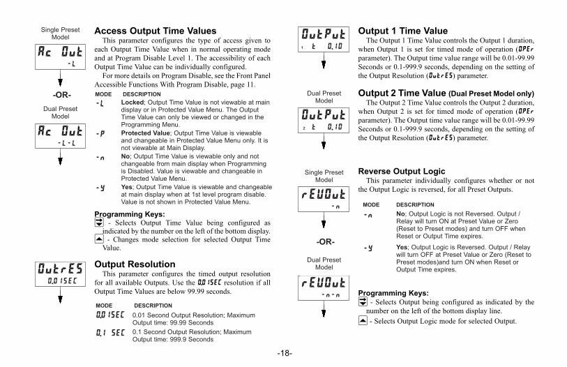
Access Output Time ValuesThis parameter configures the type of access given to
each Output Time Value when in normal operating mode
and at Program Disable Level 1. The accessibility of each
Output Time Value can be individually configured.
For more details on Program Disable, see the Front Panel
Accessible Functions With Program Disable, page 11.
Programming Keys:� - Selects Output Time Value being configured as
indicated by the number on the left of the bottom display.� - Changes mode selection for selected Output Time
Value.
Output ResolutionThis parameter configures the timed output resolution
for all available Outputs. Use the 0.01SEC resolution if all
Output Time Values are below 99.99 seconds.
-18-
Output 1 Time ValueThe Output 1 Time Value controls the Output 1 duration,
when Output 1 is set for timed mode of operation (OPEr
parameter). The Output time value range will be 0.01-99.99
Seconds or 0.1-999.9 seconds, depending on the setting of
the Output Resolution (OutrES) parameter.
Output 2 Time Value (Dual Preset Model only)
The Output 2 Time Value controls the Output 2 duration,
when Output 2 is set for timed mode of operation (OPEr
parameter). The Output time value range will be 0.01-99.99
Seconds or 0.1-999.9 seconds, depending on the setting of
the Output Resolution (OutrES) parameter.
Reverse Output LogicThis parameter individually configures whether or not
the Output Logic is reversed, for all Preset Outputs.
Programming Keys:
� - Selects Output being configured as indicated by the
number on the left of the bottom display line.
� - Selects Output Logic mode for selected Output.
Ac Out-L
Ac Out-L-L
OutrES0.01SEC
rEVOut-n
rEVOut-n-n
OutPut1 t 0.10
OutPut2 t 0.10
MODE DESCRIPTION
-L
-y
-n
-P Protected Value; Output Time Value is viewableand changeable in Protected Value Menu only. It isnot viewable at Main Display.
MODE DESCRIPTION
0.01SEC 0.01 Second Output Resolution; MaximumOutput time: 99.99 Seconds
0.1 SEC 0.1 Second Output Resolution; MaximumOutput time: 999.9 Seconds
Dual PresetModel
MODE DESCRIPTION
-n
-Y
Locked; Output Time Value is not viewable at maindisplay or in Protected Value Menu. The OutputTime Value can only be viewed or changed in theProgramming Menu.
Yes; Output Time Value is viewable and changeableat main display when at 1st level program disable.Value is not shown in Protected Value Menu.
No; Output Logic is not Reversed. Output /Relay will turn ON at Preset Value or Zero(Reset to Preset modes) and turn OFF whenReset or Output Time expires.
Yes; Output Logic is Reversed. Output / Relaywill turn OFF at Preset Value or Zero (Reset toPreset modes)and turn ON when Reset orOutput Time expires.
Single PresetModel
Single PresetModel
Dual PresetModel
-OR-
Dual PresetModel
-OR-
No; Output Time Value is viewable only and notchangeable from main display when Programmingis Disabled. Value is viewable and changeable inProtected Value Menu.
C48t-im.QXD 3/5/04 3:29 PM Page 18

Reverse Annunciator LogicThis parameter controls the logic state of the Output
Display Annunciators (‘01’ and ‘02’).
Programming Keys:
� - Selects Output Annunciator being configured as
indicated by the number on the left side of the bottom
display line.
� - Selects Output Annunciator Logic for selected Output.
Output Power-Up StateThis parameter controls the Power-Up State of the
Outputs.
Programming Keys:
� - Selects Output being configured as indicated by the
number on the left side of the bottom display line.
� - Selects Output Power-up state for selected Output.
-19-
User InputsThree external User Inputs plus the front panel function key are available on
the C48 Timer. The parameter list below shows all available user input
functions. The Input Pull-Up / Pull-down resistor and Active logic level for all
of the User Inputs is configured with the Snk/Src jumper (See page 8).
rEVAnu-n
rEVAnu-n-n
OutP.uP-F
OutP.uP-F-F
MODE DESCRIPTION
-n
-Y Yes; Output Annunciator Logic is Reversed.Output Annunciator will be ON when the Outputis OFF.
No; Output Annunciator Logic is not Reversed.Output Annunciator will be ON when the Outputis ON.
MODE DESCRIPTION
-f Off; The output will be off at power-up.
-O On; The output will turn on at power-up.
-P Previous State; For latched output modes only.The output will power-up in the state it was in atpower-down. For non-latched modes, theoutput will power-up in the off state.
DESCRIPTIONMODE
StorE
St.rS-L
dn-L
Pro.diS
ChgdSP
rSt. -E
rSt. -L
St.rS-E
Store; When the user input is activated, the main display will ‘freeze’and remain frozen until user input is released. See Note 1.
Store&Reset (Level Active Reset); When the user input is activated,the timer display will freeze and the internal Timer value will reset.The timer value will be frozen and internally held reset as long as theuser input is held active. See Notes 1 and 2.
Reset (Level Active); When the user input is activated, the timer valueand outputs will be reset and held reset until the user input isreleased. See Note 2
Program Disable [Level Active] (not available for F1 Key); See page10 for details of Program Disable options.
Change Display (Edge Triggered); When the user input is activated,the secondary display will sequence to the next available value.
Reset (Edge Triggered); When the user input is activated, the timervalue and outputs will be momentarily reset and then continue to timeand activate while the input is held active. See Note 2
Store&Reset (Edge Triggered Reset); When the user input isactivated, the display will freeze and be held until the user input isreleased. The internal Timer value resets momentarily and thencontinues to time while the input is held active. If the timer hadpreviously stopped as a result of the timer operating mode (See TimerOperating Mode, page 13), it will restart immediately following theedge triggered reset. See Notes 1 and 2.
Down (Level Active); (User Input 1 only) When User Input 1 is active,the unit will time down. When User Input 1 is inactive, the unit willtime up. This mode is normally not necessary, unless the applicationrequires both up and down timing.
Single PresetModel
Dual PresetModel
-OR-
Single PresetModel
Dual PresetModel
-OR-
C48t-im.QXD 3/5/04 3:29 PM Page 19

User Input 1User Input 1 can be programmed for any of the
parameters listed previously.
User Input 2User Input 2 can be programmed for any of the
parameters listed previously, except for down timing.
User Input 3User Input 3 can be programmed for any of the
parameters listed previously, except for down timing.
User F1 KeyUser F1 is the front panel function key. This user input
can be programmed for any of the parameters listed
previously, except for the Program Disable and down
timing function.
-20-
Programming/Protected ParameterMenu Code Value (0-199)
The Programming Code value can be used to provide
Data Value or Programming Menu security. Depending on
the Code range selected and the Program Disable Level, it
may be necessary to enter the code value before the unit
allows access to Programming Menus or Protected Values.
See Front Panel Accessible Functions With Program
Disable, page 11, for more information.
Scroll DisplayThis parameter configures whether or not the secondary
display will scroll or sequence automatically to the next
available value.
USrIn3rSt. -L
USr F1rSt. -L
CodE0
USrIn2rSt. -L
CODE VALUE DESCRIPTION
0 Programming is Disabled and Code entrydisplay is not available when Program isDisabled.
1-99 Protected Parameter Menu appears whenCode is entered and Program is Disabled.
100-199 Programming Menu appears when code isentered and Program is Disabled.
USrIn1rSt. -L
ScroLLno
MODE DESCRIPTION
no Disables or turns off display scrolling
YES Enables display scrolling (2.5 Sec display time)
Reset Outputs (Edge Triggered); When the user input is activated,all active outputs will reset to their inactive states. This is amomentary reset.
Print Request [Level Active] (RS485 Option only); When the userinput is activated, the timer and preset values, as configured in thePrint Options (PrnOPt) parameter, will be continually transmitted onthe RS485 terminals. See RS485 Serial Communications, page 24.
rStOut
DESCRIPTIONMODE
Note 1: Only one user input may be programmed for a StorE or StrS(Store&Reset) function.
Note 2: If the timer had previously stopped as a result of the timer Operatingmode (See Timer Operating Modes, page 13), it will restart following userinput release (level active reset modes) or immediately (edge triggered resetmodes).
C48t-im.QXD 3/5/04 3:29 PM Page 20

PrnOPt3
Timer
Value
Preset
Values
01 √
02 √
03 √ √
Serial Abbreviate MnemonicsWhen transmitting data, the unit can be programmed to
suppress the address number, mnemonics, and some spaces
by selecting YES for this parameter. A selection of YES
results in a faster transmission and may be useful when
interfacing with a computer. However, when interfacing
with a printer, sending mnemonics is usually desirable.
Print OptionsThe Print Options parameter determines which values
are printed in response to a Print Request command or user
input print request.
Serial Baud Rate and Parity SettingsThis parameter configures the Baud Rate and Parity
Settings for RS485 Serial Communications.
Serial Unit Address (00-99)This parameter configures the Serial Unit Address. This
address is used to uniquely identify each unit when multiple
units are connected on an RS485 bus.
-21-
SErSEt96n
SErAdr0
SErAbrno
DESCRIPTION
12n 1200 Baud; No Parity (8 data bits)
12o 1200 Baud; Odd Parity (7 data bits)
12E 1200 Baud; Even Parity (7 data bits)
24n 2400 Baud; No Parity (8 data bits)
24o 2400 Baud; Odd Parity (7 data bits)
24E 2400 Baud; Even Parity (7 data bits)
48n 4800 Baud; No Parity (8 data bits)
48o 4800 Baud; Odd Parity (7 data bits)
48E 4800 Baud; Even Parity (7 data bits)
96n 9600 Baud; No Parity (8 data bits)
96o 9600 Baud; Odd Parity (7 data bits)
96E 9600 Baud; Even Parity (7 data bits)
MODEMODE DESCRIPTION
no
YES
Unit sends Serial Address, Value Mnemonic, andright justified numeric value when a serialTransmit Value command, a Print Requestcommand, or User Input Print Request is issued.A 400 msec “printer delay” is inserted betweeneach value when a Serial Print Request commandor User Input Print Request is performed.
Only the numeric data value is transmitted when aserial Transmit Value command, Print Requestcommand or User Input Print Request is issued.No unit address, mnemonics, or 400 msec printerdelay are transmitted. This option is beneficialwhen communicating with a computer and fasterdata throughput is desired.
MODE
NUMBER
The next five parameters pertain to serial communications and are only
found on Dual Preset units with the RS-485 serial option installed.
C48t-im.QXD 3/5/04 3:29 PM Page 21

Print and Reset Timer ValueThis parameter is used in conjunction with a Print
Request (User Input or Serial Command) and the Print
Options to determine whether or not the timer value is reset
after the value is acquired for serial transmission.
Factory SettingsThis parameter is used to reset all parameters to their
factory defaults. The Factory Settings chart below shows
settings for each programming parameter.
-22-
PrnrStno
MODE DESCRIPTION
no Do not reset timer value after Print.
YES The Timer Value, when specified in Print Optionswill reset after being printed (transmitted onSerial) when a Serial or User Input Print Requestis issued.
FAcSEtno
MODE DESCRIPTION
no Do not reset parameters to Factory Settings.
YES Reset all programming parameters to theirFactory Settings.
EntrY NUMERIC VALUE ENTRY METHOD AutoSc
trAnGE TIMER RANGE SEC.0
rSt.P.uP
OPErTIMER RESET AT POWER-UP
TIMER OPERATING MODE
no
11
PRESETS 2 1
Ac PrS ACCESS PRESET VALUE -y-y
PrESEt PRESET 1 VALUE 1.0
PrESEt PRESET 2 VALUE (Dual Preset only) 2.0
P1trAc P1 TRACK P2 (Dual Preset only) no
FACTORY SETTINGS CHART*
OUTPUTS
USER INPUTS
2 1
Ac Out ACCESS OUTPUT TIME VALUES -L-L
OutrES OUTPUT RESOLUTION 0.01SEC
OutPut OUTPUT 1 TIME 0.10
OutPut OUTPUT 2 TIME (Dual Preset only) 0.10
rEVOut REVERSE RELAY/OUTPUT LOGIC -n-n
rEVAnu REVERSE ANNUNCIATOR LOGIC -n-n
OutP.uP OUTPUT POWER-UP STATE -f-f
USrIn1 USER INPUT 1 rSt. -L
USrIn2 USER INPUT 2 rSt. -L
USrIn3 USER INPUT 3 rSt. -L
USr F1 USER F1 KEY rSt. -L
CodE PROGRAMMING CODE VALUE 0
ScroLL SCROLL DISPLAY no
RS-485 SERIAL OPTION (Dual Preset only)
SErSEt SERIAL BAUD RATE & PARITY 96n
SErAdr SERIAL UNIT ADDRESS 0
SErAbr ABBREVIATE SERIAL MNEMONICS no
PrnrSt
PrnOPtPRINT & RESET TIMER VALUE
PRINT OPTIONS
no
3
* Settings shown for Dual Preset model. For Single Preset model, changes to
Factory Settings are as follows:
2.0PRESET 1 VALUEPrESEt
5TIMER OPERATING MODEOPEr
C48t-im.QXD 3/5/04 3:29 PM Page 22

USER SETTINGS CHART
-23-
2 1
OutP.uP
rEVAnu
OutrES
OutPut
OUTPUTS
rEVOut
Ac Out
OutPut
PltrAc
OUTPUT POWER-UP STATE
REVERSE ANNUNCIATOR LOGIC
OUTPUT RESOLUTION
OUTPUT 2 TIME (Dual Preset only)
REVERSE RELAY/OUTPUT LOGIC
ACCESS OUTPUT TIME VALUES
OUTPUT 1 TIME
P1 TRACK P2 (Dual Preset only)
PRESET 2 VALUE (Dual Preset only)PrESEt
PRESET 1 VALUEPrESEt
ACCESS PRESET VALUEAc PrS
2 1PRESETS
TIMER RANGE
TIMER RESET AT POWER-UP
TIMER OPERATING MODE
trAnGE
rSt.P.uP
OPEr
NUMERIC VALUE ENTRY METHODEntrY
PRINT & RESET TIMER VALUEPrnrSt
PRINT OPTIONSPrnOPt
ABBREVIATE SERIAL MNEMONICSSErAbr
SERIAL UNIT ADDRESSSErAdr
SERIAL BAUD RATE & PARITYSErSEt
RS-485 SERIAL OPTION (Dual Preset only)
SCROLL DISPLAYScroLL
PROGRAMMING CODE VALUECodE
USER F1 KEYUSr F1
USER INPUT 3USrIn3
USER INPUT 2USrIn2
USER INPUT 1USrIn1
USER INPUTS
C48t-im.QXD 3/5/04 3:29 PM Page 23

RS-485 SERIAL COMMUNICATIONSRS-485 communications allows for transmitting and receiving of data over a
single pair of wires. This feature can be used for monitoring various values,
changing values, and resetting output(s), all from a remote location. Typical
devices that are connected to a C48T unit are a printer, a terminal, or a host
computer.
The RS-485 differential (balanced) design has good noise immunity and
allows for communication distances of up to 4000 feet. Up to 32 units can be
connected on a pair of wires and a common. The unit’s address can be
programmed from 00 to 99.
Communication FormatThe half-duplex communication operation sends data by switching voltage
levels on the common pair of wires. Data is received by monitoring the levels
and interpreting the codes that were transmitted. After the unit receives a
Transmit Command or Print Request, it will wait 100 msec before it will begin
transmitting data. In order for data to be interpreted correctly, there must be
identical formats and baud rates between the communicating devices. The
formats available for the C48T unit are 1 start bit, 7 or 8 data bits, No parity or
1 parity bit (odd or even) and 1 stop bit. The available baud rates are 1200, 2400,
4800, or 9600 baud.
Before serial communication can take place, the unit must be programmed to
the same baud rate and parity as the connected equipment. In addition, the loop
address number and print options should be known. When used with a terminal
or host computer and only one unit is employed, an address of zero (00) may be
used to eliminate the requirement for the address specifier when sending a
command. If more than one unit is on the line, assignment of unique non-zero
addresses is recommended.
Sending Commands And DataWhen sending commands to the C48T unit, a command string must be
constructed. The command string may consist of command codes, value
identifiers, and numerical data. Below is a list of commands and value
identifiers that are used when communicating with the C48T unit.
-24-
DESCRIPTION
N(4EH)
P (50H)
S (53H) Set value; Followed by one value identifier (1 or 2)
T (54H) Transmit value; Followed by one value identifier (A, B, or E)
V (56H)
Unit Address; Followed by a one or two digit address number 1-99
Transmit Print Options; Transmits the options selected in the PrintOptions section of the Programming Menu
Change value; Followed by one value identifier (A, B or E) then theproper numerical data
COMMAND
R (52H) Reset value; Followed by one value identifier (E, 1, or 2)
Figure 12, Data Format - 7 Data Bits
Figure 13, Data Format - 8 Data Bits
DATA FORMAT - 10 BIT FRAME (Parity = none)
DATA FORMAT - 10 BIT FRAME (Parity = odd or even)
C48t-im.QXD 3/5/04 3:29 PM Page 24

Note: Command identifiers other than those listed should NOT be transmitted.Otherwise, undefined or unpredictable operation could result.
The command string is constructed by using a command, a value identifier,a data value if required, and the command terminator(*). The Data value neednot contain the decimal point(s) since they are fixed within the C48T, based onthe timer range programmed at the front panel. The unit will accept the decimalpoint(s), however, it does not interpret them in any way. Leading zeros can beeliminated, but all trailing zeros must be present.
Example: If a Preset of 1.000 is to be sent, the data value can be transmitted as1.000 or 1000. If a “1” is transmitted, the Preset will be changed to 0.001.
The Address command is used to allow a command to be directed to aspecific unit on the Serial Communications Line. When the unit address is zero,transmission of the Address command is not required. This is done forapplications that do not require more than one unit. For applications that requireseveral units, it is recommended that each unit on the line be given a specificnon-zero address. If they are given the same address, a command such as theTransmit Value Command, will cause all of the units to respond simultaneously,resulting in a communication collision. All units in a multiple unit applicationshould be given an address other than zero. If a unit has an address of zero, itwill attempt to process any transmissions from the other units as commands.These transmissions fill up the receive buffer of the unit with an address of zero,which may produce unpredictable results.In a multiple unit configuration, an asterisk (2AH) must be sent to clear the
input buffer of all units on the line after a transmit value or print requestcommand is sent to a specific unit on the line. The C48T will require amaximum of 50 msec to process the asterisk (*).
The command string is constructed in a specific logical sequence. The C48Twill not accept command strings that do not follow this sequence. Only oneoperation can be performed per command string. Below is the procedure to beused when constructing a command string.1. The first two to three characters of the command string must consist of theAddress Command (N) and the address number of the unit (1 thru 99). If theC48T address is zero, the address command and number need NOT be sent.
2. The next character in the command string is the actual command that the unitis to perform (P, R, S, T, or V).
3. A Value Identifier is next if it pertains to the command. The command P(print) does not require a Value Identifier.
4. The numerical data will be next in the command string if the Change Valuecommand (V) is used.
5. All command strings must be terminated with an asterisk * (2AH). Thischaracter indicates to the C48T that the command string is complete.
Below are some typical examples of properly constructed command strings.Examples:1. Change Preset 1 Value to 123.4 on the C48T with an address of 2.COMMAND STRING: N2VA1234*
2. Transmit the Timer Value of the C48T unit with an address of 3.COMMAND STRING: N3TE*
3. Reset Output 1 of the C48T unit with an address of 0.COMMAND STRING: R1*
If illegal commands or characters are sent to the C48T, the unit will respondby transmitting an error character “E” (45H), in which case the string must bere-transmitted. The C48T will not accept a carriage return or line feed as validcharacters.
-25-
A (41H) Preset 1 P1B (42H) Preset 2 P2E (45H) Timer TMR1 (31H) Output 1 N/A2 (32H) Output 2 N/A
VALUE IDENTIFIERS MNEMONIC
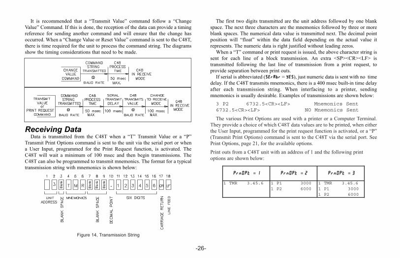
It is recommended that a “Transmit Value” command follow a “Change
Value” Command. If this is done, the reception of the data can provide a timing
reference for sending another command and will ensure that the change has
occurred. When a “Change Value or Reset Value” command is sent to the C48T,
there is time required for the unit to process the command string. The diagrams
show the timing considerations that need to be made.
Receiving DataData is transmitted from the C48T when a “T” Transmit Value or a “P”
Transmit Print Options command is sent to the unit via the serial port or when
a User Input, programmed for the Print Request function, is activated. The
C48T will wait a minimum of 100 msec and then begin transmissions. The
C48T can also be programmed to transmit mnemonics. The format for a typical
transmission string with mnemonics is shown below:
The first two digits transmitted are the unit address followed by one blank
space. The next three characters are the mnemonics followed by three or more
blank spaces. The numerical data value is transmitted next. The decimal point
position will “float” within the data field depending on the actual value it
represents. The numeric data is right justified without leading zeros.
When a “T” command or print request is issued, the above character string is
sent for each line of a block transmission. An extra <SP><CR><LF> is
transmitted following the last line of transmission from a print request, to
provide separation between print outs.
If serial is abbreviated (SErAbr = YES), just numeric data is sent with no time
delay. If the C48T transmits mnemonics, there is a 400 msec built-in time delay
after each transmission string. When interfacing to a printer, sending
mnemonics is usually desirable. Examples of transmissions are shown below:
3 P2 6732.5<CR><LF> Mnemonics Sent6732.5<CR><LF> NO Mnemonics Sent
The various Print Options are used with a printer or a Computer Terminal.
They provide a choice of which C48T data values are to be printed, when either
the User Input, programmed for the print request function is activated, or a “P”
(Transmit Print Options) command is sent to the C48T via the serial port. See
Print Options, page 21, for the available options.
Print outs from a C48T unit with an address of 1 and the following print
options are shown below:
-26-
Figure 14, Transmission String
PrnOPt = 1 PrnOPt = 2 PrnOPt = 3
1 TMR 3.45.6 1 P1 3000 1 TMR 3.45.61 P2 6000 1 P1 3000
1 P2 6000
C48t-im.QXD 3/5/04 3:29 PM Page 26

Serial ConnectionsWhen wiring, refer to the numbers listed on the label with the terminal
description for installing each wire in its proper location.For RS-485, the data (transceiver) wires connect to the A(+) and B(-)
terminals. It is recommended that shielded (screened) cable be used for serialcommunications. In some applications, a signal ground may be required toestablish a ground reference. The signal ground is required if the equipmentdoes not have internal bias resistors connected to the transceiver lines. Ifnecessary, the shield can be used as the signal ground.
TERMINAL DESCRIPTIONSCOMM. - Common required for communication hook-up.A (+) & B (-) - The C48T transmits and receives on these two terminals whichare connected to the external device.
Troubleshooting Serial CommunicationsIf problems are encountered when interfacing the C48T(s) and host device or
printer, the following check list can be used to help find a solution. 1. Check all wiring. Refer to the previous application and use it as a guide tocheck your serial communication wiring. Proper polarity of all C48T(s) andother peripherals must be observed.
2. If the C48T is connected to a “host computer”, device or printer, check tomake sure that the computer or device is configured with the samecommunication format as the C48T. The communication format the C48Twill accept is; 1 start bit, 7 or 8 data bits, no parity or 1 parity bit (odd oreven), and 1 stop bit.
3. Check the baud rate and parity in the Programming Menu SErSEt parameter,and make sure all devices on the line are set to the same baud rate and parity.
4. Check the C48T’s unit address. If the Address command is not used whentransmitting a command to the C48T, the C48T’s address must be set to 0.See Sending Commands & Data, page 24, for command structure.
5. If two-way communications are to be established between the C48T and acomputer, have the computer receive transmissions from the C48T first.Activating a User Input, programmed for the print request function, willinitiate transmissions from the C48T.
6. When sending commands to the C48T, an asterisk * (2AH) must terminatethe command.
7. In multiple unit configurations, make sure each unit has a different addressother than zero. If a transmit value or print request command is issued, anasterisk (*) must be sent before sending another transmission.
8. If all of the above has been done, try reversing the polarity of the transceiverwires between the C48T (s) and the RS485 interface card. Some cards havethe polarity reversed.
-27-

-28-
TO SERIAL PORTON COMPUTER
A(+)B(-)
OFFICE PC(WITH RS485 INTERFACE CARD INSTALLED)
SHIELD
INPUT 2 12+
~AC
14A(+)
RS-485 OPTION
4 +5
AC~11
+
1 13
3 +2 +
B(-)
910
6
87
+ USER INPUT 1
RUN/STOP
USER INPUT 3
COMM.
DC OUT/IN
+
+
++
++++
N/C
O2-SS
COMM.
USER
O1-SS
O2-SS
INPUT 2
N/C
COMM.
O1-SS
8+3 + USER INPUT 3
5 +USER4 +
11 12 +AC~~AC
+ ++DC OUT/IN10COMM.9
RS-485 OPTIONB(-)
12 +
+ + + +
A(+)1413 +
RUN/STOP
USER INPUT 167
O1-SS
COMM.
N/C
INPUT 2
O2-SS
RS-485 OPTION
+3 +
USER +5+4
+1211~AC~AC
+ ++
B(-)
+1+2
+13 14+ ++
A(+)
USER INPUT 38
DC OUT/IN10COMM.9
USER INPUT 1
RUN/STOP67
O2-SS
INPUT 2
N/C
COMM.
O1-SS
O1-SS
COMM.
N/C
INPUT 2
O2-SS
8 USER INPUT 33
USER 5 +4 +
+
AC~12
AC~11 +
+ + ++
DC OUT/IN10COMM.9
RS-485 OPTIONB(-)
1 +2 +
1413 ++ + +
A(+)
RUN/STOP
USER INPUT 167
RS-485 OPTION
+3 +
USER +5+4
+1211~AC~AC
+ ++
B(-)
+1+2
+13 14+ ++
A(+)
USER INPUT 38
DC OUT/IN10COMM.9
USER INPUT 1
RUN/STOP67
O2-SS
INPUT 2
N/C
COMM.
O1-SS
8+3 + USER INPUT 3
5 +USER4 +
11 12 +AC~~AC
+ ++DC OUT/IN10COMM.9
RS-485 OPTIONB(-)
12 +
+ + + +
A(+)1413 +
RUN/STOP
USER INPUT 167
Figure 15, Connecting to a Host Terminal
connection. Each C48T is programmed for a differentaddress and all are programmed for the same baud rateand parity as the computer (ex. 9600 baud, parity even).An application program is written to send and receivedata from the units using the proper commands.
CONNECTING TO A HOST TERMINALSix C48T units are used to monitor and control parts
packaging machines in a plant. C48T units are located ateach machine in the production area of the building. Acommunication line is run to a PC located in theproduction office. The drawing shows the line

One Shot Timing CycleProper wash down mixture for a food processing plant is an important factor
in maintaining the clean environment required. A disinfectant solution is addedto the mixing/holding tank used for the wash down cycle. When the holdingtank is near empty, a level transducer activates the filler pump. A C48TS is usedto turn on the disinfectant solution pump for a preprogrammed amount of timeduring the filling process of the holding tank.
When the filler pump starts, a momentary contact closure activates UserInput 1, resetting the C48 Timer. The timer begins the timing cycle since the runterminal is connected to common. The normally open relay contacts close at thetimer reset signal activating the disinfectant solution pump. When theprogrammed preset is reached, timing stops and the relay deactivates, turningoff the pump controlling the disinfectant solution. The C48 Timer’s preset cycletime may be changed according to the manufacturer’s concentration level of thedisinfectant.
APPLICATION PROGRAMMING
-29-
APPENDIX “A” - APPLICATION EXAMPLE
INPUT 2 12+
~AC
14A(+)
RS-485 OPTION
4 +5
AC~11+
1 13
3 +2
+
B(-)
910
6
87
+ USER INPUT 1
RUN/STOP
USER INPUT 3
COMM.
DC OUT/IN
+
+
++
++++
O1-RLY
O1-RLY
O1-SS
COMM.
USER
ACPOWER
POWERAC
FROM DISINFECTANTSTORAGE TANKOUT TAKE
MAININTAKE
MOMENTARYCLOSURE
LEVELTRANSDUCER
EntrY AutoSc
trAnGE
OPEr 09
rSt.P.uP no
Ac PrS -Y (yes)
PrESEt xxxx.xx
rEVOut -Y (yes)
rEVAnu -n (no)
OutP.uP -F (off)
USrIn1 rSt-E
USrIn2 Pro.diS
USrIn3 ChgdSP
Usr F1 rSt-E
CodE xxx
ScroLL no
n.SEC (min & sec)

1.DISPLAY: 2 Line by 6 digit LCD display; Positive image reflective or negativeimage transmissive with red (top line) and green (bottom line) backlighting.Main Display: 0.3" (7.62 mm) high digitsSecondary Display: 0.2" (5.08 mm) high digitsAnnunciators:
Value: PRS, 1, and 2Output: 01 and 02
2. POWER REQUIREMENTS:AC Versions (C48TXX0X):
AC Power: 85 to 250 VAC, 50/60 Hz, 9 VA max.DC Power: 11 to 14 VDC @ 150 mA max. (Non PNP output models)Note: AC Versions with PNP outputs cannot be powered from DC.
DC Versions (C48TXX1X):CONTINUOUS:
DC Power: 18 to 36 VDC; 5.5 W max.AC Power: 24 VAC ±10%; 50/60 Hz; 7 VA max.Note: The +10% tolerance range on AC input voltage must be strictly
adhered to. DO NOT EXCEED 26.4 VAC.PEAK (START-UP CURRENT):
AC or DC Power: 500 mA peak start-up current for 10 msec max.3. MEMORY: Nonvolatile E2PROM retains all programmable parameters andtimer values.
4. SENSOR POWER: +12 VDC (± 15%) @ 100 mA max.5. INPUTS: Run/Stop, User Input 1, User Input 2, and User Input 3.Configurable as current sinking (active low) or current sourcing (active high)inputs via a single plug jumper.Current Sinking (active low): VIL = 1.5 VDC max, 22 KW pull-up to 5 VDC.
Current Sourcing (active high): VIH = 3.5 VDC min., VIN max = 30 VDC;22 KW pull-down.
Run/Stop Response Time: 250 msec max.User Input Response Time: 5 msec max.
6. TIME ACCURACY: ± 0.01%7. OUTPUTS: (Output type and quantity, model dependent)
Solid-State: NPN Open Collector: ISNK = 100 mA max. @ VOL = 1.1 VDC max;VOH = 30 VDC max.
PNP Open Collector: ISRC = 100 mA max.(See note); VSRC = 12VDC ±15% (using internal supply); VSRC = 13 to 30 VDC max. (usingexternal supply).Note: The internal supply of the C48T can provide a total of 100 mA forthe combination of sensor current and PNP output sourcing current.The supply voltage is +12 VDC (±15%), which will be the PNP outputvoltage level when using only the internal supply.
-30-
APPENDIX “B” - SPECIFICATIONS AND DIMENSIONS
13 14
121110
9
8
7
6
5
4
3
2
1
(49.5)
(49.5)1.95
1.95
4.17 (105.9)0.37(9.4)
(44.7)1.76
1.76 (44.7) 1.772
(45 )1.772
(45 )
+0.024-0.000
+0.6-0.0
+0.024-0.000
+0.6-0.0
F1RST
21 3SRP
302010
DIMENSIONS In inches (mm)PANEL CUT-OUT
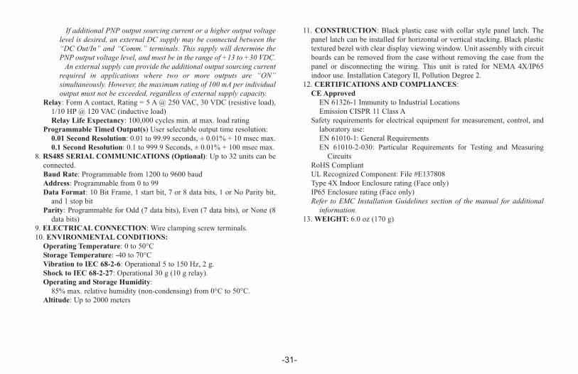
If additional PNP output sourcing current or a higher output voltagelevel is desired, an external DC supply may be connected between the“DC Out/In” and “Comm.” terminals. This supply will determine thePNP output voltage level, and must be in the range of +13 to +30 VDC. An external supply can provide the additional output sourcing current
required in applications where two or more outputs are “ON”simultaneously. However, the maximum rating of 100 mA per individualoutput must not be exceeded, regardless of external supply capacity.
Relay: Form A contact, Rating = 5 A @ 250 VAC, 30 VDC (resistive load),1/10 HP @ 120 VAC (inductive load)Relay Life Expectancy: 100,000 cycles min. at max. load rating
Programmable Timed Output(s) User selectable output time resolution:0.01 Second Resolution: 0.01 to 99.99 seconds, ± 0.01% + 10 msec max.0.1 Second Resolution: 0.1 to 999.9 Seconds, ± 0.01% + 100 msec max.
8. RS485 SERIAL COMMUNICATIONS (Optional): Up to 32 units can beconnected.Baud Rate: Programmable from 1200 to 9600 baudAddress: Programmable from 0 to 99Data Format: 10 Bit Frame, 1 start bit, 7 or 8 data bits, 1 or No Parity bit,and 1 stop bit
Parity: Programmable for Odd (7 data bits), Even (7 data bits), or None (8data bits)
9. ELECTRICAL CONNECTION: Wire clamping screw terminals.10. ENVIRONMENTAL CONDITIONS:
Operating Temperature: 0 to 50°CStorage Temperature: -40 to 70°CVibration to IEC 68-2-6: Operational 5 to 150 Hz, 2 g.Shock to IEC 68-2-27: Operational 30 g (10 g relay).Operating and Storage Humidity:85% max. relative humidity (non-condensing) from 0°C to 50°C.
Altitude: Up to 2000 meters
11. CONSTRUCTION: Black plastic case with collar style panel latch. Thepanel latch can be installed for horizontal or vertical stacking. Black plastictextured bezel with clear display viewing window. Unit assembly with circuitboards can be removed from the case without removing the case from thepanel or disconnecting the wiring. This unit is rated for NEMA 4X/IP65indoor use. Installation Category II, Pollution Degree 2.
12. CERTIFICATIONS AND COMPLIANCES:CE ApprovedEN 61326-1 Immunity to Industrial LocationsEmission CISPR 11 Class A
Safety requirements for electrical equipment for measurement, control, andlaboratory use: EN 61010-1: General RequirementsEN 61010-2-030: Particular Requirements for Testing and MeasuringCircuits
RoHS CompliantUL Recognized Component: File #E137808Type 4X Indoor Enclosure rating (Face only)IP65 Enclosure rating (Face only)Refer to EMC Installation Guidelines section of the manual for additional
information.13. WEIGHT: 6.0 oz (170 g)
-31-

The majority of problems can be traced to improper connections or incorrect set-up parameters. Be sure allconnections are clean and tight, that the correct output board is fitted, and that the set-up parameters are correct. Also,be sure the User Input Plug Jumper position is correct for the particular application. For further technical assistance,contact technical support at www.redlion.net.
-32-
PROBLEMS POSSIBLE CAUSE REMEDIESNO DISPLAY 1. Power off. 1. Verify power.
2. Loose connection or improperly wired. 2. Check connections and wiring.3. Brown out condition. 3. Verify power reading.4. Bezel assembly not fully seated into rear of unit. 4. Check installation.
5. Verify Source current rating.
Err3 DISPLAYED AT POWER UP
Err2 DISPLAYED AT POWER UP
Err1 DISPLAYED AT POWER UP
1. Data error in timer value detected by processor.
1. Data error in programming parameters detected by processor.
1. Data error in preset or output time values detected by processor.
1. Press A key.
1. Press A key.
1. Press A key.2. Check signal lines for possible noise sources.
a. Check all programming parameters.
a. Check presets and output time values.
2. Check signal lines for possible noise sources.
2. Check signal lines for possible noise sources.
UNIT DOES NOT TIME 1. Run/Stop input not active. 1. Check Run/Stop input connections.2. Unit programmed for stop timing at output 1 or 2 mode. 2. Apply reset to restart the timing cycle.1. Front panel disabled. 1. Check “Front Panel Accessible Functions With Program
Disable” section of the manual.CAN NOT ENTER INTOPROGRAMMING
5. If powered by +12 VDC source, not enough current to drive C48.
APPENDIX “C” - TROUBLESHOOTING

-33-
4. Check or replace output board.4. Defective output board.3. Check output board.3. Incorrect output board.2. Check Wiring.2. Improperly wired.1. Install output board.1. Output board not installed.OUTPUTS NOT WORKING
1. Verify programming of the user input parameter.1. User input not properly programmed.
1. Program User input to a level active (maintained) reset.1. User input reset mode set for edge triggered (momentary) reset.
OUTPUT WILL NOT RESET
1. Verify programming of Access presets parameter.1. Front panel disabled.
2. Configure Snk/Src jumper.2. User Input Snk/Src jumper configured improperly.1. Verify programming of User Input parameter.1. User input not properly programmed.TIMER WILL NOT RESET
WHEN A MANUAL RESET ISPERFORMED
REMEDIESPOSSIBLE CAUSEPROBLEMS
PRESETS OR OUTPUT TIMEVALUES CAN BE VIEWEDBUT NOT CHANGED 2. Check “Front Panel Accessible Functions With Program
Disable” section of manual.
UNIT TIMES WHILE RESETIS ACTIVATED
APPENDIX “C” - TROUBLESHOOTING (Cont’d)

-34-
APPENDIX “D” -TERMINAL CONFIGURATIONS FOR C48 TIMERS
12+
~AC
14A(+)
RS-485 OPTION
4 +5
AC~+
1
3 +2
+
B(-)
910
6
87
+ USER INPUT 1
RUN/STOP
USER INPUT 3
COMM.
DC OUT/IN
+
+
++
++++
O1-RLY
O1-RLY
COMM.
USER
O1-SS13
11INPUT 2
12+
14A(+)
RS-485 OPTION
4 +5
+
1
3 +2
+
B(-)
910
6
87
+ USER INPUT 1
RUN/STOP
USER INPUT 3
COMM.
+
+
++
++++
O1-RLY
O1-RLY
COMM.
USER
O1-SS13
11INPUT 2 DC OUT/IN(V IN)SRC
(AC)(AC)DC+ DC-
INPUT 2 12+
14A(+)
RS-485 OPTION
4 +5 11
+
1 13
3 +2
+
B(-)
910
6
87
+ USER INPUT 1
RUN/STOP
USER INPUT 3
COMM.
+
+
++
++++
O1-RLY
O1-RLY
O2-RLY
USER
O2-RLY
DC OUT/IN(V IN)SRC
(AC)(AC)DC+ DC- INPUT 2 12
+
DC-
14A(+)
RS-485 OPTION
4 +5
DC+11+
1 13
3 +2
+
B(-)
910
6
87
+ USER INPUT 1
RUN/STOP
USER INPUT 3
COMM.
DC OUT/IN
+
+
++
++++
N/C
O2-SS
COMM.
USER
O1-SS
(V IN)SRC
(AC) (AC)
C48TS - SINGLE PRESET RELAY AND SOLID-STATE OUTPUTS
C48TS - SINGLE PRESET RELAY AND SOLID-STATE OUTPUTS
INPUT 2 12+
~AC
14A(+)
RS-485 OPTION
4 +5
AC~11
+
1 13
3 +2 +
B(-)
910
6
87
+ USER INPUT 1
RUN/STOP
USER INPUT 3
COMM.
DC OUT/IN
+
+
++
++++
O1-RLY
O1-RLY
O2-RLY
USER
O2-RLY
C48TD - DUAL PRESET RELAY OUTPUTS
C48TD - DUAL PRESET RELAY OUTPUTS
INPUT 2 12+
~AC
14A(+)
RS-485 OPTION
4 +5
AC~11+
1 13
3 +2
+
B(-)
910
6
87
+ USER INPUT 1
RUN/STOP
USER INPUT 3
COMM.
DC OUT/IN
+
+
++
++++
N/C
O2-SS
COMM.
USER
O1-SS
C48TD - DUAL PRESET SOLID-STATE OUTPUTS
C48TD - DUAL PRESET SOLID-STATE OUTPUTS
C48TXX0X VERSIONS (85 TO 250 VAC POWERED)
C48TXX1X VERSIONS (18 TO 36 VDC/24 VAC POWERED)
Caution: Observe proper polarity when connecting DC voltages.Damage to the unit will occur if polarity is reversed.

-35-
APPENDIX “E” - ORDERING INFORMATION
MODEL NO. DESCRIPTION NPN O.C. *OUTPUT(S)
RELAYOUTPUT(S) RS485
REPLACEMENTRELAY OUTPUT
BOARDS85 TO 250 VAC18-36 VDC/24VAC
C48TS1 Preset Timer, Reflective LCD Yes Yes No RBC48001C48TS003C48TS013
C48TD
1 Preset Timer, Backlit LCD Yes Yes No RBC48001C48TS103C48TS1132 Preset Timer, Reflective LCD No Yes No RBC48003C48TD002C48TD0122 Preset Timer, Reflective LCD No Yes Yes RBC48003C48TD007C48TD0172 Preset Timer, Reflective LCD Yes No Yes N/AC48TD005N/A2 Preset Timer, Backlit LCD No Yes No RBC48003C48TD102C48TD1122 Preset Timer, Backlit LCD No Yes Yes RBC48003C48TD107C48TD1172 Preset Timer, Backlit LCD Yes No Yes N/AC48TD105N/A
PART NUMBER FOR AVAILABLESUPPLY VOLTAGES
* PNP O.C. Output(s) versions available. Contact the Factory.

-36-

LIMITED WARRANTY(a) Red Lion Controls Inc. (the “Company”) warrants that all Products shall be free from defects inmaterial and workmanship under normal use for the period of time provided in “Statement of WarrantyPeriods” (available at www.redlion.net) current at the time of shipment of the Products (the “WarrantyPeriod”). EXCEPT FOR THE ABOVE-STATED WARRANTY, COMPANY MAKES NOWARRANTY WHATSOEVER WITH RESPECT TO THE PRODUCTS, INCLUDING ANY (A)WARRANTY OF MERCHANTABILITY; (B) WARRANTY OF FITNESS FOR APARTICULAR PURPOSE; OR (C) WARRANTY AGAINST INFRINGEMENT OFINTELLECTUAL PROPERTY RIGHTS OF A THIRD PARTY; WHETHER EXPRESS ORIMPLIED BY LAW, COURSE OF DEALING, COURSE OF PERFORMANCE, USAGE OFTRADE OR OTHERWISE. Customer shall be responsible for determining that a Product is suitablefor Customer’s use and that such use complies with any applicable local, state or federal law. (b) The Company shall not be liable for a breach of the warranty set forth in paragraph (a) if (i) thedefect is a result of Customer’s failure to store, install, commission or maintain the Product accordingto specifications; (ii) Customer alters or repairs such Product without the prior written consent ofCompany.(c) Subject to paragraph (b), with respect to any such Product during the Warranty Period, Companyshall, in its sole discretion, either (i) repair or replace the Product; or (ii) credit or refund the price ofProduct provided that, if Company so requests, Customer shall, at Company’s expense, return suchProduct to Company.(d) THE REMEDIES SET FORTH IN PARAGRAPH (c) SHALL BE THE CUSTOMER’S SOLEAND EXCLUSIVE REMEDY AND COMPANY’S ENTIRE LIABILITY FOR ANY BREACHOF THE LIMITED WARRANTY SET FORTH IN PARAGRAPH (a).
C48T cover-D_C48TTOCgreen.QXD 6/9/2017 9:41 AM Page 3

C48T/IM - D 06/17DRAWING NO. LP0356
C48T cover-D_C48TTOCgreen.QXD 6/9/2017 9:41 AM Page 4