
C2Prog 1.5 - Manual - TI E2E...
26
C2Prog 1.5 - Manual Table of Contents 1 - Overview............................................................................................................................................... 1 2 - Quick Start............................................................................................................................................ 2 3 - Detailed Description............................................................................................................................. 6 4 - Multi-core Devices.............................................................................................................................. 16 5 - Appendix............................................................................................................................................. 20 1 Overview C2Prog is a flash programming tool for TI C2000™ and MSP430™ MCUs. Rather than relying exclusively on JTAG as the communication interface between the programming tool and the MCU, C2Prog also supports reflashing over RS-232, RS-485, TCP/IP, USB and Controller Area Network (CAN). The programmer is, therefore, well suited for deployment in the field where the JTAG port is typically not accessible. Some salient features of the programmer are: • Support for multiple communication interfaces and protocols • Smart detection of which flash sectors must be erased (or manual section selection if desired) • Automatic 32-bit CRC (Cyclic Redundancy Check) generation and programming (allowing the firmware to verify the flash integrity at MCU bootup) • Compatible with standard Intel Hex file allowing for other data (such as FPGA code) to be programmed into MCU flash • “Extended Hex Files” that can be encrypted and contain all the settings for programming, including the secondary bootloader • “Remote Link Files” for programming extended hex files stored on a server • Command-line interface for generating “extended hex” and “remote link” files • Fast serial communication protocol that works reliably with USB-to-RS232 converters • Support for point-to-point as well as multidrop networks • DTR/RTS control for resetting MCU in bootload mode • Support for Texas Instruments ultra-low-cost XDS100 JTAG emulator • DLL interface for batch programming and integration of C2Prog functionality into other applications (requires “professional” or “integration” license for C2Prog – see our Code-Shop ) Copyright 2006-2013 CodeSkin LLC – all rights reserved 1 of 26
Transcript of C2Prog 1.5 - Manual - TI E2E...

C2Prog 1.5 - ManualTable of Contents 1 - Overview...............................................................................................................................................1
2 - Quick Start............................................................................................................................................2
3 - Detailed Description.............................................................................................................................6
4 - Multi-core Devices..............................................................................................................................16
5 - Appendix.............................................................................................................................................20
1 OverviewC2Prog is a flash programming tool for TI C2000™ and MSP430™ MCUs. Rather than relying exclusively on JTAG as the communication interface between the programming tool and the MCU, C2Prog also supports reflashing over RS-232, RS-485, TCP/IP, USB and Controller Area Network (CAN). The programmer is, therefore, well suited for deployment in the field where the JTAG port is typically not accessible.
Some salient features of the programmer are:
• Support for multiple communication interfaces and protocols• Smart detection of which flash sectors must be erased (or manual section selection if desired) • Automatic 32-bit CRC (Cyclic Redundancy Check) generation and programming (allowing the
firmware to verify the flash integrity at MCU bootup) • Compatible with standard Intel Hex file allowing for other data (such as FPGA code) to be
programmed into MCU flash • “Extended Hex Files” that can be encrypted and contain all the settings for programming,
including the secondary bootloader• “Remote Link Files” for programming extended hex files stored on a server• Command-line interface for generating “extended hex” and “remote link” files• Fast serial communication protocol that works reliably with USB-to-RS232 converters• Support for point-to-point as well as multidrop networks • DTR/RTS control for resetting MCU in bootload mode• Support for Texas Instruments ultra-low-cost XDS100 JTAG emulator • DLL interface for batch programming and integration of C2Prog functionality into other
applications (requires “professional” or “integration” license for C2Prog – see our Code-Shop)
Copyright 2006-2013 CodeSkin LLC – all rights reserved 1 of 26
2 Quick Start
2.1 InstallationThe most recent version of the programmer can be downloaded from the CodeSkin website:
http://www.codeskin.com/C2Prog.html
The application is installed using the Windows installer “setup.exe”. It can also be uninstalled from the control panel similar to other Windows software.
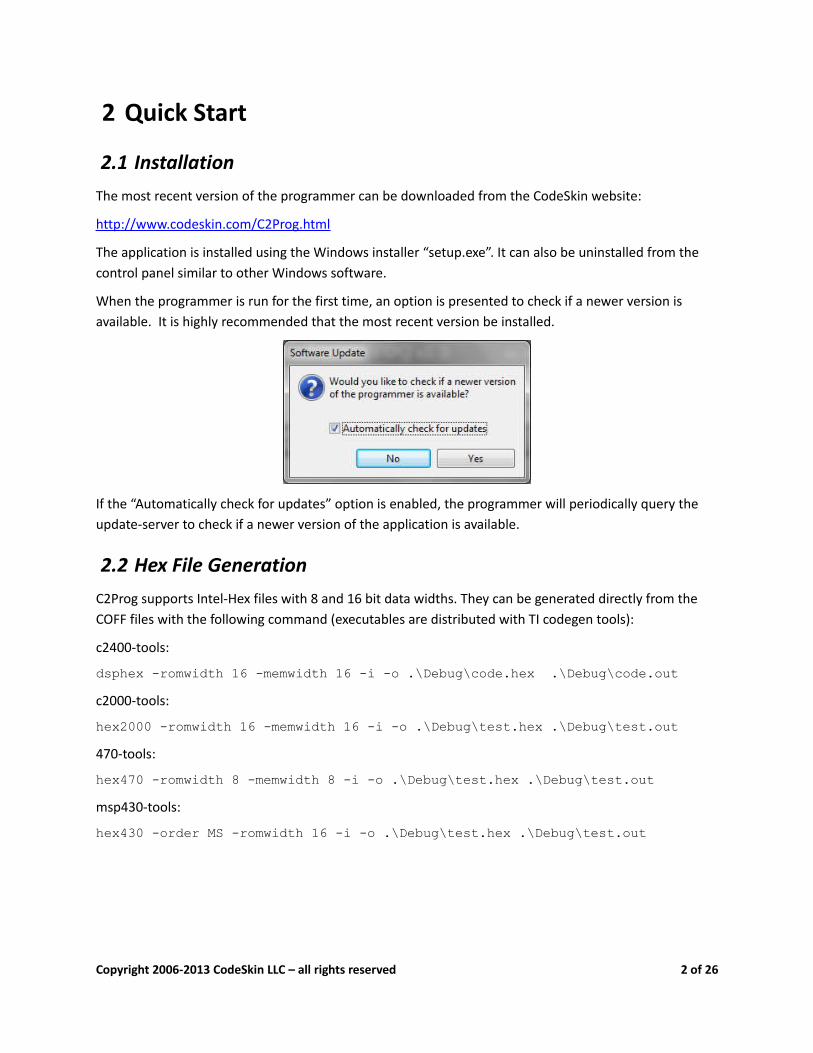
When the programmer is run for the first time, an option is presented to check if a newer version is available. It is highly recommended that the most recent version be installed.
If the “Automatically check for updates” option is enabled, the programmer will periodically query the update-server to check if a newer version of the application is available.
2.2 Hex File GenerationC2Prog supports Intel-Hex files with 8 and 16 bit data widths. They can be generated directly from the COFF files with the following command (executables are distributed with TI codegen tools):
c2400-tools:
dsphex -romwidth 16 -memwidth 16 -i -o .\Debug\code.hex .\Debug\code.outc2000-tools:
hex2000 -romwidth 16 -memwidth 16 -i -o .\Debug\test.hex .\Debug\test.out470-tools:
hex470 -romwidth 8 -memwidth 8 -i -o .\Debug\test.hex .\Debug\test.outmsp430-tools:
hex430 -order MS -romwidth 16 -i -o .\Debug\test.hex .\Debug\test.out
Copyright 2006-2013 CodeSkin LLC – all rights reserved 2 of 26

Note that regular COFF files (*.out) can not be loaded by the programmer – they have to be converted to hex-files first as explained above.
For Code Composer Studio™ users it is recommended that this conversion be configured as a final build step. See Section 3.7 for information on how to directly generate ehx files from CCS.
2.3 Programming (over RS-232)This section demonstrates the use of C2Prog in conjunction with TI's SCI bootloader. Please refer to the TI “Boot ROM Reference Guide” for information on how to configure your target for SCI programming. In order to operate with the C2Prog default settings, it is necessary that the serial link be capable of full duplex communication at 115200 baud. Slower links are supported, but will require custom settings.
In order to program an MCU using C2Prog, first the hex file needs to be selected by means of the “Select File...” button.
An Intel Hex file only contains raw flash data. It does not define any target specific information such as the type of MCU to be programmed, its oscillator frequency, the communication protocol to be used, etc. This information must be configured in the “Programming Configuration” panel.
Copyright 2006-2013 CodeSkin LLC – all rights reserved 3 of 26

First, the target must be selected by choosing the appropriate MCU part-name and option (e.g. clock frequency). Contact CodeSkin at [email protected] if no match is found for your hardware.
For programming a locked C2000™ MCU, valid CSM keys (passwords) have to be entered as 4 digit hex numbers. If the key fields are left at FFFF, C2Prog will attempt to unlock a locked MCU by using the keys embedded in the hex file at the CSM locations. Note that contrary to the other fields, keys are not “remembered” as defaults. The keys are also automatically reset to FFFF whenever the target selection is changed.
Next, the sectors requiring erasing need to be selected. This can either be done manually by checking the individual boxes, or by choosing “Smart Sector Selection”. The smart sector feature automatically detects which sectors need erasing by parsing the contents of the hex file.
As a final option, “Append Checksum” can be selected, which causes the programmer to append a 32-bit CRC checksum to the hex data. This checksum can be used by the MCU to verify the integrity of the flash data, as described later in this document.
Once all the programming configurations are made, the COM port must be configured, either by typing its name directly into the text-field, or clicking on the “Configure Ports...” button. Valid entries for the serial port on the windows platform are COM1, COM2, etc.
Copyright 2006-2013 CodeSkin LLC – all rights reserved 4 of 26

The “Scan Ports” button in the Port Configuration Dialog automatically scans for all available serial ports. Note that on some computers this feature can take a very long time to execute (particularly if Bluetooth COM ports are present).
Now the flash can be programmed by clicking the “Program” button. This will open a new window which displays status information while the programming progresses, as shown below.
Important: Do not interrupt the programming as this can cause the MCU to be permanently locked. Also, do not power-cycle or reset the target during programming.
Copyright 2006-2013 CodeSkin LLC – all rights reserved 5 of 26
3 Detailed Description
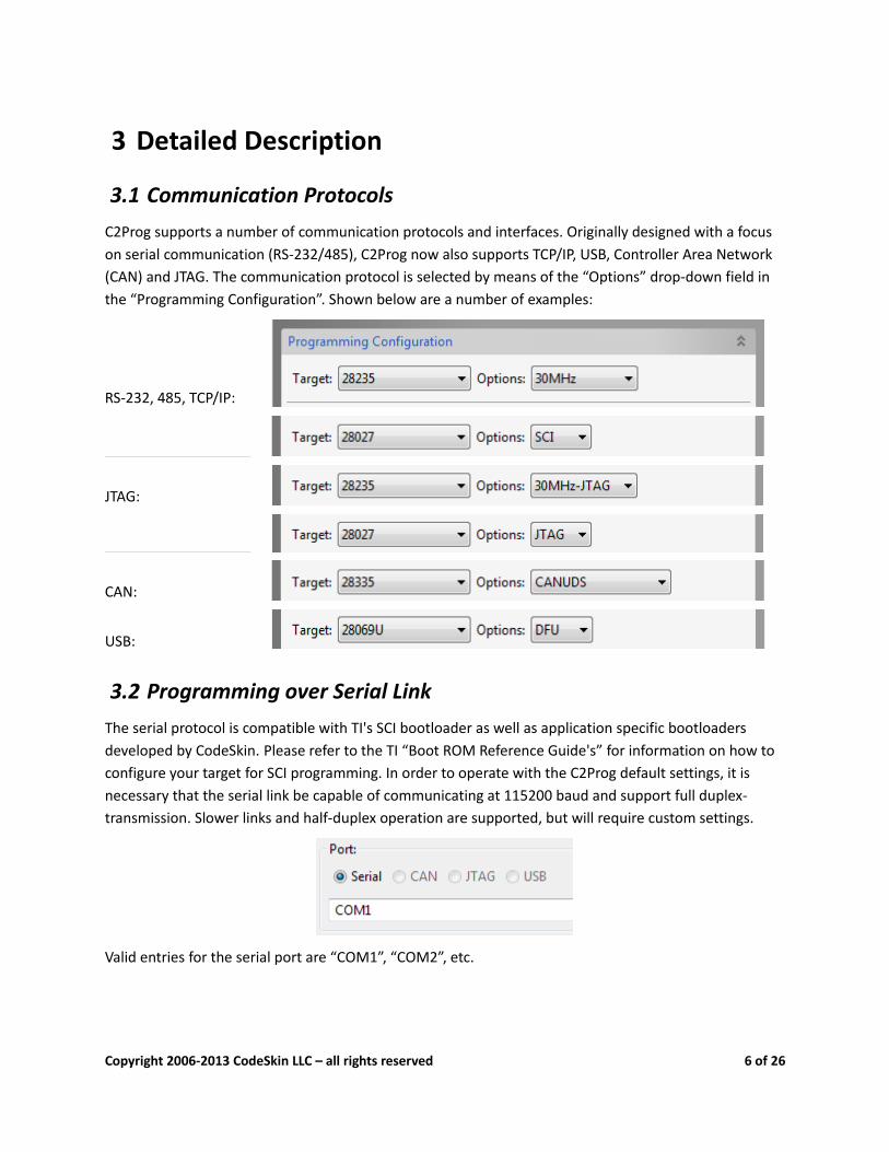
3.1 Communication ProtocolsC2Prog supports a number of communication protocols and interfaces. Originally designed with a focus on serial communication (RS-232/485), C2Prog now also supports TCP/IP, USB, Controller Area Network (CAN) and JTAG. The communication protocol is selected by means of the “Options” drop-down field in the “Programming Configuration”. Shown below are a number of examples:
RS-232, 485, TCP/IP:
JTAG:
CAN:
USB:
3.2 Programming over Serial LinkThe serial protocol is compatible with TI's SCI bootloader as well as application specific bootloaders developed by CodeSkin. Please refer to the TI “Boot ROM Reference Guide's” for information on how to configure your target for SCI programming. In order to operate with the C2Prog default settings, it is necessary that the serial link be capable of communicating at 115200 baud and support full duplex-transmission. Slower links and half-duplex operation are supported, but will require custom settings.
Valid entries for the serial port are “COM1”, “COM2”, etc.
Copyright 2006-2013 CodeSkin LLC – all rights reserved 6 of 26
C2Prog works most reliably with converters that utilize the FTDI chipset. A good choice, for example, is the Parallax USB to Serial Adapter. The serial port of TI's “Experimenter's Kit USB Docking Station” is also proven to work well with C2Prog.
The serial protocol also allows communication over TCP/IP (for example, in conjunction with targets that use Lantronix Serial-to-Ethernet or Serial-to-WiFi converters).
The port configuration string for TCP/IP is “socket:IP:Port”, where “IP” stands for the server IP address, and “Port” is the port of the server, e.g. “socket:192.168.0.100:1001”.
3.3 Programming over JTAGC2Prog currently supports the TI's “Experimenter's Kit USB Docking Station”, “controlSTICKs”, “ez430” as well as the MSP-FET430UIF and XDS100 emulators.
Note that it is extremely important that the correct external clock/crystal frequency is selected, as C2Prog has no means of verifying the frequency when using JTAG. Selecting the wrong frequency may damage the MCU.
For MSP430 JTAG, the port must be configured as either “USBn”, where n is the interface number of the emulator, or “COMx”, where x is the number of the virtual COM port to which the emulator has been mapped.
For C2000 JTAG the port configuration must be formatted as follows:
xds100v<v>:<sn>:<pid>
where <v> must be equal to "1" or "2", <sn> is the serial number of the emulator (in case several are connected), and <pid> is the USB PID of the emulator hardware in hex notation.
Both the <sn> and <pid> parameters are optional. The default value for <pid> is 0xa6d0.
Here are some examples for valid configuration strings:
• “ xds100v1”, or “ xds100v2”
• “xds100v2:TIUDCI83”
• “xds100v2:TIUDCI83:6010”
• “xds100v2::6010”
The serial number of a particular unit can be determined by means of the command-line utility stored in the “common\uscif\ftdi\utility” directory.
Copyright 2006-2013 CodeSkin LLC – all rights reserved 7 of 26

3.4 Programming over USBStellaris® USB-enabled MCUs, such as the 28069U, can be programmed with C2Prog by means of the standard USB Device Firmware Update (DFU) class.
This requires a DFU bootloader to be installed on the target, which implements the Stellaris DFU Binary Protocol Commands. Contact CodeSkin for custom bootloader solutions.
C2Prog expects the following WinUSB GUID for the DFU devices:
D17C772B-AF45-4041-9979-AAFE96BF6398The following syntax is used to configure the USB port:
• “USB”: first DFU device found
• “USBn”: n-th DFU device found
• “USB:sn”: first DFU device found with serial number sn
3.5 Programming over CANC2Prog allows programming over CAN using the “Unified Diagnostics Protocol” as defined in ISO-14229/15765). CAN hardware from Vector, Kvaser and Lawicel is supported1.
The syntax for the port configuration is as follows:
• Lawicel: “canlw:0” - only one port supported
• Kvaser: “cankv:<n>” - where <n> is the port number (0 or 1)
• Vector: “canvec:<n>” - where <n> is the port number (0 or 1)
See notes on bootloaders in Appendix for more information regarding CAN bootloaders, and contact CodeSkin for custom solutions.
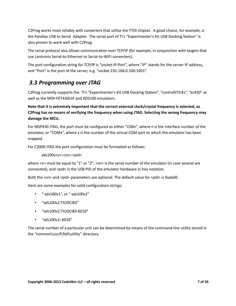
3.6 Programming SequenceThe reflashing process is typically divided into two phases:
• Phase 1: Download of secondary bootloader (SBL)
• Phase 2: Execution of SBL, erasing of flash, download of application / flash programming
The screen capture below further illustrates the programming sequence for the serial mode in conjunction with TI's SCI bootloader. Please refer to the Appendix for more information on bootloaders.
1 All CAN drivers are made available as open source under the GNU Lesser General Public License (LGPL). See http://www.codeskin.com/opensource for more information.
Copyright 2006-2013 CodeSkin LLC – all rights reserved 8 of 26
3.7 Extended Hex FilesThe programming configuration and contents of the Intel Hex file can be combined and saved as an “Extended Hex File” (*.ehx). This format is preferable over the raw hex file, as it allows programming without requiring any manual configuration of the programmer options. An Extended Hex file can also be password protected. It is therefore the ideal format for distributing programming files while avoiding unauthorized use.
From the graphical user interface of the programmer an ehx file can be generated by clicking on the “Create ehx...” button. An even more convenient approach is to automatically generate the ehx file after the hex file as been created from the COFF file. This is easily achieved by calling C2Prog via its command line options, as below:
C2ProgShell.exe -target=28335_30MHz -hex=test.hex -ehx=test.ehxIt is recommended that this command be configured as a final build step, in combination with the hex-file generation. Shown below is a sample batch file named genehx.bat, stored in the root of a C28 CCS project, that can be called as a final build step as follows:
Copyright 2006-2013 CodeSkin LLC – all rights reserved 9 of 26
..\genehx.bat ${C2000_CG_ROOT} ${ProjName}
Sample genehx.batfile:
SET C2PROG_EXE="C:\Program Files (x86)\C2Prog\C2ProgShell.exe"
SET TARGET="F28M35X-C28-512K_20MHz"
SET EHX_OPTIONS=
%1/bin/hex2000 -romwidth 16 -memwidth 16 -i -o %2.hex %2.out
%C2PROG_EXE% -target=%TARGET% %EHX_OPTIONS% -hex=%2.hex -ehx=%2.ehx
This example is configured for the C28 core of a Concerto MCU.
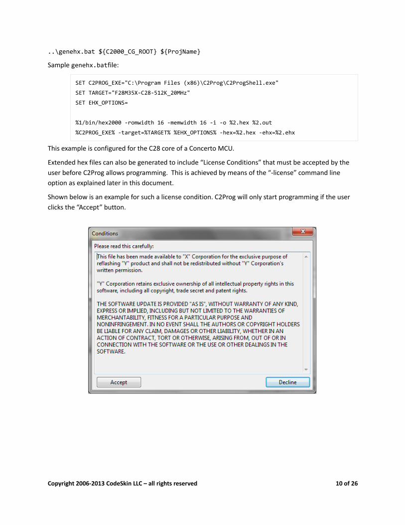
Extended hex files can also be generated to include “License Conditions” that must be accepted by the user before C2Prog allows programming. This is achieved by means of the “-license” command line option as explained later in this document.
Shown below is an example for such a license condition. C2Prog will only start programming if the user clicks the “Accept” button.
Copyright 2006-2013 CodeSkin LLC – all rights reserved 10 of 26
3.8 Remote Hex FilesRemote hex (rhx) files are a means for distributing a link to an ehx-file instead of the actual ehx-file. They are created from the GUI (“Special” menu) or via command line options.
Examples of valid links are:
• file:///c:/file.ehx
• http://hostname/directory/file.ehx
• http://username:password@hostname/directory/file.ehx
• ftp://username:password@hostname/directory/file.ehx
3.9 Command Line OptionsC2Prog can be launched from a command prompt (shell) with command line options. This feature is available to facilitate the creation of ehx and rhx files as part of the code generation (for example, as a “final build step” in Code Composer Studio™. User with a “professional” or “integration” C2Prog license can also program MCUs via the command line. The executable to be called for this mode is “C2ProgShell.exe”.
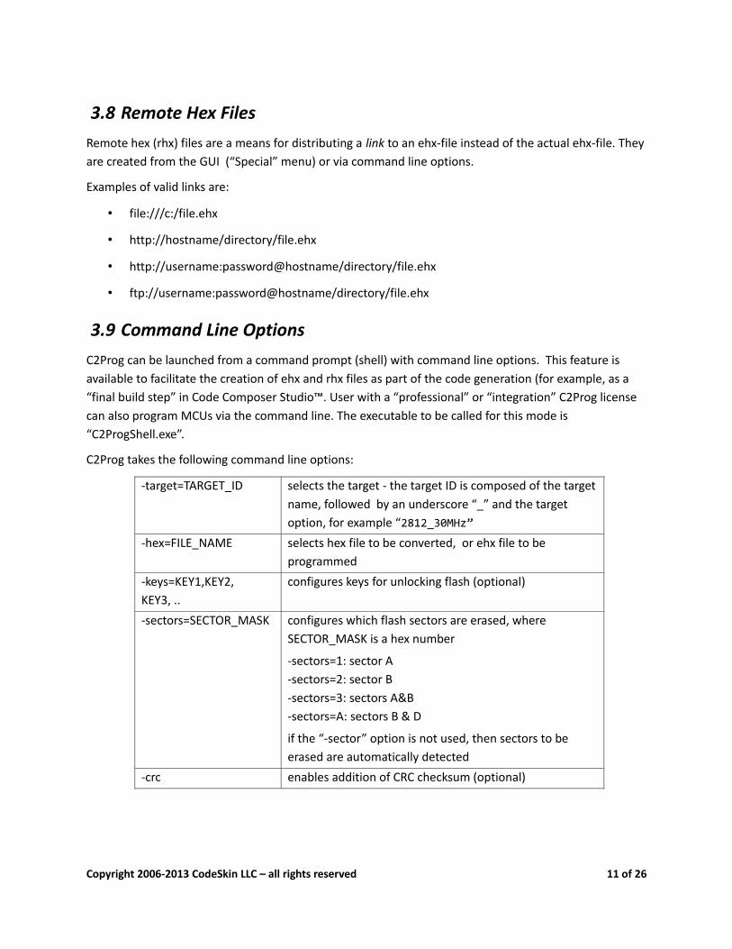
C2Prog takes the following command line options:
-target=TARGET_ID selects the target - the target ID is composed of the target name, followed by an underscore “_” and the target option, for example “2812_30MHz”
-hex=FILE_NAME selects hex file to be converted, or ehx file to be programmed
-keys=KEY1,KEY2, KEY3, ..
configures keys for unlocking flash (optional)
-sectors=SECTOR_MASK configures which flash sectors are erased, where SECTOR_MASK is a hex number
-sectors=1: sector A-sectors=2: sector B-sectors=3: sectors A&B-sectors=A: sectors B & D
if the “-sector” option is not used, then sectors to be erased are automatically detected
-crc enables addition of CRC checksum (optional)
Copyright 2006-2013 CodeSkin LLC – all rights reserved 11 of 26
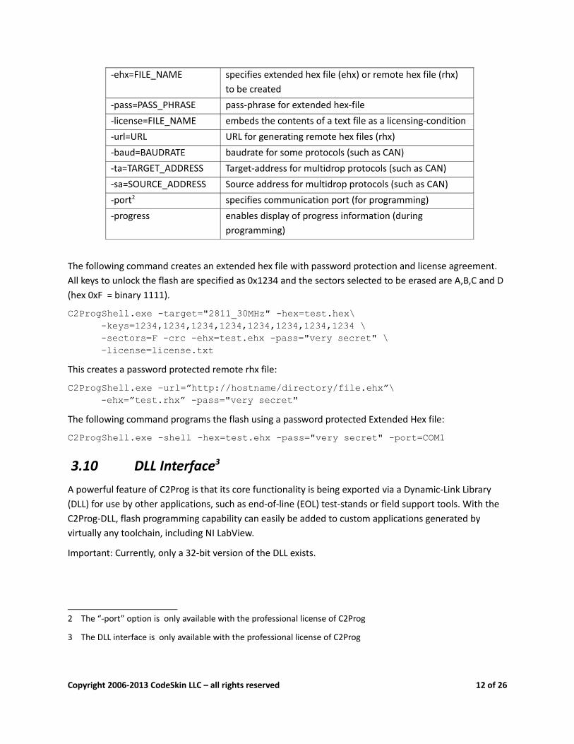
-ehx=FILE_NAME specifies extended hex file (ehx) or remote hex file (rhx) to be created
-pass=PASS_PHRASE pass-phrase for extended hex-file-license=FILE_NAME embeds the contents of a text file as a licensing-condition-url=URL URL for generating remote hex files (rhx)-baud=BAUDRATE baudrate for some protocols (such as CAN)-ta=TARGET_ADDRESS Target-address for multidrop protocols (such as CAN)-sa=SOURCE_ADDRESS Source address for multidrop protocols (such as CAN)-port2 specifies communication port (for programming)-progress enables display of progress information (during
programming)
The following command creates an extended hex file with password protection and license agreement. All keys to unlock the flash are specified as 0x1234 and the sectors selected to be erased are A,B,C and D (hex 0xF = binary 1111).
C2ProgShell.exe -target="2811_30MHz" -hex=test.hex\-keys=1234,1234,1234,1234,1234,1234,1234,1234 \-sectors=F -crc -ehx=test.ehx -pass="very secret" \–license=license.txt
This creates a password protected remote rhx file:
C2ProgShell.exe –url=”http://hostname/directory/file.ehx”\ -ehx=”test.rhx” -pass="very secret"The following command programs the flash using a password protected Extended Hex file:
C2ProgShell.exe -shell -hex=test.ehx -pass="very secret" -port=COM1
3.10 DLL Interface3
A powerful feature of C2Prog is that its core functionality is being exported via a Dynamic-Link Library (DLL) for use by other applications, such as end-of-line (EOL) test-stands or field support tools. With the C2Prog-DLL, flash programming capability can easily be added to custom applications generated by virtually any toolchain, including NI LabView.
Important: Currently, only a 32-bit version of the DLL exists.
2 The “-port” option is only available with the professional license of C2Prog
3 The DLL interface is only available with the professional license of C2Prog
Copyright 2006-2013 CodeSkin LLC – all rights reserved 12 of 26
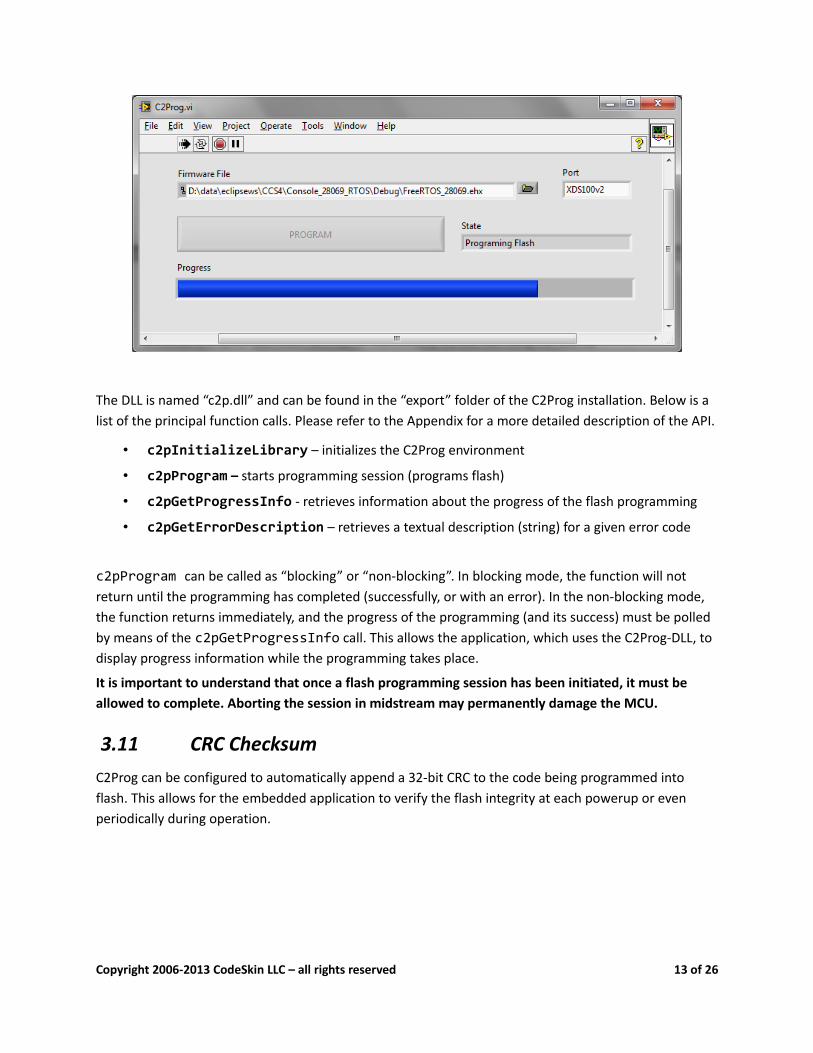
The DLL is named “c2p.dll” and can be found in the “export” folder of the C2Prog installation. Below is a list of the principal function calls. Please refer to the Appendix for a more detailed description of the API.
• c2pInitializeLibrary – initializes the C2Prog environment
• c2pProgram – starts programming session (programs flash)
• c2pGetProgressInfo - retrieves information about the progress of the flash programming
• c2pGetErrorDescription – retrieves a textual description (string) for a given error code
c2pProgram can be called as “blocking” or “non-blocking”. In blocking mode, the function will not return until the programming has completed (successfully, or with an error). In the non-blocking mode, the function returns immediately, and the progress of the programming (and its success) must be polled by means of the c2pGetProgressInfo call. This allows the application, which uses the C2Prog-DLL, to display progress information while the programming takes place.
It is important to understand that once a flash programming session has been initiated, it must be allowed to complete. Aborting the session in midstream may permanently damage the MCU.
3.11 CRC ChecksumC2Prog can be configured to automatically append a 32-bit CRC to the code being programmed into flash. This allows for the embedded application to verify the flash integrity at each powerup or even periodically during operation.
Copyright 2006-2013 CodeSkin LLC – all rights reserved 13 of 26
0x0000
0x0040
0x0044CSM
Last Word of Code
Code
32-bit CRC0x0000
0xFFFF
240x
0x3F7F80
0x3F7FFFCSM
(and entrypoint)
Last Word of Code
Code
32-bit CRC0x0000
0xFFFF
28xx
First Word of Code
CR
C C
heck Stream
CR
C C
heck Stream
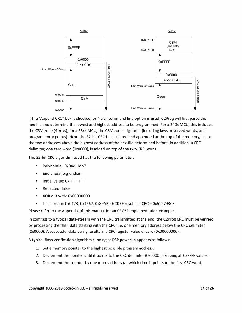
If the “Append CRC” box is checked, or “-crc” command line option is used, C2Prog will first parse the hex-file and determine the lowest and highest address to be programmed. For a 240x MCU, this includes the CSM zone (4 keys), for a 28xx MCU, the CSM zone is ignored (including keys, reserved words, and program entry points). Next, the 32-bit CRC is calculated and appended at the top of the memory, i.e. at the two addresses above the highest address of the hex-file determined before. In addition, a CRC delimiter, one zero word (0x0000), is added on top of the two CRC words.
The 32-bit CRC algorithm used has the following parameters:
• Polynomial: 0x04c11db7
• Endianess: big-endian
• Initial value: 0xFFFFFFFF
• Reflected: false
• XOR out with: 0x00000000
• Test stream: 0x0123, 0x4567, 0x89AB, 0xCDEF results in CRC = 0x612793C3
Please refer to the Appendix of this manual for an CRC32 implementation example.
In contrast to a typical data-stream with the CRC transmitted at the end, the C2Prog CRC must be verified by processing the flash data starting with the CRC, i.e. one memory address below the CRC delimiter (0x0000). A successful data-verify results in a CRC register value of zero (0x00000000).
A typical flash verification algorithm running at DSP powerup appears as follows:
1. Set a memory pointer to the highest possible program address.
2. Decrement the pointer until it points to the CRC delimiter (0x0000), skipping all 0xFFFF values.
3. Decrement the counter by one more address (at which time it points to the first CRC word).
Copyright 2006-2013 CodeSkin LLC – all rights reserved 14 of 26
4. Initialize the CRC register to 0xFFFFFFFF.
5. Update the register with the value addressed by the memory pointer (CRC polynomial: 0x04C11DB7).
6. Decrement memory pointer.
7. Repeat 5-6 until the memory pointer reaches the lowest program address.
8. If, at this point, the register holds 0x00000000, then the data integrity has been successfully verified.
Sample Code for 28xx with code in flash sector A:
#define FLASH_TOP (const Uint16*)(0x3F7F7FL)
#define FLASH_BOT (const Uint16*)(0x3F6000L)
const Uint16* FlashPtr;
Uint32 CRCRegister;
FlashPtr = FLASH_TOP;
// search for CRC delimiter
while((*FlashPtr != 0x0000) && (FlashPtr > FLASH_BOT)){
FlashPtr--;
}
// process stream, CRC first
CRCRegister = 0xFFFFFFFFL;
while(FlashPtr > FLASH_BOT){
FlashPtr--;
// each CRC32Step() shifts one byte into the CRC register
CRCRegister = CRC32Step4(((*FlashPtr >> 8) & 0xFF), CRCRegister);
CRCRegister = CRC32Step(((*FlashPtr >> 0) & 0xFF), CRCRegister);
}
// at this point CRCRegister should be reading zero
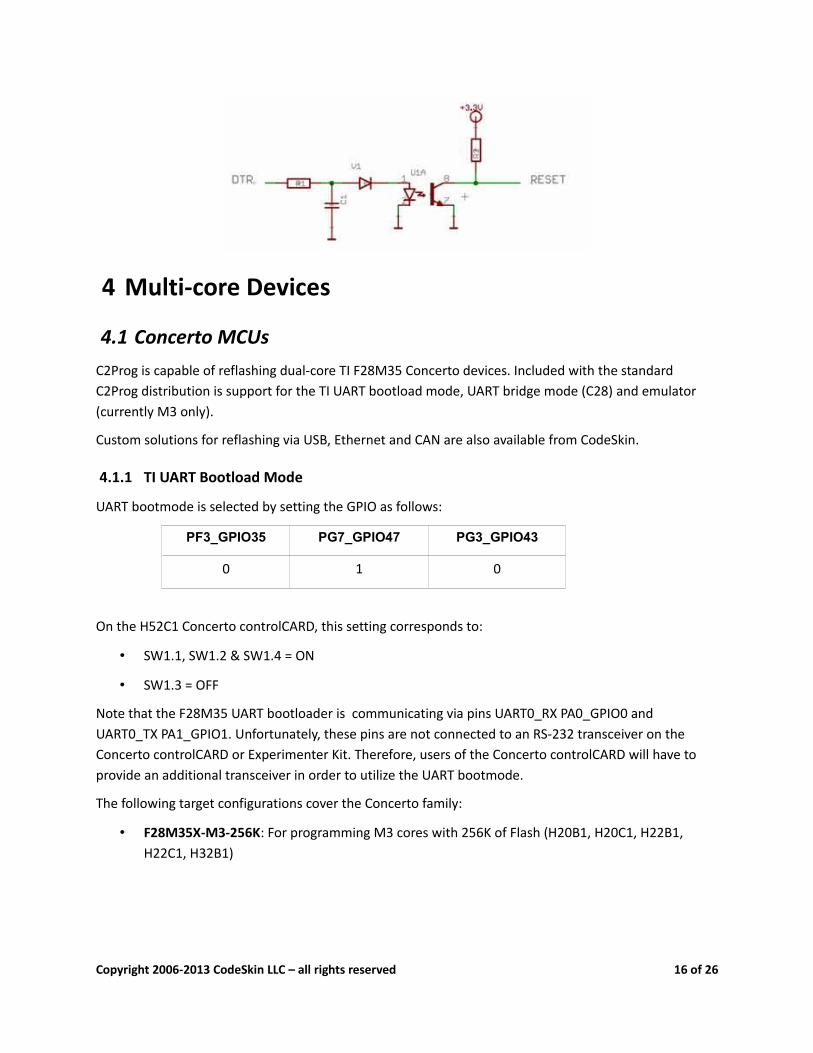
3.12 RTS/DTR ControlRTS/DTR control allows C2Prog to select bootload mode (using RTS) and reset the target (using DTR). In order to use this feature, the hardware must be setup so that a positive DTR line resets the target and a positive RTS selects bootload mode.
Below is an example of how such a control can be implemented.
4 See Appendix for implementation example
Copyright 2006-2013 CodeSkin LLC – all rights reserved 15 of 26
4 Multi-core Devices
4.1 Concerto MCUsC2Prog is capable of reflashing dual-core TI F28M35 Concerto devices. Included with the standard C2Prog distribution is support for the TI UART bootload mode, UART bridge mode (C28) and emulator (currently M3 only).
Custom solutions for reflashing via USB, Ethernet and CAN are also available from CodeSkin.
4.1.1 TI UART Bootload Mode
UART bootmode is selected by setting the GPIO as follows:
PF3_GPIO35 PG7_GPIO47 PG3_GPIO43
0 1 0
On the H52C1 Concerto controlCARD, this setting corresponds to:
• SW1.1, SW1.2 & SW1.4 = ON
• SW1.3 = OFF
Note that the F28M35 UART bootloader is communicating via pins UART0_RX PA0_GPIO0 and UART0_TX PA1_GPIO1. Unfortunately, these pins are not connected to an RS-232 transceiver on the Concerto controlCARD or Experimenter Kit. Therefore, users of the Concerto controlCARD will have to provide an additional transceiver in order to utilize the UART bootmode.
The following target configurations cover the Concerto family:
• F28M35X-M3-256K: For programming M3 cores with 256K of Flash (H20B1, H20C1, H22B1, H22C1, H32B1)
Copyright 2006-2013 CodeSkin LLC – all rights reserved 16 of 26

• F28M35X-M3-512K: For programming M3 cores with 512K of Flash (H32C1, H50B1, H50C1, H52B1, H52C1)
• F28M35X-C28-256K: For programming C28 cores with 256K of Flash (H20B1, H20C1, H22B1, H22C1, H32C1)
• F28M35X-C28-512K: For programming C28 cores with 512K of Flash (H32B1, H50B1, H50C1, H52B1, H52C1)
With these configurations, it is possible to program cores individually. When choosing a Concerto target, it is important that the correct external clock frequency be selected. Currently, only 20 MHz configurations are provided.
Both Concerto cores can be programmed without the need for resetting the device after the first core has been reflashed. This is achieved by first programming the C28 core, and subsequently selecting the “after-C28” option for the M3 target. This process can be automated by using the C2Prog DLL or command-line interface.
Sample batch file for programming both cores in one session:
SET C2PROG_EXE="C:\Program Files (x86)\C2Prog\C2ProgShell.exe"
SET PORT="COM5"
SET C28_EHX_FILE="blinky_dc_c28.ehx"
SET M3_EHX_FILE="blinky_dc_m3.ehx"
%C2PROG_EXE% -hex=%C28_EHX_FILE% -port=%PORT% -progress
%C2PROG_EXE% -hex=%M3_EHX_FILE% -port=%PORT% -progress
PAUSE -1
Commands for generating ehx files:
%C2PROG_EXE% -target="F28M35X-C28-512K_20MHz" -hex=blinky_dc_c28.hex -ehx=blinky_dc_c28.ehx
%C2PROG_EXE% -target="F28M35X-M3-512K_20MHz-after-C28" -hex=blinky_dc_m3.hex -ehx=blinky_dc_m3.ehx
Note that the “after-C28” option is used for the M3 ehx file.
4.1.2 UART Bridge Mode
The UART bridge mode allows for fast and easy reflashing of the C28 core over the M3 UART0 using CodeSkin's “C28-Loader and Development Framework” application. Serial communication between the
Copyright 2006-2013 CodeSkin LLC – all rights reserved 17 of 26

M3 core and C2Prog occurs over pins PIO E4 and E5, which on the Concerto F28M52 ControlCARD can be conveniently accessed as a virtual communication port (VCP).
The M3 application for the C28-Loader and Development Framework is available for download at no charge using an SVN client (e.g. Subclipse) from the following URL:
http://svn.codeskin.com/pub/c2000/CCSv5/concerto/c28_m3uart_loader
The C2Prog target configurations compatible with this loader are the following:
• F28M35X-C28-256K_UART-Bridge: C28 cores with 256K of Flash
• F28M35X-C28-512K_UART-Bridge: C28 cores with 512K of Flash
The C28-Loader and Development Framework contains all the necessary code to reflash the C28 core (encapsulated in a proprietary CodeSkin's library).
After powerup, the M3 core launches the C28 core and services the UART communication port. When commands from C2Prog are received, the application places the C28 core into reflashing mode. After successful completion of the reflashing, the C28 core is launched again in normal mode. Note that with this framework it is not necessary to reset the MCU in order to update and relaunch the C28 core.
The purpose of the framework is primarily to simplify the development of the C28 code, allowing rapid download of C28 applications without the need for a multistage emulator procedure.
The user can modify the application, for example to allow the C28 core access to specific GPIO pins. Note, however, that at this point, only the following C28 clock frequencies are valid (i.e. supported by the C28 reflashing engine): 60 MHz, 100 MHz, 150 MHz.
It is extremely important that the C28_CLK_MHZ macro be properly configured. Setting it to the wrong frequency may damage the MCU.
A typical work-flow using C28-Loader and Development Framework is as follows:
1. Update any C28 I/O configuration in main_m3 (if necessary)
2. Compile application and program M3 core
3. Launch M3 core
4. Compile C28 application and flash using C2Prog (“UART-Bridge” option)
5. Test and debug C28 applications
6. Modify C28 application
7. If no changes to M3 side are necessary, go to step 4), else repeat from 1)
Contact CodeSkin at [email protected] if you are interested in purchasing the source code of the entire application, including the proprietary reflashing library. CodeSkin also offers loaders for reflashing the M3 core.
Copyright 2006-2013 CodeSkin LLC – all rights reserved 18 of 26

4.1.3 JTAG Emulator Mode
The M3 core can be reflashed by means of an XDS100 compatible emulator by selecting the “<X>MHz-JTAG” target option, where <X> identifies the external clock/crystal frequency.
See Section 3.3 for more information about configuring the JTAG port.
Note that it is extremely important that the correct external clock/crystal frequency is selected, as C2Prog has no means of verifying the frequency when using JTAG. Selecting the wrong frequency may damage the MCU.
4.1.4 Concerto Limitations
Currently, C2Prog does not provide Concerto support for the M3 Code Security Module (CSM). Furthermore, the CRC generation is disabled for the M3. Also, OTP programming is disabled for both cores.
Copyright 2006-2013 CodeSkin LLC – all rights reserved 19 of 26
5 Appendix
5.1 LicenseExcept where otherwise noted, all of the documentation and software included in the C2Prog package is copyrighted by CodeSkin, LLC.
Copyright (C) 2006-2013 CodeSkin, LLC. All rights reserved.
A free, limited-feature, Basic License is granted to anyone to use this software for any legal purpose, including commercial applications. Note however, that C2Prog is not designed or suited for use in safety-critical environments, such as, but not limited to, life-support, medical and nuclear applications.
User must review and accept the detailed licensing conditions as stated in the file "C2Prog License.pdf" located in the "doc" folder of the C2Prog installation.
THE SOFTWARE IS PROVIDED "AS IS", WITHOUT WARRANTY OF ANY KIND, EXPRESS OR IMPLIED, INCLUDING BUT NOT LIMITED TO THE WARRANTIES OF MERCHANTABILITY, FITNESS FOR A PARTICULAR PURPOSE AND NONINFRINGEMENT. IN NO EVENT SHALL THE AUTHORS OR COPYRIGHT HOLDERS BE LIABLE FOR ANY CLAIM, DAMAGES OR OTHER LIABILITY, WHETHER IN AN ACTION OF CONTRACT, TORT OR OTHERWISE, ARISING FROM, OUT OF OR IN CONNECTION WITH THE SOFTWARE OR THE USE OR OTHER DEALINGS IN THE SOFTWARE.
5.2 Customizing C2ProgThe principal C2Prog configuration file is “targets.xml” in the “targets” folder. It contains a description of all targets that are supported by the programmer as well as some baudrate and timing options. Limited customization of this file is possible – please contact codeskin.com for more details. The programmer will also parse a file named “targets.custom.xml”, if present. It is recommended that “targets.xml” be renamed to “targets.custom.xml” before any customization is made. This ensures that a reinstall or upgrade of the tool, which preserves “targets.custom.xml”, will not erase those custom settings.
C2Prog also parses the user directory as an alternate location for storing target configuration files. On a Windows machine, this corresponds to the following location:
XP: C:\Documents and Settings\username\codeskin\targets
Vista/Windows-7: C:\users\username\codeskin\targets
Copyright 2006-2013 CodeSkin LLC – all rights reserved 20 of 26
5.3 About BootloadersWhen programming, C2Prog is interacting with a so called “bootloader” running on the target. This bootloader is often divided into two components:
• Primary Bootloader (PBL): The primary bootloader is a small piece of code that is permanently programmed into the target and called immediately after reset. The primary bootloader can branch to the application code (if present) or receive the secondary bootloader (SBL) into RAM over the communication link and execute it. The primary bootloader typically also includes a security algorithm for unlocking the chip before the secondary bootloader can be loaded.
• Secondary Bootloader (SBL): Contrary to the primary bootloader, the secondary bootloader is not permanently stored in the target. Instead, it is being loaded via the primary bootloader when needed. The SBL contains the flash programming algorithms. It erases the flash, receives the application code over the communication link, and programs the flash memory. After the programming is complete, the secondary bootloader can reset the chip.
There are several advantages to dividing the bootloader into two separate parts:
1. Since the primary bootloader does not include flash programming algorithms it can have a small footprint. Due to its low level of complexity it can be validated to a high level of confidence before it is shipped with a product.
2. The secondary bootloader contains the more complex algorithms. However, since it is not permanently programmed into the target, but rather distributed with the programming tool, it can be updated easily if needed.
3. Not having any flash programming algorithms permanently programmed in the target can be considered safer in case of rogue behavior of the application code.
Almost all C2000™ MCU ship with a primary bootloader programmed into the boot-ROM. While this bootloader is supporting several communication interfaces, only the SCI mode (RS-232) is of practical use in the field (the CAN implementation is too limited). CodeSkin has developed secondary RS-232 bootloaders for most C2000™ MCUs and distributes them with the C2Prog programming tool. The compiled versions of the secondary bootloaders are free; if so desired, the source code can be licensed for a fee.
CodeSkin has also developed custom primary bootloaders that can be used in lieu of the TI version. They are licensed as source code, and allow for the implementation of customer specific features, such as servicing an external watchdog, and proprietary security algorithms. The CodeSkin primary bootloaders also support communication protocols other than RS-232. For example half-duplex RS-485 and CAN bus. Along with the primary bootloader, the source code of a matching secondary bootloader is provided.
Copyright 2006-2013 CodeSkin LLC – all rights reserved 21 of 26
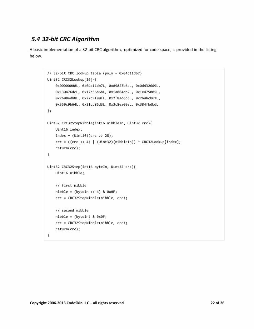
5.4 32-bit CRC AlgorithmA basic implementation of a 32-bit CRC algorithm, optimized for code space, is provided in the listing below.
// 32-bit CRC lookup table (poly = 0x04c11db7)
Uint32 CRC32Lookup[16]={
0x00000000L, 0x04c11db7L, 0x09823b6eL, 0x0d4326d9L,
0x130476dcL, 0x17c56b6bL, 0x1a864db2L, 0x1e475005L,
0x2608edb8L, 0x22c9f00fL, 0x2f8ad6d6L, 0x2b4bcb61L,
0x350c9b64L, 0x31cd86d3L, 0x3c8ea00aL, 0x384fbdbdL
};
Uint32 CRC32StepNibble(int16 nibbleIn, Uint32 crc){
Uint16 index;
index = (Uint16)(crc >> 28);
crc = ((crc << 4) | (Uint32)(nibbleIn)) ^ CRC32Lookup[index];
return(crc);
}
Uint32 CRC32Step(int16 byteIn, Uint32 crc){
Uint16 nibble;
// first nibble
nibble = (byteIn >> 4) & 0x0F;
crc = CRC32StepNibble(nibble, crc);
// second nibble
nibble = (byteIn) & 0x0F;
crc = CRC32StepNibble(nibble, crc);
return(crc);
}
Copyright 2006-2013 CodeSkin LLC – all rights reserved 22 of 26
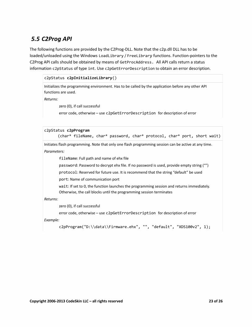
5.5 C2Prog APIThe following functions are provided by the C2Prog-DLL. Note that the c2p.dll DLL has to be loaded/unloaded using the Windows LoadLibrary / FreeLibrary functions. Function-pointers to the C2Prog API calls should be obtained by means of GetProcAddress. All API calls return a status information c2pStatus of type int. Use c2pGetErrorDescription to obtain an error description.
c2pStatus c2pInitializeLibrary()
Initializes the programming environment. Has to be called by the application before any other API functions are used.
Returns:
zero (0), if call successful
error code, otherwise – use c2pGetErrorDescription for description of error
c2pStatus c2pProgram(char* fileName, char* password, char* protocol, char* port, short wait)
Initiates flash programming. Note that only one flash programming session can be active at any time.
Parameters:
fileName: Full path and name of ehx file
password: Password to decrypt ehx file. If no password is used, provide empty string (“”)
protocol: Reserved for future use. It is recommend that the string “default” be used
port: Name of communication port
wait: If set to 0, the function launches the programming session and returns immediately. Otherwise, the call blocks until the programming session terminates
Returns:
zero (0), if call successful
error code, otherwise – use c2pGetErrorDescription for description of error
Example:
c2pProgram("D:\\data\\Firmware.ehx", "", "default", "XDS100v2", 1);
Copyright 2006-2013 CodeSkin LLC – all rights reserved 23 of 26
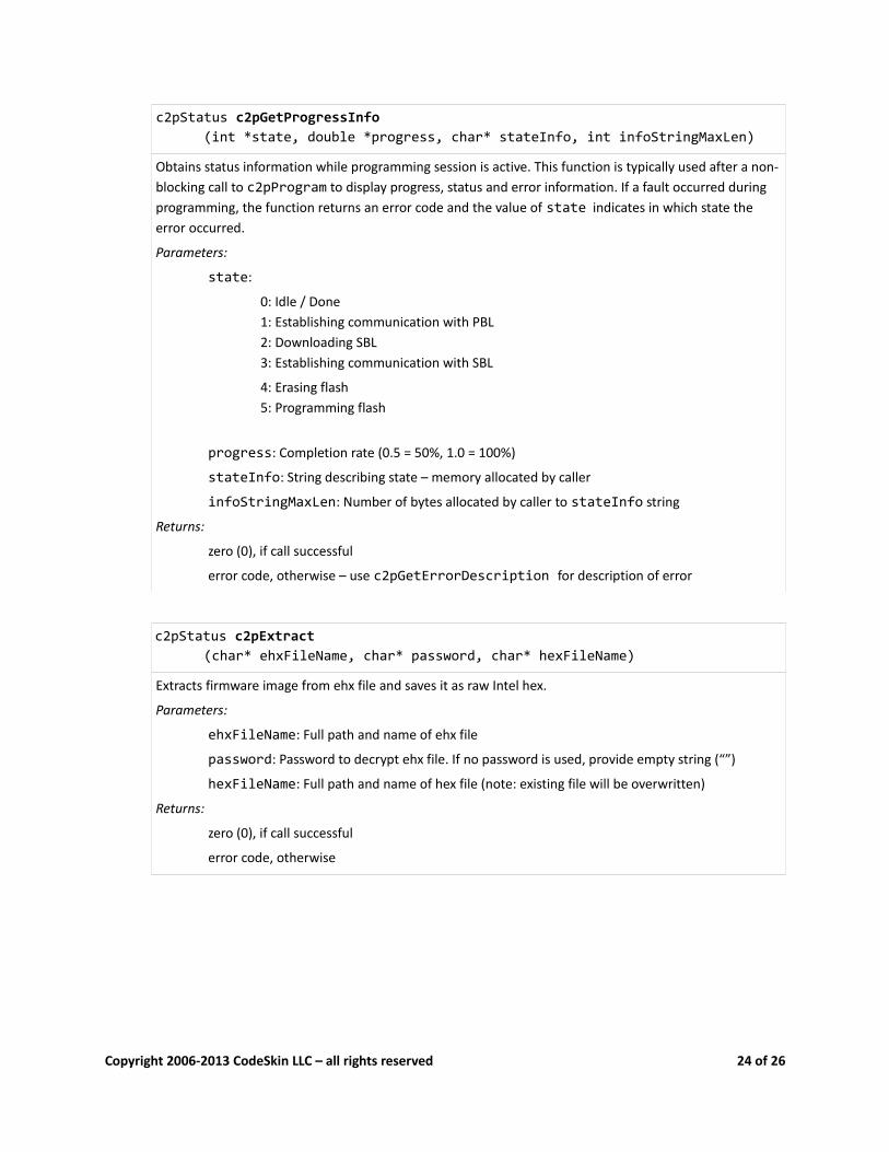
c2pStatus c2pGetProgressInfo(int *state, double *progress, char* stateInfo, int infoStringMaxLen)
Obtains status information while programming session is active. This function is typically used after a non-blocking call to c2pProgram to display progress, status and error information. If a fault occurred during programming, the function returns an error code and the value of state indicates in which state the error occurred.
Parameters:
state:
0: Idle / Done1: Establishing communication with PBL2: Downloading SBL3: Establishing communication with SBL
4: Erasing flash5: Programming flash
progress: Completion rate (0.5 = 50%, 1.0 = 100%)
stateInfo: String describing state – memory allocated by caller
infoStringMaxLen: Number of bytes allocated by caller to stateInfo string
Returns:
zero (0), if call successful
error code, otherwise – use c2pGetErrorDescription for description of error
c2pStatus c2pExtract(char* ehxFileName, char* password, char* hexFileName)
Extracts firmware image from ehx file and saves it as raw Intel hex.
Parameters:
ehxFileName: Full path and name of ehx file
password: Password to decrypt ehx file. If no password is used, provide empty string (“”)
hexFileName: Full path and name of hex file (note: existing file will be overwritten)
Returns:
zero (0), if call successful
error code, otherwise
Copyright 2006-2013 CodeSkin LLC – all rights reserved 24 of 26
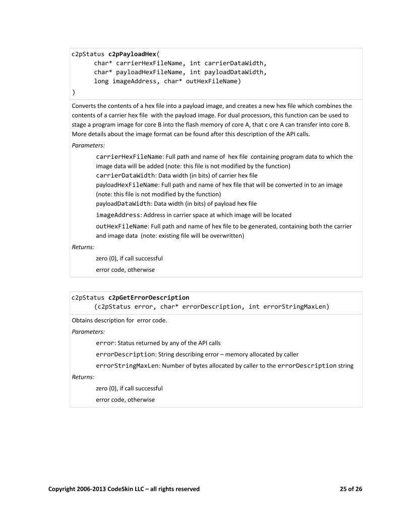
c2pStatus c2pPayloadHex(char* carrierHexFileName, int carrierDataWidth,char* payloadHexFileName, int payloadDataWidth,long imageAddress, char* outHexFileName)
)
Converts the contents of a hex file into a payload image, and creates a new hex file which combines the contents of a carrier hex file with the payload image. For dual processors, this function can be used to stage a program image for core B into the flash memory of core A, that c ore A can transfer into core B. More details about the image format can be found after this description of the API calls.
Parameters:
carrierHexFileName: Full path and name of hex file containing program data to which the image data will be added (note: this file is not modified by the function)carrierDataWidth: Data width (in bits) of carrier hex filepayloadHexFileName: Full path and name of hex file that will be converted in to an image (note: this file is not modified by the function)payloadDataWidth: Data width (in bits) of payload hex file
imageAddress: Address in carrier space at which image will be located
outHexFileName: Full path and name of hex file to be generated, containing both the carrier and image data (note: existing file will be overwritten)
Returns:
zero (0), if call successful
error code, otherwise
c2pStatus c2pGetErrorDescription(c2pStatus error, char* errorDescription, int errorStringMaxLen)
Obtains description for error code.
Parameters:
error: Status returned by any of the API calls
errorDescription: String describing error – memory allocated by caller
errorStringMaxLen: Number of bytes allocated by caller to the errorDescription string
Returns:
zero (0), if call successful
error code, otherwise
Copyright 2006-2013 CodeSkin LLC – all rights reserved 25 of 26

5.5.1 Payload Image Format
The image created by the c2pPayloadHex command consist of a sequence of N Data Records followed by a Termination Record.
Firmware Image
Data Record #0 Data Record #1 Data Record #2 ... Data Record #N-1 Termination Record
n0 bytes n1 bytes n2 bytes nN-1 bytes 4 bytes
Data Records are formatted as follows:
Data Record
Record Data Length k (measured in bytes)
Record Data CRC
2 bytes k bytes 2 bytes
The CRC is a 16-bit value calculated over entire Data Packet (k+2 bytes) (CCITT polynomial: x^16+x^12+x^5+1, initial value = 0xFFFF). All values are stored in Big Endian notation, starting with the most significant byte (MSB).
The Record Data contains image data as well as the address to which the data needs to be copied when the image is deployed (target address).
Record Data
Target address Data
4 bytes k-4 bytes
The Termination Record has a length of 4 bytes:
Termination Record
Record Data Length k (measured in bytes)
CRC
0x0000 0x1D0F
Copyright 2006-2013 CodeSkin LLC – all rights reserved 26 of 26


![f a reassembled PDU] - Texas Instrumentse2e.ti.com/cfs-file/__key/communityserver-discussions-components... · 2050 86.673954000 192.168.1.103 192.168.1.100 ... [TCP segment o f a](https://static.fdocuments.us/doc/165x107/5b05c4e67f8b9a93418bcf7a/f-a-reassembled-pdu-texas-86673954000-1921681103-1921681100-tcp-segment.jpg)