
c19_sw2013
36
Chapter 19 Equations, Configurations, and Library Features Learning Objectives After completing this chapter, you will be able to: • Work with equations. • Add global variables. • Suppress and unsuppress features. • Add equations. • Work with configurations. • Create configurations by using design tables. • Change the suppression state of components using the design table. • Change the visibility of components using the design table. • Edit and delete design tables. • Create library features.
-
Upload
miguel-rueda-cuerda -
Category
Documents
-
view
212 -
download
0
description
workbook model
Transcript of c19_sw2013

Chapter 19
Equations, Configurations, and
Library Features
Learning Objectives After completing this chapter, you will be able to:• Work with equations.• Add global variables.• Suppress and unsuppress features.• Add equations.• Work with configurations.• Create configurations by using design tables.• Change the suppression state of components using the design table.• Change the visibility of components using the design table.• Edit and delete design tables.• Create library features.

19-2 SolidWorks for Designers
In this chapter, you will learn some of the advanced tools that are used to increase the productivity in the Part, Drawing, and Assembly modes of SolidWorks. These tools are used to create equations in part modeling, configurations, and library features. The tools and the procedure to create the equations and configurations are discussed next.
Working With Equations SolidWorks menus: Tools > Equations Toolbar: Tools > Equations
Equations are mathematical relations between the dimensions of a sketch or a feature. In an equation, the names of dimensions are used as variables. To add equations in a sketching environment or a part modeling environment, choose the Equations button
from the Tools toolbar; the Equations, Global Variables, and Dimensions dialog box will be displayed, as shown in Figure 19-1.
Figure 19-1 The Equations, Global Variables, and Dimensions dialog box
The options in this dialog box are used to add equations, suppress and unsuppress features, and apply global variables to the design. These options are discussed next.
Equation ViewIf the Equation View button is chosen in the Equations, Global Variables, and Dimensions dialog box, all global variables, equations for the features, and
the applied to the active part will be displayed in the dialog box.
Dimension ViewIf the Dimension View button is chosen in the dialog box, all global variables, equations for the features, and dimensions of the part will be displayed in it. Note that, on choosing
this button, all the dimensions of the active part will be displayed, even if the equations are not applied in it.
ordered ViewIf the Ordered View button is chosen, all equations is displayed in the order in which they are solved because the Automatic solve order check box is selected by default in
Equations, Configurations, and Library Features 19-3
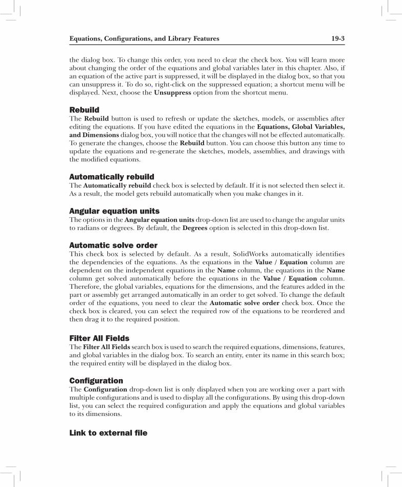
the dialog box. To change this order, you need to clear the check box. You will learn more about changing the order of the equations and global variables later in this chapter. Also, if an equation of the active part is suppressed, it will be displayed in the dialog box, so that you can unsuppress it. To do so, right-click on the suppressed equation; a shortcut menu will be displayed. Next, choose the Unsuppress option from the shortcut menu.
rebuildThe Rebuild button is used to refresh or update the sketches, models, or assemblies after editing the equations. If you have edited the equations in the Equations, Global Variables, and Dimensions dialog box, you will notice that the changes will not be effected automatically. To generate the changes, choose the Rebuild button. You can choose this button any time to update the equations and re-generate the sketches, models, assemblies, and drawings with the modified equations.
automatically rebuildThe Automatically rebuild check box is selected by default. If it is not selected then select it. As a result, the model gets rebuild automatically when you make changes in it.
angular equation unitsThe options in the Angular equation units drop-down list are used to change the angular units to radians or degrees. By default, the Degrees option is selected in this drop-down list.
automatic solve orderThis check box is selected by default. As a result, SolidWorks automatically identifies the dependencies of the equations. As the equations in the Value / Equation column are dependent on the independent equations in the Name column, the equations in the Name column get solved automatically before the equations in the Value / Equation column. Therefore, the global variables, equations for the dimensions, and the features added in the part or assembly get arranged automatically in an order to get solved. To change the default order of the equations, you need to clear the Automatic solve order check box. Once the check box is cleared, you can select the required row of the equations to be reordered and then drag it to the required position.
Filter all FieldsThe Filter All Fields search box is used to search the required equations, dimensions, features, and global variables in the dialog box. To search an entity, enter its name in this search box; the required entity will be displayed in the dialog box.
ConfigurationThe Configuration drop-down list is only displayed when you are working over a part with multiple configurations and is used to display all the configurations. By using this drop-down list, you can select the required configuration and apply the equations and global variables to its dimensions.
Link to external file

19-4 SolidWorks for Designers
The Link to external file check box is used to create link between an external text file containing equations and global variables and the active part. You can also export the applied equations and global variables of the active part to a text file by using this check box.
adding global VariablesIn SolidWorks, you can add global variables by using the Equations, Global Variables, and Dimensions dialog box. To do so, invoke the dialog box and choose the Equation View button, if it is not chosen by default. Next, click on the empty cell of the Global Variables node under the Name column and specify a name for the global variable in it, refer to Figure 19-2. Next, click on the cell corresponding to this cell in the Value / Equation column; a shortcut menu will be displayed preceded by an equal to (=) sign. Also, the name specified for the global variable in the previous cell will be displayed in quotation marks.
Now, you can specify the value for the global variable by using the options available in the shortcut menu or by directly entering the desired value in the edit box . You can also select the dimensions from the drawing area as the value of the global variable. You can perform various mathematical operations using symbols such as plus (+), minus (-) and so on, while specifying the values for the equation and global variable in the respective cell. You can also add a comment to the added global variable in its respective cell under the Comments column.
Figure 19-2 The global variable added in the Equations, Global Variables, and Dimensions dialog box
After adding the global variable, you can use it to relate all the equations of the component with each other. Consider a case of the part, whose sketch is shown in Figure 19-3. Invoke the Equations, Global Variables, and Dimensions dialog box and add a global variable with name Length, by following the procedure discussed earlier, refer to Figure 19-4. Next, click on the corresponding empty cell in the Value / Equation column and then specify the value of the global variable as 200. Now, add a comment to the global variable added in its respective cell under the Comments column, refer to Figure 19-4.
Next, add one more global variable as Width in the dialog box and click on the corresponding empty cell in the Value / Equation column; a shortcut menu will be displayed preceded by an equal to (=) sign. Next, choose Global Variable > Length from the shortcut menu; the Length global variable is highlighted in the Value / Equation column, and a green colored

Equations, Configurations, and Library Features 19-5
check mark is also displayed. Now, press the minus (-) key and enter 50 in this cell. Now, select the check mark; the Width global variable is added in the dialog box, refer to Figure 19-4.
Figure 19-3 Sketch of a part
After adding global variables, you need to add equations to relate them with each other by using the added global variables. To do so, click on the empty cell of Equations node under the Name column and select the dimension with the value 200 from the drawing area; its name is displayed in the selected cell. Also, a shortcut menu is displayed in the corresponding cell of the Value / Equation column preceded by an equal to (=) sign. Next, choose Global Variable > Length from the shortcut menu; the Length global variable will be highlighted in the Value / Equation column, and a green colored check mark is also displayed. Select this check mark; the equation will be added in the dialog box, refer to Figure 19-4.
To add the second equation, click on the empty cell of the Equations node under the Name column and select the dimension with the value 40 from the drawing area; its name will be displayed in the selected cell. Also, a shortcut menu is displayed in the corresponding cell of the Value / Equation column preceded by an equal to (=) sign. Next, choose Global Variable > Length from the shortcut menu; the Length global variable is highlighted in the Value / Equation column, and a green colored check mark is also displayed. Now, press the forward slash ( / ) key and enter 5 in this cell, refer to Figure 19-4. Now, select the check mark; the equation is added in the dialog box. Similarly, add equations to the other dimensions of the sketch, refer to Figure 19-4. Note that, after adding all the equations to the sketch, if you change the value of the Length global variable from 200 to 100, all the dimensions will get changed accordingly.
In this release of SolidWorks, you can create the equations in different dimension units like inches, centimeters, millimeters, and all together. You can also create a length variable in the equations by adding relations to different dimensional values of different unit systems. SolidWorks will automatically solve the relations of the dimensions and display the final value of the dimensions.

19-6 SolidWorks for Designers
Figure 19-4 The global variables added in the Equations, Global Variables, and Dimensions dialog box
suppressing and unsuppressing FeaturesYou can also suppress and unsuppress the features of a part or assembly. To do so, invoke the Equations, Global Variables, and Dimensions dialog box and click on the empty cell of the Features node under the Name column. Next, select the feature to be suppressed/unsuppressed from the FeatureManager Design Tree; the name of the feature will be displayed in the selected cell. Also, a shortcut menu will be displayed under the Value / Equation column. Next, choose Global Variable > Suppressed / Unsuppressed from the shortcut menu; the applied option will be highlighted in the corresponding cell with a green colored check mark. Click on the green colored check mark; the feature gets suppressed/unsuppressed, refer to Figure 19-5. Alternatively, you can use numeric value 0 and 1 to unsuppress and suppress a feature, respectively. To do so, enter the value in the desired cell of the Value / Equation column. You can also change an existing option. To do so, click in the corresponding cell and delete the applied option. Next, apply the desired option.
Figure 19-5 Suppressing and unsuppressing features in the Equations, Global Variables, and Dimensions dialog box

Equations, Configurations, and Library Features 19-7
adding EquationsYou can also add equations to a sketch or a feature. To do so, create a sketch and apply dimensions to it. Next, choose Tools > Equations from the SolidWorks menus; the Equations, Global Variables, and Dimensions dialog box will be displayed. If you add equations in the Part mode, then you need to double-click on the feature or features whose dimensions are to be included in the equation. Next, select a dimension from the drawing area. This dimension is called the driven dimension and it will have to equate with other dimensions. The other dimension that the driven dimension will equate with is known as driving dimension. If you modify the driving dimension, the driven dimensions will also be modified accordingly. To select an equation as a driven equation, click on the empty cell of the Equations node under the Name column and select any dimension from the drawing area; its name will be displayed as a variable in the corresponding cell in the dialog box. Next, select the driving dimension from the drawing area; its name will be displayed in the Value / Equation column with a green colored check mark. Now, add the required mathematical relations and select the check mark; an equation will be added. Also, the solution of the equation will be displayed in the Evaluates to column of the dialog box. You can also add different names, comments and so on to all the equations in the Comments column. Next, choose the OK button to exit the dialog box. You may also need to rebuild the model after adding the equations, if the Automatically rebuilt check box is not selected by default.
If you want to draw a rectangle, as shown in
Figure 19-6 Sketch of the rectangle with dimensions
Figure 19-6, whose width automatically reduces to half of its length when the length is modified, you need to apply equations. To do so, invoke the Equations, Global Variables, and Dimensions dialog box and then click on the empty cell of the Equations node under the Name column. Select the dimension with the value 50 from the drawing area; the name of the dimension gets displayed in the corresponding cell of the Name column in the dialog box. Next, select the dimension with the value 100 from the drawing area. Press the asterisk (*) key and enter 0.5 in the corresponding cell of the Value / Equation column, as shown in Figure 19-7. Next, click on the green colored check mark. The value after solving the equation will be displayed in the Evaluates to column of the dialog box. Next, choose the OK button from this dialog box; the sketch will be regenerated and the dimension value of the width of the rectangle will be modified based on the equation applied to it. Also, the equation symbol will be added to the width of the rectangle.
On adding the equations in the part or in the sketch, the Equations folder is automatically created in the FeatureManager Design Tree, as shown in Figure 19-8. You will learn more about this folder later in this chapter.

19-8 SolidWorks for Designers
Figure 19-7 The Equations, Global Variables, and Dimensions dialog box after adding the equation
noteYou can also invoke the Equations, Global Variables, and Dimensions dialog box from the FeatureManager Design Tree. To do so, right-click on the Equations folder in the FeatureManager Design Tree and select Manage Equations.
Editing EquationsYou can edit the equations added to a design by using the
Figure 19-8 The Equations folder created in the FeatureManager Design Tree
Equations, Global Variables, and Dimensions dialog box. To do so, invoke the dialog box and click in the cell with equations to be edited in the Value / Equation column; the cell will become editable and you can now edit the equation. Once the editing is done, click on the green colored check mark displayed in the cell; the changes made will be reflected in the model in the drawing area. Make sure that Automatically rebuild check box is selected in the dialog box to automatically rebuild the applied equation.
tip. You can also edit the equations from the drawing area. To do so, double-click on the dimension that has equations; the Modify dialog box will be displayed with the equations applied in it. Now, you can modify the equations as per your requirement.
suppressing and unsuppressing EquationsWhile creating a model, you can suppress the equations that are not required at a particular stage. To do so, invoke the Equations, Global Variables, and Dimensions dialog box and choose the Equation View button from the dialog box, if it is not chosen by default. Next, right-click on the equation to be suppressed; a shortcut menu is displayed. Now, choose the Suppress option from the shortcut menu; the selected equation will become invisible. Choose the OK button to exit the dialog box.

Equations, Configurations, and Library Features 19-9
To unsuppress the suppressed equation, you need to select the Ordered View option from the dialog box. Select the equation to be unsuppressed by right-clicking on it. Next, select the Unsuppress option from the shortcut menu displayed; the equation gets unsuppressed. Now, choose the OK button to exit the dialog box.
Deleting EquationsYou can delete an unwanted equation from the dialog box. To do so, invoke the dialog box and right-click on the equation to be deleted; a shortcut menu will be displayed. Select the Delete Equation option from the shortcut menu, the equations will be deleted.
Exporting/importing EquationsIn SolidWorks, you can export the equations created for one entity and share them with other entities. To do so, choose the Export button from the Equations, Global Variables, and Dimensions dialog box and save equations in a text file. Next, open another model and import the equations text file into it by choosing the Import button. However, it is recommended to change the name of the dimension by selecting it and changing its name in the Primary Value rollout. Similar to exporting the equation, you can also import an equation by using the Import button.
Working With ConFigurationsIn SolidWorks, you can create multiple instances of a part or an assembly with ease. For example, if you need to create a bolt and nut of different dimensions, you do not need to create the parts of different dimensions, instead you can create multiple configurations. There are two methods of creating configurations: manually and by using the design table. The method of creating configurations manually is discussed next and the second method will be discussed later in this chapter.
Creating Configurations ManuallyYou can create the configurations manually and specify the properties of these configurations. Then, you can modify the model or the assembly to create variations in the new configuration. Consider the machine bed shown in Figure 19-9. You need to create two types of designs of the same machine bed. In the first design, you need to have a circular pocket on the top face of the machine bed, whereas in the second design, the circular pocket is to be removed from the top face of the machine bed.
To create configurations manually, you need to
Figure 19-9 Model of a machine bed
invoke the ConfigurationManager. To do so, choose the ConfigurationManager button next to the PropertyManager button below the CommandManager. You will observe that the model of the machine bed shown in Figure 19-9 is saved as the Default configuration and is active. The node of the active configuration is shown in yellow color.

19-10 SolidWorks for Designers
To create a new configuration, select the name of the part in the ConfigurationManager and right-click to invoke the shortcut menu. Choose the Add Configuration option from the shortcut menu, as shown in Figure 19-10. On choosing this option from the shortcut menu, the Add Configuration PropertyManager will be displayed, as shown in Figure 19-11. In the Configuration Properties rollout, you can specify the name of the configuration in the Configuration name edit box.
The description of the configuration can be specified in the Description edit box. Select the Use in bill of materials check box to display the information in the BOM that is provided in this rollout. You can use the Comment edit box to specify the comment about the configuration.
The drop-down list in the Bill of Materials Options rollout is used to specify the name of the part that has to be displayed in BOM when the drawing views are generated with the selected configuration.
On expanding the Advanced Options rollout, you will observe that the Suppress new features and mates check box is selected by default. Therefore, the new features and mates added in some other configuration of the same part will be automatically suppressed in this configuration. Select the Use configuration specific color check box to specify a color for the newly created configuration. On selecting this check box, the Color button will be enabled. Invoke the Color dialog box by choosing this button and specify the color for the configuration.
Figure 19-10 Choosing the Add Configuration option from the shortcut menu
Figure 19-11 The Add Configuration PropertyManager

Equations, Configurations, and Library Features 19-11
After adding all information in the Add Configuration
Figure 19-12 New configuration displayed in the ConfigurationManager
PropertyManager, choose the OK button; the new configuration will be created and will activate automatically. The node of the new configuration will b e d i s p l a y e d i n y e l l o w c o l o r i n t h e ConfigurationManager. Figure 19-12 shows the name of the new configuration displayed in the ConfigurationManager.
After creating the configuration, edit the features of the model that are required to be displayed in the newly created configuration. The design requirement for the machine bed is that the circular recess needs to be removed in the second configuration of the machine bed. Therefore, you need to suppress the cut feature that is used to create the circular recess in the machine bed. To do so, invoke the FeatureManager Design Tree and suppress the cut feature. Now, if you want to switch back to the Default configuration, select the Default configuration from the ConfigurationManager and invoke the shortcut menu. Choose the Show Configuration option; the Default configuration will be displayed and you will observe that the circular recess is not suppressed in this configuration. Alternatively, double-click on the Default configuration in the ConfigurationManager to switch back to it. On the other hand, when you invoke the newly created configuration, you will observe that the circular recess is not displayed in the machine bed. Figure 19-13 shows the machine bed with the Default configuration and Figure 19-14 shows the machine bed with the modified design configuration.
Figure 19-13 Machine bed with the Default configuration
Figure 19-14 Machine bed with the modified design configuration
Editing the Features of a Part with Multiple ConfigurationsWhen you edit the features of a part with multiple configurations, the Configurations rollout is displayed in the PropertyManager of the feature to be edited, as shown in Figure 19-15. You can specify the configuration that you need to modify using the options in this rollout. These options are discussed next.

19-12 SolidWorks for Designers
this configuration
Figure 19-15 The Configurations rollout
If you select the This configuration radio button, the modification made in the feature will be applied only to the current configuration. The same feature will not be modified in the remaining configurations.
all configurationsThe All configurations radio button is selected by default. As a result, modification made in a feature will be applied to all configurations of the current part document.
specify configurationsSelect the Specify configurations radio button to apply modification only to the selected configurations. When you select this radio button, configurations in the part document will be listed in the list box. The current configuration is selected by default. Select the configuration in which you want to apply the modification. The All button is used to select all configurations displayed in the list box.
tip. You can also drag and drop the specific configuration from the ConfigurationManager to an assembly or a drawing document. When you place a component with multiple configurations in an assembly document, the name of the current configuration will be displayed along with the name of the part in the FeatureManager Design Tree.
To change the configuration of the components placed in an assembly document, select a component and invoke the shortcut menu. Choose the Component Properties option from the shortcut menu; the Component Properties dialog box will be displayed. Select the required configuration from the Referenced configuration area and choose the OK button.
You can also change the configurations of a part in each drawing view independently. To do so, select the drawing view and choose the Properties option from the shortcut menu; the Drawing View Properties dialog box will be displayed. In this dialog box, you can change the configuration by selecting different options from the Use named configuration drop-down list.
Creating Configurations by using Design tablesSolidWorks menus: Insert > Tables > Design TableToolbar: Tools > Design Table
Sometimes you may need to create a part that is used repeatedly in your design work. Each instance of that part may have the same geometry but different dimensions. You can create a part having different configurations by modifying dimensions manually.
However, it is recommended to create these types of configurations using the Design Table tool. To do so, choose the Design Table button from the Tools toolbar or choose Insert > Tables > Design Table from the SolidWorks menus; the Design Table Property Manager will be displayed, as shown in Figure 19-16.

Equations, Configurations, and Library Features 19-13
The rollouts in the Design Table PropertyManager are discussed next.
Figure 19-16 The Design Table PropertyManager
source rolloutThe Source rollout is used to specify the type and the source for inserting the design table in the part or assembly document. The options in this rollout are discussed next.
BlankThe Blank radio button is used to insert a blank design table. You need to manually enter the parameters in a blank design table.
auto-createThe Auto-create radio button is selected by default when you invoke the Design Table Property Manager. Therefore you can insert a new design table in the part or the assembly document. It will also load all the parameters and their associated values in the design table.
From fileSelect the From file radio button if you need to insert an existing design table. The design tables are created as Microsoft Excel files. To retrieve a saved design table, select this radio button and choose the Browse button provided in this rollout; the Open dialog box will be displayed. Browse and open the file that you need to insert as design table; the name and path of the selected file will be displayed in the display box provided below the radio button. The Link to file check box will be available only when you select the From file radio button. On selecting this check box, any change made in the Microsoft Excel file will reflect in the part model or the assembly, and vice versa.
Edit Control rolloutThe Edit Control rollout is used to specify the settings of bidirectional control on the design table. The options available in this rollout are discussed next.
allow model edits to update the design tableThe Allow model edits to update the design table radio button is selected by default and is used to add a bidirectional relation between the model and the design table. If you select this radio button, the changes made in the model will be updated in the design table automatically.
Block model edits that would update the design tableThe Block model edits that would update the design table radio button is used to block the editing of the parameters of the model that tend to update the design table.

19-14 SolidWorks for Designers
options rolloutThe options in the Options rollout are used to add rows or columns to the design table and warn you before updating the design table. The options in this rollout are discussed next.
new parametersThe New parameters check box is selected by default and is used to automatically add new rows or columns in the design table when new parameters are added in the drawing view.
new configurationsThe New configurations check box is selected by default and is used to automatically add new columns and rows in the design table when a new configuration is added to the model.
Warn when updating design tableThe Warn when updating design table check box is selected by default. As a result, a warning message appears every time the design table updates.
Consider a case in which you need to create a
Figure 19-17 Washer created using the given dimensions
washer of 100 mm outer diameter, 50 mm inner diameter, and 10 mm thickness, as shown in Figure 19-17. Also, you need to create five more washers with different dimensions. As the geometry of the washers is the same and only the dimensions are different, it is recommended to create a single part document of the washer and then create different configurations of the washer using the design table.
After creating the part model, invoke the Design Table PropertyManager. Select the Auto-create radio button and choose the OK button from the Design Table PropertyManager; the design table will be created with the default settings and the tools in the toolbars of SolidWorks window will be replaced by the Microsoft Excel tools. Also, the Creating design table dialog box will be displayed, overlapped by the Dimensions dialog box. Figure 19-18 shows the SolidWorks window after you have chosen the OK button from the Design Table PropertyManager.
Next, press and hold the CTRL key and select all dimensions displayed in the Dimensions dialog box. Choose the OK button; the name of the selected dimensions with the dimensional values of the Default configuration will be displayed in Microsoft Excel sheet in the drawing area, refer to Figure 19-19. Next, you need to specify the name of the second instance to be created for the model and enter dimensions for that instance in the excel sheet. Similarly, specify the names and dimensions of other instances, refer to Figure 19-20.
After specifying the configurations and dimensions in the Microsoft Excel sheet, click anywhere in the drawing area; the SolidWorks message box will be displayed with the names of the configurations generated by design table. Choose the OK button to close it.

Equations, Configurations, and Library Features 19-15
Figure 19-18 SolidWorks window displayed while creating the design table
Figure 19-19 Microsoft Excel sheet after adding features to the design table
Now, you can observe that different configurations are created in the ConfigurationManager and the Default [Part1] configuration is activated, as shown in Figure 19-21. The Microsoft Excel icon displayed before the Design Table node in the ConfigurationManager confirms that the configuration is generated by using the design table. If you need to view any other configuration, select the configuration and invoke the shortcut menu. Choose the Show Configuration option from the shortcut menu. Alternatively, you can double-click on the configuration in the ConfigurationManager.

19-16 SolidWorks for Designers
Figure 19-20 Microsoft Excel sheet after specifying the name of the new instances and adding dimensions to those instances
Figure 19-21 The Configuration Manager with different configurations
noteYou can create only one design table in a part or an assembly document.
Changing the suppression state by using the Design tableYou can change the suppression state of the features
Figure 19-22 Finished plate
of a component by using the design table. This method is of great use in the design department because you can generate different configurations of a part showing the feature to be created after each stage of the manufacturing process. Assume that you are provided with the finished billet stock and you need to manufacture the plate shown in Figure 19-22.
To manufacture the plate from the billet, you first need to perform the pocket milling operation to remove the material from inside the plate. Next, you need to drill the holes inside the pocket as well as on the top face of the plate. After performing all operations, you need to chamfer the top edges of the plate.
To represent all these stages, you need to create different configurations displaying each of these stages of the manufacturing process using the design table. You can also create these configurations manually, but that will be a time-consuming process.
Before creating these types of configurations, you need to change the names of the feature in the FeatureManager Design Tree. To change the name of a feature, select the feature

Equations, Configurations, and Library Features 19-17
and again left-click on it; the name of the feature will be displayed in a text edit box. Enter a new name for the feature. Remember that it is not mandatory to change the names of the features. It is done to avoid confusion. Save the model and then invoke the Design Table PropertyManager. In this PropertyManager, select the Auto-create radio button, and then choose the OK button; the Dimensions dialog box will be displayed. Without selecting any dimension from the Dimensions dialog box, choose the OK button; a excel sheet is displayed only with the name of the design table. Next, double-click on all features displayed in the FeatureManager Design Tree. You will notice that the names of the features will be displayed in the top row and their respective suppression states will be displayed under the names of the features in Microsoft Excel, refer to Figure 19-23.
Figure 19-23 Microsoft Excel sheet after adding features to the design table
Note that the suppression state of all the features is displayed as unsuppressed. Enter Finished Plate as the name of the configuration in the A3 cell. Enter Billet Stock as the name of the second configuration in the A4 cell. Now, specify the suppression state as suppressed in all the features in the design table, except the base feature. Instead of specifying the complete spelling of suppress and unsuppress, you can enter S for suppressed state and U for unsuppressed state. Next, enter Pocket Milling as the name of the third configuration in the A5 cell and suppress all the features except the base feature, pocket, and fillet features. Similarly, create other configurations. Figure 19-24 shows the design table after specifying all configurations and their respective suppression states.
Next, click anywhere in the drawing area and choose OK from the message box displayed to return to the part modeling environment. Figures 19-25 through 19-29 show different configurations of the plate created by changing the suppression state of the feature by using the design table.

19-18 SolidWorks for Designers
Figure 19-24 Design table after specifying all configurations and their respective suppression states
Figure 19-25 Plate shown in the Billet Stock configuration
Figure 19-26 Plate shown in the Pocket Milling configuration
Figure 19-27 Plate shown in the Dia 5 Holes configuration
Figure 19-28 Plate shown in the Dia 6 Holes configuration

Equations, Configurations, and Library Features 19-19
Editing the Design tableYou can also edit a design table created in the part or the assembly document. To do so, expand the Tables node, and then right-click on the Design Table icon from the ConfigurationManager to invoke the shortcut menu. Choose the Edit Table option from the shortcut menu; the Add Rows and Columns dialog box will be displayed. If some configurations or parameters are added to the model after creating the design table, those configurations and parameters will be listed in the Configurations and Parameters areas of the Add Rows and Columns dialog box. You can select the parameters or the configurations displayed in this dialog box to be included in the design table and then choose the OK button from this dialog box; the part modeling environment will be replaced by the Microsoft Excel application environment and the Microsoft Excel sheet will be displayed in the drawing area. Edit the sheet and then click anywhere in the drawing area to return to the part modeling environment of SolidWorks.
Figure 19-29 Plate shown in the Chamfer configuration
You can also edit the properties of the design table by invoking the Design Table PropertyManager. To do so, select the Design Table icon from the ConfigurationManager and invoke the shortcut menu. Choose the Edit Feature option from the shortcut menu; the Design Table PropertyManager will be displayed and now you can edit the properties of the design table.
tip. You can also edit the design table in a separate Microsoft Excel window. To do so, right-click on the Design Table icon from the ConfigurationManager to invoke the shortcut menu. Choose the Edit Table in New Window option from the shortcut menu; a separate Microsoft Excel window will be invoked and the Add Rows and Columns dialog box will be displayed in SolidWorks window. Choose the Cancel button in this dialog box and then edit the excel file. After editing the design table, close the excel file; the design table will be updated in SolidWorks.
You can also save the design table created in the part or the assembly document. To do so, right-click on the design table icon from the ConfigurationManager and invoke the shortcut menu. Choose the Save Table option from the shortcut menu; the Microsoft Excel sheet will be displayed. If you have updated the model after creating the design table, the Add Rows and Columns dialog box will be displayed. Choose the OK button in this dialog box; the Save As dialog box will be displayed. Enter the file name and select the required location to save the design table.

19-20 SolidWorks for Designers
noteIf you change the names of the features in the Design Table, then while editing this table, the SolidWorks message box will be displayed informing you about the invalid feature name. Choose the OK button; the Add Rows and Columns dialog box will be displayed. Next, choose the OK button to exit this dialog box.
Deleting the Design tableYou can also delete the design table if it is not required in a part or assembly document. To do so, select the Design Table icon from the ConfigurationManager and press the DELETE key; the Confirm Delete message box will be displayed. Next, choose the Yes button from the message box to delete the selected design table. Note that even if you delete the design table, the configurations created by using it will not be deleted.
Changing the suppression state of a Component without invoking the Design tableIn the previous section, you learned to change the suppression state of various features of a component using the design table. However, you can also change the suppression state of a feature without invoking the design table.
To change the suppression state of the features, select them from the FeatureManager Design Tree and invoke the shortcut menu. Choose the Configure Feature option from the shortcut menu; the Modify Configurations window will be displayed with the names of selected features along the columns, as shown in Figure 19-30.
Figure 19-30 The Modify Configurations window
Click once in the <Creates a new configuration.> cell, enter a name for the new feature, and click once in any of the cells; a new row with check boxes will be created for the new configuration. Create some more configurations. Next, to suppress a particular feature in a configuration, select the check box of the corresponding feature, as shown in Figure 19-31. You can also change the dimensions of a feature. Note that the dimensions of a feature refer to the dimensions entered in the PropertyManager while creating the feature and not the dimensions
Equations, Configurations, and Library Features 19-21
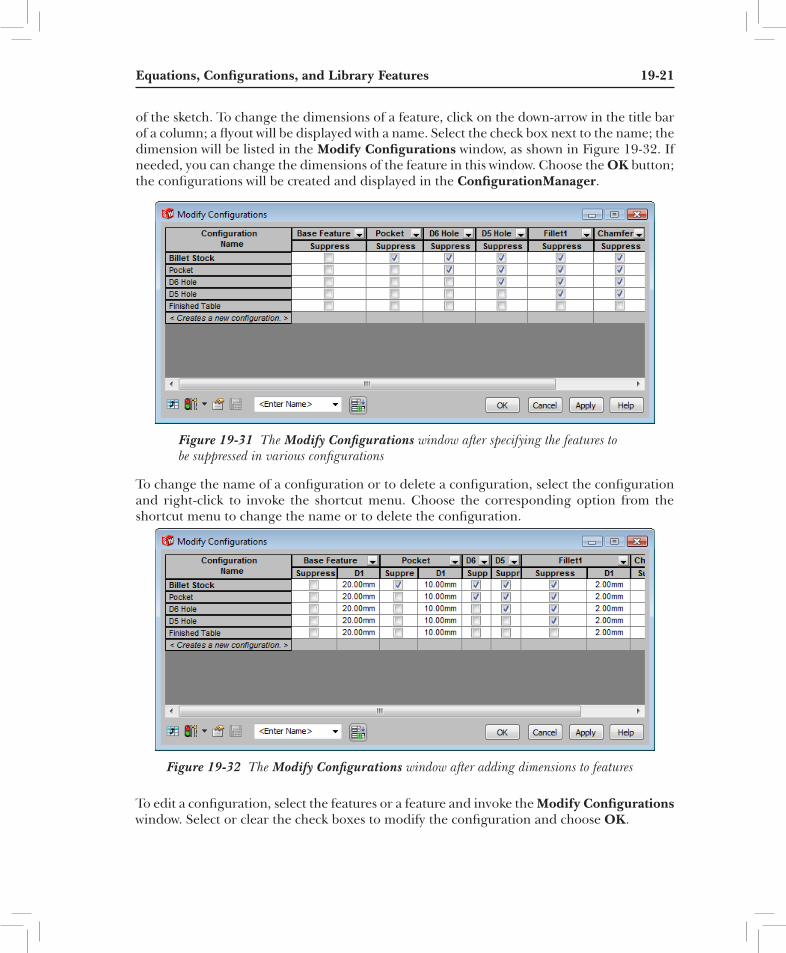
of the sketch. To change the dimensions of a feature, click on the down-arrow in the title bar of a column; a flyout will be displayed with a name. Select the check box next to the name; the dimension will be listed in the Modify Configurations window, as shown in Figure 19-32. If needed, you can change the dimensions of the feature in this window. Choose the OK button; the configurations will be created and displayed in the ConfigurationManager.
Figure 19-31 The Modify Configurations window after specifying the features to be suppressed in various configurations
To change the name of a configuration or to delete a configuration, select the configuration and right-click to invoke the shortcut menu. Choose the corresponding option from the shortcut menu to change the name or to delete the configuration.
Figure 19-32 The Modify Configurations window after adding dimensions to features
To edit a configuration, select the features or a feature and invoke the Modify Configurations window. Select or clear the check boxes to modify the configuration and choose OK.

19-22 SolidWorks for Designers
Changing the Visibility of Components in Different Configurations of an assemblyIn the Assembly mode, you can also change the visibility of components in different configurations. To do so, invoke the ConfigurationManager, and then right-click in the Display States area; a shortcut menu will be displayed. Choose the Add Display State option from the shortcut menu; a new display state will be added. Similarly, you can add as many display states as required. The Display States area after adding more display states is shown in Figure 19-33.To change the color, texture, and display state, double-click on a display state and make it active. Next, invoke the FeatureManager Design Tree and click on the arrow symbol to display the display pane. Now, change the color, display state, or transparency of a part in the assembly. Similarly, make other display states active and change the corresponding color or transparency. Figure 19-34 shows the task pane with color, transparency, and display mode changed for different parts of an assembly.
To view different display states, double-click on the corresponding display state in the Display States area of the ConfigurationManager. Alternatively, invoke the Display States toolbar and select the corresponding display state from the drop-down list.
LiBrary FEaturEsIn most designs, some features are used frequently. In such a case, you can create and save those features as library features so that you can use them in a part, whenever required. This reduces the time to create the same part or feature repeatedly. In this section, you will learn how to create the library feature, place them in a part, edit them, and dissolve them.
Figure 19-33 The display statescreated
Figure 19-34 The FeatureManager Design Tree with the display pane
Creating a Library FeatureA library feature is created by saving an existing feature with different file extension. To save a feature as a library feature, you first need to create a base feature and then the feature or features to be added as the library feature. Next, you need to select the features to be added as the library features and then save them with .sldlfp file extension.

Equations, Configurations, and Library Features 19-23
Consider a case in which you need to save an extruded feature and a fillet feature as the library feature. In this case, first you need to create a base feature. Next, create an extruded feature and add fillets to this feature. After creating the model, select the name of the model from the FeatureManager Design Tree and invoke the shortcut menu. Choose the Add to Library option from the shortcut menu; the Add to Library PropertyManager will be displayed, as shown in Figure 19-35. Also, you will notice that the name of the model is displayed by default in the selection box in the Items to Add rollout. Clear the current selection and select the features to be added as the library feature from the FeatureManager Design Tree. The extruded feature and fillet feature of the model, as shown in Figure 19-36, are selected as library features.
Figure 19-35 The Add to Library PropertyManager
Specify the name for the library feature in the File name edit box of the Save To rollout. Then, select the location to save the library feature by expanding the nodes in the Design Library folder list box.
Select the Lib Feat Part (*.sldlfp) option from the File type drop-down list in the Options rollout, if it is not selected by default. If you want to give a brief description about the feature, specify it in the Description edit box in the Options rollout.
Choose OK after setting all parameters; the features will be saved as the library features. The features that are selected to be saved as library features will have an L symbol displayed on their icons, and the library symbol will be displayed with the name of the part document in the FeatureManager Design Tree, as shown in Figure 19-37.
Invoke the Design Library task pane and browse to the location where you have saved the library feature to view it.
noteIf the library feature is placed with respect to an entity in a feature in which it has been created, then you need to specify the reference while placing the library feature.
Placing Library Features in a PartAfter creating and saving the library features, you can place them in a part document. To place a library feature, invoke the Design Library task pane by choosing the Design Library tab and browse to the location where you have saved the library feature. Then, drag the feature and drop it on a face of the model; the PropertyManager of the corresponding library feature will be displayed, as shown in Figure 19-38. If you need to change the placement plane for the library feature, clear the existing placement plane displayed in the Placement Plane rollout of the Library Feature PropertyManager and select a new placement plane. If the selected library feature has more than one configuration, it will be displayed in the Configuration rollout.

19-24 SolidWorks for Designers
Figure 19-36 The features to be added as library features
Figure 19-37 Library icon and the L symbol displayed on the feature icons
On selecting a library feature created with references, the preview of the feature will be displayed in a window. Also, you will be prompted to specify references. If you click in the preview window, the View (Heads-Up) toolbar will be displayed and you can view the feature by using the tools in this toolbar. Specify the references in the drawing area; the preview window will disappear and the location of the feature with respect to the selected references will be displayed in the Locating Dimensions area of the Library Feature PropertyManager.
If the selected library feature does not have any references, the Location rollout will be displayed. Choose the Edit Sketch button from this rollout and specify the location of the feature.
If you want to modify the existing dimensions of the library feature, select the Override dimension values check box in the Size Dimensions rollout and modify the values. The modified feature will be displayed with the name Custom configuration in the Configuration rollout.

Equations, Configurations, and Library Features 19-25
Figure 19-38 Part document with the Library Feature PropertyManagerIf you select the Link to library part check box in the Configuration rollout, the references of the library feature will be saved in the part. Therefore, if you modify the library feature, the modification will be reflected in the model. Figure 19-39 shows the library feature placed on the top face of the model.
tip. If you include the base feature in a library feature, you can place the library feature only in an empty SolidWorks part document. Instead, if you place it in a part document that already has a base feature, a warning message will be displayed informing you that a library feature with a base feature can be inserted only into an empty part document.
Figure 19-39 Library feature placed on the top face of the model

19-26 SolidWorks for Designers
Editing the Library FeaturesYou can edit or change the features included in the library feature part document. To remove a library feature from the library, select that library feature from the Design Library task pane. Now, invoke the shortcut menu and choose the Delete option from it. If you need to edit the library feature, select the feature from the Design Library task pane. Next, invoke the shortcut menu and then, choose the Open option from it; the part document of the library feature will open. Edit the feature and save it. If you have selected the Link to library part check box in the Configuration rollout while placing the library feature, the modification made in the library feature will reflect in the document in which the library feature is placed.
Dissolving the Library FeaturesWhen a library feature is placed, the library icon will be displayed before the name of the feature. So, if you try to edit the library feature, the Library Feature PropertyManager will be displayed. To convert the library feature into a separate part feature, you need to dissolve the library feature. To do so, select the library feature from the Feature Manager Design Tree and invoke the shortcut menu. Choose the Dissolve Library Feature option from the shortcut menu; the library feature will be dissolved into individual features.
tutoriaLstutorial 1
In this tutorial, you will open the sketch created in Tutorial 3 of Chapter 2, add dimensions to the sketch, as shown in Figure 19-40, and extrude the sketch up to a depth of 50 mm. Then, you will add equations to the dimensions of the sketch. The dimension 150 will be the driving dimension. While adding equations, you can change the vertical dimensions 20 and 40 to 25 and 50, respectively, for the convenience of calculation. (Expected time: 30 min)
Figure 19-40 Sketch for Tutorial 1

Equations, Configurations, and Library Features 19-27
The following steps are required to complete this tutorial:
a. Start a new part document and open Tutorial 3 of Chapter 2.b. Extrude the sketch to a depth of 50 mm.c. Edit dimensions and add equations using the Equations tool.d. Save the model.
starting a new solidWorks Document and Creating an Extrude Feature1. Start a new SolidWorks document and open Tutorial 3 of Chapter 2.
2. Add relations and dimensions to fully define the sketch, refer to Figure 19-40.
3. Extrude the sketch up to a depth of 50 mm.
4. Choose the Save As button and save the model with the name c19_tut01.
adding Equations to the Dimensions in the sketch For this model, you will keep the horizontal dimension 150 as the driving dimension and
other dimensions as the driven dimensions. Also, you will change the vertical dimensions to 25 and 50 mm to ease the calculation.
1. Invoke the sketching environment to edit the sketch of the base feature, double-click on the vertical dimensions in succession, and change the dimension values 20 to 25 and 40 to 50.
2. Choose the Equations button from the Tools toolbar; the Equations, Global Variables, and Dimensions dialog box is displayed.
3. Click on the empty cell of the Global Variables node under the Name column and enter a name Length for the global variable, refer to Figure 19-41. Next, click on the corresponding empty cell in the Value / Equation column and select the dimension with value 150 from the drawing area. Now, add a comment to the global variable added in the respective cell under the Comments column.
4. Now, click on the empty cell of the Equations node under the Name column.
5. Select the radius value 30 from the drawing area; the name of the selected dimension is displayed in the selected cell.
6. Next, select the horizontal dimension value 150 from the drawing area; the name of the selected dimension is displayed in the Value / Equation column with a green colored check mark.
7. Press the forward slash ( / ) key and enter 5; the equation will become “D6@Sketch1” = “D8@Sketch1” / 5, where D6@Sketch1 = 30 and D8@Sketch1 = 150. The names of the

19-28 SolidWorks for Designers
dimensions can be different as they are based on the sequence in which the dimensions are applied to the sketch.
8. Next, click on the corresponding cell in the Comments column; the value 30 mm is displayed in the Evaluates to column and a new empty cell under Equations node will be displayed. Next, you need to enter Radius in the corresponding cell in the Comments column.
Note that you can also use global variables while adding equations.
9. Similarly, click on the empty cell of the Equation node under the Name column and select the diameter value 30 from the drawing area; the name of the selected dimension is displayed in the Name column.
10. Select the horizontal dimension value 150 from the drawing area; the name of the selected dimension is displayed in the Value / Equation column with a green colored check mark.
11. Press the forward slash ( / ) key and enter 5; the equation becomes “D7@Sketch1” = “D8@Sketch1” / 5, where D7@Sketch1 = 30 and D8@Sketch1 = 150.
12. Next, click on the corresponding cell of Comments column; the value 30 mm is displayed in the Evaluates to column. Next, you need to enter Diameter in the corresponding cell of the Comments column.
13. Similarly, add equations to all dimensions given below.
Dimension to be selected Equation to be added Comment
Vertical dimension 25 150/6 Height
50 150/3 Hole Location
35 150/30*7 Slot Location
Horizontal dimension 25 150/6 Slot
5 150/30 Slot depth
14. Resize the Equations, Global Variables, and Dimensions dialog box, if required. The dialog box after adding all equations is shown in Figure 19-41.
15. Choose the OK button from the dialog box; the dimensions are displayed in the sketch environment with the equation symbol ( ). Also, the Equations folder is added to the FeatureManager Design Tree. Next, exit the sketch environment.
adding Equation to the Extrude Feature Next, you need to add equation to the extrude feature such that the equation is controlled
by the horizontal dimension value 150.

Equations, Configurations, and Library Features 19-29
1. Right-click on the Equations folder in the FeatureManager Design Tree; a shortcut menu is displayed. Choose the Manage Equations option from it; the Equations, Global Variables, and Dimensions dialog box is displayed.
Figure 19-41 The Equations, Global Variables, and Dimensions dialog box after adding all equations
2. Double-click on the model in the drawing area; the dimensions of the sketch and feature are displayed.
3. Next, click on the empty cell of the Equations node under the Name column and select the dimension value 50 which is the dimension of the extrude feature.
4. Select the horizontal dimension value 150 in the drawing area. Next, press the forward slash ( / ) and enter 3 in the cell corresponding to this dimension value in the Equation node, refer to Figure 19-42.
Figure 19-42 The Equations, Global Variables, and Dimensions dialog box after adding equations to extrude feature

19-30 SolidWorks for Designers
5. Click and enter Extrude in the corresponding cell of Comments column.
6. Choose the OK button to exit the dialog box.
Changing the Dimensions of the Model1. Click on the model; all dimensions of the model are displayed.
2. Click on the dimensional value 150 and enter 300 in the text box.
3. Rebuild the model; all dimensions of the model are modified.
noteFor convenience, all dimensions have been equated to round figures. However, you can add any mathematical relation to a feature/dimension, but make sure that it does not override the design intent of the model.
4. Save the model.
tutorial 2In this tutorial, you will create the Socket Head Screw shown in Figure 19-43. Assume the base diameter of the screw, d as 30 mm. Add equations to the model, as shown in Figure 19-44. Then, create different configurations by changing the base diameter to 20 mm, 50 mm, 40 mm, and 5 mm and the other related parameters with respect to the relations given in Figure 19-44. (Expected time: 30 min)
Figure 19-44 Parameters of the Socket Head ScrewFigure 19-43 Socket Head Screw

Equations, Configurations, and Library Features 19-31
The following steps are required to complete this tutorial:
a. Create the socket head screw using the Revolved Boss/Base and Extruded Cut tools.b. Create different configurations using the design table.c. Save the model.
Creating the socket head screw1. Start a new SolidWorks document and draw the sketch of the base feature. The base feature
is created by revolving the sketch about 360 degrees. Do not create fillet and chamfer.
2. Dimension the sketch based on the relations given in Figure 19-44. While placing dimensions, you need to change the name of dimensions in the Primary Value rollout of the Dimension PropertyManager. Refer to Figure 19-45 for the names of dimensions.
3. Create the base feature using the Revolved Boss/Base tool.
4. Draw a hexagon on the top face of the base feature and dimension it. Change the name of the dimension, as shown in Figure 19-45.
5. Create the hexagonal cut on the base feature using the Extruded Cut tool.
Figure 19-45 The names of dimensions
6. Add fillets and chamfers to the model.
7. Save the model with the name c19_tut02 in the folder created for Chapter 19.
Creating Configurations using the Design table Next, you need to create the Socket Head Screw of the
same geometry with different dimensions using the Design Table.
1. Choose Insert > Tables > Design Table from the SolidWorks menus; the Design Table PropertyManager is displayed.
2. Select the Auto-create radio button from the Source rollout. Make sure that the Allow model edits to update the design table radio button and all other check boxes in the Design Table PropertyManager are selected.
3. Choose the OK button from the Design Table
PropertyManager; the Dimensions dialog box is displayed.
4. Next, press and hold the CTRL key and select the names of all dimensions, except the D1@Revolve1, D1@Fillet1, D1@Chamfer1, and D2@Chamfer1, from the list box in the Dimensions dialog box. These names correspond to the revolve, fillet, and chamfer features.

19-32 SolidWorks for Designers
5. Choose OK from the Dimensions dialog box;
Figure 19-46 The design table with the default dimensions
the design table with default dimensions is displayed, as shown in Figure 19-46.
6. Enter 20x60, 50x150, 40x120, and 5x15 as the names of the new instances in the A4, A5, A6, and A7 cells, respectively.
noteIf you click in the drawing area by mistake, the design table will disappear. To display it again, invoke the ConfigurationManager, right-click on the Design Table node, and then choose the Edit Table option from the shortcut menu.
7. Enter the dimensions for the new instances with respect to the equations shown in Figure 19-44. The excel sheet after adding the dimensions is shown in Figure 19-47.
Figure 19-47 The new instances and their dimensions
8. In the A3 cell, change the Default name to 30x90.
9. Click anywhere in the drawing area; the SolidWorks message box with the names of the configurations created is displayed.
10. Choose OK in the message box.

Equations, Configurations, and Library Features 19-33
11. Add equations to the fillet and chamfer dimensions using the Equations dialog box, as specified in Figure 19-44.
12. Invoke the ConfigurationManager; the configurations created are listed in it. Double-click on a configuration to make it active.
13. Save the model.
sELF-EVaLuation tEstAnswer the following questions and then compare them to those given at the end of this chapter:
1. You can add mathematical relations between model dimensions or sketch dimensions by using the Equations tool. (T/F)
2. You can edit the equations added to a design by using the Equations, Global Variables, and Dimensions dialog box. (T/F)
3. You can suppress the equations that are not required at a particular stage. (T/F)
4. Configurations help you create multiple instances of a part or an assembly within a single SolidWorks document. (T/F)
5. You can change the suppression state of the features of a component using the design table. (T/F)
6. You cannot suppress the feature of a configuration without using the design table. (T/F)
7. Which of the following PropertyManagers is used to create a design table?
(a) Design Table (b) Create Design Table (c) Physical Dynamics (d) None of these
8. The __________ radio button is selected by default when you invoke the Design Table PropertyManager.
9. To dissolve a library feature, choose the __________ option from the shortcut menu.
10. The features to be added as library features are saved with the __________ file extension.
rEViEW quEstionsAnswer the following questions:
1. If you try to edit a library feature, the Library Feature PropertyManager will be displayed. (T/F)

19-34 SolidWorks for Designers
2. You can place the library feature only in an empty SolidWorks part document after including the base feature into the library feature. (T/F)
3. Which of the following should be invoked to change the color, texture, and display state of a configuration?
(a) Display pane in the FeatureManager (b) Display pane in the PropertyManager (c) Display pane in the ConfigurationManager (d) None of these
4. You can preview a configuration in the ConfigurationManager, even if it has not been opened and saved once. (T/F)
5. You can create only one design table in a part or assembly document. (T/F)
6. You need to suppress an equation to modify the corresponding driven dimension. (T/F)
7. You can invoke the Equations, Global Variables, and Dimensions dialog box by using the Equations node in the FeatureManager Design Tree . (T/F)
8. If the library feature is placed with respect to an entity in the feature in which it has been created, then you need to specify reference while placing the library feature. (T/F)
9. You can also change the visibility of components in different configurations. (T/F)
10. You can drag and drop a specific configuration from the ConfigurationManager to an assembly or a drawing document. (T/F)
ExErCisEsExercise 1
Create the model shown in Figure 19-48. The dimensions of the model are shown in Figure 19-49. Extrude the sketch up to a depth of 20 mm. Then, add equations to the dimensions of the sketch and the feature. The dimension 80 will be the driving dimension. While adding equations, it is suggested to change the dimensions 30 and 15 to 40 and 20, respectively, for the convenience of calculation. (Expected time: 30 min)

Equations, Configurations, and Library Features 19-35
Figure 19-49 Dimensions of the modelFigure 19-48 Solid model for Exercise 1
Exercise 2Draw the sketch of the model shown in Figure 19-50. The sketch to be drawn is shown in Figure 19-51. Extrude the sketch up to a depth of 20 mm. Then, add equations to the dimensions of the sketch and the feature. (Expected time: 30 min)
Figure 19-51 Sketch for Exercise 2Figure 19-50 Solid model for Exercise 2
Exercise 3Create the Cheese Head Screw shown in Figure 19-52. Assume the base diameter of the screw, d as 25 mm. Create the model by using the relations shown in Figure 19-53. Then, create different configurations by changing the base diameter to 20 mm, 15 mm, 12 mm, and 6 mm. Create the other related parameters with respect to the relations given in Figure 19-53. (Expected time: 30 min)

19-36 SolidWorks for Designers
Figure 19-52 The Cheese Head Screw Figure 19-53 Parameters of the Cheese Head Screw
answers to self-Evaluation test1. T, 2. T, 3. T, 4. T, 5. T, 6. F, 7. a, 8. Auto-create, 9. Dissolve Library Feature, 10. .sldlfp


