C u rren t S t at u s on J oi n t L7 5 E n g i n e Dev el ...
10
See discussions, stats, and author profiles for this publication at: https://www.researchgate.net/publication/325595258 Current Status on Joint L75 Engine Development with Focus on Turbopump Activities Conference Paper · May 2018 CITATIONS 0 READS 191 10 authors, including: Some of the authors of this publication are also working on these related projects: Experimental and Numerical Investigations of the Flow Field in a Generic Planar Expansion-Deflection Nozzle View project L75 Liquid Propellant Rocket Engine View project Lysan Pfützenreuter German Aerospace Center (DLR) 5 PUBLICATIONS 2 CITATIONS SEE PROFILE Daniel Soares De Almeida Instituto de Aeronáutica e Espaço 40 PUBLICATIONS 81 CITATIONS SEE PROFILE Cristiane Maria de Moraes Pagliuco Instituto de Aeronáutica e Espaço 8 PUBLICATIONS 17 CITATIONS SEE PROFILE Holger Burkhardt German Aerospace Center (DLR) 30 PUBLICATIONS 179 CITATIONS SEE PROFILE All content following this page was uploaded by Lysan Pfützenreuter on 06 June 2018. The user has requested enhancement of the downloaded file.
Transcript of C u rren t S t at u s on J oi n t L7 5 E n g i n e Dev el ...

See discussions, stats, and author profiles for this publication at: https://www.researchgate.net/publication/325595258
Current Status on Joint L75 Engine Development with Focus on Turbopump
Activities
Conference Paper · May 2018
CITATIONS
0
READS
191
10 authors, including:
Some of the authors of this publication are also working on these related projects:
Experimental and Numerical Investigations of the Flow Field in a Generic Planar Expansion-Deflection Nozzle View project
L75 Liquid Propellant Rocket Engine View project
Lysan Pfützenreuter
German Aerospace Center (DLR)
5 PUBLICATIONS 2 CITATIONS
SEE PROFILE
Daniel Soares De Almeida
Instituto de Aeronáutica e Espaço
40 PUBLICATIONS 81 CITATIONS
SEE PROFILE
Cristiane Maria de Moraes Pagliuco
Instituto de Aeronáutica e Espaço
8 PUBLICATIONS 17 CITATIONS
SEE PROFILE
Holger Burkhardt
German Aerospace Center (DLR)
30 PUBLICATIONS 179 CITATIONS
SEE PROFILE
All content following this page was uploaded by Lysan Pfützenreuter on 06 June 2018.
The user has requested enhancement of the downloaded file.
1
SP2018-00287
Current Status on Joint L75 Engine Development with Focus on Turbopump Activities
Lysan Pfützenreuter(1), Holger Burkhardt(1), Bernd Wagner(2), Daniel S. Almeida(3), Cristiane M.M.
Pagliuco(3), Leonardo B. Nascimento(3), Bernardo R. D. Souza(3), Ekaterina S. Zink(3), Ronaldo Chaves Reis(3), Jan Alting(4), Chris Maeding(4), and Günter Langel(5)
(1) DLR, German Aerospace Center, Koenigswinterer Str. 522-524, 53227 Bonn, Germany
(2) DLR, German Aerospace Center, Institute of Space Propulsion, Lampoldshausen, 74239 Hardthausen, Germany
(3) IAE, Institute of Aeronautics and Space, P. Mal. Eduardo Gomes, 50, 12228-904, São Jose dos Campos, SP, Brazil.
(4) ArianeGroup GmbH, Robert-Koch-Str.1; 82024 Taufkirchen, (5) Consultant, 81827 Munich, Germany
KEYWORDS: space propulsion, green propulsion, turbopump, combustion chamber, development status ABSTRACT: Since 2011, Brazil and Germany have been cooperating in the development of the L75 engine. First, IAE has been focusing on the design, manufacturing, and testing of subsystems while DLR provided engineering support for the review of the design, the specifications, and the development plans. Furthermore, both parties successfully performed a joint hot firing test campaign of the capacitive thrust chamber in 2016. Since then, the focus of joint activities has been on turbopump developments. An overview of Brazilian pumps and turbine test facility and the plans for the German test hardware will be the main foci of this paper next to an update of the general programmatic framework and status.
1. INTRODUCTION
The L75 project aims to develop a liquid propulsion rocket engine (LPRE) powered by the propellant combination liquid oxygen (LOx) and ethanol and delivering a vacuum thrust of 75 kN. The development started in 2008 in Brazil. In 2011, the Brazilian Space Agency AEB and Germany’s Space Administration DLR decided to extent the more than 30 years of successful Brazilian-German space cooperation with so far strong focus on sounding rockets to the field of liquid propulsion.
Within the first project phase, work was focused on system studies and the design of the engine’s main assemblies thrust chamber (TCA) and turbopump (TPA). System studies basically covered engine cycle analysis and freeze of the engine technical specification. For the TCA, component design and
manufacturing were performed culminating in successful testing of a full-scale pre-development model (PDM). Tests have been performed at DLR’s test facility in Lampoldshausen/Germany. Two different injector heads were tested proving stable combustion in transient and steady state conditions ([1], [2], [3]).
In parallel to the TCA development, TPA activities have been focused on the design, manufacturing, and testing of a PDM of the TPA components LOx pump, fuel pump, and turbine in Brazil using model fluids as water and gaseous nitrogen. Those tests provided inputs for the first TPA development model. In the past, Germany supported the Brazilian design work substantially with engineering activities like mechanical and thermal design, CFD analysis, and technical reviews. Additionally, Germany participated in the project with support in the field of seals and bearings and design, manufacturing, testing of various configurations for TPA inducers.
Today’s activities in Germany concentrate on design and manufacturing of German designed TPA demonstration components, as an alternative solution for the TPA of the L75 engine. The plan is to test them in Brazil within the next two years. 2. L75 ENGINE
The L75 is an open cycle engine using the Gas Generator (GG) principle fed with the propellant combination LOx/ethanol. The engine shall develop a thrust of 75 kN and is designed for an upper stage application for satellite launchers operating for approximately 400 seconds. Table 1 summarizes the required characteristics of the L75 engine and the GG.
The propellant feeding to the combustion chamber is performed by a turbomachinery. The pumps are driven by a turbine which is fed

2
by the exhaust gases of the GG. The turbomachinery is of a single shaft overhang design. Combustion chamber and GG ignitions, as well as turbomachinery start-up, are provided by pyrotechnical devices.
Table 1: L75 engine and GG characteristics
Parameter ValueThrust in vacuum [kN] 75.0Specific impulse in vacuum[s] 315TC LOx flow [kg/s] 14.10TC ethanol flow [kg/s] 8.85Chamber pressure [MPa] 5.85Nozzle area ratio [-] 147GG pressure [MPa] 4.82GG LOx flow [kg/s] 0.31GG ethanol flow [kg/s] 1.0
The TCA design consists of a regeneratively cooled combustion chamber with a copper alloy liner and a stainless steel outer shell. The injector head contains 91 double swirl injection elements.
The nozzle extension is made of two differently designed sections. The upper section is regeneratively while the rear part is radiation cooled. Engine regulation e.g. valve switching is provided by a control unit arranged in a separate box. A thrust frame is mounted around the engine to carry the loads.
For characterization of engine stability characteristics and gaining preliminary information on c*- performance and injector resistance behavior three predevelopment short chamber models - capacitively cooled -have been manufactured. After hardware acceptance including injector flow checks with water at IAE in Brazil the hardware was shipped to Lampoldshausen, Germany for hot testing at DLR’s P8 facility [1], [5] (Figure 1). In parallel, subscale injector and chamber models were manufactured for e.g. injector element optimization. These models will be tested at IAE’s facility in São José dos Campos in late 2018.
Figure 1: CTC PDM Hot Firing Test
3. ACHIEVEMENTS
The work during the first phase lasting from 2011 to 2016 has been mainly focused on the consolidation of the engine’s development plan, the definition of technical and functional requirements for subsystems, manufacturing demonstration as well as definition, layout, and realization of test facilities. The first phase was accomplished by design, manufacturing, and tests of first predevelopment hardware for combustion chamber and injector, gas generator, ignition systems and turbopump starter, as well as for turbopump components – inducer, impeller, LOx and fuel pump, and turbine.
3.1. Engine System
Following a first joint review of the L75 engine, the development plan was updated and the operational concept was modified. The engine components design was supported by use of existing databases from previous developments [1]. In the following the activities for some engine components are discussed.
Combustion Devices:
Design and layout was performed for the gas generator and combustion chamber. Three models of each component were manufactured and tested. The gas generator tests were executed at IAE’s test facility in São José dos Campos, Brazil [4], while combustion chamber testing was done at DLR’ s P8 test facility in Lampoldshausen, Germany. For further investigation and to improve the injector concept subscale injector and chamber models were designed and manufactured. The subscale chamber is a scaled model of the L75 thrust chamber with a reduced number of injection elements and with a smaller nozzle area ratio. In 2018, hot tests at ambient conditions are foreseen to be done in São José dos Campos. Figure 1 and 2 present pictures of combustion devices hardware and hot runs.
Furthermore, hot tests of the GG at the Brazilian 20 kN test stand are continuing, including hot tests with a distributor and a turbine nozzle cascade assembly. The later ones aim to evaluate the efficiency of the GG and the a homogeneous flow along the entire course of hot gases from GG to the turbine disk front, and also nozzle cascade characteristics, such as expansion ratio and efficiency.

3
Figure 2: Gas Generator development model on the left and a thermal image taken during a hot test on
the right.
Ignition and Turbopump Start System:
Substantial engineering effort was spent on the design choice for the combustion chamber and gas generator ignition as well as for the turbopump start system.
For the selection of a suitable solution for chamber and gas generator ignition system, a trade off study was performed treating, comparing, and evaluating various design options. Finally, a pyrotechnical ignition system turned out to be the best solution not only because of available heritage at IAE. After the design phase, development models for all three applications were manufactured and tested successfully at IAE’s test bench in São José dos Campos. Figure 3 shows a photo of an igniter hot test.
Figure 3: Hot test of igniter
Engine Control:
In Phase 1, some investigations were performed dealing with engine control and regulation issues. The effort done in that important field is oriented on the today’s engine design status. The work concentrated mainly on trade offs and discussion of design options for valves and regulation devices. In
the next phase, the effort in that engineering field has to be enhanced.
3.2. Test Facilities
TPA Test Facility:
To be able to test turbopump components with simulation fluids, the available concept and design for the installation of a test facility named BTBH was realized at IAE’s plant in São José dos Campos. Facility operation started in 2014 with acceptance testing and mid 2015 the facility was declared ready for development testing. Up to now, a series of test campaigns were successfully accomplished for all turbopump components. Figure 4 shows a picture of the test facility.
Figure 4: Hydraulic Pumps and Turbine Test Stand (BTBH)
The BTBH was designed to carry out the tests of pumps and turbine of the L75 engine. This test stand is able to measure the parameters of the water flow and gaseous nitrogen flow within the test envelope defined in the pumps or turbine test specifications, respectively. In this way, the procedures developed must ensure that the tests are performed under the conditions and with the assemblies requested in these specifications. To obtain performance and cavitation parameters for pumps, water is used as the model fluid and therefore, similarity relations must be used to obtain the expected values with the actual fluid.
The BTBH was designed to have three configurations, the first one using the water circuit for tests of the oxidant and fuel pumps with water as a model fluid, the second using the circuit of gaseous nitrogen for the cold tests of the turbine, and the third configuration using the cryogenic circuit for tests of the oxidant pump using as model fluid liquid nitrogen. Figure 5 shows the BTBH water supply line, Figure 6 shows the gaseous nitrogen feedline, and Figure 7 shows the cryogenic circuit.

4
Figure 5: BTBH water supply line for pump tests
Figure 6: BTBH gaseous nitrogen feedline for turbine tests
Figure 7: BTBH cryogenic circuit for LOx pump tests
Figure 8: 20 kN Test Stand
TCA Test Facility:
Two facilities exist for combustion device testing. The 20 kN test facility is located in São José dos Campos. Figure 8 shows a photo of the IAE facility. The facility can manage to handle pressure levels and mass flows compatible with the requirements needed to verify the design of the gas generator and combustion chamber subscale models.
All hot firings on full scale level have been performed at DLR’s technology facility P8 ([6], [7], and [8]). The P8 facility is well equipped for operating predevelopment hardware with cryogenic and gaseous propellants. For operation of the L75 combustion chamber models a new Ethanol supply line had to be installed in the P8 facility. The facility was ready for test mid-2016. Figure 9 shows a photo of the DLR’s P8 facility before the ethanol facility upgrade.
Figure 9: P8 Test Bench at DLR Lampoldshausen
Engine and Subassembly Test Facility:
It is obvious that IAE needs adequate test facilities for the development, qualification, and acceptance testing of the L 75 engine system. The test facility needs to cover engine system tests as well as options to test the main assemblies thrust chamber and turbo machinery. That means that one test cell has to be equipped with high pressure operation installations. Figure 10 shows a layout of the LPRE facility. German industry supported the activities through requirement discussions, reviews, and layout ideas. The realization of the facility is planned to be done within the next phase of the L75 development.
Today’s layout of the P8 test facilities does not allow tests of the complete L75 engine or its power pack due to the lack of a suitable low pressure propellant supply. However, the P8 is currently being enlarged by a third test cell -the P8.3 - which is designed to be able to accommodate an ethanol supply and to test the power pack and/or the engine within a reduced operational envelope.

5
Figure 10: Engine test stand preliminary configuration
4. L75 TURBOMASCHINERY
4.1. Turbopump Assembly Concept
In an LPRE development, the TPA bears primary importance because of its long and challenging development cycle in all phases of engine construction: design, development, and fabrication. The TPA is a highly loaded engine component with a large number of interrelated design elements.
The TPA belongs to the feed system of the L75 Engine and it provides the required pressures and flow rate into the thrust and gas generator combustion chambers. The TPA is constituted of the following main components: oxidizer pump, fuel pump, turbine, housing, and seals and bearings unit.
Considering cavitation characteristics and fuel rich gas on turbine side, the oxidizer pump is located at one end of the shaft and the fuel pump in the middle. The system analyses of the gas generator cycle lead to the turbine configuration. A single axial-flow partial admission supersonic stage impulse type turbine is used. It drives the pumps by a single shaft transmission. Nevertheless, the shaft is supported by four angular-contact ball-bearings disposed in pairs in a back-to-back configuration. The bearings at both positions work with ethanol for cooling and lubrication purpose. In this way, the design, test, and qualification efforts are reduced.
Between the two pumps, an inter-propellant seal is foreseen to avoid any interaction between propellants. Figure 11 shows a rendered CAD cut-off view of the overall L75 TPA design.
Figure 11: TPA Configuration
The main design parameters of the TPA are summarized in Table 2.
Table 2: L75 TPA Characteristics
Component Value
Pu
mp
s LOx mass flow [kg/s] 14.4 LOx pressure rise [MPa] 7.2 Fuel mass flow [kg/s] 9.8 Fuel pressure rise [MPa] 10.4
Tu
rbin
e Gas inlet temperature [K] 900 Mass flow [kg/s] 1.3 Pressure ratio [-] 14.2 Power [kW] 400
Rotational speed [rpm] 24,000
4.2 Accomplished Activities
In the frame of the Brazilian-German cooperation on the development of the L75 liquid propellant engine, a more in-depth cooperation was agreed covering selected turbopump topics. As a result of this, an exchange of knowledge and experience, which is beneficial for both the German and the Brazilian partners, has since been established.
On one hand, the TiR (Turbopumps in Rocket engines) group of the DLR Institute of Space Propulsion in Lampoldshausen contributes with its experience and its established network to industrial and academic partners in the field of turbopumps. Furthermore, contact to key supplier of critical subcomponents e.g. seals and bearings in Germany, is managed by DLR Institute of Space Propulsion.
On the other hand, IAE provides detailed design solutions and drawings of components and they are responsible for the hardware integration. During the first phase of the L75 project the following activities were carried out by IAE.
The hydraulic and aerodynamic design of all components was completed, so that first development models could be manufactured. A manufacturing demonstrator of the TPA is

6
shown in Figure 12. The LOx pump was the second part, which was tested with water at BTBH. During the tests, the pump performance was measured and compared to the prediction. The data was also used to update the L75 engine mathematical model with more precise values. Pump cavitation tests followed. By lowering the inlet pressure, the pump behavior under cavitation condition was investigated. The predevelopment model of the LOx pump in test configuration mounted at the BTBH is shown in Figure 13.
Figure 12: Turbopump manufacturing demonstrator
Figure 13: LOx pump development model installed in the test stand.
Within the cooperation, CFD (Computational Fluid Dynamics) analysis of the LOx pump has been performed using commercial tools prior to testing. ArianeGroup GmbH simulated the pump also in water on dedicated load points. The simulation model including its boundary conditions are depicted in Figure 14.
Parallel to the BTBH pump testing, an inducer has been characterized in water at TU Kaiserslautern, Germany [9] with hardware provided by DLR Lampoldshausen.
Figure 14: CFD simulation model of the LOx pump including the applied boundary conditions (mdot:
mass flow, RPM: rotational speed, ptot: total pressure, T: temperature). The shroud is not shown
for clarity.
The head and efficiency characteristics have been evaluated for two different inlet pressures at design speed of the LOx pump. In addition, the suction performance has been measured by the typical head drop and flow visualization. The gained results are used for cross checks and validation work.
The pump test activities have been followed by testing a first turbine predevelopment model. Of course, the BTBH has been modified for these tests. The dedicated turbine test hardware mounted at the test bench is shown in Figure 15.
The test approach during the cold tests of the turbine at BTBH is to use the full-scale turbine and run it with nitrogen as model fluid. Similarity rules are used to determine in which test conditions the turbine shall run in order to obtain data that is relevant to the operation with the GG.
Figure 15: Turbine predevelopment model installed in the test stand
The detailed test procedure and results can be found in [10].
7
Based on the L75 turbopump design, alternative manufacturing methods have been investigated for the LOx-impeller on DLR side, including novel additive manufacturing approaches. However, three different impellers adapted from the IAE baseline design were investigated in terms of their manufacturing precision. High speed spin tests were performed to evaluate the structural integrity of these parts. All tested hardware passed successfully the spin tests [11].
A secondment of DLR scientific staff to IAE, at the end of the first project phase underlined the joined efforts on turbopump development.
Two turbo pump long lead items from the first project phase are still under consideration: The seals and bearings for the flight turbo pump hardware.
The preliminary design study for the inter-propellant seal and the seal between the ethanol pump and the turbine is about to be finalized. The overall functionality and the detailed leakage estimation were in the foci of this study. Depending on the sub-seal system, different approaches like numerical fluid structure interaction and empirical scaling were used by the contracted company. The available seals fulfill the requirements.
Bearings have been designed for the flight hardware corresponding to the requirements and the expected radial and axial loads. For future experimental investigations of cooling behavior of ethanol, angular contact ball bearings are adapted for different pretensions. The test under realistic boundary conditions will help to improve the bearing design and to optimize the bearing coolant mass flow. A small batch of bearings is in production and will be ready for testing middle of 2018.
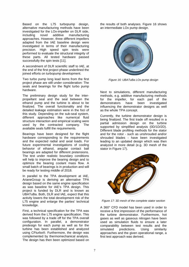
In parallel to the TPA development at IAE, ArianeGroup is deriving an alternative TPA design based on the same engine specification as was baseline for IAE’s TPA design. This project is funded by DLR and is known as UBATuBa. Both, DLR and IAE, expect that this activity lowers the total development risk of the L75 engine and enlarge the parties’ technical knowledge.
First, a technical specification for the TPA was derived from the L75 engine specification. This was followed by a trade off for the TPA overall configuration. In parallel, a demonstrator predesign for each pump as well as for the turbine has been established and analyzed using CFturbo®. Furthermore, the design was complemented by thermomechanical analysis. The design has then been optimized based on
the results of both analyses. Figure 16 shows an intermediate LOx pump design.
Figure 16: UBATuBa LOx pump design
Next to simulations, different manufacturing methods, e.g. additive manufacturing methods for the impeller, for each part of the demonstrators have been investigated influencing the demonstrator designs as well as the whole TPA concept.
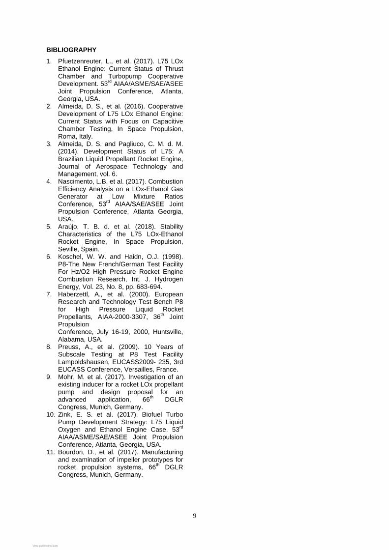
Currently, the turbine demonstrator design is being finalized. The first trade off resulted in a partial admission design on the turbine supported by simplified analysis (0D/1D/2D). Different blade profiling methods for the stator and for the rotor - such as unshrouded and/or shrouded blades - have been investigated leading to an updated design which was then analyzed in more detail (e.g. 3D mesh of the stator in Figure 17).
Figure 17: 3D mesh of the complete stator section
A 360° CFD model has been used in order to receive a first impression of the performance of the turbine demonstrator. Furthermore, hot gases as well as gaseous nitrogen have been used as simulation fluids to ensure a later comparability between test results and the simulated predictions. Using similarity approaches and the given operational range, a first test approach was derived.

8
4.3. Future Work
Currently, the scope of the next phase of the L75 development is still under discussion in Brazil. Nevertheless, regarding the TPA development it is absolutely necessary to review and iterate the current design of the components based on the component testing. Furthermore, a complete TPA predevelopment model has to be designed, manufactured, and tested.
The main activities from German side will be focusing on the finalization of the running activities related to the demonstrator design and manufacturing. The turbine demonstrator will be manufactured mid of 2018 and will be sent to Brazil for testing at the BTBH by the end of this year. The LOx pump and the ethanol pump will follow next year. The tests will be performed by Brazilian staff supported by German test engineers. Results of the test campaigns of all demonstrator components might be used for further design optimization by both partners.
5. CONCLUSIONS & OUTLOOK
This paper presents the status of the cooperation of DLR and IAE for the development of the L75 engine concentrating on the TPA activities.
In Brazil, the BTBH was designed, erected, and successfully put into operation in the last years. IAE - supported by industry as well as research institutes on both sides of the Atlantic Ocean - designed, manufactured, and tested predevelopment models of the TPA components (LOx pump, ethanol pump, and turbine).
In addition, ArianeGroup also designed these TPA components based on the same engine specification but with absolute freedom of design. These demonstrators are currently manufactured and will use the existing infrastructure in Brazil for testing. Both parties will benefit from the knowledge increase.
The activities and results achieved within the last years of Brazilian/German cooperation have proven that the team is capable to design and qualify a liquid rocket engine. The combination of heritage on both sides turned out to be beneficial providing an efficient and cost-effective approach. Facilities on both sides of the Atlantic Ocean are and will be used in order to make best use of available installations.
Next to TPA development, the main activities to be carried out in the next phase of the L75 project development in Brazil will be:
manufacturing and testing of the engineering models of the L75 engine components,
integration of an entire development model of the L75 engine,
critical review of the L75 engine components, and
construction of the engine test stand (Figure 10).
The development of the L75 engine requires a number of enabler products, among which are the test stands. These test stands are required for the development and qualification of the subsystems and engine components at various levels, such as: injectors, valves, pumps, turbine, gas generator, turbopump, thrust chamber, and complete engine.
The largest test stand in Brazil for liquid propellant rocket engines is at IAE, São José dos Campos, and has capacity to test engines up to 20 kN, using LOx and ethanol as propellants. This test stand has been and will be used in the L75 Engine GG development.
The DLR test bench P8 – including its extension of a third test cell - could be used for further TCA and power pack tests with reduced operational envelope.
Even though, for the next phase of L75 development there are discussions ongoing in Brazil to invest into a dedicated own test stand. This facility would assure the development tests of the TCA, the power pack, and the whole engine which might be beneficial compared to the contracting abroad of all the necessary campaigns for the mentioned components up to the qualifying stage.
However, the combination of development activities by bilateral cooperation is an appropriate measure to fulfill challenging tasks. Next steps will include system and subsystem design, subsystem testing as well as launcher system engineering tasks. Discussions on cooperating on those topics are still ongoing.
ACKNOWLEDGEMENTS
The German activities are supported by DLR with funds of the German Federal Ministry for Economic Affairs and Energy (references: 50 RL 1411 and 50 RL 1610).
IAE thanks the Brazilian Space Agency AEB for funding the L75 project and the support received from the National Counsel of Technological and Scientific Development - CNPq (Process 400938/2014-6).
9
BIBLIOGRAPHY
1. Pfuetzenreuter, L., et al. (2017). L75 LOx Ethanol Engine: Current Status of Thrust Chamber and Turbopump Cooperative Development. 53rd AIAA/ASME/SAE/ASEE Joint Propulsion Conference, Atlanta, Georgia, USA.
2. Almeida, D. S., et al. (2016). Cooperative Development of L75 LOx Ethanol Engine: Current Status with Focus on Capacitive Chamber Testing, In Space Propulsion, Roma, Italy.
3. Almeida, D. S. and Pagliuco, C. M. d. M. (2014). Development Status of L75: A Brazilian Liquid Propellant Rocket Engine, Journal of Aerospace Technology and Management, vol. 6.
4. Nascimento, L.B. et al. (2017). Combustion Efficiency Analysis on a LOx-Ethanol Gas Generator at Low Mixture Ratios Conference, 53rd AIAA/SAE/ASEE Joint Propulsion Conference, Atlanta Georgia, USA.
5. Araújo, T. B. d. et al. (2018). Stability Characteristics of the L75 LOx-Ethanol Rocket Engine, In Space Propulsion, Seville, Spain.
6. Koschel, W. W. and Haidn, O.J. (1998). P8-The New French/German Test Facility For Hz/O2 High Pressure Rocket Engine Combustion Research, Int. J. Hydrogen Energy, Vol. 23, No. 8, pp. 683-694.
7. Haberzettl, A., et al. (2000). European Research and Technology Test Bench P8 for High Pressure Liquid Rocket Propellants, AIAA-2000-3307, 36th Joint Propulsion Conference, July 16-19, 2000, Huntsville, Alabama, USA.
8. Preuss, A., et al. (2009). 10 Years of Subscale Testing at P8 Test Facility Lampoldshausen, EUCASS2009- 235, 3rd EUCASS Conference, Versailles, France.
9. Mohr, M. et al. (2017). Investigation of an existing inducer for a rocket LOx propellant pump and design proposal for an advanced application, 66th DGLR Congress, Munich, Germany.
10. Zink, E. S. et al. (2017). Biofuel Turbo Pump Development Strategy: L75 Liquid Oxygen and Ethanol Engine Case, 53rd AIAA/ASME/SAE/ASEE Joint Propulsion Conference, Atlanta, Georgia, USA.
11. Bourdon, D., et al. (2017). Manufacturing and examination of impeller prototypes for rocket propulsion systems, 66th DGLR Congress, Munich, Germany.
View publication statsView publication stats