C-Through: Part-time Optics in Data Centers Guohui Wang*, David G. Andersen†, Michael Kaminsky‡,...
32
c-Through: Part-time Optics in Data Centers Guohui Wang*, David G. Andersen†, Michael Kaminsky‡, Konstantina Papagiannaki‡, T. S. Eugene Ng*, Michael Kozuch‡, Michael Ryan‡ ?Rice University, †Carnegie Mellon University, ‡Intel Labs Pittsburgh
-
Upload
tyler-preston -
Category
Documents
-
view
215 -
download
2
Transcript of C-Through: Part-time Optics in Data Centers Guohui Wang*, David G. Andersen†, Michael Kaminsky‡,...

c-Through: Part-time Optics in Data Centers
Guohui Wang*, David G. Andersen†, Michael Kaminsky‡, Konstantina Papagiannaki‡,T. S. Eugene Ng*, Michael Kozuch‡, Michael Ryan‡
?Rice University, †Carnegie Mellon University, ‡Intel Labs Pittsburgh

概要• How to achieve high throughput among
remote servers in a data center• Hybrid packet and optical circuit switched data
center network architecture (HyPaC)• Core switching architecture resides in end
hosts (see-through -> c-through)

背景• Emerging applications which require to handle large
amounts of data– VM migration– Data mining ex. Hadoop
• Oversubscription problem– Increasing number of servers interconnected via switch– Ex. 1000hosts with 10Gb/s link = Oversubscription ratio of 1000
• Necessity for higher throughput among remote servers within a datacenter
• Optical circuit switching technology– Higher bandwidth / slower switching speed

Optical Circuit Switching• Technologies
– MEMS-based Optical Circuit Switch• Does not encode/decode packets• No requirement for tranceivers
– Wavelength Division Multiplexing (WDM)• larger transmission rate
• Characteristics– Pros
• 40Gb/s ~ 100Gb throughput (40Gb/s < on electrical ether)
– Cons• 20ms to switch to a new I/O port
– reconfiguration time of mirror rotation

HyPaC network Architecture
• ToR switches are electrically/optically connected
• Each rack can have at most one high bandwidth(optical) connection at a time
• Design Choices– Traffic Demand Estimation
• Performed@end host(servers) ; Increases the per-connection socket buffer size, and observe end-host buffer occupancy at runtime
• Provides HOL
– Traffic Demultiplexing• Partition electrical & optical network in 2 logical network
using VLAN
– Circuit Utilization Optimizing• Buffer additional data in TCP socket buffers, rely on TCP’s
functionality to burst send data

Design and ImplementationManaging Optical Paths
• Traffic Measurement– Increases the per-socket TCP socket buffer on
runtime– Buffering at end hosts– each server computes for each destination rack the
total numbers of bytes waiting in socket buffers, and reports these per-destination-rack demands to the optical manager
– Easy to scale (DRAM cheaper on end hosts than ToR switches)
• Utilization Optimization– Modifying the size of per-socket buffer
• Optical Configuration manager– collects traffic measurements from end-nodes, and
determines how optical paths should be configured, issues configuration directives to the switches and informs hosts which paths are optically connected
– small central manager attached to the optical switch (similar to a router control plane)
– tries to maximizes the amount of traffic offloaded to the optical network

Design and ImplementationTraffic De-multiplexing
• VLAN based network isolation– Assign two VLANs to the ToR switch– VLAN-s : electrical packets– VLAN-c : optical packets– Topology of VLAN-c changes rapidly, so protocols with long convergence time
should not be used
• Traffic de-multipexing on hosts– each hosts run a management daemon that informs the kernel about hte inter-
rack connectivity– the kernel will de-multiplex traffic to the optical and electrical paths– broadcast and multicast packets are always scheduled over the electrical
network– optical paths have higher transmission priority => high utilization, no flow
starvation

Design and ImplementationSystem Implementation
• the total memory consumption of all socket buffers on each server rarely goes beyond 200MB
• sockets stats are read using netstat

Evaluationemulation environment
• Pseudo electrical/optical architecture– Limit rack-to-rack communications (only 1 flow per rack)– Optical circuit switching time

Evaluationmicro-benchmark evaluation
• Fig 5– Today’s TCP performance– 40:1 oversubscription ratio– reconfiguration = 5ms– TCP could rapidly adapt to dynamically reprovisioned paths
• Tbl 2– The output scheduler does not significantly decrease the network througuput

EvaluationVM Migration

EvaluationHadoop Sort
• Hadoop : MapReduce(Processing algorithm for large chunks of data) implementation• Hadoop sort
– Input data size = output data size– Requires high inter-rack network bandwidth

EvaluationHadoop Gridmix
• Hadoop Gridmix : simulates real user jobish workloads

EvaluationMPI Fast Fourier

Discussion• Applicability of the HyPaC Architecture
– Traffic concentration(is required)• hadoop default buffering config; buffering of large amount of data not
supported• traffic concentration of large buffer size is good for a HyPaC architecture
– Zero/Loose Synchronization• The pairwise connections and reconfiguration interval impose a minimum time
to contact all racks of interest called the circuit visit delay.• if synchronization time < circut visit delay, the reconfigured optical path
becomes NG – Latency for L1 reasons
• Making Applications Optics Aware– buffer more data– optical manager could be integrated into a cluster-wide job/physical resource
manager

Helios: A Hybrid Electrical/Optical SwitchArchitecture for Modular Data Centers
Nathan Farrington, George Porter, Sivasankar Radhakrishnan,Hamid Hajabdolali Bazzaz, Vikram Subramanya, Yeshaiahu Fainman,
George Papen, and Amin VahdatUniversity of California, San Diego

概要• Motivation and optical/electrical hybrid なア
イデアは C-through とほぼ同じ , how to provide high throughput between nodes in the same network separated by switches
• Core architecture resides in the switch

Helios Architecture

Optimal Architecture (Simulation)• 64pods each with 1024hosts• Core/optical switch integerated into 1 giant switch
The parameter w influences cost both positively and neg- atively. Larger values of w reduce the number of fibers and core circuit switch ports, reducing cost. But larger values of w also lead to more internal fragmentation, which is unused capacity on a superlink resulting from insufficient demand. The effect of w on system cost is related to the number of flows between pods. In our configuration, between w = 4 and w = 8 was optimal.
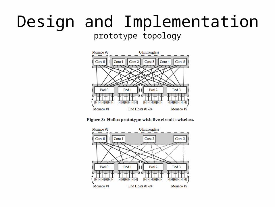
Design and Implementationprototype topology

Design and ImplementationSoftware
• Topology manager– Edmonds algorithm– runs on single server
• Circuit Switch Manager– programmable circuit switching software running on optical GLIMMERGLASS running in
synchronous mode (available to process multiple circuit switching request)
• Pod Switch Manager– runs on each pod switch– manages flow table and interfacing with the topology manager– uses L2 forwarding- supports multipath forwarding using Link Aggregation Groups– LIMITATION : cannopt split traffic over both the packet switch and cirtcuit switch travelling to the
same port ( monaco's limitation )
• Basic Workflow1. Control Loop
• TM issues commands to get the octet-counter matrix to the PSM• each flow classified into mouse or elephant (<15Mb/s or up)
2. Estimate Demand- flow-rate matrix not good- max-min fair bandwidth is better3. Compute New Topology- objective : maximize throughput- max-weighted matching
problems on bipartite graphs4. notify down, change topology, notify up

Evaluation
• Pod-Level Stride (PStride)– Each host in a source pod i sends 1 TCP flow to each
host in a destination pod j = (i+k) mod 4 with k rotating from 1 to 3 after each stability period
– Pod rotation• Host-Level Stride (HStride)– Each host i (numbered from 0 to 23) sends 6 TCP flows
simultaneously to host j = (i+6+k) mod 24 with k rotating from 0 to 12 after each stability period.
• Random

EvaluationDebouncing and EDC
• Debouncing– ポート切り替えの際に発生する,ケーブルシグナルの slow booting– Avoids routing problems, etc.– Switch の仕様
• Electronic Dispersion Compensation (EDC) algorithm– Circuit switching delay time, which removes the noise from light traveling a long time
両方 DISABLEしたらスループットあがったよ!

EvaluationThroughput VS Stability
フローの切り替えが早いとスループットが下がる

Evaluationetc.

Scalable Flow-Based Networking with DIFANE
Minlan Yu ∗ Jennifer Rexford ∗ Michael J. Freedman ∗ Jia Wang† ∗ Princeton University, Princeton, NJ, USA † AT&T Labs - Research, Florham Park, NJ,
USA

概要
• 背景– DCN の複雑化 -> スイッチ設定の複雑化– flow based switches• fexible policies ; dropping, forwarding packets based on
rules that match on bits in the packet header
• 目的– creating a dynamic flow based switching
architecture

Existing Flow based Switch Configuration
• existing control schemes– sends the microflow's first packet to a centralizaed
controller, which issues a rule to the switch software
– centralized mechanic = bottleneck– keep all traffic in the data plane for better
performance and scalability
switches should be able to do this on their own

DIFANE DESIGN DECISIONS• Reducing Overhead of Cache Misses
– Process all packets in the data plane (hardware)– rule caching with wildcards
• Scaling to Large Networks and Many Rules• Partition and distribute the flow rules
– one primary controller that manages policy, computes rules, and divides the rues across the switches– each switch handles the portion of the rule space
• -consistent topology information distribution with the link-state protocol– link-state protocol among the switches

DIFANE Architecture• Basic work flow
1. ingress switch recieves packet2. redirects to the authority switches 3. authority switch tells ingress switch to cache the result 4. next packets could be sent directly to the egress switch
• Rule partition and allocation– precompute low-level-rules
• the controller pre-computes the low-level rules based on the high-level policies by substituting high-level names (netowork addresses)
• rule spaces are partitioned -> each portion of rule space to one or more authority switches

Network Dynamics への対応• change to rules
– when administrators modify the policies– network events affect the mapping between policies and rules (failures?
• Topology Dynamics- authority switch failure– routing protocol sends failure msg of specific auth switch– partitions rules regarding the authority switch get recomputed, redirected to
backup switch– addition recovery
• the controller randomly selects auth switch, divides is partition in 2, and let the new one handle the half
• Host Mobility– installing rules at new ingress switch on demand-removing rules from old
ingress switch by TIMEOUT

WildCard あれこれ• caching wildcard rules
– overlapping rules can cause trouble– ingress switches could only cache the highest priority rules– to prevent conflicting cache rules, authority switches are only able to install caching rules in its own flow range
• Partitioning wildcard rules– allocating non-overlapping flow ranges to the authority switches- splitting the rules so that each rule only belongs to
one authority switch– cuts to align with rule boundaries- duplicating authority rules to reduce stretch