‘C’ The Advantage - C-Aire Compressors may result in physical harm and/or property damage. ......
16
‘C’ The Advantage
Transcript of ‘C’ The Advantage - C-Aire Compressors may result in physical harm and/or property damage. ......

‘ C ’ T h e A d va n t a g e

V: VerticalH: HorizontalP: PortableD: Duplex
TANK ORIENTATION
1: Single Phase3: Three PhaseG: Gas Drive
PHASE
115230 (Includes 208)
460
VOLTAGE
FP: Fully Packaged
UPGRADE OPTIONS
Includes:- Aftercooler- Automatic Tank Drain- Installation Kit
015: 1.5030: 3.0050: 5.0075: 7.5100: 10.0150: 15.0
130: 13.0
HORSE POWER
GAS DRIVE
ELECTRIC020: 20060: 60080: 80120: 120240: 240
TANK SIZE
GALLONS
120 230 FPE075 D 1APRODUCT NUMBERING SYSTEM
*Not all combinations are possible
E: Electronic Controller For Duplex Units
The compressor you have purchased is a combination of nearly 100 different components, all of which have been carefully designed, engineered, and assembled to ensure a long, dependable, trouble-free life. The product has been fully tested at the factory and has gone through quality-control inspection prior to shipping.
Like any mechanical piece of equipment, it is necessary to fully understand the proper use of its operation and application. Misuse of this valuable and helpful air-power source may shorten its expected life as well as void the warranty of the entire unit. We ask you take the time to read this manual to ensure the dependable service you can expect from your C-Aire compressor.
Failure to do so can cause serious injury and may void all warranties.
Please take special notice of the safety precautions and safety information contained in this manual. Compressed air, like electricity, is a very helpful and necessary tool. However, compressed air can be extremely dangerous and harmful when it is not understood or is misused.
C-Aire Inc.380 West 1st StreetDresser, WI 54009
651.462.3440 [email protected]
INTRODUCTION
TABLE OF CONTENTSIntroduction.........................................................................1 Product Numbering System .................................................1 Safety ..................................................................................2 Receiving and Inspection ....................................................2 Installation..........................................................................2 Electrical .............................................................................3 Parts Identification..............................................................7 Lubrication ..........................................................................9
Start-up ............................................................................10Maintenance .....................................................................10Valves and Switches .........................................................11 Pulley/Sheave Alignment and Belt Tension ........................11 Warranty ............................................................................12 Troubleshooting .................................................................13 Installation Checklist ........................................................14
1

2
DEFINITIONS
DANGER: Indicates a hazardous situation that, if not avoided, will result in death or serious injury.
WARNING: Indicates a hazardous situation that, if not avoided, could result in death or serious injury.
CAUTION: Indicates a situation that will or could cause minor injury or property damage.
GENERAL PRECAUTIONS Read the Owner’s Manual before operating.
DANGER: Do not use compressed air for breathing air applications. Beware of high voltage: disconnect lockout/tagout electric supply before servicing. Ground compressor per codes.
WARNING: Beware of high-pressure air: do not bypass, modify, or remove safety/relief valves. Beware of hot surfaces: allow unit to cool before servicing. Do not operate with safety guards removed.
CAUTION: Never operate the compressor near flammable liquids or vapors. Do not direct the air stream at body. Drain tank air every day to decrease risk of bursting.
NOTE: Per UL 1450:46.17 C-Aire recommends a maximum of 70% duty cycle for its compressors.
Upon receipt, inspect the unit for damage and missing parts. If either is apparent, make notations on the delivery receipt, before signing the receipt. Ask the carrier how to file a claim for shipping damages.
If concealed damage is discovered (after receiving the unit), notify the carrier within 15 days of receipt, in writing.
WARNING: Be sure lifting equipment is capable of supporting the weight of the unit. Lift the unit by the shipping skid only. Do not walk under or work under the unit while it is suspended.
SELECTING A LOCATION:C-Aire compressors are to be installed and operated in a clean, dry, well-lighted, and well-ventilated area, not less than 12 inches from walls or other equipment.
Provide at least 1,000 cubic feet of fresh air per 5 hp.
Ideal operating temperatures are between 32°F and 100°F.
Avoid excessively humid areas, as moisture may form in the pump, producing sludge and causing moving parts to wear prematurely.
SAFETY
RECEIVING AND INSPECTION
INSTALLATION
(INSTALLATION CONTINUED ON NEXT PAGE)

3
CAUTION: If temperatures consistently drop below 32° F, install the compressor in a heated area.
CAUTION: Never operate the compressor in temperatures below 20°F or above 104°F.
WARNING: A compressor should never be used in an area where toxic, corrosive, or volatile agents may be present.
MOUNTING THE COMPRESSOR
CAUTION: Remove the compressor from the shipping skid before mounting.
ANTI-VIBRATION INSTALLATIONBe sure your C-Aire compressor is mounted on a level, concrete floor, preferably using anti-vibration pads.
When installing anchor bolts from your installation kit, all anchor bolts should be finger tight only.
All vertical tank units must be safely anchored.
CAUTION: Over-tightening bolts or mounting to an uneven surface could cause damage to the compressor. CAUTION: Never operate this unit more than 15 degrees off level, and never move it while it is operational. CAUTION: When mounting gas-drive compressors to truck beds, install so as not to create stress to the tank. Truck beds do bend, which can cause damage to the tank if it is mounted directly to the truck bed.
INLET AND DISCHARGE PIPING
CAUTION: Do not operate unit without inlet-air filtration.
If the air is dirty, pipe the filter to a source of clean air.
Do not install piping with a diameter lower than that of the pump intake.
CAUTION: Do not use PVC plastic in the discharge line.
Use hand-welded or threaded steel or copper pipes and cast-iron fittings that are safe for the discharge pressure and temperature.
WARNING: Compressor installation must be performed by a qualified electrician in accordance with the National Electrical Code (NEC) or the Canadian Electrical Code (CEC), the National Electrical Safety Code (NESC) OSHA code, and/or any local or state codes having precedence.
Be sure of proper wire sizing and that the circuit breaker and the distance from the breaker is within suggested range.
Confirm your electrical-supply voltage matches what is required for the motor. If using a three-phase motor, any unreasonable voltage imbalance between the legs must be eliminated and any high or low voltage corrected to prevent excessive current draw.
ELECTRICAL
1/2” LOCKNUT (FINGER TIGHT ONLY)
1/2” FLAT WASHER
TANK FOOT
ISOLATOR
1/2” FLOOR STUD(PROVIDED BY CUSTOMER)
ANTI-VIBRATION INSTALLATION
TANK UNIT ANCHORED
(ELECTRICAL CONTINUED ON NEXT PAGE)
44
WARNING: The compressor must be grounded. Grounding reduces the risk of electric shock. Certain C-Aire models are equipped with a cord that has a grounding wire with a grounding plug. The plug must be plugged into an outlet that is installed and grounded in accordance with all local codes and ordinances.
WARNING: Improper installation of the grounding plug will result in a risk of electric shock. When repair or replacement of the cord or plug is required, do not connect the grounding wire to either flat-blade terminal. The insulated wire with a green outer surface and yellow stripes is the grounding wire.
WARNING: Duplex compressors: this product has more than one connection to the power supply. To reduce the risk of electrical shock, disconnect all such connections before servicing.
NOTE: The installation, electric motor, wiring, and all electrical controls must be in accordance with NFPA 70-1996 National Electric Code, National Electric Safety Code, and state and local codes. Failure to abide by the national, state, and local codes may result in physical harm and/or property damage.
DANGER: High voltage may cause personal injury or death. Disconnect and lockout/tagout, per OSHA regulation 1910.147, all electrical power supplies before opening the electrical enclosure or servicing.
DANGER: Never assume a compressor is safe to work on if it is not operating. It could restart at any time. Always disconnect/lockout/tagout before servicing.
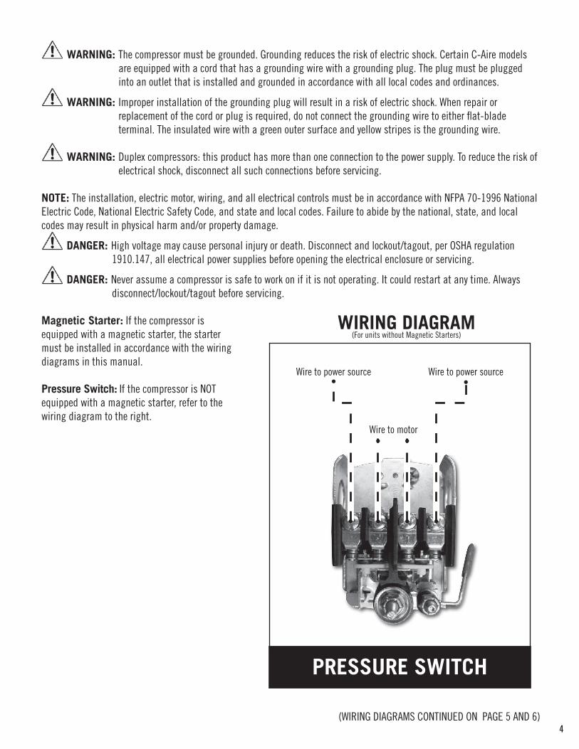
Magnetic Starter: If the compressor is equipped with a magnetic starter, the starter must be installed in accordance with the wiring diagrams in this manual.
Pressure Switch: If the compressor is NOT equipped with a magnetic starter, refer to the wiring diagram to the right.
WIRING DIAGRAM(For units without Magnetic Starters)
PRESSURE SWITCH
Wire to power source Wire to power source
Wire to motor
(WIRING DIAGRAMS CONTINUED ON PAGE 5 AND 6)
5
QUESTIONS / HELP? Call C-Aire at 651.462.3440
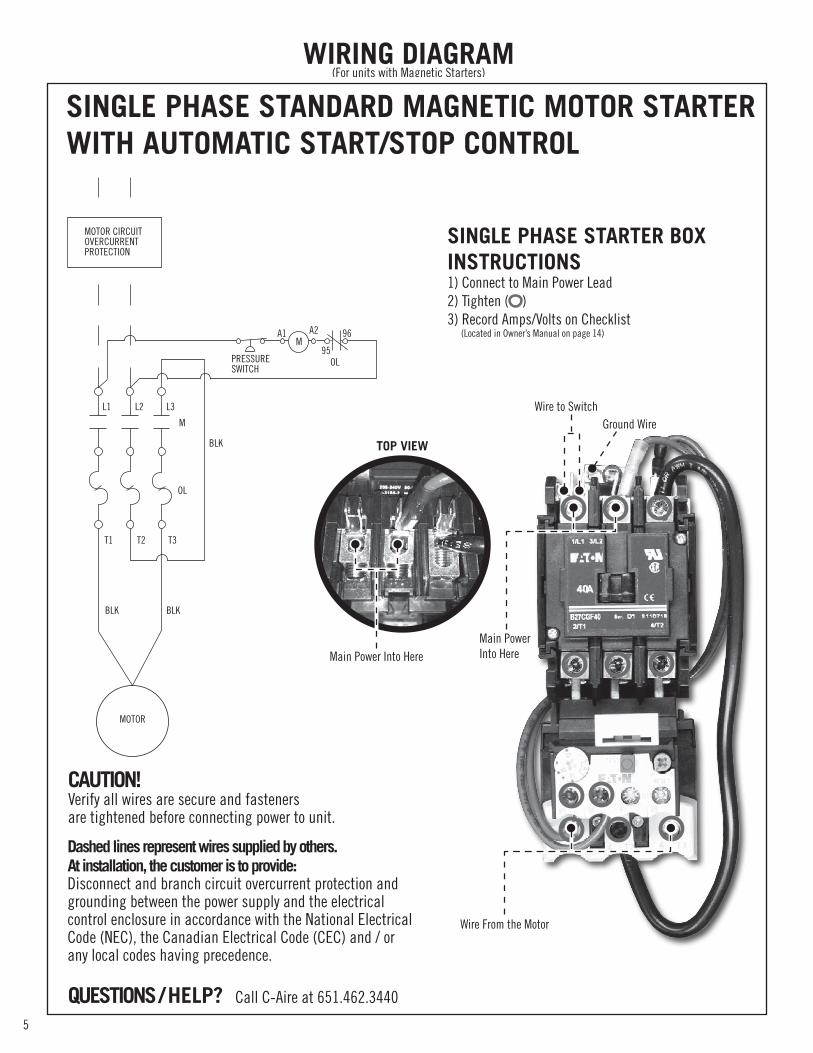
SINGLE PHASE STARTER BOX INSTRUCTIONS1) Connect to Main Power Lead2) Tighten ( )3) Record Amps/Volts on Checklist (Located in Owner’s Manual on page 14)
TOP VIEW
Main Power Into HereMain Power Into Here
Wire to SwitchGround Wire
Wire From the Motor
CAUTION!Verify all wires are secure and fasteners are tightened before connecting power to unit.
Dashed lines represent wires supplied by others.At installation, the customer is to provide:Disconnect and branch circuit overcurrent protection andgrounding between the power supply and the electrical control enclosure in accordance with the National ElectricalCode (NEC), the Canadian Electrical Code (CEC) and / orany local codes having precedence.
SINGLE PHASE STANDARD MAGNETIC MOTOR STARTER WITH AUTOMATIC START/STOP CONTROL
PRESSURESWITCH
MOTOR
BLKBLK
BLK
OL
OL
L1 L2 L3
M
T1 T2 T3
MOTOR CIRCUITOVERCURRENTPROTECTION
MA1 96A2
95
WIRING DIAGRAM(For units with Magnetic Starters)

6
QUESTIONS / HELP? Call C-Aire at 651.462.3440
CAUTION!Verify all wires are secure and fasteners are tightened before connecting power to unit.
Dashed lines represent wires supplied by others.At installation, the customer is to provide:Disconnect and branch circuit overcurrent protection andgrounding between the power supply and the electrical control enclosure in accordance with the National ElectricalCode (NEC), the Canadian Electrical Code (CEC) and / orany local codes having precedence.
THREE PHASE STANDARD MAGNETIC MOTOR STARTER WITH AUTOMATIC START/STOP CONTROL
PRESSURESWITCH
MOTOR
BLKBLK BLK
OL
OL
L1 L2 L3
M
T1 T2 T3
MOTOR CIRCUITOVERCURRENTPROTECTION
MA1 96A2
95
(OPTIONAL)
BLKBLK
THREE PHASE STARTER BOX INSTRUCTIONS1) Connect to Main Power Lead2) Tighten ( )3) Record Amps/Volts on Checklist (Located in Owner’s Manual on page 14)
Wire to switch
Ground Wire
Main Power Into Here
Wire From the Motor
TOP VIEW
Main Power Into Here
WIRING DIAGRAM(For units with Magnetic Starters)
Air Filter
Electric Motor
Safety Relief Valve
Pressure Gauge
Pressure Switch
OFF
AUTO
Magnetic Starter
Belt Guard
Unloader Valve
Discharge Tube
Ball Valve
Serial Tag
Model A075V080-3230
Serial # CA201200629
MFG # 20120315
C-Aire (800) 762-2247
Motor: MR EM3219THP: 7.5
Pump: PM F 95W2Oil Capacity: 2.23QTC-Aire Synthetic Compressor Oil Recommended
Replacement PartsAir Filter: 210-0952Check Valve: BR c-7575-ST
Check Valve
Pump
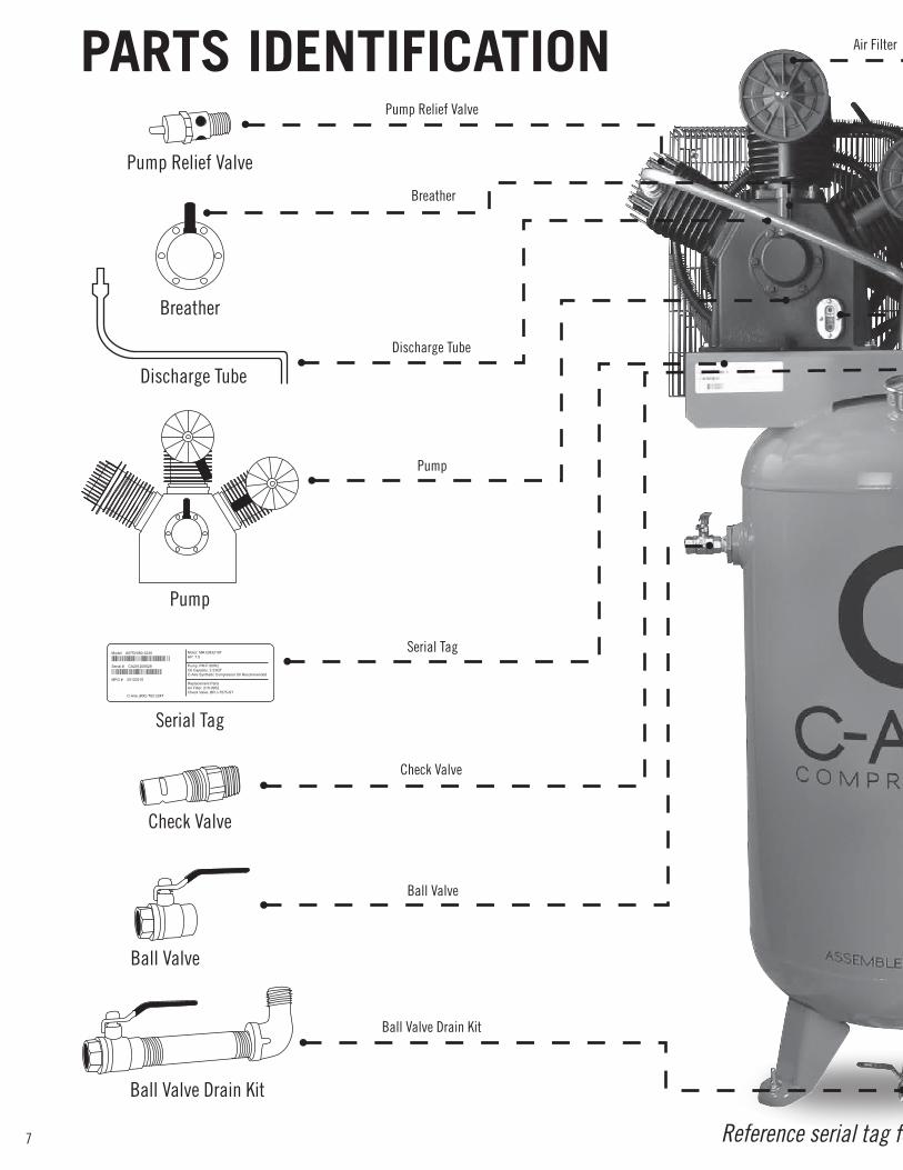
Ball Valve Drain Kit
Pump Relief Valve
Breather
Reference serial tag for specific part numbers
Pump Relief Valve
Breather
Discharge Tube
Pump
Serial Tag
Ball Valve
Check Valve
Ball Valve Drain Kit Unloader Valve
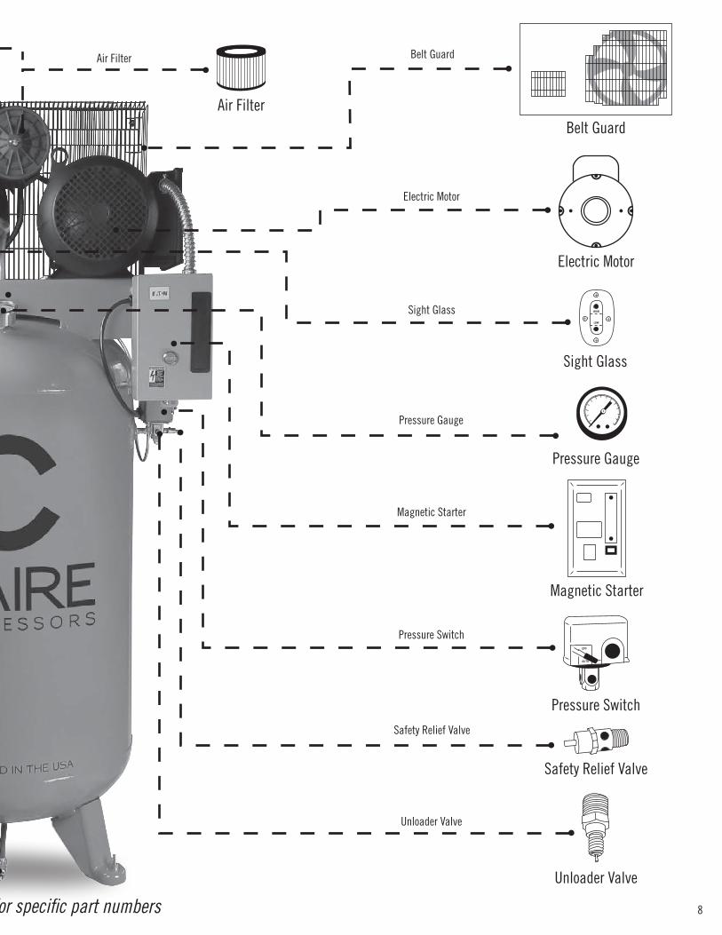
Pressure Gauge
Safety Relief Valve
Pressure Switch
Magnetic Starter
Electric Motor
Belt Guard
Air Filter
Air Filter
Sight Glass
Sight Glass
PARTS IDENTIFICATION
+
+
HIGH
LOW+ +
7
Air Filter
Electric Motor
Safety Relief Valve
Pressure Gauge
Pressure Switch
OFF
AUTO
Magnetic Starter
Belt Guard
Unloader Valve
Discharge Tube
Ball Valve
Serial Tag
Model A075V080-3230
Serial # CA201200629
MFG # 20120315
C-Aire (800) 762-2247
Motor: MR EM3219THP: 7.5
Pump: PM F 95W2Oil Capacity: 2.23QTC-Aire Synthetic Compressor Oil Recommended
Replacement PartsAir Filter: 210-0952Check Valve: BR c-7575-ST
Check Valve
Pump
Ball Valve Drain Kit
Pump Relief Valve
Breather
Reference serial tag for specific part numbers
Pump Relief Valve
Breather
Discharge Tube
Pump
Serial Tag
Ball Valve
Check Valve
Ball Valve Drain Kit Unloader Valve
Pressure Gauge
Safety Relief Valve
Pressure Switch
Magnetic Starter
Electric Motor
Belt Guard
Air Filter
Air Filter
Sight Glass
Sight Glass
PARTS IDENTIFICATION
+
+
HIGH
LOW+ +
8

9
ALL C-AIRE COMPRESSORS COME FACTORY FILLED WITH SYNTHETIC OIL WHICH REQUIRES NO BREAK-IN PERIOD.
Oil Level: Check the oil level before each start-up. The oil level must be maintained to the center of the sight glass (unless there is an oil-level mark on the sight glass to indicate otherwise).
NOTE: The oil may turn black before the first oil change due to packaging oil in all new pumps. The black color does not necessitate an oil change prior to first-year annual maintenance as recommended when using synthetic oil.
The oil drain plug is located at the base of the pump (see diagram). The oil fill plug is located at the top of the pump crankcase (see diagram).
CAUTION: Never remove either oil plug while the compressor is running.
PERFORMING AN OIL CHANGE 1. Remove the oil drain plug, and allow the lubricant to drain into a suitable container. 2. Replace the oil drain plug. 3. Remove the oil fill plug, and fill the crankcase with oil.
NOTE: Oil fill capacity is listed on the unit’s serial tag.
LUBRICATION
Oil Sight Glass
Oil Drain Plug
Crankcase Breather
Oil Fill Plug
10
When the oil level is half way in the sight glass - the crankcase is full
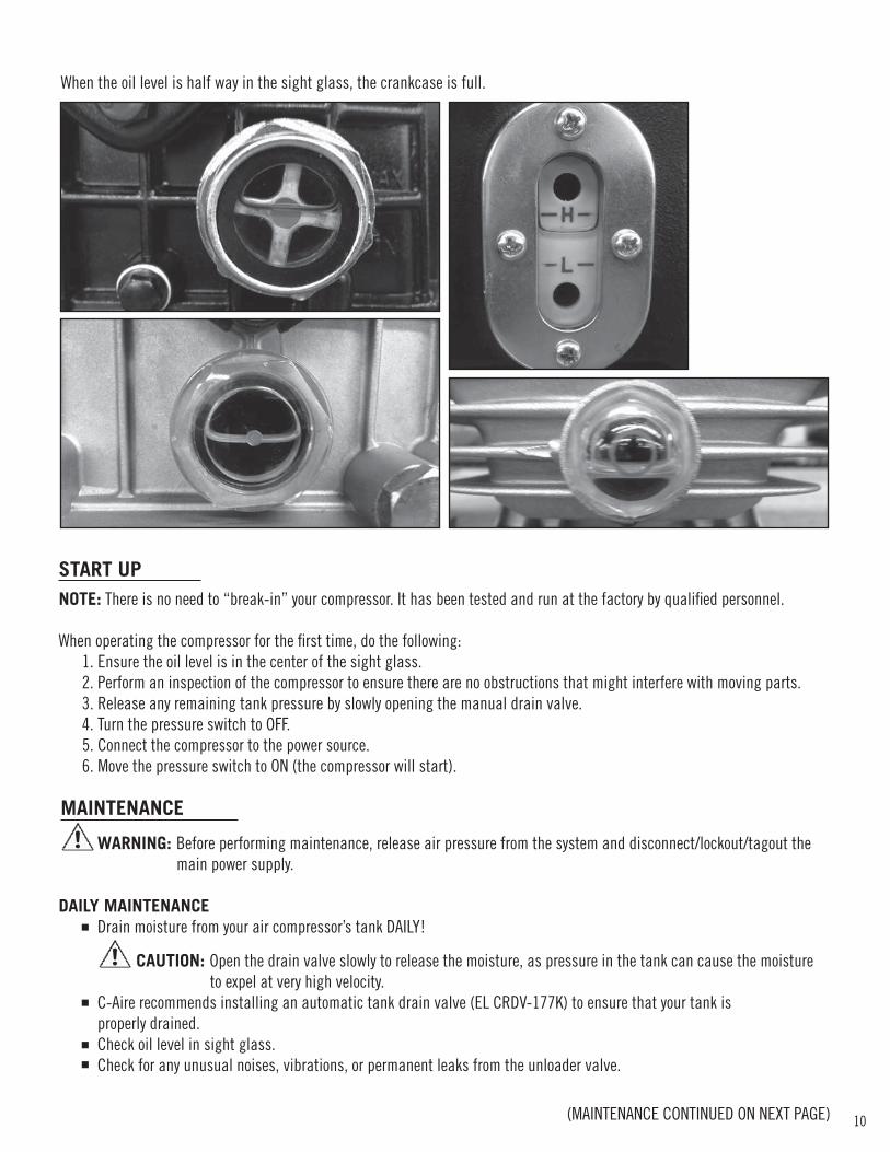
NOTE: There is no need to “break-in” your compressor. It has been tested and run at the factory by qualified personnel.
When operating the compressor for the first time, do the following: 1. Ensure the oil level is in the center of the sight glass. 2. Perform an inspection of the compressor to ensure there are no obstructions that might interfere with moving parts. 3. Release any remaining tank pressure by slowly opening the manual drain valve. 4. Turn the pressure switch to OFF. 5. Connect the compressor to the power source. 6. Move the pressure switch to ON (the compressor will start).
WARNING: Before performing maintenance, release air pressure from the system and disconnect/lockout/tagout the main power supply.
DAILY MAINTENANCE Drain moisture from your air compressor’s tank DAILY!
CAUTION: Open the drain valve slowly to release the moisture, as pressure in the tank can cause the moisture to expel at very high velocity. C-Aire recommends installing an automatic tank drain valve (EL CRDV-177K) to ensure that your tank is properly drained. Check oil level in sight glass. Check for any unusual noises, vibrations, or permanent leaks from the unloader valve.
START UP
MAINTENANCE
When the oil level is half way in the sight glass, the crankcase is full.
(MAINTENANCE CONTINUED ON NEXT PAGE)
11
VALVES AND SWITCHES
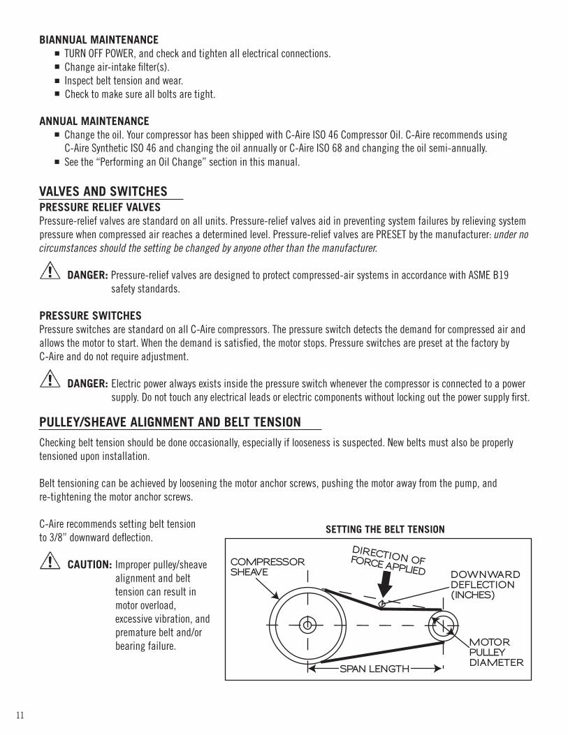
PULLEY/SHEAVE ALIGNMENT AND BELT TENSION
TURN OFF POWER, and check and tighten all electrical connections. Change air-intake filter(s). Inspect belt tension and wear. Check to make sure all bolts are tight.
COMPRESSORSHEAVE DOWNWARD
DEFLECTION(INCHES)
MOTOR PULLEY DIAMETER
SPAN LENGTH
DIRECTION OF FORCE APPLIED
SETTING THE BELT TENSION
C-Aire Synthetic ISO 46 and changing the oil annually or C-Aire ISO 68 and changing the oil semi-annually.

12
C-Aire Inc. warrants its compressors to be free from defects in material and workmanship subject to the following provisions:
STANDARD WARRANTY DURATION: The Standard Warranty lasts 12 months from date of purchase.
EXTENDED WARRANTY DURATION: Three year Extended Warranties are available for the C-Aire A050, A075, A100, A130, and A150 series compressors, which extend the warranty from 12 months to 36 months from date of purchase. To obtain an Extended Warranty, purchase an Extended Warranty kit the same day as your compressor, register your Extended Warranty with C-Aire within 10 days of purchase, and perform the recommended maintenance on schedule.
REGISTERING YOUR EXTENDED WARRANTY: Your Extended Warranty may be registered using the instructions in your Extended Warranty kit any of these three ways:A) Online at www.c-aireinc.comB) Calling us at 1-800-762-2247 or 651-462-3440C) Faxing us at 651-462-1232
WHAT THE WARRANTY COVERS DURING THE WARRANTY DURATION: Warranties cover all compressor components except those items and in those situations listed in “What Is Excluded From Warranty Coverage.”
WHAT IS EXCLUDED FROM THE WARRANTY COVERAGE: A) Air-intake filters and compressor oil, which are maintenance items.B) Failure due to improper installation, including absence of mounting pads, and insufficient power.C) Oil leaks 60 days after purchase (they are covered in the 60 days following purchase).D) Freight-damaged items (REJECT THE SHIPMENT or note damage on bill of lading).E) Any labor, freight, or transportation charges not pre-approved by C-Aire.F) Labor charges incidental to installation, electrical connections, repair, service, adjustment, removal, or replacement.G) Misuse or abuse.H) C-AIRE HAS NO OBLIGATION UNDER THESE WARRANTIES OR OTHERWISE (REGARDLESS OF THE FORM OF ACTION) FOR
SPECIAL, INDIRECT, CONSEQUENTIAL, OR INCIDENTAL DAMAGES, INCLUDING WITHOUT LIMITATION, LOSS OF USE, LOST PROFITS, AND LOST INCOME, WHETHER SUFFERED BY THE BUYER OR A THIRD PARTY.
C-AIRE’S OBLIGATIONS: C-Aire will repair or replace, at C-Aire’s option, defective parts, pay reasonable labor costs of replacing or repairing the defective parts, and pay ground freight for the return of defective parts and shipment of the replacement parts. ALL LABOR AND FREIGHT MUST BE PRE-APPROVED AND ARRANGED BY C-AIRE.
PURCHASER’S OBLIGATION: A) Properly install and start up the compressor using the checklist located at the back of this owner’s manual.
(Keep the Installation Checklist for future reference.)B) Ensure the compressor is sized properly for the application.
(The compressor should run no more than 7 out of 10 minutes on average.)C) Maintain proof of purchase and the Installation Checklist.D) Register your Extended Warranty (if applicable).
WARRANTY CLAIMS: Please contact C-Aire at 1-800-762-2247 or 651-462-3440. Please have your completed Installation Checklist available.
WARRANTY
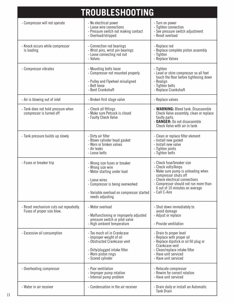
- No electrical power- Loose wire connections- Pressure switch not making contact- Overload/stripped
- Connection rod bearings- Wrist pins, wrist pin bearings- Loose connecting rod nut- Valves
- Mounting bolts loose- Compressor not mounted properly
- Pulley and Flywheel misaligned- Belt loose- Bent Crankshaft
- Broken first stage valve
- Check all fittings- Make sure Petcock is closed- Faulty Check Valve
- Dirty air filter- Blown cylinder head gasket- Worn or broken valves- Air leaks- Loose belts
- Motor overload
- Malfunctioning or improperly adjusted pressure switch or pilot valve- High ambient temperature
- Wrong size fuses or breaker- Wrong size wire- Motor starting under load
- Loose wires- Compressor is being overworked
- Variable overload on compressor started needs adjusting
- Compressor will not operate
- Knock occurs while compressor is loading
- Compressor vibrates
- Air is blowing out of inlet
- Tank does not hold pressure when compressor is turned off
- Tank pressure builds up slowly
- Reset mechanism cuts out repeatedly. Fuses of proper size blow.
- Fuses or breaker trip
- Turn on power- Tighten connection- See pressure switch adjustment- Reset overload
- Replace rod- Replace complete piston assembly- Tighten- Replace Valves
- Tighten- Level or shim compressor so all feet touch the floor before tightening down- Realign- Tighten belts- Replace Crankshaft
- Replace valves
- WARNING: Bleed tank. Disassemble Check Valve assembly, clean or replace faulty parts.- DANGER: Do not disassemble Check Valve with air in tank
- Clean or replace filter element- Install new gasket- Install new valve- Tighten joints- Tighten belts
- Shut down immediately to avoid damage- Adjust or replace
- Provide ventilation
- Check fuse/breaker size- Check volts/Amps- Make sure pump is unloading when compressor shuts off- Check electrical connections- Compressor should not run more than 6 out of 10 minutes on average- Call C-Aire
- Too much oil in Crankcase- Improper weight of oil- Obstructed Crankcase vent
- Dirty/plugged intake filter- Worn piston rings- Scored cylinder
- Excessive oil consumption - Drain to proper level- Replace with proper oil- Replace dipstick or oil fill plug or Crankcase vent- Clean/replace intake filter- Have unit serviced- Have unit serviced
- Poor ventilation- Improper pump rotation- Internal pump problem
- Overheating compressor - Relocate compressor- Rewire for correct rotation- Have unit serviced
- Condensation in the air receiver- Water in air receiver - Drain daily or install an Automatic Tank Drain
TROUBLESHOOTING
13

14
Carefully inspect the unit for damage that may have occurred during shipping. If damage has occurred, it should be noted on the freight carrier’s bill of lading. (The manufacturer of this product is in no way responsible for damage or losses resulting from damage during shipping. All claims must be filed through the carrier’s claim department.)
Compressor is installed over 12” from any wall
There is more than 12” from the top of the compressor pump to the ceiling
The compressor is located in a well ventilated area
For workshops under jurisdiction of OSHA; OSHA requires compressors to be anchored to the floor. - 3 Leg bolts are hand tightened to the floor - 1 Leg bolt left loose - Use a level and shims to ensure the compressor top plate is perfectly level
Mount compressor on anti-vibration/mounting pads. Failure to do so will cause premature tank leaks and void warranty.
Electrical connections must be made by licensed electrician
Use the wiring instructions to make electrical connections
Ensure the correct gauge wire is used based on the Amp draw and distance to the circuit breaker box - Distance to circuit box: - Gauge wire used from box to compressor: - Amp rating for circuit breaker:
Check Volts before compressor is started up: - Single Phase: - Three Phase: L1:L2 L1:L3 L2:L3
Check Amps and Volts at start up: - Single Phase Volts: - Three Phase Volts: L1:L2 L1:L3 L2:L3 - Single Phase Amps: - Three Phase Amps: L1:L2 L1:L3 L2:L3
Check Amps and Volts at maximum pressure before the compressor shuts off: - Single Phase Volts: - Three Phase Volts: L1:L2 L1:L3 L2:L3 - Single Phase Amps: - Three Phase Amps: L1:L2 L1:L3 L2:L3
Be sure the pump unloads pressure, either at shut down if it is a Mechanical Unloader or immediately at start up if it is an Electronic Head Unloader.
Check rotation of the flywheel. Be sure its rotation matches the direction of the arrow which refers to the top loop of the belt(s).
INSPECT FOR DAMAGE
LOCATION AND INSTALLATION OF COMPRESSOR
ELECTRICAL
COMPONENT FUNCTION
THREE PHASE UNITS ONLY
In order to validate the warranty on your compressor, C-Aire requires this checklist be completed and kept for reference.
INSTALLATION CHECKLIST

MODEL
SERIAL #
MFG. #
Make a permanent record of the Model and Serial Number of your compressor by filling in the fields above.You’ll save time and expense by including this reference identification on replacement part orders.
380 West 1st Street, Dresser, WI 54009 // 800.762.2247//651.462.3440//www.c-aireinc.com