C-Series Concealed (Ducted) Indoor and Outdoor Units ... · PDF fileC-Series Concealed...
64
September 2015 MS-PRC020A-EN C-Series Concealed (Ducted) Indoor and Outdoor Units Indoor unit model number: 4MUD******** Outdoor unit model number: 4TUK******** Product Catalog
Transcript of C-Series Concealed (Ducted) Indoor and Outdoor Units ... · PDF fileC-Series Concealed...
September 2015 MS-PRC020A-EN
C-SeriesConcealed (Ducted) Indoor and Outdoor Units
Indoor unit model
number: 4MUD********
Outdoor unit model number: 4TUK********
Product Catalog

©2015 Trane All rights reserved MS-PRC020A-EN
IntroductionTrane® C-Series ductless systems offer heating and cooling capacities ranging from 1.5 to 4 tons to precisely meet the
requirements of indoor spaces while delivering high energy efficiency—up to 20 SEER. A variety of indoor fan coil unit
options are available in both ceiling cassette and concealed designs, so your Trane ductless system can be perfectly
tailored to the requirements of the space. Trane C-Series systems support pipe runs of up to 98 vertical ft (29.9 m), and
up to 245 total ft (74.7 m). All C-Series systems are rated for cooling operation to 0°F (-17.8°C) and heating operation to
-4°F (-20°C).
Suitable for a wide variety of applications, Trane C-Series systems can reliably deliver precise temperature control to
maintain comfort, as well as ensure the reliability of heat-generating equipment like computer servers, making them
perfect for applications like small remote facilities on larger campuses, data centers, machine rooms and more. Trane C-
Series systems are also a perfect supplement to larger Trane VRF systems, with the same controls available to both
systems.
CopyrightThis document and the information in it are the property of Trane, and may not be used or reproduced in whole or in
part without written permission. Trane reserves the right to revise this publication at any time, and to make changes to
its content without obligation to notify any person of such revision or change.
TrademarksAll trademarks referenced in this document are the trademarks of their respective owners.
Related DocumentsFor C-Series Cassette Indoor Unit Systems, refer to MS-PRC019*–EN.
MS-PRC020A-EN 3
Features and Benefits. . . . . . . . . . . . . . . . . . . . . . . . . . . . . . . . . . . . . . . . . . . . . . . . . . . . . . . . . . . . . . . . . . . . . . . . . . . . . 5
Mechanical Specification . . . . . . . . . . . . . . . . . . . . . . . . . . . . . . . . . . . . . . . . . . . . . . . . . . . . . . . . . . . . . . . . . . . . . . . . . 6
Outdoor Unit . . . . . . . . . . . . . . . . . . . . . . . . . . . . . . . . . . . . . . . . . . . . . . . . . . . . . . . . . . . . . . . . . . . . . . . . . . . . . . . . . . . 6
Indoor Unit . . . . . . . . . . . . . . . . . . . . . . . . . . . . . . . . . . . . . . . . . . . . . . . . . . . . . . . . . . . . . . . . . . . . . . . . . . . . . . . . . . . . . 6
Indoor Unit Model Number Description. . . . . . . . . . . . . . . . . . . . . . . . . . . . . . . . . . . . . . . . . . . . . . . . . . . . . . . . . . . 8
Outdoor Unit Model Number Descriptions. . . . . . . . . . . . . . . . . . . . . . . . . . . . . . . . . . . . . . . . . . . . . . . . . . . . . . . . 9
Controls . . . . . . . . . . . . . . . . . . . . . . . . . . . . . . . . . . . . . . . . . . . . . . . . . . . . . . . . . . . . . . . . . . . . . . . . . . . . . . . . . . . . . . . . . 10
Accessories. . . . . . . . . . . . . . . . . . . . . . . . . . . . . . . . . . . . . . . . . . . . . . . . . . . . . . . . . . . . . . . . . . . . . . . . . . . . . . . . . . . . . . 11
Product Specification . . . . . . . . . . . . . . . . . . . . . . . . . . . . . . . . . . . . . . . . . . . . . . . . . . . . . . . . . . . . . . . . . . . . . . . . . . . . 12
Capacity Tables . . . . . . . . . . . . . . . . . . . . . . . . . . . . . . . . . . . . . . . . . . . . . . . . . . . . . . . . . . . . . . . . . . . . . . . . . . . . . . . . . . 19
Unit Dimensions . . . . . . . . . . . . . . . . . . . . . . . . . . . . . . . . . . . . . . . . . . . . . . . . . . . . . . . . . . . . . . . . . . . . . . . . . . . . . . . . . 37
Indoor Unit Dimensions . . . . . . . . . . . . . . . . . . . . . . . . . . . . . . . . . . . . . . . . . . . . . . . . . . . . . . . . . . . . . . . . . . . . . . . . 37
Outdoor Unit Dimensions . . . . . . . . . . . . . . . . . . . . . . . . . . . . . . . . . . . . . . . . . . . . . . . . . . . . . . . . . . . . . . . . . . . . . . 39
Wiring Diagrams. . . . . . . . . . . . . . . . . . . . . . . . . . . . . . . . . . . . . . . . . . . . . . . . . . . . . . . . . . . . . . . . . . . . . . . . . . . . . . . . . 40
Indoor Unit . . . . . . . . . . . . . . . . . . . . . . . . . . . . . . . . . . . . . . . . . . . . . . . . . . . . . . . . . . . . . . . . . . . . . . . . . . . . . . . . . . . . 40
Outdoor Unit . . . . . . . . . . . . . . . . . . . . . . . . . . . . . . . . . . . . . . . . . . . . . . . . . . . . . . . . . . . . . . . . . . . . . . . . . . . . . . . . . . 42
Sound Levels . . . . . . . . . . . . . . . . . . . . . . . . . . . . . . . . . . . . . . . . . . . . . . . . . . . . . . . . . . . . . . . . . . . . . . . . . . . . . . . . . . . . 44
Indoor Unit . . . . . . . . . . . . . . . . . . . . . . . . . . . . . . . . . . . . . . . . . . . . . . . . . . . . . . . . . . . . . . . . . . . . . . . . . . . . . . . . . . . . 44
Outdoor Unit . . . . . . . . . . . . . . . . . . . . . . . . . . . . . . . . . . . . . . . . . . . . . . . . . . . . . . . . . . . . . . . . . . . . . . . . . . . . . . . . . . 46
Airflow Diagrams . . . . . . . . . . . . . . . . . . . . . . . . . . . . . . . . . . . . . . . . . . . . . . . . . . . . . . . . . . . . . . . . . . . . . . . . . . . . . . . . 48
How to Interpret P-Q Tables and Graphs. . . . . . . . . . . . . . . . . . . . . . . . . . . . . . . . . . . . . . . . . . . . . . . . . . . . . . . . . . 48
4MUD4518A10N0A . . . . . . . . . . . . . . . . . . . . . . . . . . . . . . . . . . . . . . . . . . . . . . . . . . . . . . . . . . . . . . . . . . . . . . . . . . . . 49
4MUD4524A10N0A . . . . . . . . . . . . . . . . . . . . . . . . . . . . . . . . . . . . . . . . . . . . . . . . . . . . . . . . . . . . . . . . . . . . . . . . . . . . 50
4MUD4530A10N0A . . . . . . . . . . . . . . . . . . . . . . . . . . . . . . . . . . . . . . . . . . . . . . . . . . . . . . . . . . . . . . . . . . . . . . . . . . . . 51
4MUD4536A10N0A . . . . . . . . . . . . . . . . . . . . . . . . . . . . . . . . . . . . . . . . . . . . . . . . . . . . . . . . . . . . . . . . . . . . . . . . . . . . 52
4MUD4542A10N0A . . . . . . . . . . . . . . . . . . . . . . . . . . . . . . . . . . . . . . . . . . . . . . . . . . . . . . . . . . . . . . . . . . . . . . . . . . . . 53
4MUD4548A10N0A . . . . . . . . . . . . . . . . . . . . . . . . . . . . . . . . . . . . . . . . . . . . . . . . . . . . . . . . . . . . . . . . . . . . . . . . . . . . 54
Refrigerant Cycle Diagram. . . . . . . . . . . . . . . . . . . . . . . . . . . . . . . . . . . . . . . . . . . . . . . . . . . . . . . . . . . . . . . . . . . . . . . 55
Table of Contents
4 MS-PRC020A-EN
Capacity Correction Tables. . . . . . . . . . . . . . . . . . . . . . . . . . . . . . . . . . . . . . . . . . . . . . . . . . . . . . . . . . . . . . . . . . . . . . . 56
4MUD4518A10N0A and 4TUK4518A10N0A. . . . . . . . . . . . . . . . . . . . . . . . . . . . . . . . . . . . . . . . . . . . . . . . . . . . . . . 56
4MUD4524A10N0A and 4TUK4524A10N0A . . . . . . . . . . . . . . . . . . . . . . . . . . . . . . . . . . . . . . . . . . . . . . . . . . . . . . 57
4MUD4530A10N0A and 4TUK4530A10N0A . . . . . . . . . . . . . . . . . . . . . . . . . . . . . . . . . . . . . . . . . . . . . . . . . . . . . . 58
4MUD4536A10N0A and 4TUK4536A10N0A . . . . . . . . . . . . . . . . . . . . . . . . . . . . . . . . . . . . . . . . . . . . . . . . . . . . . . 59
4MUD4542A10N0A and 4TUK4542A10N0A . . . . . . . . . . . . . . . . . . . . . . . . . . . . . . . . . . . . . . . . . . . . . . . . . . . . . . 60
4MUD4548A10N0A and 4TUK4548A10N0A . . . . . . . . . . . . . . . . . . . . . . . . . . . . . . . . . . . . . . . . . . . . . . . . . . . . . . 61
TTaabbllee ooff CCoonntteennttss
MS-PRC020A-EN 5
Features and Benefits
The following is a list of standard features:
• 10 year parts and compressor warranty
• Low ambient cooling to 0°F (-17.8°C) (with baffle)
• Low ambient heating to -4°F (-20°C)
• Auto restart on power fail
• Factory installed condensate pump
• Night time quiet operation mode
• Return air filter standard
• Inverter compressor/condenser fan motor
• BLDC supply fan
• Low pressure cutoff
The following is a list of optional features:
• Return air filter box with MERV 13 filter
• Low ambient wind baffle
• Wireless remote control
• Wired programmable controller
• Simple touch controller
• Refrigerant line set
• Condenser pad
• Isolation ball valve with access port

6 MS-PRC020A-EN
Mechanical SpecificationOutdoor Unit
This unit is fully charged from the factory for up to 25 ft (7.6 m) of piping. In cooling mode, the
system is designed to operate at outdoor ambient temperatures between 23°F and 115°F (-5°C
and 46.1°C). With the addition of a wind baffle, cooling capacity is extended down to 0°F (-17.8°C).
In heating mode, the system is designed to operate at outdoor ambient temperatures between
-4°F (-20°C) and 76°F (24°C). Cooling and heating capacities and efficiencies are AHRI certified.
The unit is ETL listed for outdoor application.
Unit CasingThe unit casing is constructed of heavy gauge, galvanized steel and painted with weather-
resistant powder paint.
Refrigerant ControlsRefrigeration system controls include condenser fan and compressor relays. Each outdoor unit is
completely factory assembled, including a modulating linear expansion valve and suction line
multi-function service valve. High and low pressure controls are inherent to the compressor.
CompressorThe compressor has inverter driven technology to modulate capacity. Additional features include
internal thermal overload and pressure protection. A total dipping process protects hermetic
motor windings. The compressor is mounted to avoid the transmission of vibration and noise.
Condenser CoilThe coil is manufactured with aluminum micro-channel tubing. The coil provides air flow
resistance and efficient heat transfer. The coil is protected by the casing and coil guard.
Indoor UnitConcealed (duct type) air handlers are high-performance ceiling-concealed ducted fan coils with
field-adjustable return and a fixed horizontal discharge supply when using field-installed return
air filter boxes.. These air handlers are UL 1995 certified to serve multiple rooms.
Each indoor unit is completely factory assembled including control circuit board and fan motor.
Each indoor unit includes a condensate drain pan and built-in condensate drain pump. The
indoor unit is factory and run tested.
Unit CabinetThe indoor unit has flanges for ducted, air-supply connections and is UL 1995 certified to serve
multiple rooms..
FanThe indoor fan is statically and dynamically balanced to run on a motor with permanently
lubricated bearings. The indoor fan motor has available four speeds: High, Medium, Low, and
Auto.
MS-PRC020A-EN 7
Remote ControllerWired and wireless control is available for all units (sold separately). Available features include
(depending on model):
• On/off control
• Mode selection
• Temperature setpoint
• Fan speed setting
• Dirty filter alert
• Scheduling
MMeecchhaanniiccaall SSppeecciiffiiccaattiioonn
8 MS-PRC020A-EN
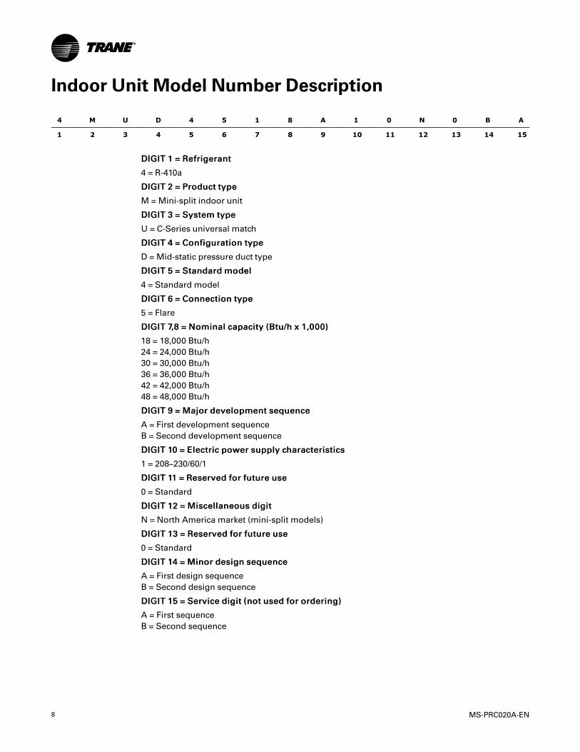
Indoor Unit Model Number Description
4 M U D 4 5 1 8 A 1 0 N 0 B A
1 2 3 4 5 6 7 8 9 10 11 12 13 14 15
DDIIGGIITT 11 == RReeffrriiggeerraanntt
4 = R-410a
DDIIGGIITT 22 == PPrroodduucctt ttyyppee
M = Mini-split indoor unit
DDIIGGIITT 33 == SSyysstteemm ttyyppee
U = C-Series universal match
DDIIGGIITT 44 == CCoonnffiigguurraattiioonn ttyyppee
D = Mid-static pressure duct type
DDIIGGIITT 55 == SSttaannddaarrdd mmooddeell
4 = Standard model
DDIIGGIITT 66 == CCoonnnneeccttiioonn ttyyppee
5 = Flare
DDIIGGIITT 77,,88 == NNoommiinnaall ccaappaacciittyy ((BBttuu//hh xx 11,,000000))
18 = 18,000 Btu/h
24 = 24,000 Btu/h
30 = 30,000 Btu/h
36 = 36,000 Btu/h
42 = 42,000 Btu/h
48 = 48,000 Btu/h
DDIIGGIITT 99 == MMaajjoorr ddeevveellooppmmeenntt sseeqquueennccee
A = First development sequence
B = Second development sequence
DDIIGGIITT 1100 == EElleeccttrriicc ppoowweerr ssuuppppllyy cchhaarraacctteerriissttiiccss
1 = 208–230/60/1
DDIIGGIITT 1111 == RReesseerrvveedd ffoorr ffuuttuurree uussee
0 = Standard
DDIIGGIITT 1122 == MMiisscceellllaanneeoouuss ddiiggiitt
N = North America market (mini-split models)
DDIIGGIITT 1133 == RReesseerrvveedd ffoorr ffuuttuurree uussee
0 = Standard
DDIIGGIITT 1144 == MMiinnoorr ddeessiiggnn sseeqquueennccee
A = First design sequence
B = Second design sequence
DDIIGGIITT 1155 == SSeerrvviiccee ddiiggiitt ((nnoott uusseedd ffoorr oorrddeerriinngg))
A = First sequence
B = Second sequence
MS-PRC020A-EN 9
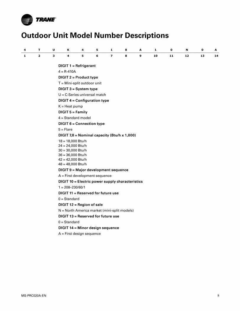
Outdoor Unit Model Number Descriptions
4 T U K 4 5 1 8 A 1 0 N 0 A
1 2 3 4 5 6 7 8 9 10 11 12 13 14
DDIIGGIITT 11 == RReeffrriiggeerraanntt
4 = R-410A
DDIIGGIITT 22 == PPrroodduucctt ttyyppee
T = Mini-split outdoor unit
DDIIGGIITT 33 == SSyysstteemm ttyyppee
U = C-Series universal match
DDIIGGIITT 44 == CCoonnffiigguurraattiioonn ttyyppee
K = Heat pump
DDIIGGIITT 55 == FFaammiillyy
4 = Standard model
DDIIGGIITT 66 == CCoonnnneeccttiioonn ttyyppee
5 = Flare
DDIIGGIITT 77,,88 == NNoommiinnaall ccaappaacciittyy ((BBttuu//hh xx 11,,000000))
18 = 18,000 Btu/h
24 = 24,000 Btu/h
30 = 30,000 Btu/h
36 = 36,000 Btu/h
42 = 42,000 Btu/h
48 = 48,000 Btu/h
DDIIGGIITT 99 == MMaajjoorr ddeevveellooppmmeenntt sseeqquueennccee
A = First development sequence
DDIIGGIITT 1100 == EElleeccttrriicc ppoowweerr ssuuppppllyy cchhaarraacctteerriissttiiccss
1 = 208–230/60/1
DDIIGGIITT 1111 == RReesseerrvveedd ffoorr ffuuttuurree uussee
0 = Standard
DDIIGGIITT 1122 == RReeggiioonn ooff ssaallee
N = North America market (mini-split models)
DDIIGGIITT 1133 == RReesseerrvveedd ffoorr ffuuttuurree uussee
0 = Standard
DDIIGGIITT 1144 == MMiinnoorr ddeessiiggnn sseeqquueennccee
A = First design sequence

10 MS-PRC020A-EN
Controls
Family Description Model Number
Zone Controllers
Wireless Remote Control
• Mode: Heat/Cool/Auto/Off
• Fan: Auto/High/Med/Low
• Service Indicator
Note: Requires the use of a DuctSignal Receiver.
TVCTRLTRDH00UT
Simple Touch Control
• Mode: Heat/Cool/Auto/Off
• Fan: Auto/High/med/Low
• Service indicator
TVCTRLTWR0002T
Wired Remote Control
• Mode: Heat/Cool/Auto/Off
• Fan: Auto/High/Med/Low
• Programmable
• Service Indicator
TVCTRLTWRWD01T
Duct Signal Receiver TVCTRLTRKA10N0
Centralized ControlSystems
VRF Central On/Off Control TVCTRLTCMA202D
VRF Touch Screen Control TVCTRLTCMA300T
Integrated SystemManagement
VRF System Controller TVCTRLTIMD00A0
VRF Enterprise ManagementSoftware
TVCTRLTSTP3P00
VRF Power Meter Interface (PIM) TVCTRLTIMB16A0
Building ManagementSystem Gateways
VRF System Controller+BACnet®
Note: This controller enablesBACnet integration.
TVCTRLTIMB17A0
Interface ModulesVRF External Contact InterfaceModule/Auxiliary Heat Module
TVCTRLTIMB14A0
Sensors VRF External Room TemperatureSensor
TVCTRLTRWTA000
Commissioning Utility Kits VRF Technician Utilities Tool (TUT) TVCTRLTIMC0300

MS-PRC020A-EN 11
Accessories
Family Description Model Number
Ball Valves
1/2 in. Ball Valve Flare BVALVE12FLARE1
1/4 in. Ball Valve Flare BVALVE14FLARE1
3/8 in. Ball Valve Flare BVALVE38FLARE1
5/8 in. Ball Valve Flare BVALVE58FLARE1
Wind Baffle
18 MBH Outdoor Unit CSERWINDBFL18AA
24, 30 MBH Outdoor Unit CSERWINDBFL24AA
36, 42, 48 30 MBH Outdoor Unit CSERWINDBFL36AA
Filter Box
18 & 24 MBH Indoor Unit MSPDUCTFLTR01AA
30,36,42,48 MBH Indoor Unit MSPDUCTFLTR02AA
12 MS-PRC020A-EN
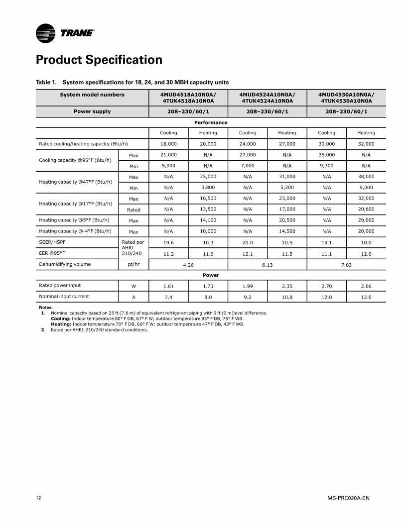
Product Specification
Table 1. System specifications for 18, 24, and 30 MBH capacity units
Systemmodel numbers 4MUD4518A10N0A/4TUK4518A10N0A
4MUD4524A10N0A/4TUK4524A10N0A
4MUD4530A10N0A/4TUK4530A10N0A
Power supply 208–230/60/1 208–230/60/1 208–230/60/1
Performance
Cooling Heating Cooling Heating Cooling Heating
Rated cooling/heating capacity (Btu/h) 18,000 20,000 24,000 27,000 30,000 32,000
Cooling capacity @95°F (Btu/h)Max 21,000 N/A 27,000 N/A 35,000 N/A
Min 5,000 N/A 7,000 N/A 9,300 N/A
Heating capacity @47°F (Btu/h)Max N/A 25,000 N/A 31,000 N/A 38,000
Min N/A 3,800 N/A 5,200 N/A 9,000
Heating capacity @17°F (Btu/h)Max N/A 16,500 N/A 23,000 N/A 32,000
Rated N/A 13,500 N/A 17,000 N/A 20,600
Heating capacity @5°F (Btu/h) Max N/A 14,100 N/A 20,500 N/A 29,000
Heating capacity @-4°F (Btu/h) Max N/A 10,000 N/A 14,500 N/A 20,000
SEER/HSPF Rated perAHRI210/240
19.6 10.3 20.0 10.5 19.1 10.0
EER @95°F 11.2 11.6 12.1 11.5 11.1 12.0
Dehumidifying volume pt/hr 4.26 6.13 7.03
Power
Rated power input W 1.61 1.73 1.99 2.35 2.70 2.66
Nominal input current A 7.4 8.0 9.2 10.8 12.0 12.0
Notes:1. Nominal capacity based on 25 ft (7.6 m) of equivalent refrigerant piping with 0 ft (0 m)level difference.
Cooling: Indoor temperature 80° F DB, 67° F W; outdoor temperature 95° F DB, 75° F WB.Heating: Indoor temperature 70° F DB, 60° F W; outdoor temperature 47° F DB, 43° F WB.
2. Rated per AHRI-210/240 standard conditions.
MS-PRC020A-EN 13
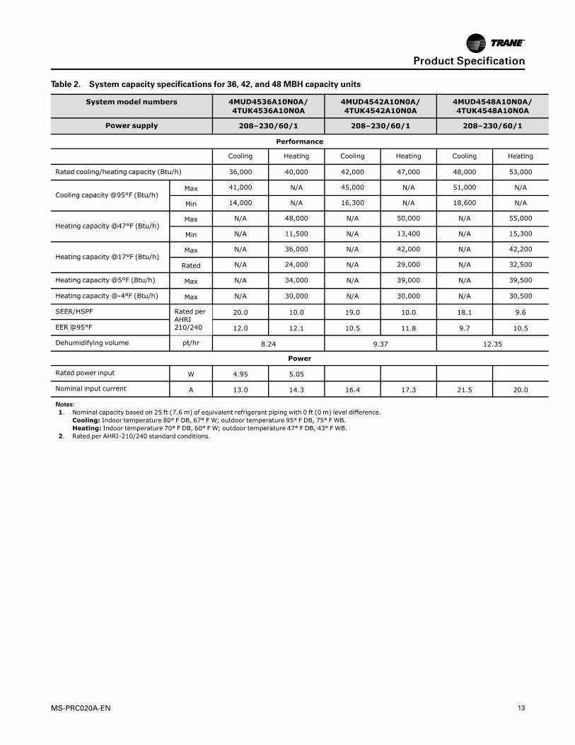
Table 2. System capacity specifications for 36, 42, and 48 MBH capacity units
Systemmodel numbers 4MUD4536A10N0A/4TUK4536A10N0A
4MUD4542A10N0A/4TUK4542A10N0A
4MUD4548A10N0A/4TUK4548A10N0A
Power supply 208–230/60/1 208–230/60/1 208–230/60/1
Performance
Cooling Heating Cooling Heating Cooling Heating
Rated cooling/heating capacity (Btu/h) 36,000 40,000 42,000 47,000 48,000 53,000
Cooling capacity @95°F (Btu/h)Max 41,000 N/A 45,000 N/A 51,000 N/A
Min 14,000 N/A 16,300 N/A 18,600 N/A
Heating capacity @47°F (Btu/h)Max N/A 48,000 N/A 50,000 N/A 55,000
Min N/A 11,500 N/A 13,400 N/A 15,300
Heating capacity @17°F (Btu/h)Max N/A 36,000 N/A 42,000 N/A 42,200
Rated N/A 24,000 N/A 29,000 N/A 32,500
Heating capacity @5°F (Btu/h) Max N/A 34,000 N/A 39,000 N/A 39,500
Heating capacity @-4°F (Btu/h) Max N/A 30,000 N/A 30,000 N/A 30,500
SEER/HSPF Rated perAHRI210/240
20.0 10.0 19.0 10.0 18.1 9.6
EER @95°F 12.0 12.1 10.5 11.8 9.7 10.5
Dehumidifying volume pt/hr 8.24 9.37 12.35
Power
Rated power input W 4.95 5.05
Nominal input current A 13.0 14.3 16.4 17.3 21.5 20.0
Notes:1. Nominal capacity based on 25 ft (7.6 m) of equivalent refrigerant piping with 0 ft (0 m) level difference.
Cooling: Indoor temperature 80° F DB, 67° F W; outdoor temperature 95° F DB, 75° F WB.Heating: Indoor temperature 70° F DB, 60° F W; outdoor temperature 47° F DB, 43° F WB.
2. Rated per AHRI-210/240 standard conditions.
PPrroodduucctt SSppeecciiffiiccaattiioonn
14 MS-PRC020A-EN
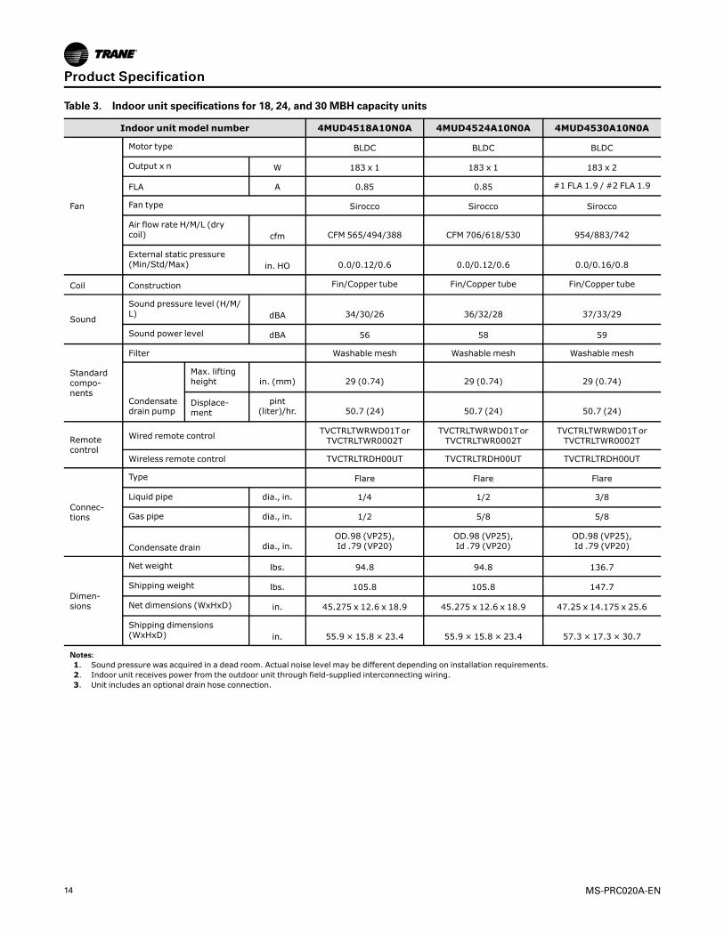
Table 3. Indoor unit specifications for 18, 24, and 30 MBH capacity units
Indoor unit model number 4MUD4518A10N0A 4MUD4524A10N0A 4MUD4530A10N0A
Fan
Motor type BLDC BLDC BLDC
Output x n W 183 x 1 183 x 1 183 x 2
FLA A 0.85 0.85 #1 FLA 1.9 / #2 FLA 1.9
Fan type Sirocco Sirocco Sirocco
Air flow rate H/M/L (drycoil) cfm CFM 565/494/388 CFM 706/618/530 954/883/742
External static pressure(Min/Std/Max) in. HO 0.0/0.12/0.6 0.0/0.12/0.6 0.0/0.16/0.8
Coil Construction Fin/Copper tube Fin/Copper tube Fin/Copper tube
Sound
Sound pressure level (H/M/L) dBA 34/30/26 36/32/28 37/33/29
Sound power level dBA 56 58 59
Standardcompo-nents
Filter Washable mesh Washable mesh Washable mesh
Condensatedrain pump
Max. liftingheight in. (mm) 29 (0.74) 29 (0.74) 29 (0.74)
Displace-ment
pint(liter)/hr. 50.7 (24) 50.7 (24) 50.7 (24)
Remotecontrol
Wired remote controlTVCTRLTWRWD01TorTVCTRLTWR0002T
TVCTRLTWRWD01TorTVCTRLTWR0002T
TVCTRLTWRWD01TorTVCTRLTWR0002T
Wireless remote control TVCTRLTRDH00UT TVCTRLTRDH00UT TVCTRLTRDH00UT
Connec-tions
Type Flare Flare Flare
Liquid pipe dia., in. 1/4 1/2 3/8
Gas pipe dia., in. 1/2 5/8 5/8
Condensate drain dia., in.OD.98 (VP25),Id .79 (VP20)
OD.98 (VP25),Id .79 (VP20)
OD.98 (VP25),Id .79 (VP20)
Dimen-sions
Net weight lbs. 94.8 94.8 136.7
Shipping weight lbs. 105.8 105.8 147.7
Net dimensions (WxHxD) in. 45.275 x 12.6 x 18.9 45.275 x 12.6 x 18.9 47.25 x 14.175 x 25.6
Shipping dimensions(WxHxD) in. 55.9 × 15.8 × 23.4 55.9 × 15.8 × 23.4 57.3 × 17.3 × 30.7
Notes:1. Sound pressure was acquired in a dead room. Actual noise level may be different depending on installation requirements.2. Indoor unit receives power from the outdoor unit through field-supplied interconnecting wiring.3. Unit includes an optional drain hose connection.
PPrroodduucctt SSppeecciiffiiccaattiioonn
MS-PRC020A-EN 15
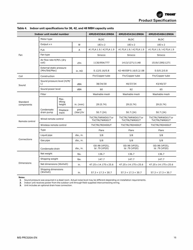
Table 4. Indoor unit specifications for 36, 42, and 48 MBH capacity units
Indoor unit model number 4MUD4536A10N0A 4MUD4542A10N0A 4MUD4548A10N0A
Fan
Motor type BLDC BLDC BLDC
Output x n W 183 x 2 183 x 2 183 x 2
FLA A #1 FLA 1.9 / #2 FLA 1.9 #1 FLA 1.9 / #2 FLA 1.9 #1 FLA 1.9 / #2 FLA 1.9
Fan type Sirocco Sirocco Sirocco
Air flow rate H/M/L (drycoil) cfm 1130/954/777 1413/1271/1148 1519/1395/1271
External static pressure(Min/Std/Max) in. HO 0.12/0.16/0.8 42-48 ESP 0.16/0.2/.08 0.0/0.2/0.8
Coil Construction Fin/Copper tube Fin/Copper tube Fin/Copper tube
Sound
Sound pressure level (H/M/L) dBA 38/34/30 40/37/34 43/40/37
Sound power level dBA 60 62 65
Standardcomponents
Filter Washable mesh Washable mesh Washable mesh
Condensatedrain pump
Max.liftingheight in. (mm) 29 (0.74) 29 (0.74) 29 (0.74)
Displace-ment
pint(liter)/hr 50.7 (24) 50.7 (24) 50.7 (24)
Remote controlWired remote control
TVCTRLTWRWD01TorTVCTRLTWR001T
TVCTRLTWRWD01TorTVCTRLTWR001T
TVCTRLTWRWD01TorTVCTRLTWR001T
Wireless remote control TVCTRLTRDH00UT TVCTRLTRDH00UT TVCTRLTRDH00UT
Connections
Type Flare Flare Flare
Liquid pipe dia., in. 3/8 3/8 3/8
Gas pipe dia., in. 5/8 5/8 5/8
Condensate drain dia., in.OD.98 (VP25),Id .79 (VP20)
OD.98 (VP25),Id .79 (VP20)
OD.98 (VP25),Id .79 (VP20)
Dimensions
Net weight lbs. 136.7 136.7 136.7
Shipping weight lbs. 147.7 147.7 147.7
Net dimensions (WxHxD) in. 47.25 x 14.175 x 25.6 47.25 x 14.175 x 25.6 47.25 x 14.175 x 25.6
Shipping dimensions(WxHxD) in. 57.3 × 17.3 × 30.7 57.3 × 17.3 × 30.7 57.3 × 17.3 × 30.7
Notes:1. Sound pressure was acquired in a dead room. Actual noise level may be different depending on installation requirements.2. Indoor unit receives power from the outdoor unit through field-supplied interconnecting wiring.3. Unit includes an optional drain hose connection.
PPrroodduucctt SSppeecciiffiiccaattiioonn

16 MS-PRC020A-EN
Table 5. Outdoor unit specifications for 18, 24, and 30 MBH capacity units
Outdoor Unit Model Number 4TUK4518A10N0A 4TUK4524A10N0A 4TUK4530A10N0A
Compressor
Type Rotary inverter Rotary inverter Rotary inverter
Oil POE POE POE
RLA A 6.1 9.0 15.1
Fan
Motor type BLDC BLDC BLDC
Output x n W 39 x 1 125 x 1 125 x 1
FLA A 0.13 0.48 0.48
Fan type Propeller Propeller Propeller
Air flow rate cfm 1550 2190 2220
ElectricalMCA A 7.7 11.7 19.3
MOP A 15.0 20.0 30.0
Coil Construction Aluminummicro channel Aluminummicro channel Aluminummicro channel
Sound
Sound pressure level(Clg/Htg) dBA 48/48 50/50 50/52
Sound power level dBA 62 65 65
Connections
Type Flare Flare Flare
Liquid pipe dia., in. 1/4 1/4 3/8
Gas pipe dia., in. 1/2 5/8 5/8
Dimensions
Net weight lbs. 99.2 142.2 154.3
Shipping weight lbs. 105.8 153.2 163.1
Net dimensions(WxHxD) in. 34.65 x 25.1 x 12.2 37.0 x 39.3 x 13.0 37.0 x 39.3 x 13.0
Shipping dimensions(WxHxD) in. 40.25 x 29.5 x 16.25 39.1875 x 43.125 x 16.75 39.1875 x 43.125 x 16.75
Refrigerant
Type R-410A R-410A R-410A
Control method EEV EEV EEV
Factory charge oz. 45.86 74.08 91.71
Additional chargeg/m 10 10 22
oz./ft 0.11 0.11 0.24
Note: Sound pressure was acquired in a dead room. Actual noise level may be different depending on installation requirements.
PPrroodduucctt SSppeecciiffiiccaattiioonn
MS-PRC020A-EN 17
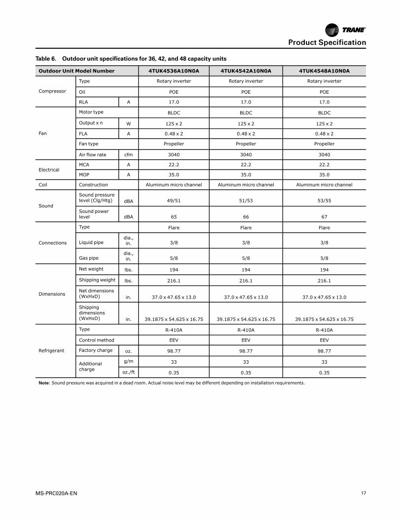
Table 6. Outdoor unit specifications for 36, 42, and 48 capacity units
Outdoor Unit Model Number 4TUK4536A10N0A 4TUK4542A10N0A 4TUK4548A10N0A
Compressor
Type Rotary inverter Rotary inverter Rotary inverter
Oil POE POE POE
RLA A 17.0 17.0 17.0
Fan
Motor type BLDC BLDC BLDC
Output x n W 125 x 2 125 x 2 125 x 2
FLA A 0.48 x 2 0.48 x 2 0.48 x 2
Fan type Propeller Propeller Propeller
Air flow rate cfm 3040 3040 3040
ElectricalMCA A 22.2 22.2 22.2
MOP A 35.0 35.0 35.0
Coil Construction Aluminummicro channel Aluminummicro channel Aluminummicro channel
Sound
Sound pressurelevel (Clg/Htg) dBA 49/51 51/53 53/55
Sound powerlevel dBA 65 66 67
Connections
Type Flare Flare Flare
Liquid pipedia.,in. 3/8 3/8 3/8
Gas pipedia.,in. 5/8 5/8 5/8
Dimensions
Net weight lbs. 194 194 194
Shipping weight lbs. 216.1 216.1 216.1
Net dimensions(WxHxD) in. 37.0 x 47.65 x 13.0 37.0 x 47.65 x 13.0 37.0 x 47.65 x 13.0
Shippingdimensions(WxHxD) in. 39.1875 x 54.625 x 16.75 39.1875 x 54.625 x 16.75 39.1875 x 54.625 x 16.75
Refrigerant
Type R-410A R-410A R-410A
Control method EEV EEV EEV
Factory charge oz. 98.77 98.77 98.77
Additionalcharge
g/m 33 33 33
oz./ft 0.35 0.35 0.35
Note: Sound pressure was acquired in a dead room. Actual noise level may be different depending on installation requirements.
PPrroodduucctt SSppeecciiffiiccaattiioonn
18 MS-PRC020A-EN
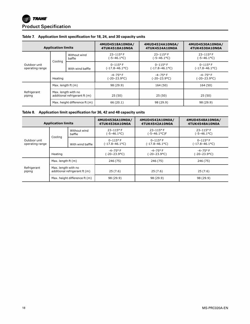
Table 7. Application limit specification for 18, 24, and 30 capacity units
Application limits4MUD4518A10N0A/4TUK4518A10N0A
4MUD4524A10N0A/4TUK4524A10N0A
4MUD4530A10N0A/4TUK4530A10N0A
Outdoor unitoperating range
Cooling
Without windbaffle
23–115° F(-5–46.1°C)
23–115° F(-5–46.1°C)
23–115° F(-5–46.1°C)
With wind baffle0–115° F
(-17.8–46.1°C)0–115° F
(-17.8–46.1°C)0–115° F
(-17.8–46.1°C)
Heating-4–75° F
(-20–23.9°C)-4–75° F
(-20–23.9°C)-4–75° F
(-20–23.9°C)
Refrigerantpiping
Max. length ft (m) 98 (29.9) 164 (50) 164 (50)
Max. length with noadditional refrigerant ft (m) 25 (50) 25 (50) 25 (50)
Max. height difference ft (m) 66 (20.1) 98 (29.9) 98 (29.9)
Table 8. Application limit specification for 36, 42 and 48 capacity units
Application limits4MUD4536A10N0A/4TUK4536A10N0A
4MUD4542A10N0A/4TUK4542A10N0A
4MUD4548A10N0A/4TUK4548A10N0A
Outdoor unitoperating range
Cooling
Without windbaffle
23–115° F(-5–46.1°C)
23–115° F(-5–46.1°C)F
23–115° F(-5–46.1°C)
With wind baffle0–115° F
(-17.8–46.1°C)0–115° F
(-17.8–46.1°C)0–115° F
(-17.8–46.1°C)
Heating-4–75° F
(-20–23.9°C)-4–75° F
(-20–23.9°C)-4–75° F
(-20–23.9°C)
Refrigerantpiping
Max. length ft (m) 246 (75) 246 (75) 246 (75)
Max. length with noadditional refrigerant ft (m) 25 (7.6) 25 (7.6) 25 (7.6)
Max. height difference ft (m) 98 (29.9) 98 (29.9) 98 (29.9)
PPrroodduucctt SSppeecciiffiiccaattiioonn

MS-PRC020A-EN 19
Capacity Tables
Table 9. Capacity table for 4MUD4518A10N0A and 4TUK4518A10N0A (68°F, 73°F, 79°F, and 80°F): cooling
Outdoor AirTemp.(°F DB)
Indoor Temperature (°F)
68 (20.0°C, DB) 73 (22.8°C, DB) 79 (26.1°C, DB) 80 (26.7°C, DB)
57 (13.9°C,WB) 61 (19.4°C, WB) 64 (17.8°C, WB) 67 (19.4°C,WB)
TC(Btu/h)
SHC(Btu/h)
TC(Btu/h)
SHC(Btu/h)
TC(Btu/h)
SHC(Btu/h)
TC(Btu/h)
SHC(Btu/h)
0 19.7 15.7 20.2 16.1 20.7 16.6 21.1 16.9
10 19.9 15.9 20.4 16.3 20.9 16.8 21.3 17.1
20 20.1 16.1 20.6 16.5 21.2 16.9 21.6 17.2
30 20.3 16.2 20.8 16.7 21.4 17.1 21.8 17.4
40 20.5 16.4 21.1 16.8 21.6 17.3 22.0 17.6
50 20.7 16.6 21.3 17.0 21.8 17.5 22.2 17.8
54 20.8 16.6 21.4 17.1 21.9 17.5 22.3 17.9
58 20.9 16.7 21.4 17.2 22.0 17.6 22.4 17.9
60 20.9 16.7 21.5 17.2 22.1 17.7 22.5 18.0
64 21.0 16.8 21.6 17.3 22.2 17.7 22.6 18.1
67 21.1 16.9 21.6 17.3 22.2 17.8 22.6 18.1
70 21.1 16.9 21.7 17.4 22.3 17.8 22.7 18.2
73 20.6 16.5 21.2 16.9 21.7 17.4 22.1 17.7
77 19.9 15.9 20.5 16.4 21.0 16.8 21.4 17.1
80 19.4 15.5 19.9 15.9 20.4 16.4 20.8 16.7
84 18.7 15.0 19.2 15.4 19.7 15.8 20.1 16.1
88 18.0 14.4 18.5 14.8 19.0 15.2 19.3 15.5
92 17.3 13.8 17.8 14.2 18.2 14.6 18.6 14.9
95 16.8 13.4 17.2 13.8 17.7 14.1 18.0 14.4
99 16.3 13.0 16.7 13.4 17.2 13.7 17.5 14.0
103 15.8 12.7 16.3 13.0 16.7 13.4 17.0 13.6
107 15.4 12.3 15.8 12.6 16.2 13.0 16.5 13.2
111 14.9 11.9 15.3 12.2 15.7 12.6 16.0 12.8
115 14.4 11.6 14.8 11.9 15.2 12.2 15.5 12.4
Notes:1. Capacity index: Total capacity (TC) = 18 MBh; sensible heat capacity (SHC) = 14.4 MBh.2. Indoor air temperatures (F° DB/WB) in cooling mode: 68/57, 72/61, 77/64, 80/67, 86/72, 90/75.3. Refrigerant piping length: 16.4 ft (5 m)4. Level difference : 0 ft (0 m)

20 MS-PRC020A-EN
Table 10. Capacity table for 4MUD4518A10N0A and 4TUK4518A10N0A (85°F, 87°F, and 89°F): cooling
Outdoor AirTemp.(°F DB)
Indoor Temperature (°F)
85 (29.4°C , DB) 87 (30.6°C, DB) 89 (31.7°C, DB)
70 (21.1°C, WB) 72 (22.2°C, WB) 75 (23.9°C, WB)
TC(Btu/h)
SHC(Btu/h)
TC(Btu/h)
SHC(Btu/h)
TC(Btu/h)
SHC(Btu/h)
0 21.6 17.3 22.0 17.6 22.1 17.7
10 21.9 17.5 22.2 17.8 22.4 17.9
20 22.1 17.7 22.4 17.9 22.6 18.1
30 22.3 17.9 22.7 18.1 22.8 18.3
40 22.6 18.1 22.9 18.3 23.1 18.5
50 22.8 18.2 23.1 18.5 23.3 18.7
54 22.9 18.3 23.2 18.6 23.4 18.7
58 23.0 18.4 23.3 18.7 23.5 18.8
60 23.0 18.4 23.4 18.7 23.6 18.9
64 23.1 18.5 23.5 18.8 23.7 18.9
67 23.2 18.6 23.5 18.8 23.7 19.0
70 23.3 18.6 23.6 18.9 23.8 19.0
73 22.7 18.2 23.0 18.4 23.2 18.6
77 21.9 17.5 22.2 17.8 22.4 17.9
80 21.3 17.1 21.7 17.3 21.8 17.5
84 20.6 16.5 20.9 16.7 21.0 16.8
88 19.8 15.8 20.1 16.1 20.3 16.2
92 19.0 15.2 19.3 15.5 19.5 15.6
95 18.5 14.8 18.7 15.0 18.9 15.1
99 17.9 14.4 18.2 14.6 18.4 14.7
103 17.4 13.9 17.7 14.1 17.8 14.3
107 16.9 13.5 17.2 13.7 17.3 13.8
111 16.4 13.1 16.6 13.3 16.8 13.4
115 15.9 12.7 16.1 12.9 16.3 13.0
Notes:1. Capacity index: Total capacity (TC) = 18 MBh; sensible heat capacity (SHC) = 14.4 MBh.2. Indoor air temperatures (F° DB/WB) in cooling mode: 68/57, 72/61, 77/64, 80/67, 86/72, 90/75.3. Refrigerant piping length: 16.4 ft (5 m)4. Level difference : 0 ft (0 m)
CCaappaacciittyy TTaabblleess
MS-PRC020A-EN 21
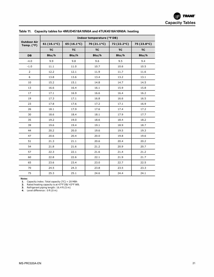
Table 11. Capacity tables for 4MUD4518A10N0A and 4TUK4518A10N0A: heating
Outdoor AirTemp. (°F)
Indoor temperature (°F DB)
61 (16.1°C) 65 (16.1°C) 70 (21.1°C) 72 (22.2°C) 75 (23.8°C)
TC TC TC TC TC
DB Btu/h Btu/h Btu/h Btu/h Btu/h
-4.0 9.9 9.8 9.6 9.5 9.4
-1.0 11.1 11.0 10.7 10.6 10.5
2 12.2 12.1 11.9 11.7 11.6
6 13.8 13.6 13.4 13.2 13.1
10 15.2 15.1 14.8 14.7 14.5
13 16.6 16.4 16.1 15.9 15.8
17 17.1 16.9 16.6 16.4 16.2
19 17.3 17.1 16.8 16.6 16.5
23 17.8 17.6 17.2 17.1 16.9
26 18.1 17.9 17.6 17.4 17.2
30 18.6 18.4 18.1 17.9 17.7
35 19.2 19.0 18.6 18.4 18.2
39 19.6 19.4 19.1 18.9 18.7
44 20.2 20.0 19.6 19.5 19.3
47 20.6 20.4 20.0 19.8 19.6
51 21.3 21.1 20.6 20.4 20.2
54 21.8 21.6 21.2 20.9 20.7
57 22.3 22.1 21.6 21.4 21.2
60 22.8 22.6 22.1 21.9 21.7
65 23.6 23.4 23.0 22.7 22.5
70 24.5 24.3 23.8 23.5 23.3
75 25.3 25.1 24.6 24.4 24.1
Notes:1. Capacity index: Total capacity (TC) = 20 MBh2. Rated heating capacity is at 47°F DB/ 43°F WB.3. Refrigerant piping length: 16.4 ft (5 m)4. Level difference : 0 ft (0 m)
CCaappaacciittyy TTaabblleess
22 MS-PRC020A-EN
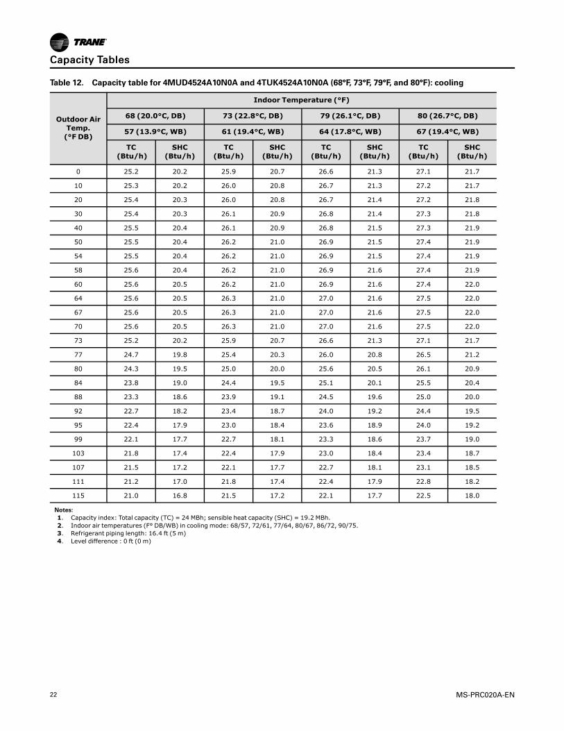
Table 12. Capacity table for 4MUD4524A10N0A and 4TUK4524A10N0A (68°F, 73°F, 79°F, and 80°F): cooling
Outdoor AirTemp.(°F DB)
Indoor Temperature (°F)
68 (20.0°C, DB) 73 (22.8°C, DB) 79 (26.1°C, DB) 80 (26.7°C, DB)
57 (13.9°C, WB) 61 (19.4°C, WB) 64 (17.8°C, WB) 67 (19.4°C,WB)
TC(Btu/h)
SHC(Btu/h)
TC(Btu/h)
SHC(Btu/h)
TC(Btu/h)
SHC(Btu/h)
TC(Btu/h)
SHC(Btu/h)
0 25.2 20.2 25.9 20.7 26.6 21.3 27.1 21.7
10 25.3 20.2 26.0 20.8 26.7 21.3 27.2 21.7
20 25.4 20.3 26.0 20.8 26.7 21.4 27.2 21.8
30 25.4 20.3 26.1 20.9 26.8 21.4 27.3 21.8
40 25.5 20.4 26.1 20.9 26.8 21.5 27.3 21.9
50 25.5 20.4 26.2 21.0 26.9 21.5 27.4 21.9
54 25.5 20.4 26.2 21.0 26.9 21.5 27.4 21.9
58 25.6 20.4 26.2 21.0 26.9 21.6 27.4 21.9
60 25.6 20.5 26.2 21.0 26.9 21.6 27.4 22.0
64 25.6 20.5 26.3 21.0 27.0 21.6 27.5 22.0
67 25.6 20.5 26.3 21.0 27.0 21.6 27.5 22.0
70 25.6 20.5 26.3 21.0 27.0 21.6 27.5 22.0
73 25.2 20.2 25.9 20.7 26.6 21.3 27.1 21.7
77 24.7 19.8 25.4 20.3 26.0 20.8 26.5 21.2
80 24.3 19.5 25.0 20.0 25.6 20.5 26.1 20.9
84 23.8 19.0 24.4 19.5 25.1 20.1 25.5 20.4
88 23.3 18.6 23.9 19.1 24.5 19.6 25.0 20.0
92 22.7 18.2 23.4 18.7 24.0 19.2 24.4 19.5
95 22.4 17.9 23.0 18.4 23.6 18.9 24.0 19.2
99 22.1 17.7 22.7 18.1 23.3 18.6 23.7 19.0
103 21.8 17.4 22.4 17.9 23.0 18.4 23.4 18.7
107 21.5 17.2 22.1 17.7 22.7 18.1 23.1 18.5
111 21.2 17.0 21.8 17.4 22.4 17.9 22.8 18.2
115 21.0 16.8 21.5 17.2 22.1 17.7 22.5 18.0
Notes:1. Capacity index: Total capacity (TC) = 24 MBh; sensible heat capacity (SHC) = 19.2 MBh.2. Indoor air temperatures (F° DB/WB) in cooling mode: 68/57, 72/61, 77/64, 80/67, 86/72, 90/75.3. Refrigerant piping length: 16.4 ft (5 m)4. Level difference : 0 ft (0 m)
CCaappaacciittyy TTaabblleess
MS-PRC020A-EN 23
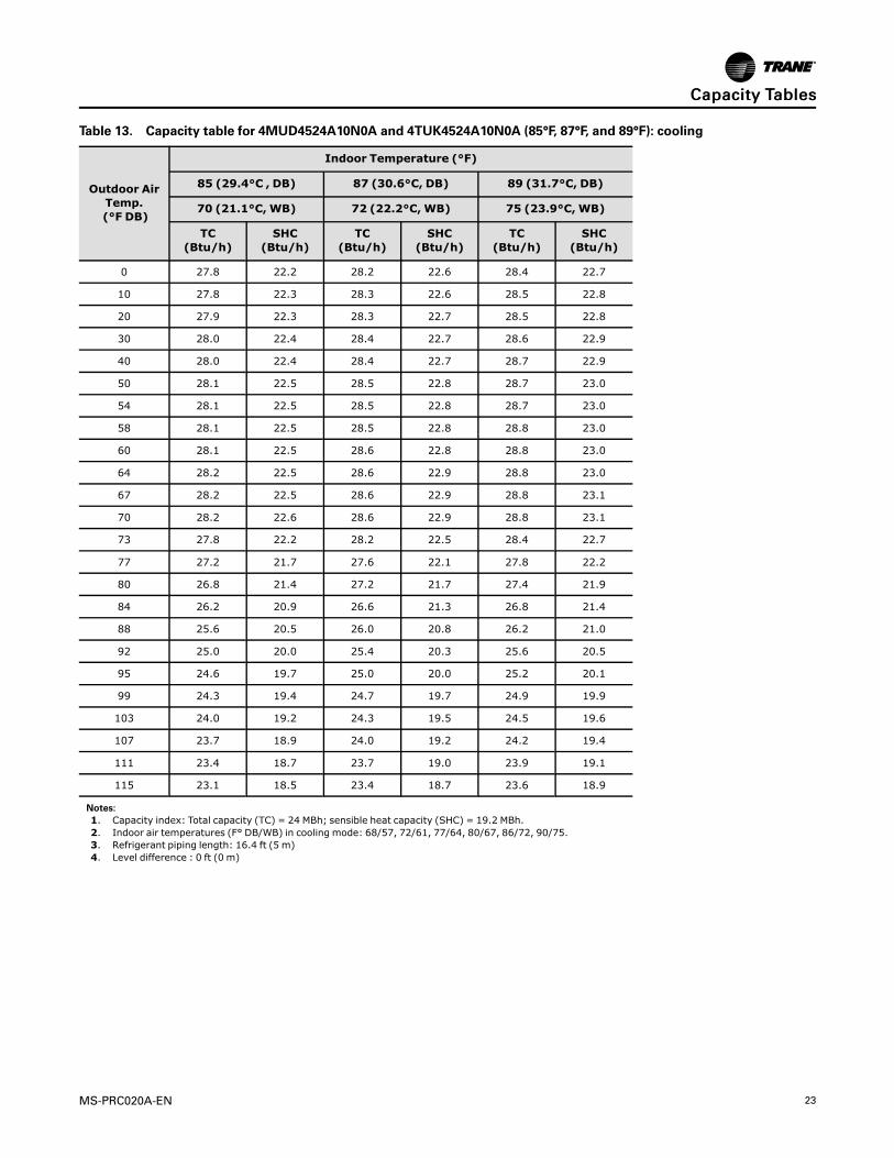
Table 13. Capacity table for 4MUD4524A10N0A and 4TUK4524A10N0A (85°F, 87°F, and 89°F): cooling
Outdoor AirTemp.(°F DB)
Indoor Temperature (°F)
85 (29.4°C , DB) 87 (30.6°C, DB) 89 (31.7°C, DB)
70 (21.1°C, WB) 72 (22.2°C, WB) 75 (23.9°C, WB)
TC(Btu/h)
SHC(Btu/h)
TC(Btu/h)
SHC(Btu/h)
TC(Btu/h)
SHC(Btu/h)
0 27.8 22.2 28.2 22.6 28.4 22.7
10 27.8 22.3 28.3 22.6 28.5 22.8
20 27.9 22.3 28.3 22.7 28.5 22.8
30 28.0 22.4 28.4 22.7 28.6 22.9
40 28.0 22.4 28.4 22.7 28.7 22.9
50 28.1 22.5 28.5 22.8 28.7 23.0
54 28.1 22.5 28.5 22.8 28.7 23.0
58 28.1 22.5 28.5 22.8 28.8 23.0
60 28.1 22.5 28.6 22.8 28.8 23.0
64 28.2 22.5 28.6 22.9 28.8 23.0
67 28.2 22.5 28.6 22.9 28.8 23.1
70 28.2 22.6 28.6 22.9 28.8 23.1
73 27.8 22.2 28.2 22.5 28.4 22.7
77 27.2 21.7 27.6 22.1 27.8 22.2
80 26.8 21.4 27.2 21.7 27.4 21.9
84 26.2 20.9 26.6 21.3 26.8 21.4
88 25.6 20.5 26.0 20.8 26.2 21.0
92 25.0 20.0 25.4 20.3 25.6 20.5
95 24.6 19.7 25.0 20.0 25.2 20.1
99 24.3 19.4 24.7 19.7 24.9 19.9
103 24.0 19.2 24.3 19.5 24.5 19.6
107 23.7 18.9 24.0 19.2 24.2 19.4
111 23.4 18.7 23.7 19.0 23.9 19.1
115 23.1 18.5 23.4 18.7 23.6 18.9
Notes:1. Capacity index: Total capacity (TC) = 24 MBh; sensible heat capacity (SHC) = 19.2 MBh.2. Indoor air temperatures (F° DB/WB) in cooling mode: 68/57, 72/61, 77/64, 80/67, 86/72, 90/75.3. Refrigerant piping length: 16.4 ft (5 m)4. Level difference : 0 ft (0 m)
CCaappaacciittyy TTaabblleess

24 MS-PRC020A-EN
Table 14. Capacity tables for 4MUD4524A10N0A and 4TUK4524A10N0A: heating
Outdoor AirTemp. (°F)
Indoor temperature (°F DB)
61 (16.1°C) 65 (16.1°C) 70 (21.1°C) 72 (22.2°C) 75 (23.8°C)
TC TC TC TC TC
DB Btu/h Btu/h Btu/h Btu/h Btu/h
-4.0 14.9 14.8 14.5 14.4 14.2
-1.0 15.9 15.8 15.5 15.3 15.2
2 16.9 16.8 16.4 16.3 16.1
6 18.3 18.1 17.7 17.6 17.4
10 19.5 19.4 19.0 18.8 18.6
13 20.7 20.5 20.1 19.9 19.7
17 21.5 21.3 20.9 20.7 20.5
19 22.0 21.7 21.3 21.1 20.9
23 22.8 22.6 22.1 21.9 21.7
26 23.4 23.2 22.7 22.5 22.3
30 24.3 24.0 23.6 23.3 23.1
35 25.3 25.0 24.5 24.3 24.1
39 26.1 25.9 25.3 25.1 24.8
44 27.2 26.9 26.4 26.1 25.9
47 27.8 27.5 27.0 26.7 26.5
51 29.0 28.7 28.2 27.9 27.6
54 30.0 29.7 29.1 28.8 28.5
57 30.9 30.6 30.0 29.7 29.4
60 31.8 31.5 30.9 30.6 30.3
65 33.4 33.1 32.4 32.1 31.8
70 34.9 34.6 33.9 33.6 33.2
75 36.5 36.1 35.4 35.0 34.7
Notes:1. Capacity index: Total capacity (TC) = 27 MBh.2. Rated heating capacity is at 47°F DB/ 43°F WB.3. Refrigerant piping length: 16.4 ft (5 m)4. Level difference : 0 ft (0 m)
CCaappaacciittyy TTaabblleess
MS-PRC020A-EN 25
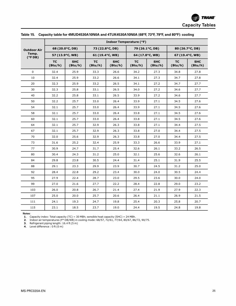
Table 15. Capacity table for 4MUD4530A10N0A and 4TUK4530A10N0A (68°F, 73°F, 79°F, and 80°F): cooling
Outdoor AirTemp.(°F DB)
Indoor Temperature (°F)
68 (20.0°C, DB) 73 (22.8°C, DB) 79 (26.1°C, DB) 80 (26.7°C, DB)
57 (13.9°C, WB) 61 (19.4°C, WB) 64 (17.8°C, WB) 67 (19.4°C,WB)
TC(Btu/h)
SHC(Btu/h)
TC(Btu/h)
SHC(Btu/h)
TC(Btu/h)
SHC(Btu/h)
TC(Btu/h)
SHC(Btu/h)
0 32.4 25.9 33.3 26.6 34.2 27.3 34.8 27.8
10 32.4 25.9 33.2 26.6 34.1 27.3 34.7 27.8
20 32.3 25.9 33.2 26.5 34.1 27.2 34.7 27.7
30 32.3 25.8 33.1 26.5 34.0 27.2 34.6 27.7
40 32.2 25.8 33.1 26.5 33.9 27.2 34.6 27.7
50 32.2 25.7 33.0 26.4 33.9 27.1 34.5 27.6
54 32.1 25.7 33.0 26.4 33.9 27.1 34.5 27.6
58 32.1 25.7 33.0 26.4 33.8 27.1 34.5 27.6
60 32.1 25.7 33.0 26.4 33.8 27.1 34.5 27.6
64 32.1 25.7 32.9 26.3 33.8 27.1 34.4 27.5
67 32.1 25.7 32.9 26.3 33.8 27.0 34.4 27.5
70 32.0 25.6 32.9 26.3 33.8 27.0 34.4 27.5
73 31.6 25.2 32.4 25.9 33.3 26.6 33.9 27.1
77 30.9 24.7 31.7 25.4 32.6 26.1 33.2 26.5
80 30.4 24.3 31.2 25.0 32.1 25.6 32.6 26.1
84 29.8 23.8 30.5 24.4 31.4 25.1 31.9 25.5
88 29.1 23.3 29.9 23.9 30.7 24.5 31.2 25.0
92 28.4 22.8 29.2 23.4 30.0 24.0 30.5 24.4
95 27.9 22.4 28.7 23.0 29.5 23.6 30.0 24.0
99 27.0 21.6 27.7 22.2 28.4 22.8 29.0 23.2
103 26.0 20.8 26.7 21.4 27.4 21.9 27.9 22.3
107 25.0 20.0 25.7 20.6 26.4 21.1 26.9 21.5
111 24.1 19.3 24.7 19.8 25.4 20.3 25.8 20.7
115 23.1 18.5 23.7 19.0 24.4 19.5 24.8 19.8
Notes:1. Capacity index: Total capacity (TC) = 30 MBh; sensible heat capacity (SHC) = 24 MBh.2. Indoor air temperatures (F° DB/WB) in cooling mode: 68/57, 72/61, 77/64, 80/67, 86/72, 90/75.3. Refrigerant piping length: 16.4 ft (5 m)4. Level difference : 0 ft (0 m)
CCaappaacciittyy TTaabblleess

26 MS-PRC020A-EN
Table 16. Capacity table for 4MUD4530A10N0A and 4TUK4530A10N0A (85°F, 87°F, and 89°F): cooling
Outdoor AirTemp.(°F DB)
Indoor Temperature (°F)
85 (29.4°C , DB) 87 (30.6°C, DB) 89 (31.7°C, DB)
70 (21.1°C, WB) 72 (22.2°C, WB) 75 (23.9°C,WB)
TC(Btu/h)
SHC(Btu/h)
TC(Btu/h)
SHC(Btu/h)
TC(Btu/h)
SHC(Btu/h)
0 35.7 28.5 36.2 29.0 36.5 29.2
10 35.6 28.5 36.1 28.9 36.4 29.1
20 35.6 28.4 36.1 28.9 36.4 29.1
30 35.5 28.4 36.0 28.8 36.3 29.1
40 35.4 28.3 36.0 28.8 36.3 29.0
50 35.4 28.3 35.9 28.7 36.2 29.0
54 35.4 28.3 35.9 28.7 36.2 28.9
58 35.3 28.3 35.9 28.7 36.1 28.9
60 35.3 28.3 35.8 28.7 36.1 28.9
64 35.3 28.2 35.8 28.7 36.1 28.9
67 35.3 28.2 35.8 28.6 36.1 28.9
70 35.3 28.2 35.8 28.6 36.1 28.9
73 34.7 27.8 35.2 28.2 35.5 28.4
77 34.0 27.2 34.5 27.6 34.8 27.8
80 33.5 26.8 34.0 27.2 34.2 27.4
84 32.7 26.2 33.2 26.6 33.5 26.8
88 32.0 25.6 32.5 26.0 32.8 26.2
92 31.3 25.0 31.8 25.4 32.0 25.6
95 30.8 24.6 31.2 25.0 31.5 25.2
99 29.7 23.7 30.1 24.1 30.4 24.3
103 28.6 22.9 29.0 23.2 29.3 23.4
107 27.6 22.0 28.0 22.4 28.2 22.6
111 26.5 21.2 26.9 21.5 27.1 21.7
115 25.4 20.3 25.8 20.6 26.0 20.8
Notes:1. Capacity index: Total capacity (TC) = 30 MBh; sensible heat capacity (SHC) = 24 MBh.2. Indoor air temperatures (F° DB/WB) in cooling mode: 68/57, 72/61, 77/64, 80/67, 86/72, 90/75.3. Refrigerant piping length: 16.4 ft (5 m)4. Level difference : 0 ft (0 m)
CCaappaacciittyy TTaabblleess

MS-PRC020A-EN 27
Table 17. Capacity tables for 4MUD4530A10N0A and 4TUK4530A10N0A: heating
Outdoor AirTemp. (°F)
Indoor temperature (°F DB)
61 (16.1°C) 65 (16.1°C) 70 (21.1°C) 72 (22.2°C) 75 (23.8°C)
TC TC TC TC TC
DB Btu/h Btu/h Btu/h Btu/h Btu/h
-4.0 19.8 19.6 19.2 19.0 18.8
-1.0 20.6 20.4 20.0 19.8 19.6
2 21.3 21.1 20.7 20.5 20.3
6 22.3 22.1 21.7 21.5 21.3
10 23.3 23.1 22.6 22.4 22.2
13 35.1 34.8 34.1 33.8 33.4
17 34.9 34.5 33.9 33.5 33.2
19 34.7 34.4 33.7 33.4 33.1
23 34.5 34.2 33.5 33.2 32.8
26 34.3 34.0 33.3 33.0 32.6
30 34.0 33.7 33.1 32.7 32.4
35 33.7 33.4 32.7 32.4 32.1
39 33.5 33.2 32.5 32.2 31.9
44 33.2 32.8 32.2 31.9 31.5
47 33.0 32.6 32.0 31.7 31.4
51 34.4 34.1 33.4 33.1 32.7
54 35.5 35.2 34.5 34.2 33.8
57 36.6 36.2 35.5 35.2 34.8
60 37.7 37.4 36.6 36.3 35.9
65 39.6 39.2 38.4 38.1 37.7
70 41.4 41.0 40.2 39.8 39.4
75 43.3 42.8 42.0 41.6 41.2
Notes:1. Capacity index: Total capacity (TC) = 32 MBh2. Rated heating capacity is at 47°F DB/ 43°F WB.3. Refrigerant piping length: 16.4 ft (5 m)4. Level difference : 0 ft (0 m)
CCaappaacciittyy TTaabblleess
28 MS-PRC020A-EN
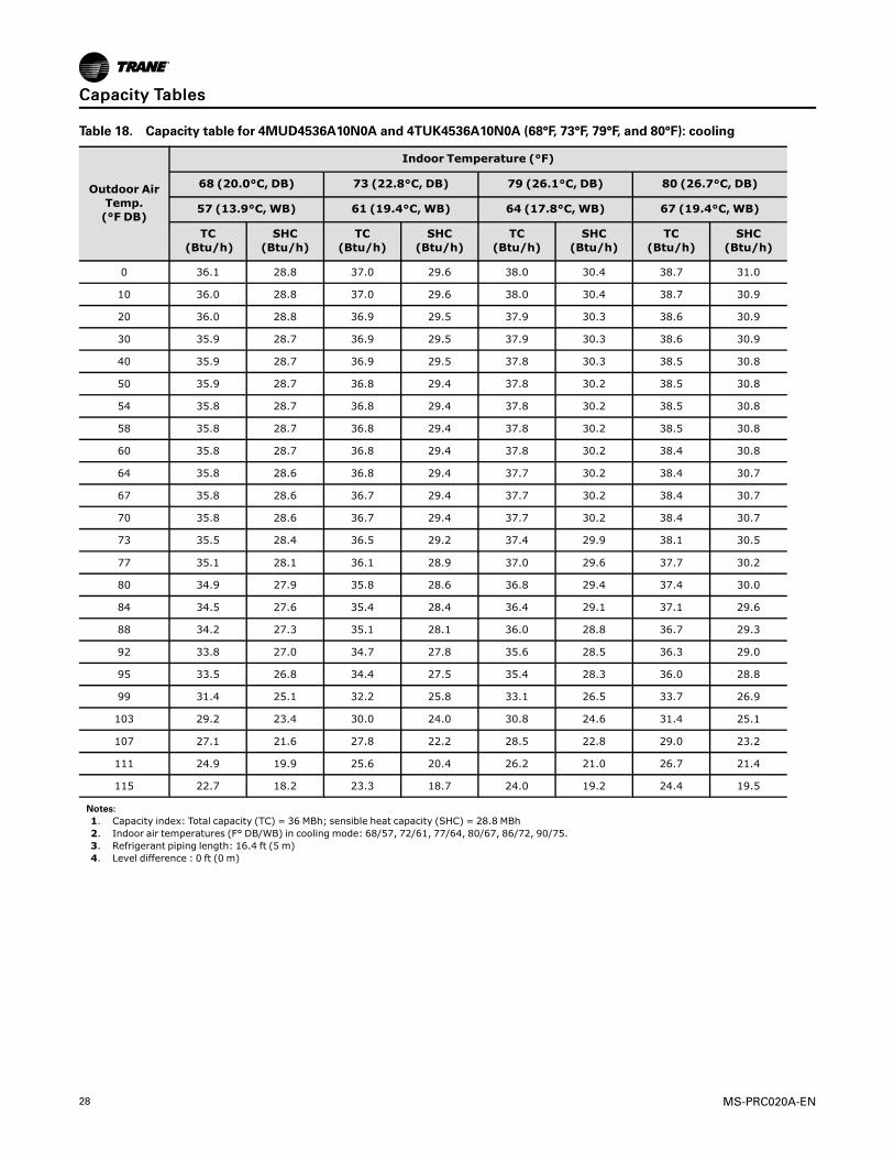
Table 18. Capacity table for 4MUD4536A10N0A and 4TUK4536A10N0A (68°F, 73°F, 79°F, and 80°F): cooling
Outdoor AirTemp.(°F DB)
Indoor Temperature (°F)
68 (20.0°C, DB) 73 (22.8°C, DB) 79 (26.1°C, DB) 80 (26.7°C, DB)
57 (13.9°C, WB) 61 (19.4°C, WB) 64 (17.8°C, WB) 67 (19.4°C,WB)
TC(Btu/h)
SHC(Btu/h)
TC(Btu/h)
SHC(Btu/h)
TC(Btu/h)
SHC(Btu/h)
TC(Btu/h)
SHC(Btu/h)
0 36.1 28.8 37.0 29.6 38.0 30.4 38.7 31.0
10 36.0 28.8 37.0 29.6 38.0 30.4 38.7 30.9
20 36.0 28.8 36.9 29.5 37.9 30.3 38.6 30.9
30 35.9 28.7 36.9 29.5 37.9 30.3 38.6 30.9
40 35.9 28.7 36.9 29.5 37.8 30.3 38.5 30.8
50 35.9 28.7 36.8 29.4 37.8 30.2 38.5 30.8
54 35.8 28.7 36.8 29.4 37.8 30.2 38.5 30.8
58 35.8 28.7 36.8 29.4 37.8 30.2 38.5 30.8
60 35.8 28.7 36.8 29.4 37.8 30.2 38.4 30.8
64 35.8 28.6 36.8 29.4 37.7 30.2 38.4 30.7
67 35.8 28.6 36.7 29.4 37.7 30.2 38.4 30.7
70 35.8 28.6 36.7 29.4 37.7 30.2 38.4 30.7
73 35.5 28.4 36.5 29.2 37.4 29.9 38.1 30.5
77 35.1 28.1 36.1 28.9 37.0 29.6 37.7 30.2
80 34.9 27.9 35.8 28.6 36.8 29.4 37.4 30.0
84 34.5 27.6 35.4 28.4 36.4 29.1 37.1 29.6
88 34.2 27.3 35.1 28.1 36.0 28.8 36.7 29.3
92 33.8 27.0 34.7 27.8 35.6 28.5 36.3 29.0
95 33.5 26.8 34.4 27.5 35.4 28.3 36.0 28.8
99 31.4 25.1 32.2 25.8 33.1 26.5 33.7 26.9
103 29.2 23.4 30.0 24.0 30.8 24.6 31.4 25.1
107 27.1 21.6 27.8 22.2 28.5 22.8 29.0 23.2
111 24.9 19.9 25.6 20.4 26.2 21.0 26.7 21.4
115 22.7 18.2 23.3 18.7 24.0 19.2 24.4 19.5
Notes:1. Capacity index: Total capacity (TC) = 36 MBh; sensible heat capacity (SHC) = 28.8 MBh2. Indoor air temperatures (F° DB/WB) in cooling mode: 68/57, 72/61, 77/64, 80/67, 86/72, 90/75.3. Refrigerant piping length: 16.4 ft (5 m)4. Level difference : 0 ft (0 m)
CCaappaacciittyy TTaabblleess

MS-PRC020A-EN 29
Table 19. Capacity table for 4MUD4536A10N0A and 4TUK4536A10N0A (85°F, 87°F, and 89°F): cooling
Outdoor AirTemp.(°F DB)
Indoor Temperature (°F)
85 (29.4°C , DB) 87 (30.6°C, DB) 89 (31.7°C, DB)
70 (21.1°C, WB) 72 (22.2°C, WB) 75 (23.9°C, WB)
TC(Btu/h)
SHC(Btu/h)
TC(Btu/h)
SHC(Btu/h)
TC(Btu/h)
SHC(Btu/h)
0 39.7 31.7 40.3 32.2 40.6 32.5
10 39.6 31.7 40.2 32.2 40.5 32.4
20 39.6 31.7 40.2 32.1 40.5 32.4
30 39.5 31.6 40.1 32.1 40.4 32.4
40 39.5 31.6 40.1 32.1 40.4 32.3
50 39.4 31.6 40.0 32.0 40.4 32.3
54 39.4 31.5 40.0 32.0 40.3 32.3
58 39.4 31.5 40.0 32.0 40.3 32.3
60 39.4 31.5 40.0 32.0 40.3 32.3
64 39.4 31.5 40.0 32.0 40.3 32.2
67 39.4 31.5 40.0 32.0 40.3 32.2
70 39.4 31.5 40.0 32.0 40.3 32.2
73 39.1 31.3 39.7 31.7 40.0 32.0
77 38.7 30.9 39.3 31.4 39.6 31.7
80 38.4 30.7 39.0 31.2 39.3 31.4
84 38.0 30.4 38.6 30.8 38.9 31.1
88 37.6 30.1 38.2 30.5 38.5 30.8
92 37.2 29.8 37.8 30.2 38.1 30.4
95 36.9 29.5 37.5 30.0 37.8 30.2
99 34.5 27.6 35.0 28.0 35.3 28.3
103 32.1 25.7 32.6 26.1 32.9 26.3
107 29.8 23.8 30.2 24.2 30.5 24.4
111 27.4 21.9 27.8 22.2 28.0 22.4
115 25.0 20.0 25.4 20.3 25.6 20.5
Notes:1. Capacity index: Total capacity (TC) = 36 MBh; sensible heat capacity (SHC) = 28.8 MBh2. Indoor air temperatures (F° DB/WB) in cooling mode: 68/57, 72/61, 77/64, 80/67, 86/72, 90/75.3. Refrigerant piping length: 16.4 ft (5 m)4. Level difference : 0 ft (0 m)
CCaappaacciittyy TTaabblleess

30 MS-PRC020A-EN
Table 20. Capacity tables for 4MUD4536A10N0A and 4TUK4536A10N0A: heating
Outdoor AirTemp. (°F)
Indoor temperature (°F DB)
61 (16.1°C) 65 (16.1°C) 70 (21.1°C) 72 (22.2°C) 75 (23.8°C)
TC TC TC TC TC
DB Btu/h Btu/h Btu/h Btu/h Btu/h
-4.0 30.5 30.2 29.6 29.3 29.0
-1.0 31.8 31.5 30.9 30.6 30.2
2 33.1 32.7 32.1 31.8 31.5
6 34.8 34.4 33.8 33.4 33.1
10 36.4 36.1 35.4 35.0 34.7
13 37.9 37.5 36.8 36.4 36.1
17 38.3 37.9 37.2 36.8 36.4
19 38.5 38.1 37.4 37.0 36.6
23 38.9 38.5 37.7 37.4 37.0
26 39.2 38.8 38.0 37.6 37.3
30 39.6 39.2 38.4 38.0 37.6
35 40.0 39.6 38.9 38.5 38.1
39 40.4 40.0 39.2 38.8 38.5
44 40.9 40.5 39.7 39.3 38.9
47 41.2 40.8 40.0 39.6 39.2
51 42.3 41.9 41.1 40.7 40.3
54 43.2 42.8 42.0 41.5 41.1
57 44.0 43.6 42.8 42.3 41.9
60 44.9 44.5 43.6 43.2 42.7
65 46.4 45.9 45.0 44.6 44.1
70 47.8 47.3 46.4 45.9 45.5
75 49.2 48.8 47.8 47.3 46.8
Notes:1. Capacity index: Total capacity (TC) = 40 MBh2. Rated heating capacity is at 47°F DB/ 43°F WB.3. Refrigerant piping length: 16.4 ft (5 m)4. Level difference : 0 ft (0 m)
CCaappaacciittyy TTaabblleess
MS-PRC020A-EN 31
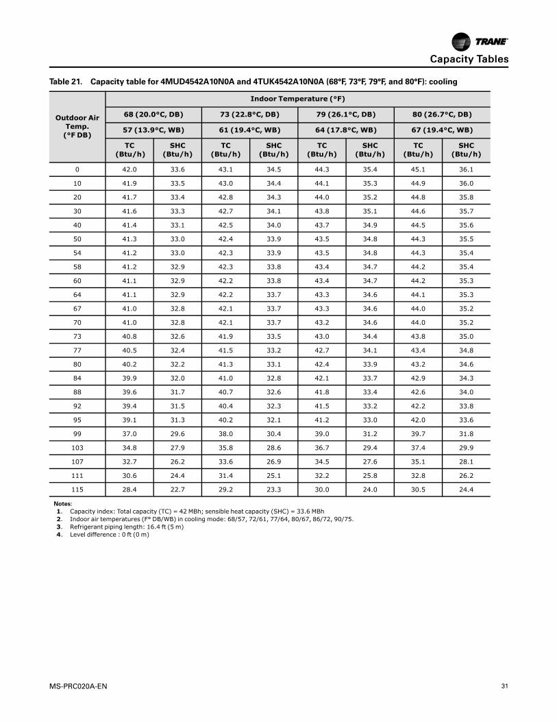
Table 21. Capacity table for 4MUD4542A10N0A and 4TUK4542A10N0A (68°F, 73°F, 79°F, and 80°F): cooling
Outdoor AirTemp.(°F DB)
Indoor Temperature (°F)
68 (20.0°C, DB) 73 (22.8°C, DB) 79 (26.1°C, DB) 80 (26.7°C, DB)
57 (13.9°C, WB) 61 (19.4°C, WB) 64 (17.8°C, WB) 67 (19.4°C,WB)
TC(Btu/h)
SHC(Btu/h)
TC(Btu/h)
SHC(Btu/h)
TC(Btu/h)
SHC(Btu/h)
TC(Btu/h)
SHC(Btu/h)
0 42.0 33.6 43.1 34.5 44.3 35.4 45.1 36.1
10 41.9 33.5 43.0 34.4 44.1 35.3 44.9 36.0
20 41.7 33.4 42.8 34.3 44.0 35.2 44.8 35.8
30 41.6 33.3 42.7 34.1 43.8 35.1 44.6 35.7
40 41.4 33.1 42.5 34.0 43.7 34.9 44.5 35.6
50 41.3 33.0 42.4 33.9 43.5 34.8 44.3 35.5
54 41.2 33.0 42.3 33.9 43.5 34.8 44.3 35.4
58 41.2 32.9 42.3 33.8 43.4 34.7 44.2 35.4
60 41.1 32.9 42.2 33.8 43.4 34.7 44.2 35.3
64 41.1 32.9 42.2 33.7 43.3 34.6 44.1 35.3
67 41.0 32.8 42.1 33.7 43.3 34.6 44.0 35.2
70 41.0 32.8 42.1 33.7 43.2 34.6 44.0 35.2
73 40.8 32.6 41.9 33.5 43.0 34.4 43.8 35.0
77 40.5 32.4 41.5 33.2 42.7 34.1 43.4 34.8
80 40.2 32.2 41.3 33.1 42.4 33.9 43.2 34.6
84 39.9 32.0 41.0 32.8 42.1 33.7 42.9 34.3
88 39.6 31.7 40.7 32.6 41.8 33.4 42.6 34.0
92 39.4 31.5 40.4 32.3 41.5 33.2 42.2 33.8
95 39.1 31.3 40.2 32.1 41.2 33.0 42.0 33.6
99 37.0 29.6 38.0 30.4 39.0 31.2 39.7 31.8
103 34.8 27.9 35.8 28.6 36.7 29.4 37.4 29.9
107 32.7 26.2 33.6 26.9 34.5 27.6 35.1 28.1
111 30.6 24.4 31.4 25.1 32.2 25.8 32.8 26.2
115 28.4 22.7 29.2 23.3 30.0 24.0 30.5 24.4
Notes:1. Capacity index: Total capacity (TC) = 42 MBh; sensible heat capacity (SHC) = 33.6 MBh2. Indoor air temperatures (F° DB/WB) in cooling mode: 68/57, 72/61, 77/64, 80/67, 86/72, 90/75.3. Refrigerant piping length: 16.4 ft (5 m)4. Level difference : 0 ft (0 m)
CCaappaacciittyy TTaabblleess

32 MS-PRC020A-EN
Table 22. Capacity table for 4MUD4542A10N0A and 4TUK4542A10N0A (85°F, 87°F, and 89°F): cooling
Outdoor AirTemp.(°F DB)
Indoor Temperature (°F)
85 (29.4°C , DB) 87 (30.6°C, DB) 89 (31.7°C, DB)
70 (21.1°C, WB) 72 (22.2°C, WB) 75 (23.9°C, WB)
TC(Btu/h)
SHC(Btu/h)
TC(Btu/h)
SHC(Btu/h)
TC(Btu/h)
SHC(Btu/h)
0 46.2 37.0 46.9 37.5 47.3 37.8
10 46.1 36.9 46.8 37.4 47.1 37.7
20 45.9 36.7 46.6 37.3 47.0 37.6
30 45.7 36.6 46.4 37.1 46.8 37.4
40 45.6 36.5 46.3 37.0 46.6 37.3
50 45.4 36.3 46.1 36.9 46.5 37.2
54 45.4 36.3 46.0 36.8 46.4 37.1
58 45.3 36.2 46.0 36.8 46.3 37.1
60 45.3 36.2 45.9 36.8 46.3 37.0
64 45.2 36.2 45.9 36.7 46.2 37.0
67 45.1 36.1 45.8 36.7 46.2 37.0
70 45.1 36.1 45.8 36.6 46.1 36.9
73 44.9 35.9 45.5 36.4 45.9 36.7
77 44.5 35.6 45.2 36.2 45.6 36.4
80 44.3 35.4 44.9 36.0 45.3 36.2
84 44.0 35.2 44.6 35.7 45.0 36.0
88 43.6 34.9 44.3 35.4 44.6 35.7
92 43.3 34.6 43.9 35.2 44.3 35.4
95 43.1 34.4 43.7 35.0 44.0 35.2
99 40.7 32.6 41.3 33.0 41.6 33.3
103 38.3 30.7 38.9 31.1 39.2 31.4
107 36.0 28.8 36.5 29.2 36.8 29.4
111 33.6 26.9 34.1 27.3 34.4 27.5
115 31.3 25.0 31.7 25.4 32.0 25.6
Notes:1. Capacity index: Total capacity (TC) = 42 MBh; sensible heat capacity (SHC) = 33.6 MBh2. Indoor air temperatures (F° DB/WB) in cooling mode: 68/57, 72/61, 77/64, 80/67, 86/72, 90/75.3. Refrigerant piping length: 16.4 ft (5 m)4. Level difference : 0 ft (0 m)
CCaappaacciittyy TTaabblleess
MS-PRC020A-EN 33
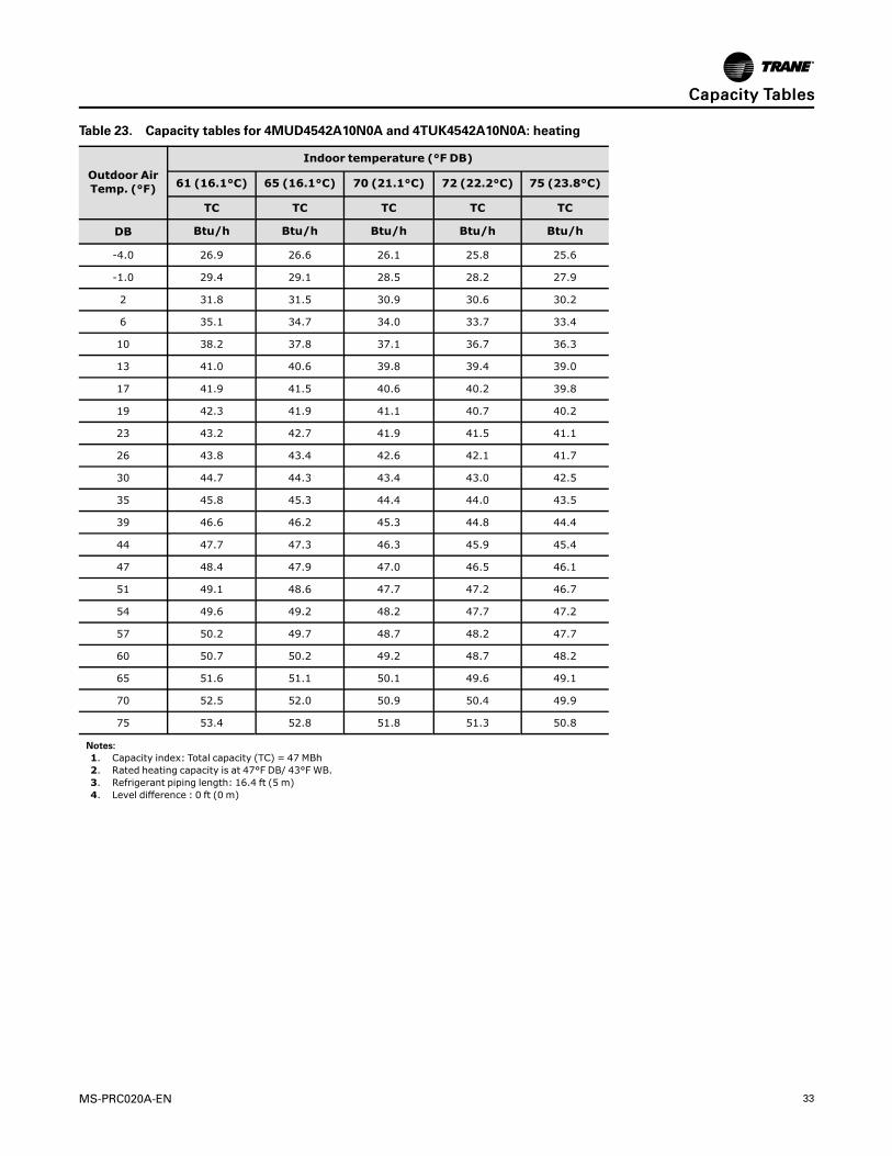
Table 23. Capacity tables for 4MUD4542A10N0A and 4TUK4542A10N0A: heating
Outdoor AirTemp. (°F)
Indoor temperature (°F DB)
61 (16.1°C) 65 (16.1°C) 70 (21.1°C) 72 (22.2°C) 75 (23.8°C)
TC TC TC TC TC
DB Btu/h Btu/h Btu/h Btu/h Btu/h
-4.0 26.9 26.6 26.1 25.8 25.6
-1.0 29.4 29.1 28.5 28.2 27.9
2 31.8 31.5 30.9 30.6 30.2
6 35.1 34.7 34.0 33.7 33.4
10 38.2 37.8 37.1 36.7 36.3
13 41.0 40.6 39.8 39.4 39.0
17 41.9 41.5 40.6 40.2 39.8
19 42.3 41.9 41.1 40.7 40.2
23 43.2 42.7 41.9 41.5 41.1
26 43.8 43.4 42.6 42.1 41.7
30 44.7 44.3 43.4 43.0 42.5
35 45.8 45.3 44.4 44.0 43.5
39 46.6 46.2 45.3 44.8 44.4
44 47.7 47.3 46.3 45.9 45.4
47 48.4 47.9 47.0 46.5 46.1
51 49.1 48.6 47.7 47.2 46.7
54 49.6 49.2 48.2 47.7 47.2
57 50.2 49.7 48.7 48.2 47.7
60 50.7 50.2 49.2 48.7 48.2
65 51.6 51.1 50.1 49.6 49.1
70 52.5 52.0 50.9 50.4 49.9
75 53.4 52.8 51.8 51.3 50.8
Notes:1. Capacity index: Total capacity (TC) = 47 MBh2. Rated heating capacity is at 47°F DB/ 43°F WB.3. Refrigerant piping length: 16.4 ft (5 m)4. Level difference : 0 ft (0 m)
CCaappaacciittyy TTaabblleess

34 MS-PRC020A-EN
Table 24. Capacity table for 4MUD4548A10N0A and 4TUK4548A10N0A (68°F, 73°F, 79°F, and 80°F): cooling
Outdoor AirTemp.(°F DB)
Indoor Temperature (°F)
68 (20.0°C, DB) 73 (22.8°C, DB) 79 (26.1°C, DB) 80 (26.7°C, DB)
57 (13.9°C, WB) 61 (19.4°C, WB) 64 (17.8°C, WB) 67 (19.4°C,WB)
TC(Btu/h)
SHC(Btu/h)
TC(Btu/h)
SHC(Btu/h)
TC(Btu/h)
SHC(Btu/h)
TC(Btu/h)
SHC(Btu/h)
0 50.1 40.1 51.5 41.2 52.8 42.3 53.8 43.0
10 50.0 40.0 51.3 41.1 52.7 42.2 53.7 42.9
20 49.9 39.9 51.2 40.9 52.6 42.0 53.5 42.8
30 49.7 39.8 51.0 40.8 52.4 41.9 53.4 42.7
40 49.6 39.7 50.9 40.7 52.3 41.8 53.2 42.6
50 49.5 39.6 50.8 40.6 52.1 41.7 53.1 42.5
54 49.4 39.5 50.7 40.6 52.1 41.7 53.0 42.4
58 49.3 39.5 50.7 40.5 52.0 41.6 53.0 42.4
60 49.3 39.5 50.6 40.5 52.0 41.6 52.9 42.4
64 49.3 39.4 50.6 40.5 51.9 41.5 52.9 42.3
67 49.2 39.4 50.5 40.4 51.9 41.5 52.8 42.3
70 49.2 39.4 50.5 40.4 51.8 41.5 52.8 42.2
73 48.7 38.9 50.0 40.0 51.3 41.0 52.2 41.8
77 47.9 38.3 49.2 39.4 50.5 40.4 51.5 41.2
80 47.4 37.9 48.7 38.9 50.0 40.0 50.9 40.7
84 46.7 37.3 47.9 38.3 49.2 39.4 50.1 40.1
88 46.0 36.8 47.2 37.8 48.5 38.8 49.3 39.5
92 45.3 36.2 46.5 37.2 47.7 38.2 48.6 38.9
95 44.7 35.8 45.9 36.7 47.1 37.7 48.0 38.4
99 41.6 33.3 42.7 34.2 43.8 35.1 44.6 35.7
103 38.5 30.8 39.5 31.6 40.5 32.4 41.3 33.0
107 35.3 28.3 36.3 29.0 37.2 29.8 37.9 30.3
111 32.2 25.8 33.1 26.4 33.9 27.2 34.6 27.6
115 29.1 23.3 29.8 23.9 30.6 24.5 31.2 25.0
Notes:1. Capacity index: Total capacity (TC) = 48 MBh; sensible heat capacity (SHC) = 38.4 MBh2. Indoor air temperatures (F° DB/WB) in cooling mode: 68/57, 72/61, 77/64, 80/67, 86/72, 90/75.3. Refrigerant piping length: 16.4 ft (5 m)4. Level difference : 0 ft (0 m)
CCaappaacciittyy TTaabblleess
MS-PRC020A-EN 35
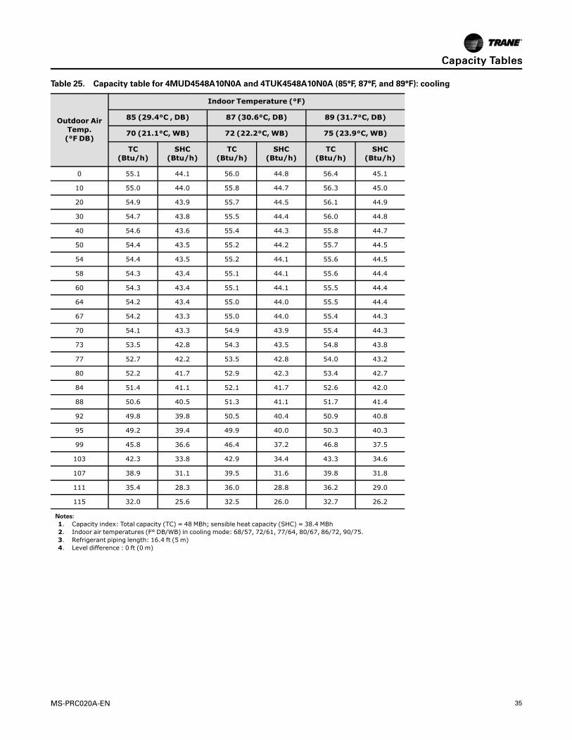
Table 25. Capacity table for 4MUD4548A10N0A and 4TUK4548A10N0A (85°F, 87°F, and 89°F): cooling
Outdoor AirTemp.(°F DB)
Indoor Temperature (°F)
85 (29.4°C , DB) 87 (30.6°C, DB) 89 (31.7°C, DB)
70 (21.1°C, WB) 72 (22.2°C, WB) 75 (23.9°C, WB)
TC(Btu/h)
SHC(Btu/h)
TC(Btu/h)
SHC(Btu/h)
TC(Btu/h)
SHC(Btu/h)
0 55.1 44.1 56.0 44.8 56.4 45.1
10 55.0 44.0 55.8 44.7 56.3 45.0
20 54.9 43.9 55.7 44.5 56.1 44.9
30 54.7 43.8 55.5 44.4 56.0 44.8
40 54.6 43.6 55.4 44.3 55.8 44.7
50 54.4 43.5 55.2 44.2 55.7 44.5
54 54.4 43.5 55.2 44.1 55.6 44.5
58 54.3 43.4 55.1 44.1 55.6 44.4
60 54.3 43.4 55.1 44.1 55.5 44.4
64 54.2 43.4 55.0 44.0 55.5 44.4
67 54.2 43.3 55.0 44.0 55.4 44.3
70 54.1 43.3 54.9 43.9 55.4 44.3
73 53.5 42.8 54.3 43.5 54.8 43.8
77 52.7 42.2 53.5 42.8 54.0 43.2
80 52.2 41.7 52.9 42.3 53.4 42.7
84 51.4 41.1 52.1 41.7 52.6 42.0
88 50.6 40.5 51.3 41.1 51.7 41.4
92 49.8 39.8 50.5 40.4 50.9 40.8
95 49.2 39.4 49.9 40.0 50.3 40.3
99 45.8 36.6 46.4 37.2 46.8 37.5
103 42.3 33.8 42.9 34.4 43.3 34.6
107 38.9 31.1 39.5 31.6 39.8 31.8
111 35.4 28.3 36.0 28.8 36.2 29.0
115 32.0 25.6 32.5 26.0 32.7 26.2
Notes:1. Capacity index: Total capacity (TC) = 48 MBh; sensible heat capacity (SHC) = 38.4 MBh2. Indoor air temperatures (F° DB/WB) in cooling mode: 68/57, 72/61, 77/64, 80/67, 86/72, 90/75.3. Refrigerant piping length: 16.4 ft (5 m)4. Level difference : 0 ft (0 m)
CCaappaacciittyy TTaabblleess

36 MS-PRC020A-EN
Table 26. Capacity table for 4MUD4548A10N0A and 4TUK4548A10N0A: heating
Outdoor AirTemp. (°F)
Indoor temperature (°F DB)
61 (16.1°C) 65 (16.1°C) 70 (21.1°C) 72 (22.2°C) 75 (23.8°C)
TC TC TC TC TC
DB Btu/h Btu/h Btu/h Btu/h Btu/h
-4.0 29.0 28.8 28.2 27.9 27.6
-1.0 31.6 31.3 30.7 30.4 30.1
2 34.1 33.8 33.1 32.8 32.4
6 37.5 37.1 36.4 36.0 35.6
10 40.7 40.3 39.5 39.1 38.7
13 43.6 43.1 42.3 41.9 41.5
17 44.9 44.4 43.6 43.1 42.7
19 45.5 45.1 44.2 43.7 43.3
23 46.8 46.3 45.4 45.0 44.5
26 47.8 47.3 46.4 45.9 45.5
30 49.1 48.6 47.7 47.2 46.7
35 50.7 50.2 49.2 48.7 48.2
39 52.0 51.4 50.4 49.9 49.4
44 53.6 53.1 52.0 51.5 51.0
47 54.6 54.1 53.0 52.5 51.9
51 55.8 55.2 54.1 53.6 53.1
54 56.7 56.1 55.0 54.5 53.9
57 57.5 56.9 55.8 55.3 54.7
60 58.4 57.8 56.7 56.1 55.6
65 59.9 59.3 58.1 57.6 57.0
70 61.4 60.8 59.6 59.0 58.4
75 62.8 62.2 61.0 60.4 59.8
Notes:1. Capacity index: Total capacity (TC) = 53 MBh2. Rated heating capacity is at 47°F DB/ 43°F WB.3. Refrigerant piping length: 16.4 ft (5 m)4. Level difference : 0 ft (0 m)
CCaappaacciittyy TTaabblleess
MS-PRC020A-EN 37
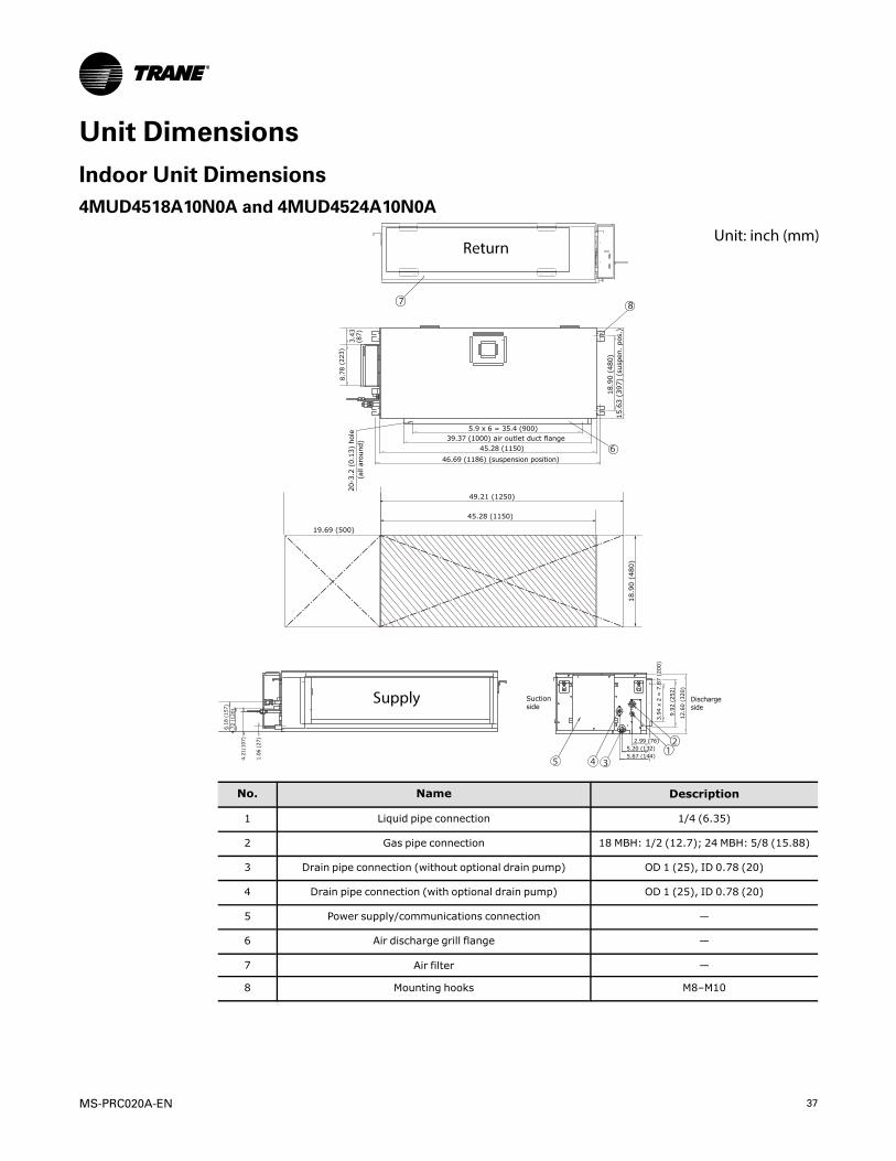
Unit DimensionsIndoor Unit Dimensions4MUD4518A10N0A and 4MUD4524A10N0A
8
6
7
5 4
21
3
Unit: inch (mm)Return
Supply
No. Name Description
1 Liquid pipe connection 1/4 (6.35)
2 Gas pipe connection 18 MBH: 1/2 (12.7); 24 MBH: 5/8 (15.88)
3 Drain pipe connection (without optional drain pump) OD 1 (25), ID 0.78 (20)
4 Drain pipe connection (with optional drain pump) OD 1 (25), ID 0.78 (20)
5 Power supply/communications connection —
6 Air discharge grill flange —
7 Air filter —
8 Mounting hooks M8–M10
38 MS-PRC020A-EN
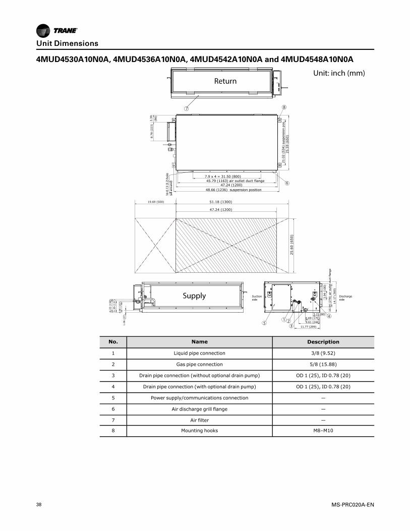
4MUD4530A10N0A, 4MUD4536A10N0A, 4MUD4542A10N0A and 4MUD4548A10N0A
7
6
8
5
41 2
3
Suct ionside
21
.02
(5
34
) su
spe
nsi
on
po
s.2
5.5
9 (
65
0)
25
.60
(6
50
)
7.9 x 4 = 31.50 (800)
51.18 (1300)
47.24 (1200)
19.69 (500)
8.7
8 (
22
3)
Dischargeside
3.3
9
(86
)
3.15 (80)6.69 (170)
9.61 (244)
11.77 (299)
14
.17
(3
60
)
14-0
.13
(3.2
) hol
e
1.0
6 (
27
)
(all
arou
nd) 45.79 (1163) air outlet duct flange
47.24 (1200)
48.66 (1236) suspension posit ion
10
.94
(2
78
) a
ir o
utl
et
du
ct f
lan
ge
3.9
4 (
10
0)
6.2
2 (
15
8)
5.3
9 (
13
7)
4.80
(12
2)
Unit: inch (mm)Return
Supply
No. Name Description
1 Liquid pipe connection 3/8 (9.52)
2 Gas pipe connection 5/8 (15.88)
3 Drain pipe connection (without optional drain pump) OD 1 (25), ID 0.78 (20)
4 Drain pipe connection (with optional drain pump) OD 1 (25), ID 0.78 (20)
5 Power supply/communications connection —
6 Air discharge grill flange —
7 Air filter —
8 Mounting hooks M8–M10
UUnniitt DDiimmeennssiioonnss

MS-PRC020A-EN 39
Outdoor Unit DimensionsFigure 1. Dimensional drawing for 18 MBH capacity units
12.20 (310)
25.12 (638)
14.33 (364)
34.65 (880) 2.60 (66)
0.47 (12)25.98 (660) 0.90 (23) Unit: inch (mm)
Figure 2. Dimensional drawing for 24 and 30 MBH capacity units
37.01 (940)
24.4 (620)
39
.29
(1
09
6)
38
.3 (
97
3)
15
.1 (
38
4)
14
.2 (
36
1)
13
.0 (
33
0)
20
.8 (
52
8)
21
.1 (
53
6)
26
.6 (
67
6)
Unit: inch (mm)
Figure 3. Dimensional drawing for 36, 42, and 48 MBH capacity units
24.4 (620)
46
.7 (
11
85
)
15
.1 (
38
4)
14.2
(36
1)
12
.99
(3
30
)
22
.0 (
55
9)
22
.3 (
56
6)
34
.8 (
88
4)
47
.64
(1
21
0)
37.01 (940)
Unit: inch (mm)
UUnniitt DDiimmeennssiioonnss
40 MS-PRC020A-EN
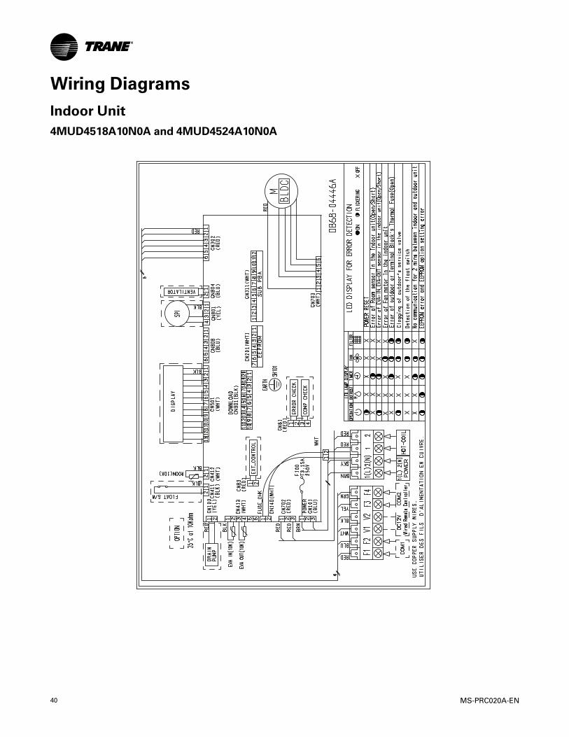
Wiring DiagramsIndoor Unit4MUD4518A10N0A and 4MUD4524A10N0A
MS-PRC020A-EN 41
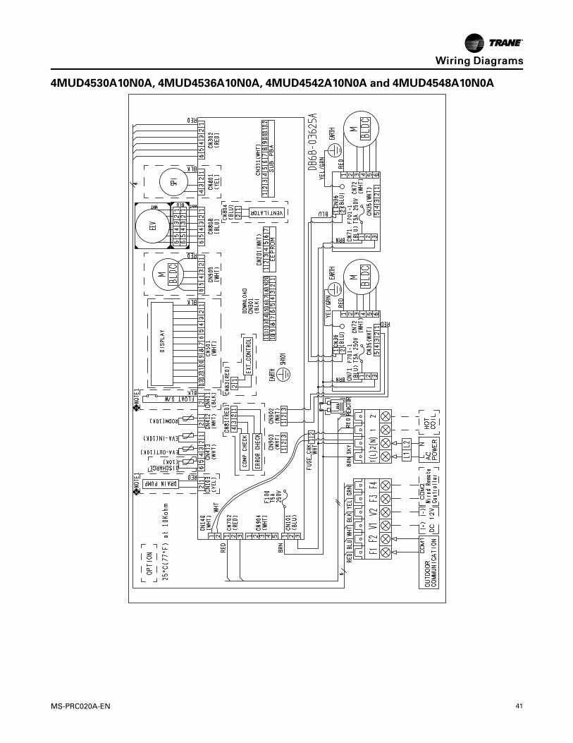
4MUD4530A10N0A, 4MUD4536A10N0A, 4MUD4542A10N0A and 4MUD4548A10N0A
WWiirriinngg DDiiaaggrraammss
42 MS-PRC020A-EN
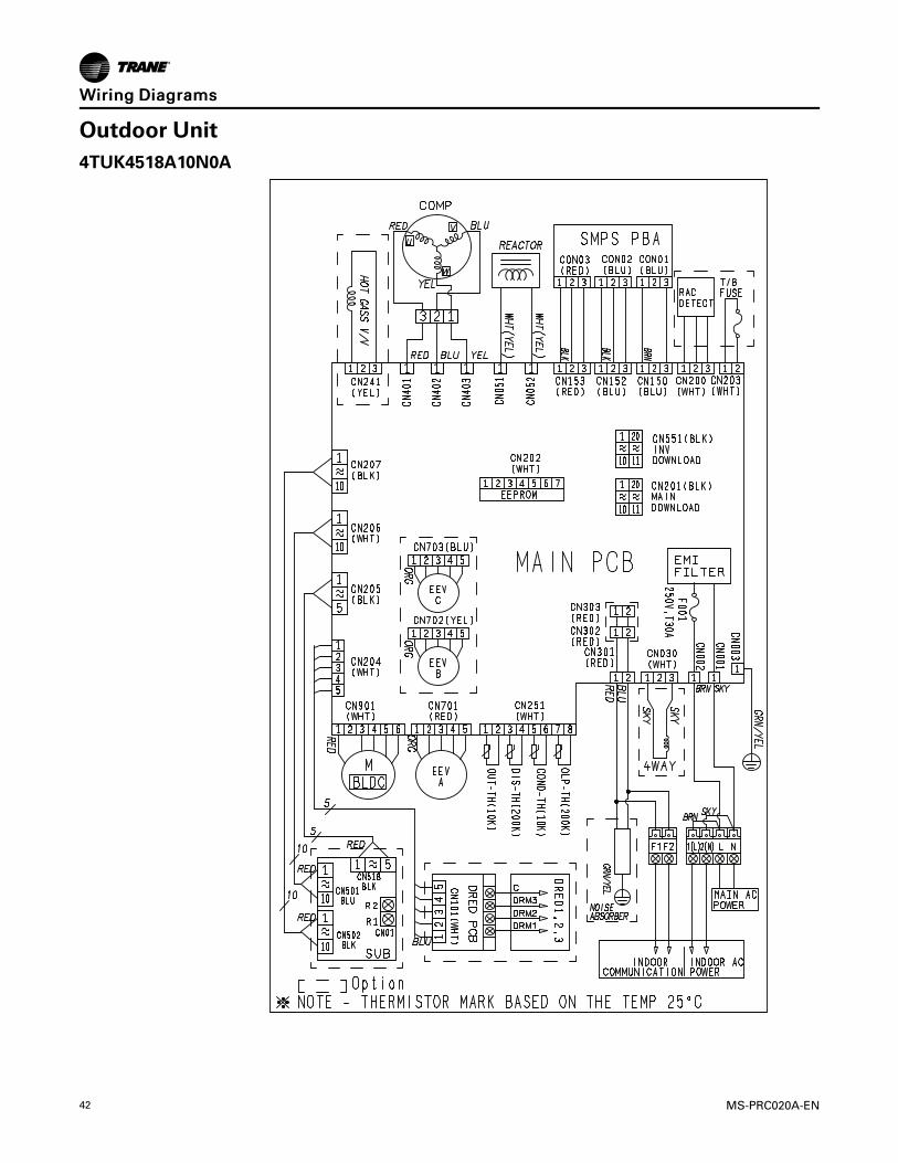
Outdoor Unit4TUK4518A10N0A
WWiirriinngg DDiiaaggrraammss

MS-PRC020A-EN 43
4TUK4524A10N0A, 4TUK4530A10N0A, 4TUK4536A10N0A, 4TUK4542A10N0A, and4TUK4548A10N0A
WWiirriinngg DDiiaaggrraammss
44 MS-PRC020A-EN
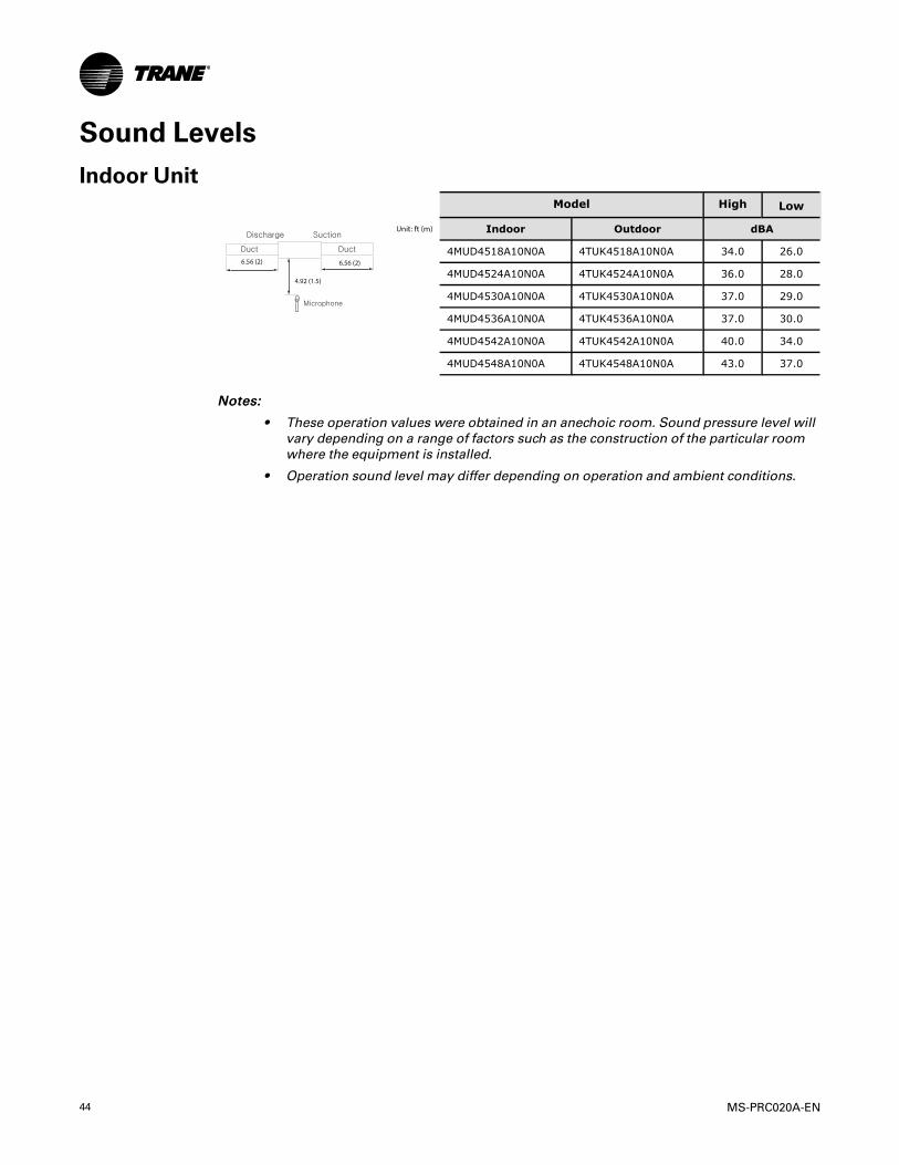
Sound LevelsIndoor Unit
Model High Low
Unit: ft (m)
4.92 (1.5)
6.56 (2)6.56 (2)
Indoor Outdoor dBA
4MUD4518A10N0A 4TUK4518A10N0A 34.0 26.0
4MUD4524A10N0A 4TUK4524A10N0A 36.0 28.0
4MUD4530A10N0A 4TUK4530A10N0A 37.0 29.0
4MUD4536A10N0A 4TUK4536A10N0A 37.0 30.0
4MUD4542A10N0A 4TUK4542A10N0A 40.0 34.0
4MUD4548A10N0A 4TUK4548A10N0A 43.0 37.0
NNootteess::
• These operation values were obtained in an anechoic room. Sound pressure level willvary depending on a range of factors such as the construction of the particular roomwhere the equipment is installed.
• Operation sound level may differ depending on operation and ambient conditions.
MS-PRC020A-EN 45
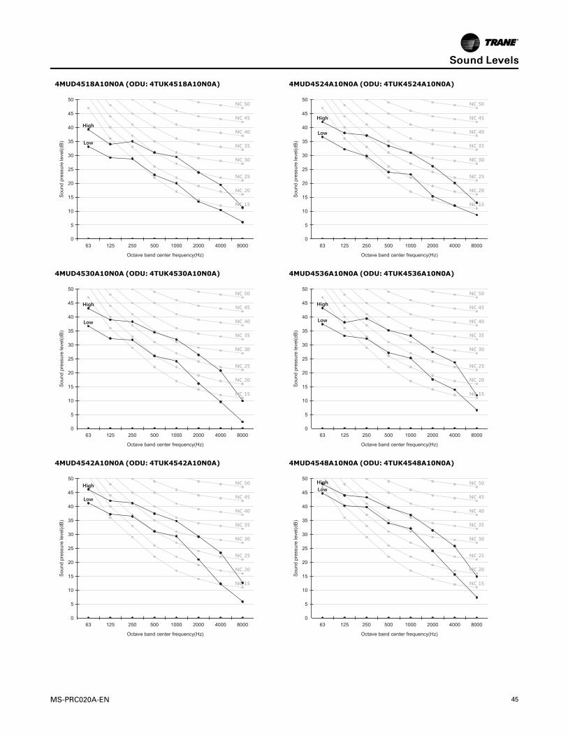
4MUD4518A10N0A (ODU: 4TUK4518A10N0A) 4MUD4524A10N0A (ODU: 4TUK4524A10N0A)
63 125 250 500 1000 2000 4000 8000
Octa e band center frequency(Hz)
0
5
10
15
20
25
30
35
40
45
50
Sou
nd p
ress
ure
leve
l(dB
)
63 125 250 500 1000 2000 4000 8000
Octa e band center frequency(Hz)
0
5
10
15
20
25
30
35
40
45
50
Sou
nd p
ress
ure
leve
l(dB
)
4MUD4530A10N0A (ODU: 4TUK4530A10N0A) 4MUD4536A10N0A (ODU: 4TUK4536A10N0A)
63 125 250 500 1000 2000 4000 8000
Octa e band center frequency(Hz)
0
5
10
15
20
25
30
35
40
45
50
Sou
nd p
ress
ure
leve
l(dB
)
63 125 250 500 1000 2000 4000 8000
Octa e band center frequency(Hz)
0
5
10
15
20
25
30
35
40
45
50S
ound
pre
ssur
e le
vel(d
B)
4MUD4542A10N0A (ODU: 4TUK4542A10N0A) 4MUD4548A10N0A (ODU: 4TUK4548A10N0A)
63 125 250 500 1000 2000 4000 8000
Octa e band center frequency(Hz)
0
5
10
15
20
25
30
35
40
45
50
Sou
nd p
ress
ure
leve
l(dB
)
63 125 250 500 1000 2000 4000 8000
Octa e band center frequency(Hz)
0
5
10
15
20
25
30
35
40
45
50
Sou
nd p
ress
ure
leve
l(dB
)
SSoouunndd LLeevveellss

46 MS-PRC020A-EN
Outdoor UnitModel Cooling Heating
3.28 (1) Unit: ft (m)
4.92 (1.5)
Microphone
Front
Indoor Outdoor dBA
4MUD4518A10N0A 4TUK4518A10N0A 48.0 48.0
4MUD4524A10N0A 4TUK4524A10N0A 50.0 50.0
4MUD4530A10N0A 4TUK4530A10N0A 50.0 52.0
4MUD4536A10N0A 4TUK4536A10N0A 49.0 51.0
4MUD4542A10N0A 4TUK4542A10N0A 51.0 53.0
4MUD4548A10N0A 4TUK4548A10N0A 53.0 55.0
SSoouunndd LLeevveellss
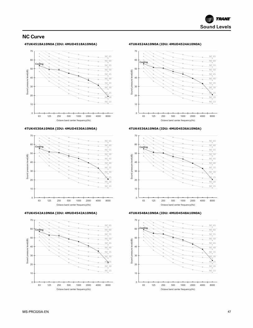
MS-PRC020A-EN 47
NC Curve4TUK4518A10N0A (IDU: 4MUD4518A10N0A) 4TUK4524A10N0A (IDU: 4MUD4524A10N0A)
63 125 250 500 1000 2000 4000 8000
Octa e band center frequency(Hz)
0
10
20
30
40
50
60
70
Sou
nd p
ress
ure
leve
l(dB
)
63 125 250 500 1000 2000 4000 8000
Octa e band center frequency(Hz)
0
10
20
30
40
50
60
70
Sou
nd p
ress
ure
leve
l(dB
)4TUK4530A10N0A (IDU: 4MUD4530A10N0A) 4TUK4536A10N0A (IDU: 4MUD4536A10N0A)
63 125 250 500 1000 2000 4000 8000
Octa e band center frequency(Hz)
0
10
20
30
40
50
60
70
Sou
nd p
ress
ure
leve
l(dB
)
63 125 250 500 1000 2000 4000 8000
Octa e band center frequency(Hz)
0
10
20
30
40
50
60
70
Sou
nd p
ress
ure
leve
l(dB
)
4TUK4542A10N0A (IDU: 4MUD4542A10N0A) 4TUK4548A10N0A (IDU: 4MUD4548A10N0A)
63 125 250 500 1000 2000 4000 8000
Octa e band center frequency(Hz)
0
10
20
30
40
50
60
70
Sou
nd p
ress
ure
leve
l(dB
)
63 125 250 500 1000 2000 4000 8000
Octa e band center frequency(Hz)
0
10
20
30
40
50
60
70
Sou
nd p
ress
ure
leve
l(dB
)
SSoouunndd LLeevveellss

48 MS-PRC020A-EN
Airflow DiagramsHow to Interpret P-Q Tables and Graphs
The following figure shows an example of how to interpret the P-Q curve tables and graphs. Each
box represents a static pressure range setpoint and shows its specific fan curve. Point 3
represents the highest available static pressure for each specific setting. When the fan is set to
Auto, the fan tracks from right to left within the box.
Figure 4. P-Q Curve Example
CFMin·Aq CFMin·Aq in·Aq CFM CFMin·Aq0.42 530 0.34 600 0.59 812 0.49 890
Low High
Point1(top, le� ) Point2(bo� om, right) Point4(bo� om,right)Point3(top,le� )
Lower Sta! c Range
Upper Sta! c Range

MS-PRC020A-EN 49
4MUD4518A10N0AP-Q data Low High
External Static pressure(in·Aq)Point 1 (top, left) Point 2 (bottom,left) Point 3 (top,right) Point 4 (bottom,right)
in·Aq CFM in·Aq CFM in·Aq CFM in·Aq CFM
0≤P≤0.12(Default) 0.05 406 0.01 452 0.12 639 0.06 689
0.12<P≤0.20 0.11 403 0.05 452 0.20 639 0.12 692
0.20<P≤0.30 0.18 403 0.10 452 0.30 639 0.20 696
0.30<P≤0.40 0.26 403 0.18 452 0.39 639 0.30 696
0.40<P≤0.50 0.33 403 0.25 452 0.49 639 0.39 696
0.50<P≤0.60 0.41 403 0.33 452 0.59 639 0.49 696
Figure 5. 4MUD4518A10N0A P-Q Curve Example
AAiirrffllooww DDiiaaggrraammss
50 MS-PRC020A-EN
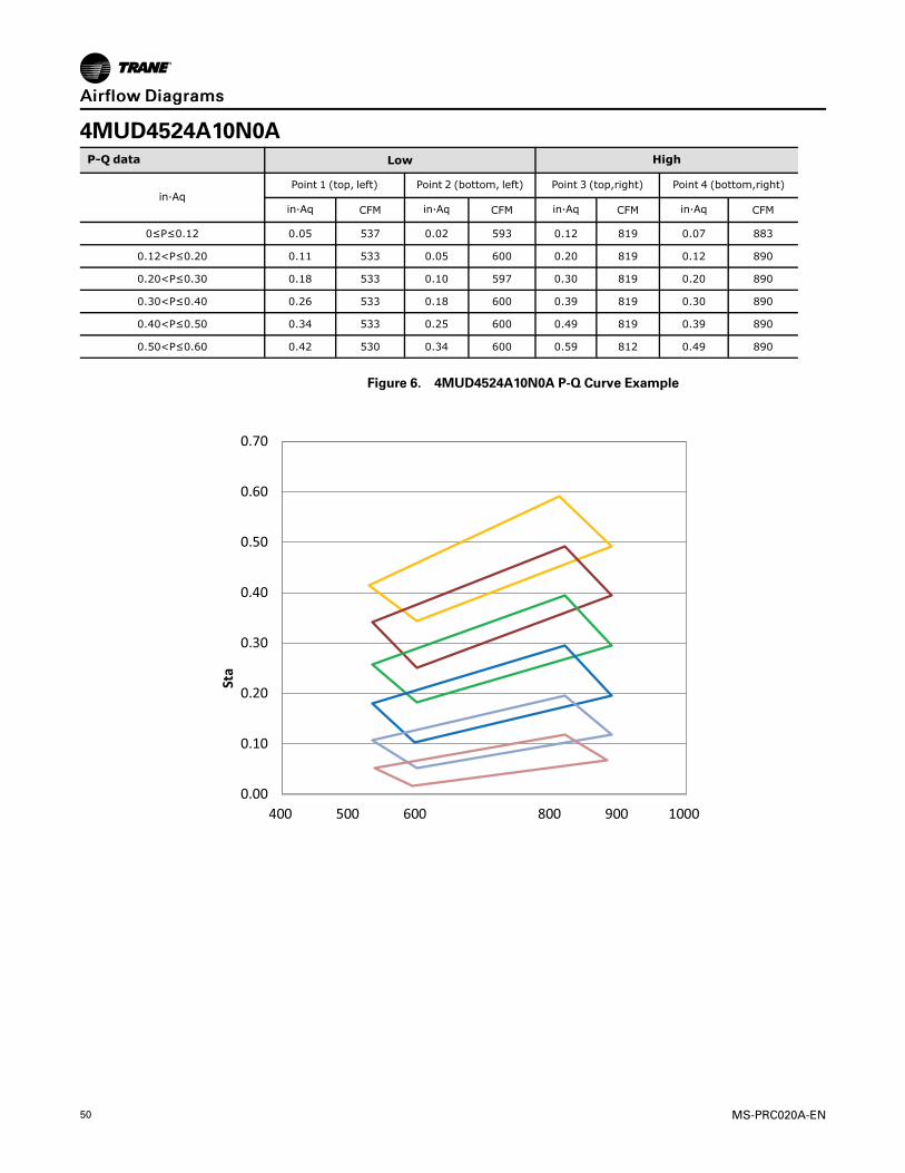
4MUD4524A10N0AP-Q data Low High
in·AqPoint 1 (top, left) Point 2 (bottom, left) Point 3 (top,right) Point 4 (bottom,right)
in·Aq CFM in·Aq CFM in·Aq CFM in·Aq CFM
0≤P≤0.12 0.05 537 0.02 593 0.12 819 0.07 883
0.12<P≤0.20 0.11 533 0.05 600 0.20 819 0.12 890
0.20<P≤0.30 0.18 533 0.10 597 0.30 819 0.20 890
0.30<P≤0.40 0.26 533 0.18 600 0.39 819 0.30 890
0.40<P≤0.50 0.34 533 0.25 600 0.49 819 0.39 890
0.50<P≤0.60 0.42 530 0.34 600 0.59 812 0.49 890
Figure 6. 4MUD4524A10N0A P-Q Curve Example
0.00
0.10
0.20
0.30
0.40
0.50
0.60
0.70
400 500 600 800 900 1000
Sta
c Pr
essu
re (i
n·A
q)
700
Air Flow (CFM)
P-Q Curve
0.50:: P≤0.60
0.40:: P≤0.50
0.30:: P≤0.40
0.20:: P≤0.30
0.12:: P≤0.20
0≤P≤0.12
High
Low
AAiirrffllooww DDiiaaggrraammss
MS-PRC020A-EN 51
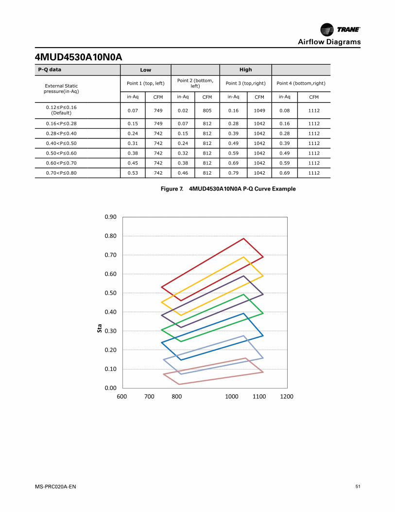
4MUD4530A10N0AP-Q data Low High
External Staticpressure(in·Aq)
Point 1 (top, left)Point 2 (bottom,
left)Point 3 (top,right) Point 4 (bottom,right)
in·Aq CFM in·Aq CFM in·Aq CFM in·Aq CFM
0.12≤P≤0.16(Default) 0.07 749 0.02 805 0.16 1049 0.08 1112
0.16<P≤0.28 0.15 749 0.07 812 0.28 1042 0.16 1112
0.28<P≤0.40 0.24 742 0.15 812 0.39 1042 0.28 1112
0.40<P≤0.50 0.31 742 0.24 812 0.49 1042 0.39 1112
0.50<P≤0.60 0.38 742 0.32 812 0.59 1042 0.49 1112
0.60<P≤0.70 0.45 742 0.38 812 0.69 1042 0.59 1112
0.70<P≤0.80 0.53 742 0.46 812 0.79 1042 0.69 1112
Figure 7. 4MUD4530A10N0A P-Q Curve Example
0.00
0.10
0.20
0.30
0.40
0.50
0.60
0.70
0.80
0.90
600 700 800 1000 1100 1200
Sta
c Pr
essu
re (
in·A
q)
900
Air Flow (CFM)
P-Q Curve
0.70:: P≤0.80
0.60:: P≤0.70
0.50:: P≤0.60
0.40:: P≤0.50
0.28:: P≤0.40
0.16:: P≤0.28
Low
0.12≤P≤0.16(Default)
High
AAiirrffllooww DDiiaaggrraammss
52 MS-PRC020A-EN
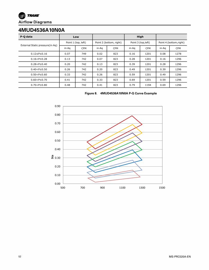
4MUD4536A10N0AP-Q data Low High
External Static pressure(in·Aq)Point 1 (top, left) Point 2 (bottom, right) Point 3 (top,left) Point 4 (bottom,right)
in·Aq CFM in·Aq CFM in·Aq CFM in·Aq CFM
0.12≤P≤0.16 0.07 749 0.02 823 0.16 1201 0.08 1278
0.16<P≤0.28 0.13 742 0.07 823 0.28 1201 0.16 1296
0.28<P≤0.40 0.20 742 0.13 823 0.39 1201 0.28 1296
0.40<P≤0.50 0.26 742 0.20 823 0.49 1201 0.39 1296
0.50<P≤0.60 0.33 742 0.26 823 0.59 1201 0.49 1296
0.60<P≤0.70 0.41 742 0.33 823 0.69 1201 0.59 1296
0.70<P≤0.80 0.48 742 0.41 823 0.79 1194 0.69 1296
Figure 8. 4MUD4536A10N0A P-Q Curve Example
0.00
0.10
0.20
0.30
0.40
0.50
0.60
0.70
0.80
0.90
500 700 900 1100 1300 1500
Sta
c Pr
essu
re (
in·A
q)
Air Flow (CFM)
P-Q Curve
0.70:: P≤0.80
0.60:: P≤0.70
0.50:: P≤0.60
0.40:: P≤0.50
0.28:: P≤0.40
0.16:: P≤0.28
0.12≤P≤0.16
High
Low
AAiirrffllooww DDiiaaggrraammss
MS-PRC020A-EN 53
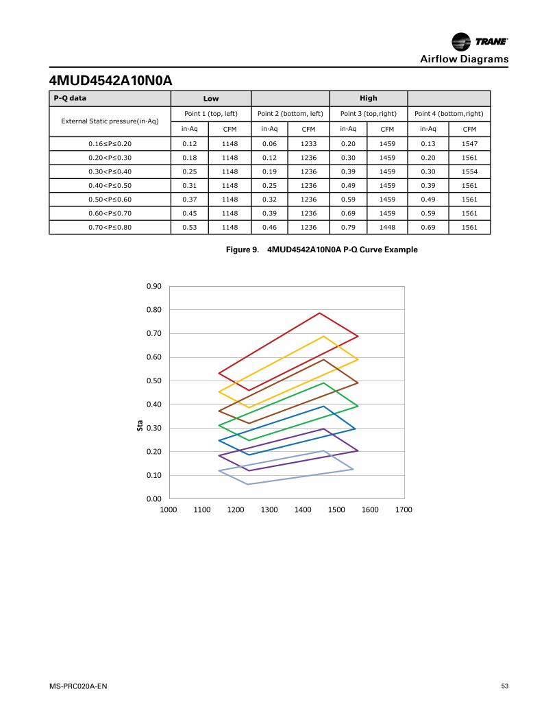
4MUD4542A10N0AP-Q data Low High
External Static pressure(in·Aq)Point 1 (top, left) Point 2 (bottom, left) Point 3 (top,right) Point 4 (bottom,right)
in·Aq CFM in·Aq CFM in·Aq CFM in·Aq CFM
0.16≤P≤0.20 0.12 1148 0.06 1233 0.20 1459 0.13 1547
0.20<P≤0.30 0.18 1148 0.12 1236 0.30 1459 0.20 1561
0.30<P≤0.40 0.25 1148 0.19 1236 0.39 1459 0.30 1554
0.40<P≤0.50 0.31 1148 0.25 1236 0.49 1459 0.39 1561
0.50<P≤0.60 0.37 1148 0.32 1236 0.59 1459 0.49 1561
0.60<P≤0.70 0.45 1148 0.39 1236 0.69 1459 0.59 1561
0.70<P≤0.80 0.53 1148 0.46 1236 0.79 1448 0.69 1561
Figure 9. 4MUD4542A10N0A P-Q Curve Example
0.00
0.10
0.20
0.30
0.40
0.50
0.60
0.70
0.80
0.90
1000 1100 1200 1300 1400 1500 1600 1700
Sta
c Pr
essu
re (
in·A
q)
P-Q Curve
Low
0.16≤P≤0.20(Default)
High
0.70:: P≤0.80
0.60:: P≤0.70
0.50:: P≤0.60
0.40:: P≤0.50
0.30:: P≤0.40
0.20:: P≤0.30
AAiirrffllooww DDiiaaggrraammss
54 MS-PRC020A-EN
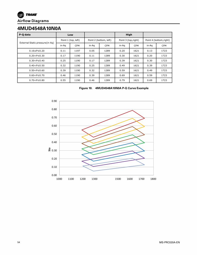
4MUD4548A10N0AP-Q data Low High
External Static pressure(in·Aq)Point 1 (top, left) Point 2 (bottom, left) Point 3 (top,right) Point 4 (bottom,right)
in·Aq CFM in·Aq CFM in·Aq CFM in·Aq CFM
0.16≤P≤0.20 0.11 1197 0.05 1289 0.20 1621 0.13 1723
0.20<P≤0.30 0.17 1190 0.11 1289 0.30 1621 0.20 1723
0.30<P≤0.40 0.25 1190 0.17 1289 0.39 1621 0.30 1723
0.40<P≤0.50 0.32 1190 0.25 1289 0.49 1621 0.39 1723
0.50<P≤0.60 0.39 1190 0.32 1289 0.59 1621 0.49 1723
0.60<P≤0.70 0.46 1190 0.39 1289 0.69 1621 0.59 1723
0.70<P≤0.80 0.55 1190 0.46 1289 0.79 1621 0.69 1723
Figure 10. 4MUD4548A10N0A P-Q Curve Example
0.00
0.10
0.20
0.30
0.40
0.50
0.60
0.70
0.80
0.90
1000 1100 1200 1300 1500 1600 1700 1800
Sta�
c Pr
essu
re (i
n·A
q)
1400
Air Flow (CFM)
P-Q Curve
0.70:: P≤0.80
0.60:: P≤0.70
0.50:: P≤0.60
0.40:: P≤0.50
0.30:: P≤0.40
0.20:: P≤0.30
0.16≤P≤0.20
Low
High
AAiirrffllooww DDiiaaggrraammss
MS-PRC020A-EN 55
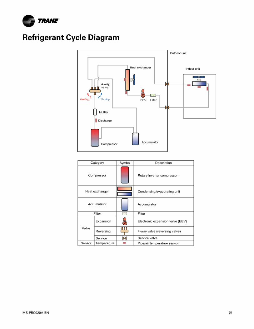
Refrigerant Cycle Diagram
Symbol Description
Rotary inverter compressor
Accumulator
Filter
Expansion
Condensing/evaporating unit
Electronic expansion valve (EEV)
Reversing
Service Service valve
Sens r
4-way valve (reversing valve)
Temperature
Valve
Category
Compressor
Heat exchanger
Filter
Accumulator
���
���
���
���
CompressorAccumulator
Outdoor unit
Indoor unit
4-wayvalve
EEV Filter
Heat exchanger
Discharge
Muffler
Pipe/air temperature sensor
56 MS-PRC020A-EN
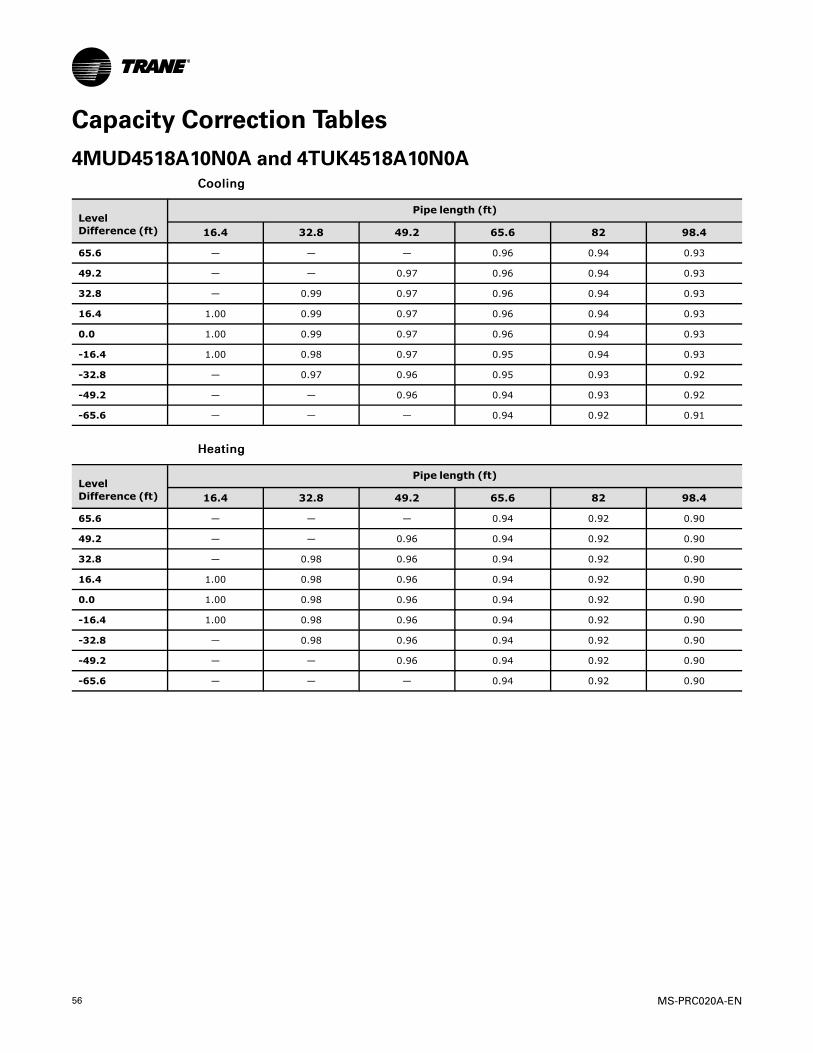
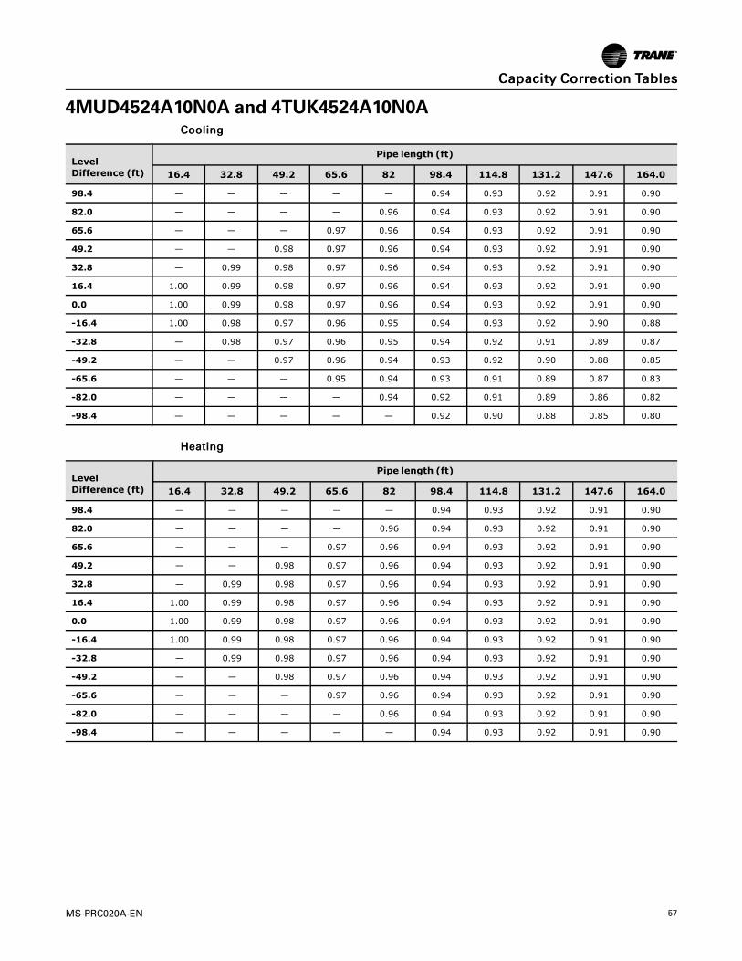
Capacity Correction Tables4MUD4518A10N0A and 4TUK4518A10N0A
CCoooolliinngg
LevelDifference (ft)
Pipe length (ft)
16.4 32.8 49.2 65.6 82 98.4
65.6 — — — 0.96 0.94 0.93
49.2 — — 0.97 0.96 0.94 0.93
32.8 — 0.99 0.97 0.96 0.94 0.93
16.4 1.00 0.99 0.97 0.96 0.94 0.93
0.0 1.00 0.99 0.97 0.96 0.94 0.93
-16.4 1.00 0.98 0.97 0.95 0.94 0.93
-32.8 — 0.97 0.96 0.95 0.93 0.92
-49.2 — — 0.96 0.94 0.93 0.92
-65.6 — — — 0.94 0.92 0.91
HHeeaattiinngg
LevelDifference (ft)
Pipe length (ft)
16.4 32.8 49.2 65.6 82 98.4
65.6 — — — 0.94 0.92 0.90
49.2 — — 0.96 0.94 0.92 0.90
32.8 — 0.98 0.96 0.94 0.92 0.90
16.4 1.00 0.98 0.96 0.94 0.92 0.90
0.0 1.00 0.98 0.96 0.94 0.92 0.90
-16.4 1.00 0.98 0.96 0.94 0.92 0.90
-32.8 — 0.98 0.96 0.94 0.92 0.90
-49.2 — — 0.96 0.94 0.92 0.90
-65.6 — — — 0.94 0.92 0.90
MS-PRC020A-EN 57
4MUD4524A10N0A and 4TUK4524A10N0ACCoooolliinngg
LevelDifference (ft)
Pipe length (ft)
16.4 32.8 49.2 65.6 82 98.4 114.8 131.2 147.6 164.0
98.4 — — — — — 0.94 0.93 0.92 0.91 0.90
82.0 — — — — 0.96 0.94 0.93 0.92 0.91 0.90
65.6 — — — 0.97 0.96 0.94 0.93 0.92 0.91 0.90
49.2 — — 0.98 0.97 0.96 0.94 0.93 0.92 0.91 0.90
32.8 — 0.99 0.98 0.97 0.96 0.94 0.93 0.92 0.91 0.90
16.4 1.00 0.99 0.98 0.97 0.96 0.94 0.93 0.92 0.91 0.90
0.0 1.00 0.99 0.98 0.97 0.96 0.94 0.93 0.92 0.91 0.90
-16.4 1.00 0.98 0.97 0.96 0.95 0.94 0.93 0.92 0.90 0.88
-32.8 — 0.98 0.97 0.96 0.95 0.94 0.92 0.91 0.89 0.87
-49.2 — — 0.97 0.96 0.94 0.93 0.92 0.90 0.88 0.85
-65.6 — — — 0.95 0.94 0.93 0.91 0.89 0.87 0.83
-82.0 — — — — 0.94 0.92 0.91 0.89 0.86 0.82
-98.4 — — — — — 0.92 0.90 0.88 0.85 0.80
HHeeaattiinngg
LevelDifference (ft)
Pipe length (ft)
16.4 32.8 49.2 65.6 82 98.4 114.8 131.2 147.6 164.0
98.4 — — — — — 0.94 0.93 0.92 0.91 0.90
82.0 — — — — 0.96 0.94 0.93 0.92 0.91 0.90
65.6 — — — 0.97 0.96 0.94 0.93 0.92 0.91 0.90
49.2 — — 0.98 0.97 0.96 0.94 0.93 0.92 0.91 0.90
32.8 — 0.99 0.98 0.97 0.96 0.94 0.93 0.92 0.91 0.90
16.4 1.00 0.99 0.98 0.97 0.96 0.94 0.93 0.92 0.91 0.90
0.0 1.00 0.99 0.98 0.97 0.96 0.94 0.93 0.92 0.91 0.90
-16.4 1.00 0.99 0.98 0.97 0.96 0.94 0.93 0.92 0.91 0.90
-32.8 — 0.99 0.98 0.97 0.96 0.94 0.93 0.92 0.91 0.90
-49.2 — — 0.98 0.97 0.96 0.94 0.93 0.92 0.91 0.90
-65.6 — — — 0.97 0.96 0.94 0.93 0.92 0.91 0.90
-82.0 — — — — 0.96 0.94 0.93 0.92 0.91 0.90
-98.4 — — — — — 0.94 0.93 0.92 0.91 0.90
CCaappaacciittyy CCoorrrreeccttiioonn TTaabblleess
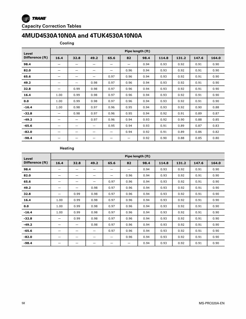
58 MS-PRC020A-EN
4MUD4530A10N0A and 4TUK4530A10N0ACCoooolliinngg
LevelDifference (ft)
Pipe length (ft)
16.4 32.8 49.2 65.6 82 98.4 114.8 131.2 147.6 164.0
98.4 — — — — — 0.94 0.93 0.92 0.91 0.90
82.0 — — — — 0.96 0.94 0.93 0.92 0.91 0.90
65.6 — — — 0.97 0.96 0.94 0.93 0.92 0.91 0.90
49.2 — — 0.98 0.97 0.96 0.94 0.93 0.92 0.91 0.90
32.8 — 0.99 0.98 0.97 0.96 0.94 0.93 0.92 0.91 0.90
16.4 1.00 0.99 0.98 0.97 0.96 0.94 0.93 0.92 0.91 0.90
0.0 1.00 0.99 0.98 0.97 0.96 0.94 0.93 0.92 0.91 0.90
-16.4 1.00 0.98 0.97 0.96 0.95 0.94 0.93 0.92 0.90 0.88
-32.8 — 0.98 0.97 0.96 0.95 0.94 0.92 0.91 0.89 0.87
-49.2 — — 0.97 0.96 0.94 0.93 0.92 0.90 0.88 0.85
-65.6 — — — 0.95 0.94 0.93 0.91 0.89 0.87 0.83
-82.0 — — — — 0.94 0.92 0.91 0.89 0.86 0.82
-98.4 — — — — — 0.92 0.90 0.88 0.85 0.80
HHeeaattiinngg
LevelDifference (ft)
Pipe length (ft)
16.4 32.8 49.2 65.6 82 98.4 114.8 131.2 147.6 164.0
98.4 — — — — — 0.94 0.93 0.92 0.91 0.90
82.0 — — — — 0.96 0.94 0.93 0.92 0.91 0.90
65.6 — — — 0.97 0.96 0.94 0.93 0.92 0.91 0.90
49.2 — — 0.98 0.97 0.96 0.94 0.93 0.92 0.91 0.90
32.8 — 0.99 0.98 0.97 0.96 0.94 0.93 0.92 0.91 0.90
16.4 1.00 0.99 0.98 0.97 0.96 0.94 0.93 0.92 0.91 0.90
0.0 1.00 0.99 0.98 0.97 0.96 0.94 0.93 0.92 0.91 0.90
-16.4 1.00 0.99 0.98 0.97 0.96 0.94 0.93 0.92 0.91 0.90
-32.8 — 0.99 0.98 0.97 0.96 0.94 0.93 0.92 0.91 0.90
-49.2 — — 0.98 0.97 0.96 0.94 0.93 0.92 0.91 0.90
-65.6 — — — 0.97 0.96 0.94 0.93 0.92 0.91 0.90
-82.0 — — — — 0.96 0.94 0.93 0.92 0.91 0.90
-98.4 — — — — — 0.94 0.93 0.92 0.91 0.90
CCaappaacciittyy CCoorrrreeccttiioonn TTaabblleess

MS-PRC020A-EN 59
4MUD4536A10N0A and 4TUK4536A10N0ACCoooolliinngg
LevelDiffer-ence(ft)
Pipe length (ft)
16.4 32.8 49.2 65.6 82 98.4 114.8 131.2 147.6 164.0 180.4 196.9 213.3 229.7 246.1
98.4 — — — — — 0.96 0.95 0.94 0.93 0.92 0.91 0.91 0.90 0.89 0.88
82.0 — — — — 0.97 0.96 0.95 0.94 0.93 0.92 0.91 0.91 0.90 0.89 0.88
65.6 — — — 0.97 0.97 0.96 0.95 0.94 0.93 0.92 0.91 0.91 0.90 0.89 0.88
49.2 — — 0.98 0.97 0.97 0.96 0.95 0.94 0.93 0.92 0.91 0.91 0.90 0.89 0.88
32.8 — 0.99 0.98 0.97 0.97 0.96 0.95 0.94 0.93 0.92 0.91 0.91 0.90 0.89 0.88
16.4 1.00 0.99 0.98 0.97 0.97 0.96 0.95 0.94 0.93 0.92 0.91 0.91 0.90 0.89 0.88
0.0 1.00 0.99 0.98 0.97 0.97 0.96 0.95 0.94 0.93 0.92 0.91 0.91 0.90 0.89 0.88
-16.4 1.00 0.99 0.98 0.97 0.96 0.95 0.95 0.94 0.93 0.92 0.91 0.90 0.89 0.88 0.87
-32.8 — 0.98 0.98 0.97 0.96 0.95 0.94 0.93 0.93 0.92 0.91 0.90 0.89 0.87 0.85
-49.2 — — 0.97 0.97 0.96 0.95 0.94 0.93 0.92 0.91 0.90 0.89 0.88 0.86 0.84
-65.6 — — — 0.96 0.95 0.95 0.94 0.93 0.92 0.91 0.90 0.89 0.88 0.86 0.83
-82.0 — — — — 0.95 0.94 0.93 0.93 0.92 0.91 0.90 0.88 0.87 0.85 0.81
-98.4 — — — — — 0.94 0.93 0.92 0.91 0.90 0.89 0.88 0.86 0.84 0.80
HHeeaattiinngg
LevelDiffer-ence(ft)
Pipe length (ft)
16.4 32.8 49.2 65.6 82 98.4 114.8 131.2 147.6 164.0 180.4 196.9 213.3 229.7 246.1
98.4 — — — — — 0.96 0.95 0.94 0.93 0.92 0.91 0.91 0.90 0.89 0.88
82.0 — — — — 0.97 0.96 0.95 0.94 0.93 0.92 0.91 0.91 0.90 0.89 0.88
65.6 — — — 0.97 0.97 0.96 0.95 0.94 0.93 0.92 0.91 0.91 0.90 0.89 0.88
49.2 — — 0.98 0.97 0.97 0.96 0.95 0.94 0.93 0.92 0.91 0.91 0.90 0.89 0.88
32.8 — 0.99 0.98 0.97 0.97 0.96 0.95 0.94 0.93 0.92 0.91 0.91 0.90 0.89 0.88
16.4 1.00 0.99 0.98 0.97 0.97 0.96 0.95 0.94 0.93 0.92 0.91 0.91 0.90 0.89 0.88
0.0 1.00 0.99 0.98 0.97 0.97 0.96 0.95 0.94 0.93 0.92 0.91 0.91 0.90 0.89 0.88
-16.4 1.00 0.99 0.98 0.97 0.97 0.96 0.95 0.94 0.93 0.92 0.91 0.91 0.90 0.88 0.88
-32.8 — 0.99 0.98 0.97 0.97 0.96 0.95 0.94 0.93 0.92 0.91 0.91 0.90 0.89 0.88
-49.2 — — 0.98 0.97 0.97 0.96 0.95 0.94 0.93 0.92 0.91 0.91 0.90 0.89 0.88
-65.6 — — — 0.97 0.97 0.96 0.95 0.94 0.93 0.92 0.91 0.91 0.90 0.89 0.88
-82.0 — — — — 0.97 0.96 0.95 0.94 0.93 0.92 0.91 0.91 0.90 0.89 0.88
-98.4 — — — — — 0.96 0.95 0.94 0.93 0.92 0.91 0.91 0.90 0.89 0.88
CCaappaacciittyy CCoorrrreeccttiioonn TTaabblleess

60 MS-PRC020A-EN
4MUD4542A10N0A and 4TUK4542A10N0ACCoooolliinngg
LevelDiffer-ence(ft)
Pipe length (ft)
16.4 32.8 49.2 65.6 82 98.4 114.8 131.2 147.6 164.0 180.4 196.9 213.3 229.7 246.1
98.4 — — — — — 0.96 0.95 0.94 0.93 0.92 0.91 0.91 0.90 0.89 0.88
82.0 — — — — 0.97 0.96 0.95 0.94 0.93 0.92 0.91 0.91 0.90 0.89 0.88
65.6 — — — 0.97 0.97 0.96 0.95 0.94 0.93 0.92 0.91 0.91 0.90 0.89 0.88
49.2 — — 0.98 0.97 0.97 0.96 0.95 0.94 0.93 0.92 0.91 0.91 0.90 0.89 0.88
32.8 — 0.99 0.98 0.97 0.97 0.96 0.95 0.94 0.93 0.92 0.91 0.91 0.90 0.89 0.88
16.4 1.00 0.99 0.98 0.97 0.97 0.96 0.95 0.94 0.93 0.92 0.91 0.91 0.90 0.89 0.88
0.0 1.00 0.99 0.98 0.97 0.97 0.96 0.95 0.94 0.93 0.92 0.91 0.91 0.90 0.89 0.88
-16.4 1.00 0.99 0.98 0.97 0.96 0.95 0.95 0.94 0.93 0.92 0.91 0.90 0.89 0.88 0.87
-32.8 — 0.98 0.98 0.97 0.96 0.95 0.94 0.93 0.93 0.92 0.91 0.90 0.89 0.87 0.85
-49.2 — — 0.97 0.97 0.96 0.95 0.94 0.93 0.92 0.91 0.90 0.89 0.88 0.86 0.84
-65.6 — — — 0.96 0.95 0.95 0.94 0.93 0.92 0.91 0.90 0.89 0.88 0.86 0.83
-82.0 — — — — 0.95 0.94 0.93 0.93 0.92 0.91 0.90 0.88 0.87 0.85 0.81
-98.4 — — — — — 0.94 0.93 0.92 0.91 0.90 0.89 0.88 0.86 0.84 0.80
HHeeaattiinngg
LevelDiffer-ence(ft)
Pipe length (ft)
16.4 32.8 49.2 65.6 82 98.4 114.8 131.2 147.6 164.0 180.4 196.9 213.3 229.7 246.1
98.4 — — — — — 0.96 0.95 0.94 0.93 0.92 0.91 0.91 0.90 0.89 0.88
82.0 — — — — 0.97 0.96 0.95 0.94 0.93 0.92 0.91 0.91 0.90 0.89 0.88
65.6 — — — 0.97 0.97 0.96 0.95 0.94 0.93 0.92 0.91 0.91 0.90 0.89 0.88
49.2 — — 0.98 0.97 0.97 0.96 0.95 0.94 0.93 0.92 0.91 0.91 0.90 0.89 0.88
32.8 — 0.99 0.98 0.97 0.97 0.96 0.95 0.94 0.93 0.92 0.91 0.91 0.90 0.89 0.88
16.4 1.00 0.99 0.98 0.97 0.97 0.96 0.95 0.94 0.93 0.92 0.91 0.91 0.90 0.89 0.88
0.0 1.00 0.99 0.98 0.97 0.97 0.96 0.95 0.94 0.93 0.92 0.91 0.91 0.90 0.89 0.88
-16.4 1.00 0.99 0.98 0.97 0.97 0.96 0.95 0.94 0.93 0.92 0.91 0.91 0.90 0.88 0.88
-32.8 — 0.99 0.98 0.97 0.97 0.96 0.95 0.94 0.93 0.92 0.91 0.91 0.90 0.89 0.88
-49.2 — — 0.98 0.97 0.97 0.96 0.95 0.94 0.93 0.92 0.91 0.91 0.90 0.89 0.88
-65.6 — — — 0.97 0.97 0.96 0.95 0.94 0.93 0.92 0.91 0.91 0.90 0.89 0.88
-82.0 — — — — 0.97 0.96 0.95 0.94 0.93 0.92 0.91 0.91 0.90 0.89 0.88
-98.4 — — — — — 0.96 0.95 0.94 0.93 0.92 0.91 0.91 0.90 0.89 0.88
CCaappaacciittyy CCoorrrreeccttiioonn TTaabblleess
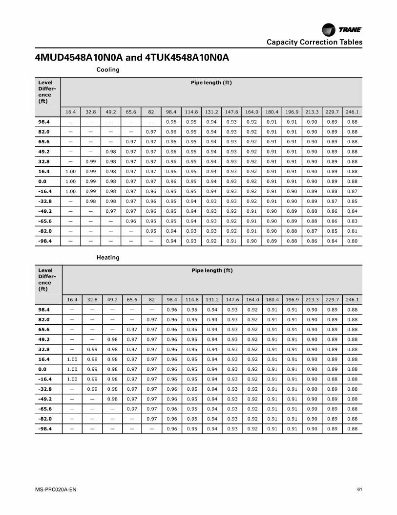
MS-PRC020A-EN 61
4MUD4548A10N0A and 4TUK4548A10N0ACCoooolliinngg
LevelDiffer-ence(ft)
Pipe length (ft)
16.4 32.8 49.2 65.6 82 98.4 114.8 131.2 147.6 164.0 180.4 196.9 213.3 229.7 246.1
98.4 — — — — — 0.96 0.95 0.94 0.93 0.92 0.91 0.91 0.90 0.89 0.88
82.0 — — — — 0.97 0.96 0.95 0.94 0.93 0.92 0.91 0.91 0.90 0.89 0.88
65.6 — — — 0.97 0.97 0.96 0.95 0.94 0.93 0.92 0.91 0.91 0.90 0.89 0.88
49.2 — — 0.98 0.97 0.97 0.96 0.95 0.94 0.93 0.92 0.91 0.91 0.90 0.89 0.88
32.8 — 0.99 0.98 0.97 0.97 0.96 0.95 0.94 0.93 0.92 0.91 0.91 0.90 0.89 0.88
16.4 1.00 0.99 0.98 0.97 0.97 0.96 0.95 0.94 0.93 0.92 0.91 0.91 0.90 0.89 0.88
0.0 1.00 0.99 0.98 0.97 0.97 0.96 0.95 0.94 0.93 0.92 0.91 0.91 0.90 0.89 0.88
-16.4 1.00 0.99 0.98 0.97 0.96 0.95 0.95 0.94 0.93 0.92 0.91 0.90 0.89 0.88 0.87
-32.8 — 0.98 0.98 0.97 0.96 0.95 0.94 0.93 0.93 0.92 0.91 0.90 0.89 0.87 0.85
-49.2 — — 0.97 0.97 0.96 0.95 0.94 0.93 0.92 0.91 0.90 0.89 0.88 0.86 0.84
-65.6 — — — 0.96 0.95 0.95 0.94 0.93 0.92 0.91 0.90 0.89 0.88 0.86 0.83
-82.0 — — — — 0.95 0.94 0.93 0.93 0.92 0.91 0.90 0.88 0.87 0.85 0.81
-98.4 — — — — — 0.94 0.93 0.92 0.91 0.90 0.89 0.88 0.86 0.84 0.80
HHeeaattiinngg
LevelDiffer-ence(ft)
Pipe length (ft)
16.4 32.8 49.2 65.6 82 98.4 114.8 131.2 147.6 164.0 180.4 196.9 213.3 229.7 246.1
98.4 — — — — — 0.96 0.95 0.94 0.93 0.92 0.91 0.91 0.90 0.89 0.88
82.0 — — — — 0.97 0.96 0.95 0.94 0.93 0.92 0.91 0.91 0.90 0.89 0.88
65.6 — — — 0.97 0.97 0.96 0.95 0.94 0.93 0.92 0.91 0.91 0.90 0.89 0.88
49.2 — — 0.98 0.97 0.97 0.96 0.95 0.94 0.93 0.92 0.91 0.91 0.90 0.89 0.88
32.8 — 0.99 0.98 0.97 0.97 0.96 0.95 0.94 0.93 0.92 0.91 0.91 0.90 0.89 0.88
16.4 1.00 0.99 0.98 0.97 0.97 0.96 0.95 0.94 0.93 0.92 0.91 0.91 0.90 0.89 0.88
0.0 1.00 0.99 0.98 0.97 0.97 0.96 0.95 0.94 0.93 0.92 0.91 0.91 0.90 0.89 0.88
-16.4 1.00 0.99 0.98 0.97 0.97 0.96 0.95 0.94 0.93 0.92 0.91 0.91 0.90 0.88 0.88
-32.8 — 0.99 0.98 0.97 0.97 0.96 0.95 0.94 0.93 0.92 0.91 0.91 0.90 0.89 0.88
-49.2 — — 0.98 0.97 0.97 0.96 0.95 0.94 0.93 0.92 0.91 0.91 0.90 0.89 0.88
-65.6 — — — 0.97 0.97 0.96 0.95 0.94 0.93 0.92 0.91 0.91 0.90 0.89 0.88
-82.0 — — — — 0.97 0.96 0.95 0.94 0.93 0.92 0.91 0.91 0.90 0.89 0.88
-98.4 — — — — — 0.96 0.95 0.94 0.93 0.92 0.91 0.91 0.90 0.89 0.88
CCaappaacciittyy CCoorrrreeccttiioonn TTaabblleess

62 MS-PRC020A-EN
NNootteess

MS-PRC020A-EN 63
NNootteess
NNootteess
Trane optimizes the performance of homes and buildings around the world. A business of Ingersoll Rand, the leader in
creating and sustaining safe, comfortable and energy efficient environments, Trane offers a broad portfolio of advanced
controls and HVAC systems, comprehensive building services, and parts. For more information, visit www.Trane.com.
Trane has a policy of continuous product and product data improvements and reserves the right to change design and specifications without notice.
©2015 Trane All rights reserved
MS-PRC020A-EN 22 Sep 2015
Supersedes (New)
We are committed to using environmentally
conscious print practices that reduce waste.