C-PHY Transmitter, Receiver, and Protocol Solution · C-PHY Transmitter, Receiver, and Protocol...
14
C-PHY Transmitter, Receiver, and Protocol Solution C-PHY TX Essentials, C-PHYXpress, TMPC-CPHYVIEW, and Moving Pixel Datasheet Tektronix C-PHY TX Essentials, C-PHYXpress, TMPC-CPHYVIEW, and Moving Pixel C-PHY Protocol solution provides one stop comprehensive C- PHY solution for conformance and characterization of Transmitter, Receiver, and Protocol Test requirements as per MIPI standards. C-PHY TX Essentials solution provides easy way to debug and characterize C- PHY data links. C-PHY TX application allows you to select electrical and timing measurements, as defined in MIPI C-PHY v1.0 specification. Key features Transmitter testing: Supports de-embed and embed feature for three-port on either side (6- port parameter support for de-embedding) Measures the rise time and fall time of the DUT C-PHY signals. Performs both eye height and eye width measurements, and also verifies the eye diagram on C-PHY signals. Verifies that the static point common mode voltage VCPTX of the trio signal is within the transmitter limit. Verifies that the common-mode voltage mismatch (ΔVCMTPX) of the DUT Data Lane HS transmitter is less than the maximum conformance limit. Verifies that the common-mode level variation is between 50 MHz to 450 MHz. Verifies that the common-mode level variation is above 450 MHz. Measures the Intra-pair skew of the trio signal. Modifies limits in TekExpress for debug and characterization. Receiver testing: Simplified Receiver test setup: Single setup to generate signal for C-PHY and D-PHY. Easy to calibrate and provide repeatable results. Direct synthesis method helps to create all types of stress with a single box. Test Coverage 100% Test coverage. C-PHYXpress application allows you to create C- PHY standard conformant test signals up to C-PHY v1.1 specifications. Signal Fidelity Best-in-class AWG70000 series with sampling rate of 50 GS/s with 10 bit vertical resolution, to provide best signal fidelity for C-PHY signal generation. Ease of Use C-PHYXpress provides batch processing to create multi-test scenarios for rigorous test requirements. www.tek.com 1
Transcript of C-PHY Transmitter, Receiver, and Protocol Solution · C-PHY Transmitter, Receiver, and Protocol...
C-PHY Transmitter, Receiver, and Protocol SolutionC-PHY TX Essentials, C-PHYXpress, TMPC-CPHYVIEW, and Moving PixelDatasheet
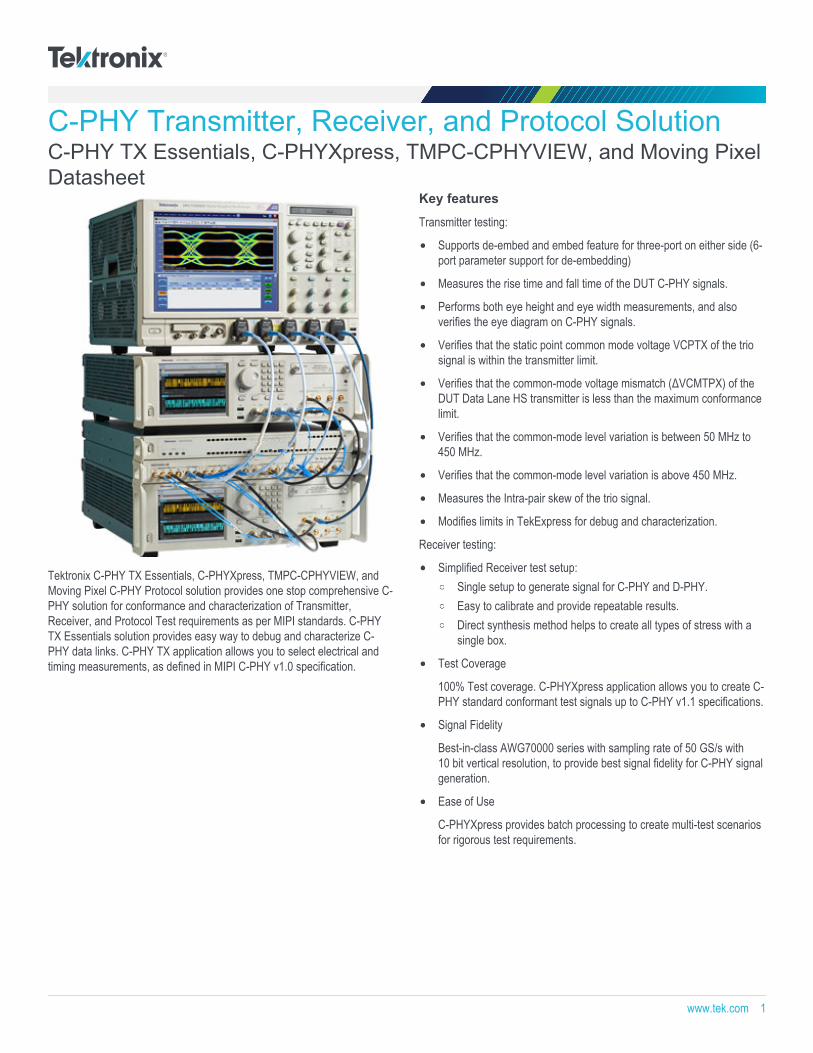
Tektronix C-PHY TX Essentials, C-PHYXpress, TMPC-CPHYVIEW, andMoving Pixel C-PHY Protocol solution provides one stop comprehensive C-PHY solution for conformance and characterization of Transmitter,Receiver, and Protocol Test requirements as per MIPI standards. C-PHYTX Essentials solution provides easy way to debug and characterize C-PHY data links. C-PHY TX application allows you to select electrical andtiming measurements, as defined in MIPI C-PHY v1.0 specification.
Key features
Transmitter testing:
Supports de-embed and embed feature for three-port on either side (6-port parameter support for de-embedding)
Measures the rise time and fall time of the DUT C-PHY signals.
Performs both eye height and eye width measurements, and alsoverifies the eye diagram on C-PHY signals.
Verifies that the static point common mode voltage VCPTX of the triosignal is within the transmitter limit.
Verifies that the common-mode voltage mismatch (ΔVCMTPX) of theDUT Data Lane HS transmitter is less than the maximum conformancelimit.
Verifies that the common-mode level variation is between 50 MHz to450 MHz.
Verifies that the common-mode level variation is above 450 MHz.
Measures the Intra-pair skew of the trio signal.
Modifies limits in TekExpress for debug and characterization.
Receiver testing:
Simplified Receiver test setup:Single setup to generate signal for C-PHY and D-PHY.Easy to calibrate and provide repeatable results.Direct synthesis method helps to create all types of stress with asingle box.
Test Coverage
100% Test coverage. C-PHYXpress application allows you to create C-PHY standard conformant test signals up to C-PHY v1.1 specifications.
Signal Fidelity
Best-in-class AWG70000 series with sampling rate of 50 GS/s with10 bit vertical resolution, to provide best signal fidelity for C-PHY signalgeneration.
Ease of Use
C-PHYXpress provides batch processing to create multi-test scenariosfor rigorous test requirements.
www.tek.com 1
Receiver conformance test and beyond:C-PHYXpress application provides a platform to create a widerange of stimuli to test the device beyond specification.Program Rise time and fall time of Data, Program ESC, LPCommand along with Programmable Stress as mentioned below:
HS mode stressorsRandom jitter and deterministic jitterEmbed insertion loss and de-emphasisDuty cycle distortionLP mode stressorseSpike and minimum pulse TMIN-RX
Set up/hold time toleranceReal-time skew control
Offline signal generation
C-PHYXpress application can work in offline mode or from PC, tocontrol the AWG remotely and generate C-PHY signals.
Moving Pixel C-PHY Protocol Generator and Decoder:
C-PHY Protocol Generator:
Stand-alone instrument with simplified setup and operation.
Supports MIPI C-PHY signaling up to 2.5 Gbps-per-lane, for 1 to4 lanes.
Provides independent channel and real time adjustments for voltageand skew.
Supports up to C-PHY v1.0, CSI2 v1.3, and DSI v1.2 protocols.
Provides automated video sequence construction according to theuser-defined frame timing.
Implements automatic image scaling, format conversion, and simpletest pattern generation.
Supports multi-message response capture using 4 KB buffer.
Includes DSC binary support; optional DSC image compressionsupport available.
Provides scripting and remote-control capability using .NET DLL.
Oscilloscope based C-PHY Protocol Decode:
Supports decode of single MIPI C-PHY lane up to 2.5 Gbps.
Decodes and displays CSI2 v1.2 or DSI2 v1.0 protocol packets, and C-PHY v1.1 signaling states/symbols.
DSI support does not include DSC, LPDT, BTA, or peripheralcommand decoding.
Cursors on oscilloscope linked to both directions of the decode window.
Provides search and display filtering capabilities.
Decodes, displays, and exports (under user control) captured videoframes.
Applications
Automotive camera and display
Mobile camera and display
Camera CMOS Image sensors
Display Driver ICs
Application processor for mobile devices
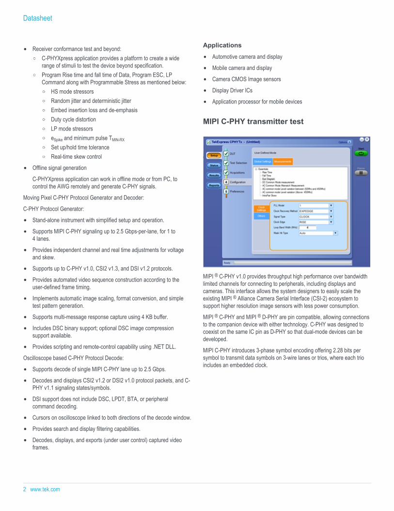
MIPI C-PHY transmitter test
MIPI ® C-PHY v1.0 provides throughput high performance over bandwidthlimited channels for connecting to peripherals, including displays andcameras. This interface allows the system designers to easily scale theexisting MIPI ® Alliance Camera Serial Interface (CSI-2) ecosystem tosupport higher resolution image sensors with less power consumption.
MIPI ® C-PHY and MIPI ® D-PHY are pin compatible, allowing connectionsto the companion device with either technology. C-PHY was designed tocoexist on the same IC pin as D-PHY so that dual-mode devices can bedeveloped.
MIPI C-PHY introduces 3-phase symbol encoding offering 2.28 bits persymbol to transmit data symbols on 3-wire lanes or trios, where each trioincludes an embedded clock.
Datasheet
2 www.tek.com
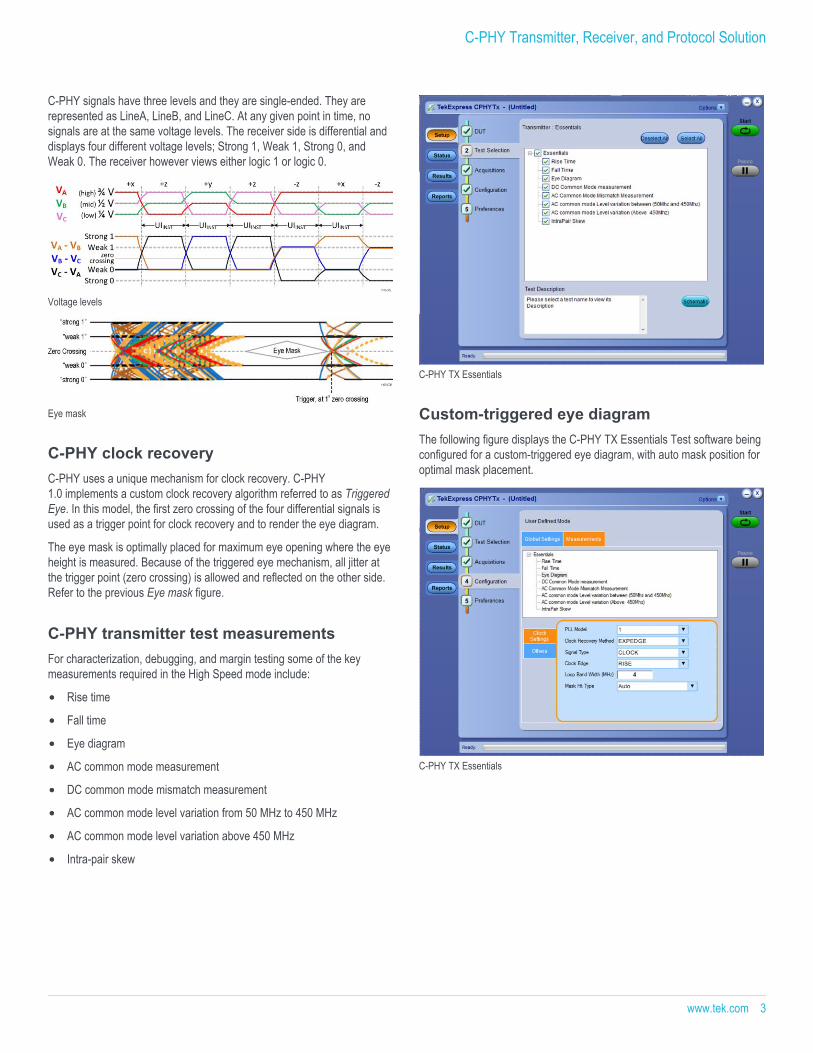
C-PHY signals have three levels and they are single-ended. They arerepresented as LineA, LineB, and LineC. At any given point in time, nosignals are at the same voltage levels. The receiver side is differential anddisplays four different voltage levels; Strong 1, Weak 1, Strong 0, andWeak 0. The receiver however views either logic 1 or logic 0.
Voltage levels
Eye mask
C-PHY clock recoveryC-PHY uses a unique mechanism for clock recovery. C-PHY1.0 implements a custom clock recovery algorithm referred to as TriggeredEye. In this model, the first zero crossing of the four differential signals isused as a trigger point for clock recovery and to render the eye diagram.
The eye mask is optimally placed for maximum eye opening where the eyeheight is measured. Because of the triggered eye mechanism, all jitter atthe trigger point (zero crossing) is allowed and reflected on the other side.Refer to the previous Eye mask figure.
C-PHY transmitter test measurementsFor characterization, debugging, and margin testing some of the keymeasurements required in the High Speed mode include:
Rise time
Fall time
Eye diagram
AC common mode measurement
DC common mode mismatch measurement
AC common mode level variation from 50 MHz to 450 MHz
AC common mode level variation above 450 MHz
Intra-pair skew
C-PHY TX Essentials
Custom-triggered eye diagramThe following figure displays the C-PHY TX Essentials Test software beingconfigured for a custom-triggered eye diagram, with auto mask position foroptimal mask placement.
C-PHY TX Essentials
C-PHY Transmitter, Receiver, and Protocol Solution
www.tek.com 3
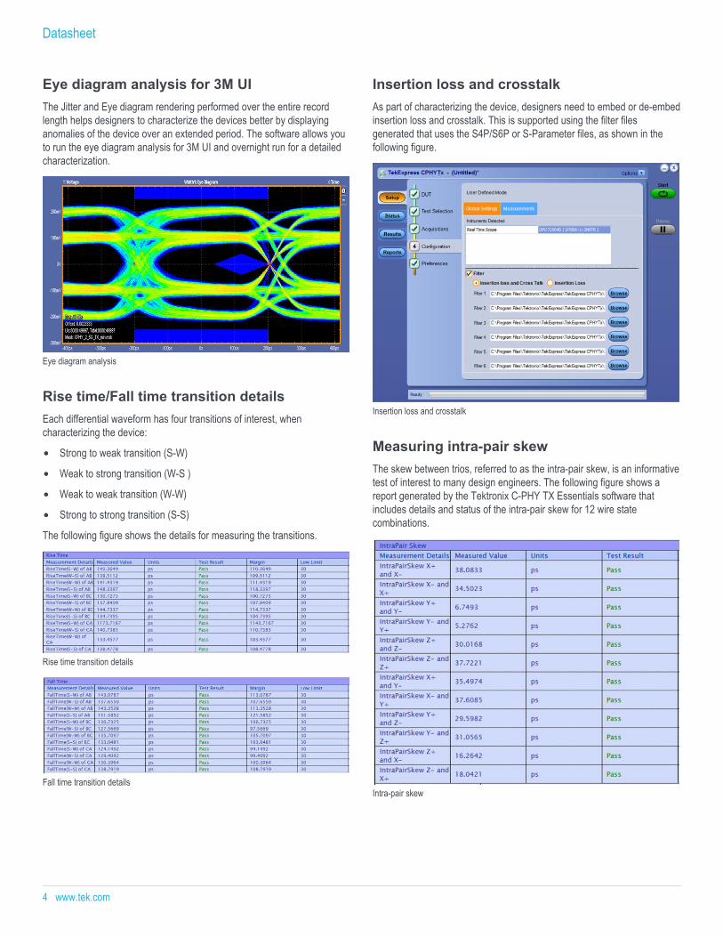
Eye diagram analysis for 3M UIThe Jitter and Eye diagram rendering performed over the entire recordlength helps designers to characterize the devices better by displayinganomalies of the device over an extended period. The software allows youto run the eye diagram analysis for 3M UI and overnight run for a detailedcharacterization.
Eye diagram analysis
Rise time/Fall time transition detailsEach differential waveform has four transitions of interest, whencharacterizing the device:
Strong to weak transition (S-W)
Weak to strong transition (W-S )
Weak to weak transition (W-W)
Strong to strong transition (S-S)
The following figure shows the details for measuring the transitions.
Rise time transition details
Fall time transition details
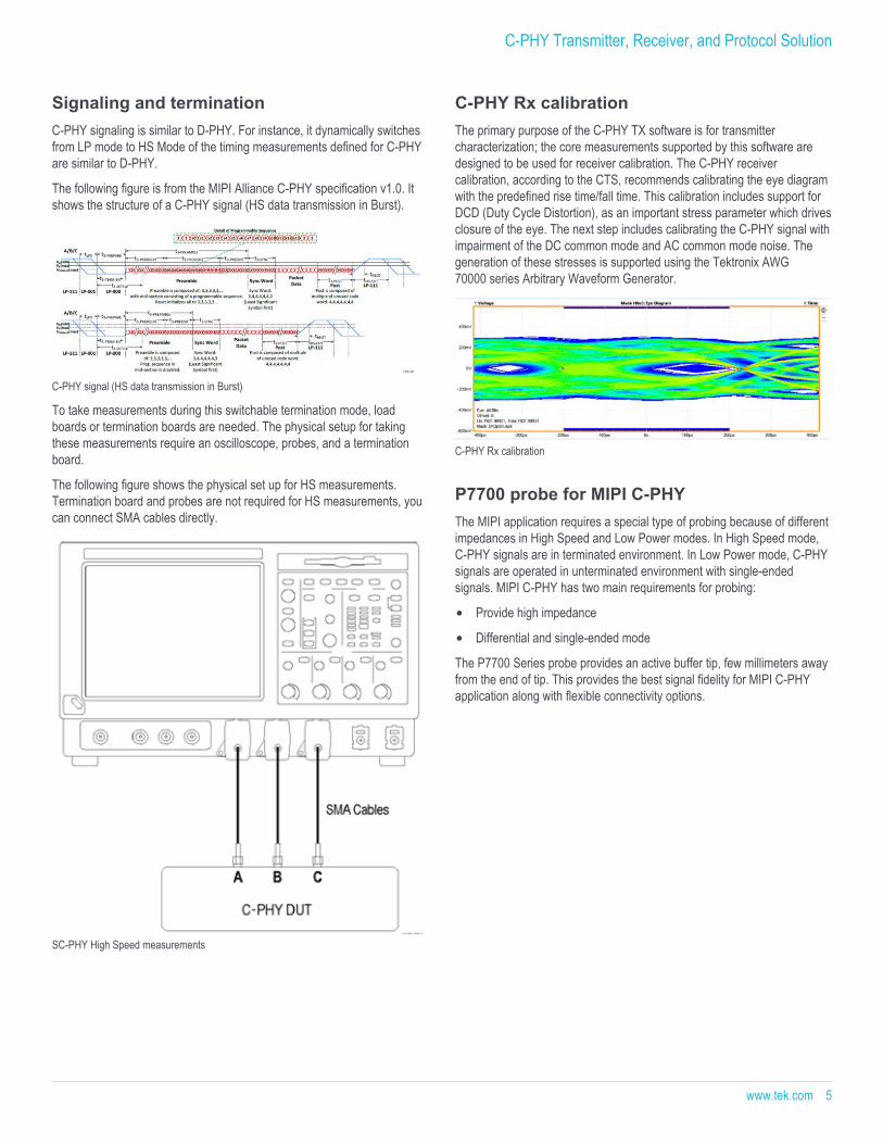
Insertion loss and crosstalkAs part of characterizing the device, designers need to embed or de-embedinsertion loss and crosstalk. This is supported using the filter filesgenerated that uses the S4P/S6P or S-Parameter files, as shown in thefollowing figure.
Insertion loss and crosstalk
Measuring intra-pair skewThe skew between trios, referred to as the intra-pair skew, is an informativetest of interest to many design engineers. The following figure shows areport generated by the Tektronix C-PHY TX Essentials software thatincludes details and status of the intra-pair skew for 12 wire statecombinations.
Intra-pair skew
Datasheet
4 www.tek.com
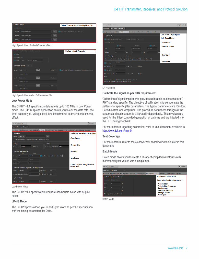
Signaling and terminationC-PHY signaling is similar to D-PHY. For instance, it dynamically switchesfrom LP mode to HS Mode of the timing measurements defined for C-PHYare similar to D-PHY.
The following figure is from the MIPI Alliance C-PHY specification v1.0. Itshows the structure of a C-PHY signal (HS data transmission in Burst).
C-PHY signal (HS data transmission in Burst)
To take measurements during this switchable termination mode, loadboards or termination boards are needed. The physical setup for takingthese measurements require an oscilloscope, probes, and a terminationboard.
The following figure shows the physical set up for HS measurements.Termination board and probes are not required for HS measurements, youcan connect SMA cables directly.
SC-PHY High Speed measurements
C-PHY Rx calibrationThe primary purpose of the C-PHY TX software is for transmittercharacterization; the core measurements supported by this software aredesigned to be used for receiver calibration. The C-PHY receivercalibration, according to the CTS, recommends calibrating the eye diagramwith the predefined rise time/fall time. This calibration includes support forDCD (Duty Cycle Distortion), as an important stress parameter which drivesclosure of the eye. The next step includes calibrating the C-PHY signal withimpairment of the DC common mode and AC common mode noise. Thegeneration of these stresses is supported using the Tektronix AWG70000 series Arbitrary Waveform Generator.
C-PHY Rx calibration
P7700 probe for MIPI C-PHYThe MIPI application requires a special type of probing because of differentimpedances in High Speed and Low Power modes. In High Speed mode,C-PHY signals are in terminated environment. In Low Power mode, C-PHYsignals are operated in unterminated environment with single-endedsignals. MIPI C-PHY has two main requirements for probing:
Provide high impedance
Differential and single-ended mode
The P7700 Series probe provides an active buffer tip, few millimeters awayfrom the end of tip. This provides the best signal fidelity for MIPI C-PHYapplication along with flexible connectivity options.
C-PHY Transmitter, Receiver, and Protocol Solution
www.tek.com 5

The TriMode probe helps to create differential, single-ended, and commonmode measurements accurately with the probe setup. This uniquecapability allows you to work more effectively and efficiently, switchingbetween differential, single-ended and common mode measurementswithout moving the probe's connection points.
P7700 Series TriMode probe
You can be confident in the signal fidelity of your measurements. Theinnovative new probe design uses SiGe Technology to provide thebandwidth and fidelity needed today and in the future.
The P7700 Series TriMode probe architecture provides:
An active buffer amplifier on the tips with the probe input only 3.2 mmfrom the input
Excellent step response and low insertion loss up to 20 GHz
Low-DUT loading with 100 kΩ (DC) and 0.4 pF (AC) performance
High CMRR
Low noise
Receiver testingThe C-PHYXpress plugin creates C-PHY signals for High Speed, HighSpeed Burst, and Low Power content with worst-case impaired inputsignals.
The Receiver test solution consists of the following steps:
Generate a test signal to emulate the transmitter, including channel andnoise impairments.
Calibrate the signal as per the CTS requirement.
Set up the Device for receiver test.
Determine the Bit Error Rate in the given test condition.
The C-PHYXpress application addresses the first two steps and aredescribed below:
Step 1: Generate a test signal to emulate the transmitter, includingchannel and noise impairments
The C-PHYXpress supports waveform generation for High Speed, LowPower, and Low Power-High Speed (LP-HS) mode as per C-PHYspecification v1.1.
High Speed mode: The C-PHY v1.1 specification data rate is up to3.5 Gbps in High Speed mode. As per the CTS, you need to emulate thechannel effect in High Speed mode. C-PHYXpress application allows you toedit the data rate, rise time, pattern type, voltage level, and impairments toemulate the channel effect.
High Speed Mode
In High Speed mode, you can add various channel effects such as:Periodic Jitter (Pj), Random Jitter (Rj), Dynamic Skew (DCD), Sine NoiseAmplitude, De-Emphasis, and S-Parameter file of Channel for Data signal.
High Speed with Jitter parameters
Datasheet
6 www.tek.com
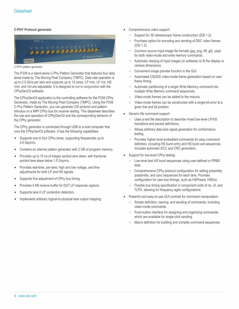
High Speed Jitter - Embed Channel effect
High Speed Jitter Mode - S-Parameter File
Low Power Mode
The C-PHY v1.1 specification data rate is up to 100 MHz in Low Powermode. The C-PHYXpress application allows you to edit the data rate, risetime, pattern type, voltage level, and impairments to emulate the channeleffect.
Low Power Mode
The C-PHY v1.1 specification requires Sine/Square noise with eSpikenoise.
LP-HS Mode:
The C-PHYXpress allows you to add Sync Word as per the specificationwith the timing parameters for Data.
LP-HS Mode
Calibrate the signal as per CTS requirement:
Calibration of signal impairments provides calibration routines that are C-PHY standard specific. The objective of calibration is to compensate thepatterns for specific jitter parameters. The typical parameters are Random,Periodic Jitter, and Amplitude. The procedure sequences through all thepatterns and each pattern is calibrated independently. These values areused for the Jitter- controlled generation of patterns and are injected intothe DUT during loopback.
For more details regarding calibration, refer to MOI document available inhttp://www.tek.com/mipi-0.
Test Coverage
For more details, refer to the Receiver test specification table later in thisdocument.
Batch Mode
Batch mode allows you to create a library of compiled waveforms withincremental jitter values with a single click.
Batch Mode
C-PHY Transmitter, Receiver, and Protocol Solution
www.tek.com 7
C-PHY Protocol generator
C-PHY pattern generator
The P339 is a stand-alone C-Phy Pattern Generator that features four datalanes made by The Moving Pixel Company (TMPC). Data rate operation isup to 2.5 Gb/s per wire and supports up to 12 wires. LP Voh, LP Vol, HSVoh, and Vol are adjustable. It is designed to run in conjunction with theCPhyGenCtl software.
The CPhyGenCtl application is the controlling software for the P339 CPhyGenerator, made by The Moving Pixel Company (TMPC). Using the P339C-Phy Pattern Generator, you can generate CSI protocol and patternstimulus on a MIPI CPhy bus for receiver testing. This datasheet describesthe use and operation of CPhyGenCtl and the corresponding behavior ofthe CPhy generator.
The CPhy generator is connected through USB to a host computer thatruns the CPhyGenCtl software. It has the following capabilities:
Supports one to four CPhy lanes, supporting frequencies up to2.6 Gsym/s.
Contains an internal pattern generator with 2 GB of program memory.
Provides up to 15 ns of integer symbol lane skew, with fractionalsymbol lane skew below 1.5 Gsym/s.
Provides real-time, per-lane, high and low voltage, and fine-adjustments for both LP and HS signals.
Supports fine adjustment of CPhy bus timing.
Provides 4 KB receive buffer for DUT LP response capture.
Supports lane 0 LP contention detection.
Implements arbitrary logical-to-physical lane output mapping.
Comprehensive video support:Support for 3D stereoscopic frame construction (DSI 1.2).Purchase option for encoding and sending of DSC video frames(DSI 1.2).Common source input image file formats (jpg, png, tiff, gif), usedfor both video-mode and write memory commands.Automatic resizing of input images (in software) to fit the display orcamera dimensions.Convenient image preview function in the GUI.Automated CSI/DSI video-mode frame generation based on userframe timing.Automatic partitioning of a single Write Memory command intomultiple Write Memory command sequences.Video-mode frames can be added to the macros.Video-mode frames can be constructed with a single-bit error at agiven line and bit position.
Generic file command support:Uses a text file description to describe mixed low-level LP/HStransitions and packet definitions.Allows arbitrary data lane signal generation for conformancetesting.Provides higher-level embedded commands for easy commanddefinition, including HS burst entry and HS burst exit sequences.Includes automatic ECC and CRC generation.
Support for low-level CPhy testing:Low-level test HS burst sequences using user-defined or PRBSdata.Comprehensive CPhy protocol configuration for setting preamble,postamble, and sync sequences for each lane. Providesconfiguration for user bus timings, such as HSPreare, HSExit.Flexible bus timing specification in component units of ns, UI, andTLPX, allowing for frequency agile configurations.
Powerful and easy-to-use GUI controls for command manipulation:Simple definition, naming, and sending of commands, includingvideo-mode commands.Push-button interface for assigning and organizing commands,which are available for single-click sending.Macro definition for building and complex command sequences.
Datasheet
8 www.tek.com
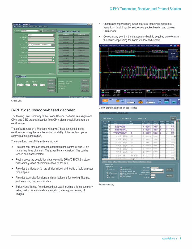
CPHY Gen
C-PHY oscilloscope-based decoderThe Moving Pixel Company CPhy Scope Decoder software is a single-laneCPhy and CSI2 protocol decoder from CPhy signal acquisitions from anoscilloscope.
The software runs on a Microsoft Windows 7 host connected to theoscilloscope, using the remote-control capability of the oscilloscope tocontrol real-time acquisition.
The main functions of this software include:
Provides real-time oscilloscope acquisition and control of one CPhylane using three channels. The saved binary waveform files can beloaded and disassembled.
Post-process the acquisition data to provide DPhy/DSI/CSI2 protocoldisassembly views of communication on the link.
Provides the views which are similar in look-and-feel to a logic analyzertype display.
Provides extensive functions and manipulations for viewing, filtering,and searching the captured data.
Builds video frames from decoded packets, including a frame summarylisting that provides statistics, navigation, viewing, and saving ofimages.
Checks and reports many types of errors, including illegal statetransitions, invalid symbol sequences, packet header, and payloadCRC errors.
Correlate any event in the disassembly back to acquired waveforms onthe oscilloscope using the zoom window and cursors.
C-PHY Signal Capture on an oscilloscope
Frame summary
C-PHY Transmitter, Receiver, and Protocol Solution
www.tek.com 9
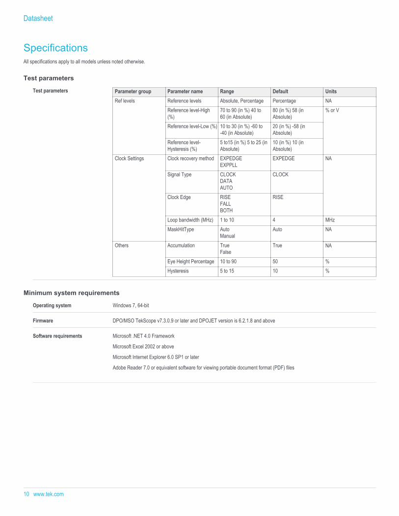
SpecificationsAll specifications apply to all models unless noted otherwise.
Test parameters
Test parameters Parameter group Parameter name Range Default UnitsRef levels Reference levels Absolute, Percentage Percentage NA
Reference level-High(%)
70 to 90 (in %) 40 to60 (in Absolute)
80 (in %) 58 (inAbsolute)
% or V
Reference level-Low (%) 10 to 30 (in %) -60 to-40 (in Absolute)
20 (in %) -58 (inAbsolute)
Reference level-Hysteresis (%)
5 to15 (in %) 5 to 25 (inAbsolute)
10 (in %) 10 (inAbsolute)
Clock Settings Clock recovery method EXPEDGEEXPPLL
EXPEDGE NA
Signal Type CLOCKDATAAUTO
CLOCK
Clock Edge RISEFALLBOTH
RISE
Loop bandwidth (MHz) 1 to 10 4 MHzMaskHitType Auto
ManualAuto NA
Others Accumulation TrueFalse
True NA
Eye Height Percentage 10 to 90 50 %Hysteresis 5 to 15 10 %
Minimum system requirements
Operating system Windows 7, 64-bit
Firmware DPO/MSO TekScope v7.3.0.9 or later and DPOJET version is 6.2.1.8 and above
Software requirements Microsoft .NET 4.0 Framework
Microsoft Excel 2002 or above
Microsoft Internet Explorer 6.0 SP1 or later
Adobe Reader 7.0 or equivalent software for viewing portable document format (PDF) files
Datasheet
10 www.tek.com
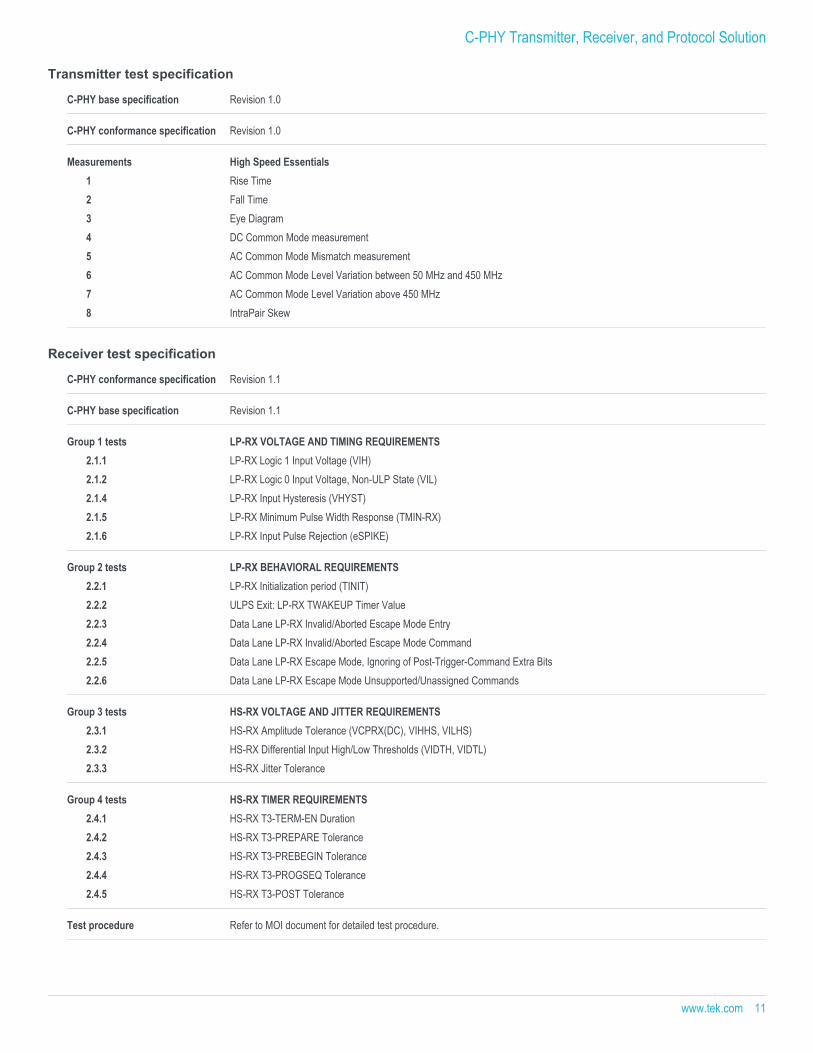
Transmitter test specification
C-PHY base specification Revision 1.0
C-PHY conformance specification Revision 1.0
Measurements High Speed Essentials1 Rise Time2 Fall Time3 Eye Diagram4 DC Common Mode measurement5 AC Common Mode Mismatch measurement6 AC Common Mode Level Variation between 50 MHz and 450 MHz7 AC Common Mode Level Variation above 450 MHz8 IntraPair Skew
Receiver test specification
C-PHY conformance specification Revision 1.1
C-PHY base specification Revision 1.1
Group 1 tests LP-RX VOLTAGE AND TIMING REQUIREMENTS2.1.1 LP-RX Logic 1 Input Voltage (VIH)2.1.2 LP-RX Logic 0 Input Voltage, Non-ULP State (VIL)2.1.4 LP-RX Input Hysteresis (VHYST)2.1.5 LP-RX Minimum Pulse Width Response (TMIN-RX)2.1.6 LP-RX Input Pulse Rejection (eSPIKE)
Group 2 tests LP-RX BEHAVIORAL REQUIREMENTS2.2.1 LP-RX Initialization period (TINIT)2.2.2 ULPS Exit: LP-RX TWAKEUP Timer Value2.2.3 Data Lane LP-RX Invalid/Aborted Escape Mode Entry2.2.4 Data Lane LP-RX Invalid/Aborted Escape Mode Command2.2.5 Data Lane LP-RX Escape Mode, Ignoring of Post-Trigger-Command Extra Bits2.2.6 Data Lane LP-RX Escape Mode Unsupported/Unassigned Commands
Group 3 tests HS-RX VOLTAGE AND JITTER REQUIREMENTS2.3.1 HS-RX Amplitude Tolerance (VCPRX(DC), VIHHS, VILHS)2.3.2 HS-RX Differential Input High/Low Thresholds (VIDTH, VIDTL)2.3.3 HS-RX Jitter Tolerance
Group 4 tests HS-RX TIMER REQUIREMENTS2.4.1 HS-RX T3-TERM-EN Duration2.4.2 HS-RX T3-PREPARE Tolerance2.4.3 HS-RX T3-PREBEGIN Tolerance2.4.4 HS-RX T3-PROGSEQ Tolerance2.4.5 HS-RX T3-POST Tolerance
Test procedure Refer to MOI document for detailed test procedure.
C-PHY Transmitter, Receiver, and Protocol Solution
www.tek.com 11
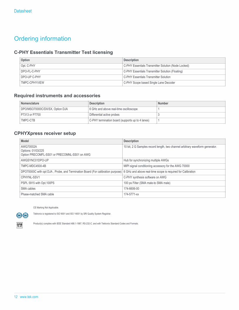
Ordering information
C-PHY Essentials Transmitter Test licensingOption DescriptionOpt. C-PHY C-PHY Essentials Transmitter Solution (Node Locked)DPO-FL-C-PHY C-PHY Essentials Transmitter Solution (Floating)DPO-UP C-PHY C-PHY Essentials Transmitter SolutionTMPC-CPHYVIEW C-PHY Scope based Single Lane Decoder
Required instruments and accessoriesNomenclature Description NumberDPO/MSO70000C/DX/SX, Option DJA 6 GHz and above real-time oscilloscope 1 P7313 or P7700 Differential active probes 3 TMPC-CTB C-PHY termination board (supports up to 4 lanes) 1
CPHYXpress receiver setupModel DescriptionAWG70002AOptions: 01/03/225 Option PRECOMFL-SS01 or PRECOMNL-SS01 on AWG
10 bit, 2 G Samples record length, two channel arbitrary waveform generator.
AWGSYNC01DPO-UP Hub for synchronizing multiple AWGsTMPC-MDC4500-4B MIPI signal conditioning accessory for the AWG 70000 DPO70000C with opt DJA , Probe, and Termination Board (For calibration purpose) 6 GHz and above real-time scope is required for CalibrationCPHYNL-SSV1 C-PHY synthesis software on AWGPSPL 5915 with Opt.100PS 100 ps Filter (SMA male-to SMA male)SMA cables 174-6606-00 Phase-matched SMA cable 174-5771-xx
CE Marking Not Applicable.
Tektronix is registered to ISO 9001 and ISO 14001 by SRI Quality System Registrar.
Product(s) complies with IEEE Standard 488.1-1987, RS-232-C, and with Tektronix Standard Codes and Formats.
Datasheet
12 www.tek.com

C-PHY Transmitter, Receiver, and Protocol Solution
www.tek.com 13
Datasheet
ASEAN / Australasia (65) 6356 3900 Austria 00800 2255 4835* Balkans, Israel, South Africa and other ISE Countries +41 52 675 3777 Belgium 00800 2255 4835* Brazil +55 (11) 3759 7627 Canada 1 800 833 9200 Central East Europe and the Baltics +41 52 675 3777 Central Europe & Greece +41 52 675 3777 Denmark +45 80 88 1401 Finland +41 52 675 3777 France 00800 2255 4835* Germany 00800 2255 4835*Hong Kong 400 820 5835 India 000 800 650 1835 Italy 00800 2255 4835*Japan 81 (3) 6714 3086 Luxembourg +41 52 675 3777 Mexico, Central/South America & Caribbean 52 (55) 56 04 50 90 Middle East, Asia, and North Africa +41 52 675 3777 The Netherlands 00800 2255 4835* Norway 800 16098 People's Republic of China 400 820 5835 Poland +41 52 675 3777 Portugal 80 08 12370 Republic of Korea +822 6917 5084, 822 6917 5080 Russia & CIS +7 (495) 6647564 South Africa +41 52 675 3777 Spain 00800 2255 4835* Sweden 00800 2255 4835* Switzerland 00800 2255 4835*Taiwan 886 (2) 2656 6688 United Kingdom & Ireland 00800 2255 4835* USA 1 800 833 9200
* European toll-free number. If not accessible, call: +41 52 675 3777
For Further Information. Tektronix maintains a comprehensive, constantly expanding collection of application notes, technical briefs and other resources to help engineers working on the cutting edge of technology. Please visit www.tek.com.
Copyright © Tektronix, Inc. All rights reserved. Tektronix products are covered by U.S. and foreign patents, issued and pending. Information in this publication supersedes that in all previously published material. Specification andprice change privileges reserved. TEKTRONIX and TEK are registered trademarks of Tektronix, Inc. All other trade names referenced are the service marks, trademarks, or registered trademarks of their respective companies.
07 Feb 2017 61W-60145-1
www.tek.com