c arXiv:astro-ph/0605500v1 19 May 2006
25
arXiv:astro-ph/0605500v1 19 May 2006 The ZEPLIN-III dark matter detector: instrument design, manufacture and commissioning D. Yu. Akimov a , G. J. Alner b , H. M. Ara´ ujo c,b , A. Bewick c , C. Bungau c,b , A. A. Burenkov a , M. J. Carson d , V. Chepel e , D. Cline f , D. Davidge c , J. C. Davies d , E. Daw d , J. Dawson c , T. Durkin b , B. Edwards c,b , T. Gamble d , C. Ghag g , R. J. Hollingworth d , A. S. Howard c , W. G. Jones c , M. Joshi c , J. Kirkpatrick d , A. Kovalenko a , V. A. Kudryavtsev d , I. S. Kuznetsov a , T. Lawson d , V. N. Lebedenko c , J. D. Lewin b , P. Lightfoot d , A. Lindote e , I. Liubarsky c , M. I. Lopes e , R. L¨ uscher b , J. E. McMillan d , B. Morgan d , D. Muna d , A. S. Murphy g , F. Neves e , G. G. Nicklin d , S. M. Paling d , D. Muna d , J. Pinto da Cunha e , S. J. S. Plank g , R. Preece b , J. J. Quenby c , M. Robinson d , C. Silva e , V. N. Solovov e , N. J. T. Smith b , P. F. Smith b , N. J. C. Spooner d , V. Stekhanov a , T. J. Sumner c,∗ , C. Thorne c , D. R. Tovey d , E. Tziaferi d , R. J. Walker c , H. Wang f , J. White h & F. Wolfs i a Institute for Theoretical and Experimental Physics, Moscow, Russia b Particle Physics Department, Rutherford Appleton Laboratory, Chilton, UK c Blackett Laboratory, Imperial College London, UK d Physics and Astronomy Department, University of Sheffield, UK e LIP–Coimbra & Department of Physics of the University of Coimbra, Portugal f Department of Physics & Astronomy, University of California, Los Angeles, USA g School of Physics, University of Edinburgh, UK h Texas A&M University, USA i University of Rochester, New York, USA Preprint submitted to Elsevier Science 4 February 2008
Transcript of c arXiv:astro-ph/0605500v1 19 May 2006

arX
iv:a
stro
-ph/
0605
500v
1 1
9 M
ay 2
006
The ZEPLIN-III dark matter detector:
instrument design, manufacture and
commissioning
D. Yu. Akimov a, G. J. Alner b, H. M. Araujo c,b, A. Bewick c,
C. Bungau c,b, A. A. Burenkov a, M. J. Carson d, V. Chepel e,D. Cline f, D. Davidge c, J. C. Davies d, E. Daw d, J. Dawson c,
T. Durkin b, B. Edwards c,b, T. Gamble d, C. Ghag g,
R. J. Hollingworth d, A. S. Howard c, W. G. Jones c, M. Joshi c,J. Kirkpatrick d, A. Kovalenko a, V. A. Kudryavtsev d,
I. S. Kuznetsov a, T. Lawson d, V. N. Lebedenko c, J. D. Lewin b,P. Lightfoot d, A. Lindote e, I. Liubarsky c, M. I. Lopes e,
R. Luscher b, J. E. McMillan d, B. Morgan d, D. Muna d,A. S. Murphy g, F. Neves e, G. G. Nicklin d, S. M. Paling d,
D. Muna d, J. Pinto da Cunha e, S. J. S. Plank g, R. Preece b,
J. J. Quenby c, M. Robinson d, C. Silva e, V. N. Solovov e,N. J. T. Smith b, P. F. Smith b, N. J. C. Spooner d,
V. Stekhanov a, T. J. Sumner c,∗, C. Thorne c, D. R. Tovey d,E. Tziaferi d, R. J. Walker c, H. Wang f, J. White h & F. Wolfs i
aInstitute for Theoretical and Experimental Physics, Moscow, Russia
bParticle Physics Department, Rutherford Appleton Laboratory, Chilton, UK
cBlackett Laboratory, Imperial College London, UK
dPhysics and Astronomy Department, University of Sheffield, UK
eLIP–Coimbra & Department of Physics of the University of Coimbra, Portugal
fDepartment of Physics & Astronomy, University of California, Los Angeles, USA
gSchool of Physics, University of Edinburgh, UK
hTexas A&M University, USA
iUniversity of Rochester, New York, USA
Preprint submitted to Elsevier Science 4 February 2008

Abstract
We present details of the technical design and manufacture of the ZEPLIN-III darkmatter experiment. ZEPLIN-III is a two-phase xenon detector which measures boththe scintillation light and the ionisation charge generated in the liquid by interact-ing particles and radiation. The instrument design is driven by both the physicsrequirements and by the technology requirements surrounding the use of liquidxenon. These include considerations of key performance parameters, such as theefficiency of scintillation light collection, restrictions placed on the use of materialsto control the inherent radioactivity levels, attainment of high vacuum levels andchemical contamination control. The successful solution has involved a number ofnovel design and manufacturing features which will be of specific use to future gen-erations of direct dark matter search experiments as they struggle with similar andprogressively more demanding requirements.
Key words: ZEPLIN-III, dark matter, liquid xenon, radiation detectors, WIMPsPACS: code, code
1 Introduction
ZEPLIN-III is a two-phase (liquid/gas) xenon detector developed and built bythe ZEPLIN Collaboration, 1 which will try to identify and measure galacticdark matter in the form of Weakly Interacting Massive Particles, or WIMPs[1,2]. Upon completion of physics testing now underway at Imperial College,the system will join the ZEPLIN-II [3] and DRIFT-IIa [4] experiments alreadyoperating 1100 m underground in our laboratory at the Boulby mine (NorthYorkshire, UK).
Two-phase emission detectors based on the noble gases date back severaldecades [5]. In last decade, this technology has gained a new momentum inview of increasing interest for searching rare events, WIMPs in particular,requiring both large detection masses and high discrimination against back-ground. In its previous work, the ZEPLIN Collaboration has explored the po-tential of high-field xenon systems to enhance sensitivity and background dis-crimination [6,7,8]. The operating principle relies on different particle species
∗ Corresponding author; address: Astrophysics Group, Blackett Laboratory, Impe-rial College London, SW7 2BW, UK
Email address: [email protected] (T. J. Sumner).1 Edinburgh University, Imperial College London, ITEP-Moscow, LIP-Coimbra,Rochester University, CCLRC Rutherford Appleton Laboratory, Sheffield Univer-sity, Texas A&M, UCLA.
2

generating different amounts of vacuum ultra-violet (VUV) scintillation lightand ionisation charge in liquid xenon (LXe). The ratio between these two sig-nal channels provides a powerful technique to discriminate between electronand nuclear recoil interactions. WIMPs are expected to scatter elastically offXe atoms, much like neutrons, and the recoiling nucleus will produce a differ-ent signature to γ-ray interactions and other sources of electron recoils.
WIMP detectors differ from more traditional detectors of nuclear radiation inthat they require: i) extremely low radioactive and cosmic-ray backgrounds,addressed by the use of radio-pure materials and operation deep underground;ii) excellent discrimination of the remaining background events, especiallyfor electron recoils; iii) a low energy threshold for nuclear recoils, since thekinematics of WIMP-nucleus scattering results in a very soft recoil spectrum(.100 keV).
Monte Carlo simulations [9,10] were essential in key areas to inform the designof the instrument. Acceptable levels of trace contamination must be set for alldetector materials, requiring simulations of internal and external backgroundsexpected from each component. Cosmic-ray-induced backgrounds also needcareful calculation, since experimental measurements would require nothingshort of a dedicated WIMP detector. These simulations establish the residualelectron/photon and neutron event rates and spectra. Detailed detector sim-ulations leading to predicted data timelines can be used to find the level ofdiscrimination and energy threshold which can realistically be achieved. Feed-back from this process into the design process has been essential for ZEPLINIII. In addition, the data produced by two-phase detectors are often com-plex, and particular simulations are required to help extract actual physicsparameters. Finally, realistic datasets help with planning the data acquisitionelectronics and the data analysis software.
In this paper we describe the instrument design philosophy, the engineeringdesign solutions and the manufacturing processes adopted. In a separate paper[11] we present full performance Monte Carlo simulations for the final, as built,instrument.
2 The ZEPLIN-III instrument
There are four important design requirements for a dark matter detector: alow energy threshold, good particle discrimination, 3-D position reconstructionand a low background within the fiducial volume. The ZEPLIN III approach,as shown in figure 1, tries to push the boundaries of the two-phase xenontechnique to simultaneously achieve the best performance possible in thesefour aspects.
3

Fig. 1. Cross-sectional views of the ZEPLIN III instrument showing the key systemdesign concepts. The rendered CAD representation shows the copper parts.
ZEPLIN-III achieves a low threshold for the primary scintillation by placingits photo-detectors, photomultipliers (PMTs) in the liquid phase and by usinga flat planar geometry. Using PMTs in the liquid removes two interfaces, bothwith large refractive index mismatches and puts in an additional interface atwhich total internal reflection also works to improve the light collection for theprimary scintillation. The planar geometry gives a large solid angle acceptanceand lessens the dependance on surface reflectivities. A low threshold for theelectroluminescence from the gas phase which provides the secondary signalis achieved by using a high electric field in the gas region to produce highlevels of photon emission per electron emitted from the surface and by usingrefraction at the liquid surface to produce a ‘focusing’ effect for the light ontothe immersed PMT array.
ZEPLIN-III achieves good particle discrimination between the nuclear recoilsignals expected from WIMPs and the electron recoils from photon back-grounds by employing a two-phase design which allows both scintillation andionisation to be measured for each event. The ratio of these two signals de-pends on the particle species. The effectiveness of this discrimination dependson the width and separation of the distributions for each species. It turns out[12] that the discrimination is improved by working at moderate electric fieldswhich increases the separation between the two distributions and improves thestatistical uncertainties of the ionisation signal. Some discrimination againstnuclear recoil signals from neutron elastic scattering is obtained by havinggood 3-D position reconstruction which can identify the multiple scattering
4

expected from the much higher cross-sections for neutron scattering than forWIMP scattering. Efficient measurement of the ionisation relies on achievinga long lifetime against trapping for free electrons in the liquid. This requiresultra-pure xenon as free from electronegative impurities as possible. The tar-get volumes must be constructed as high vacuum vessels and a dedicated gaspurification system is needed.
ZEPLIN-III achieves good 3-D position reconstruction by using an array of 312” diameter photomultipliers. These provide sub-cm 2-D spatial resolution inthe horizontal r, θ plane. Resolution in the z co-ordinate at the ∼ 50 µm levelis obtained from the timing between the primary and secondary scintillationsignals.
ZEPLIN-III achieves a low background partly by operation underground andpartly by using a very restricted range of materials for its construction. Al-though the PMTs are the largest specific contributors to the background bud-get it is important that careful attention is paid to all materials used as theseexceed the PMT mass by two orders of magnitude. In addition it is planned toeventually replace the PMTs by low-background versions which are currentlyin development.
In the following sections we detail the design and manufacture of the individ-ual parts of the ZEPLIN III experiment. These include the target volume, thecooling system, the outer vacuum jacket, the gas handling system, includingthe safety reservoirs, and the data acquisition system. In the final section weprovide data from surface commissioning tests which validate the key perfor-mance parameters for ZEPLIN III
3 The target volume
The detailed design of the inner components within the target volume is shownin figure 2.
3.1 The PMT array
Inside the xenon vessel is the array of 31 PMTs, immersed in the liquid phase,looking up to a ≃40 mm-thick liquid xenon layer on top of which is a 5 mmxenon gas gap. The figure shows a cross-sectional view through a centre linepassing through 5 of the 52 mm diameter PMTs. The others are arranged ina hexagonal close-packed array with a pitch spacing of 54 mm. A pure copper‘screen’ has an array of 53 mm holes into which the PMTs fit. This provides
5

Fig. 2. Cross-sectional assembly drawing of the internal chamber volume of ZEPLINIII.
both light screening and electrical isolation between the PMTs. It has anouter diameter of 340 mm and a height of 128 mm. For ease of manufacturethe total height of the ‘screen’ was made in four sections. Each PMT holethrough the copper ‘screen’ has a diameter of 53mm giving a 1 mm wallminimum thickness between each PMT. Two techniques were used to producesuch thin wall section through such a thickness of copper; wire erosion andboring. Both worked but the boring produced a better surface finish. Sittingdirectly on top of the ‘screens’ is another copper disc with holes in it. Thistime the thickness is 7 mm and the holes are finished with highly polishedconical sections to improve the light collection; this plate is hence referred toas the ‘PMT mirror’.
Each PMT has 15 pins to which connections must be made (12 dynodes, anode,cathode and focus). However it would be impractical to bring all 465 connec-tions out through individual UHV electrical feeds through the bottom thickcopper flange. Instead all the PMTs are run from a common high voltage sup-ply and dynode distribution system which reduces the amount of feedthroughsto just 47. The corresponding dynode pins on each PMT are connected to-gether using a stack of 16 thin copper plates, held apart with small quartzspacers, below the PMT array. Each 2mm thick plate has a different patternof holes (see figure 3) allowing connection to each pin in turn whilst the otherspass through with clearance. Connections between the copper plates and thePMT contacts were done by first cold welding a pin into the copper plate andthen using spring loaded tubes to join the two pins together (see figure 4).The pins used in the copper plates were made in copper with a gold coatingand these were inserted into tight fitting holes in the plates using a drill press.The spring contacts were made from stainless steel tubing with reduced wall
6

sections and slots. These contacts provide enough friction for retention of thePMT against buoyancy forces during immersion in liquid xenon. Connectionbetween each plate and its single UHV coaxial feedthrough was again madeby a direct spring loaded tube but with the addition of gold-plated copperwires with silver-plated copper adaptors to provide the extensions betweenend contacts. The anode connection from each PMT is brought out separatelyon a dedicated coaxial UHV feedthrough in a similar way. The specific ar-rangement of the 16 copper plates can be seen in figure 4. The upper andlower plates are connected to ground. The second lowest plate is connectedto the PMT cathodes, the next 11 are connected to dynodes 1 to 11 in turn.Above that there is then another grounded plate and between this and the topground plate is dynode 12. The two grounded plates either side of the dynode12 plate deliberately provide both extra capacitance to ground for that dyn-ode and prevent cross-coupling with other connections. Copper tubes provideshielding along the run of each anode output connection. Shielded cables passacross the outer vacuum jacket space to connectors in its base plate. A singleexternal voltage divider chain is used to provide all the common dynode volt-ages. To ensure reasonably well matched gains when running from a commonHV supply, PMTs were procured with gains within prescribed limits. Onceselected the batch of 35 PMTs (ETL D730/9829Q) was tested and calibratedat low temperature with Xe scintillation UV light prior to installation in thedetector [13]. The PMTs were customised specifically for ZEPLIN III in twoways: firstly a conductive pattern of so-called ‘fingers’ was deposited on theinside of the window to avoid saturation at high count rates, and secondlyto provide a modified pin-out arrangement to facilitate the use of the copperinterconnection plates. The PMTs are operated with the cathode at groundpotential.
3.2 The electric field
Proper operation in two-phase mode requires that there be a sufficiently highelectric field in three distinct regions. In the active volume of the detector theelectric field helps to separate ionisation charge released from the track of theinteracting particle before it can recombine. This field must be directed suchthat the electrons start ‘drifting’ towards the liquid surface. Hence the fieldin this first region is called the ‘drift’ field. The second critical region is atthe liquid/gas interface. Here the field in the liquid must be high enough toefficiently extract the electrons into the gas phase. This not only increases thesignal strength but also prevents charge build-up at the surface. This field iscalled the ‘extraction’ field. Finally in the gas phase the field must be highenough for the accelerated electrons to produce excitation in the gas atoms.The excited atoms then form excited dimers followed by dissociative radiativeemission in the usual way, which produces the signal seen by the PMTs. This
7

Fig. 3. The 16 2-mm copper plates used to make the internal PMT dynode inter-connections.
last field is called the ‘electroluminescence’ field. These three fields can eitherbe produced by setting up a segmented electrode structure producing distinctregions, as is done in ZEPLIN II [14], or, as in the case of ZEPLIN III, asingle pair of outer electrodes can be used to produce all three at once. Theadvantage of the latter is the absence of any physical electrode structure in theliquid which could then be a source of background and/or feedback. Howeverit does mean that a single much higher individual voltage is required and thefields can not be controlled independently. The two electrodes used are the
8

PMT Anode Pin
PMT Dynode 12 Pin
PMT Screen
S.S. Tube
Copper Gold Plated Wires
Copper Silver PlatedSlotted Pins
PMT Cathode Pin
Copper Silver Plated Slotted Adapter
Fig. 4. Various spring loaded contacts used to connect the PMT pins to the copperplates.
solid flat plate (‘anode mirror’) above the gas gap and a wire plane (‘cathodegrid’) 40 mm below it in the liquid. The 8-mm top plate is made from copperand its bottom surface has been lapped using optical techniques and left highlypolished. Up to 40 kV can be applied between the two ‘electrodes’.
A second wire grid (‘PMT grid’) is located 5 mm below the cathode grid andjust above the PMT array. This defines a reverse field region just above thePMTs which suppresses secondary signals from low-energy background pho-tons from the PMTs and also helps isolate the internal PMT photocathodefields from the external high electric field. The diameter of the electrode struc-ture is ∼ 40 cm, whilst that of the PMT array is 34 cm. The fiducial volumewill be defined by a combination of primary to secondary timing and positionrecovery from the PMT hit pattern, and it will be well inside the PMT arraydiameter. This ensures that the electric field will be very uniform over thefiducial volume region. Field and electron trajectory simulations, producedusing ANSYS [15], are shown in figure 5.
The stainless-steel wire grids were strung from continuous lengths of 100 µmdiameter wire wound around copper formers. The position of each wire wascontrolled by slots machined into the formers (see figure 6). The wires weretensioned using two techniques. Firstly the formers were elastically deformedwhilst the wire was wound and secondly the winding jig tensioned the wireas it was wound. Once the grid winding was complete the wire was anchoredand the formers were then released from their restraining jigs.
9

Fig. 5. Electric field distribution within the target volume as computed using AN-SYS [15]. On the right is shown an expanded view of the drift paths of electronsnear the right-hand gap between the two electrodes.
Some consideration was given to whether the anode mirror should be coated toenhance its reflectivity. The performance of polished copper is quite uncertainat VUV wavelengths, depending on the surface finish, oxidation state andpossible LXe condensation onto the cold surface in the gas phase. Only asingle measurement has been found, indicating R=25% for normal incidencefor a clean-cut surface [16]. However the simplicity of leaving this surface as is,the uncertainty of using coatings in a high-field application and the desire notto compromise the spatial reconstruction argued for not using any coating.
Fig. 6. On the left are the copper formers for the wire grids. The inset detail showsan expanded view in which the slots cut to control to wire positioning can be seen.On the right is a view of the assembled PMT array in which the PMT grid can beseen.
3.3 The xenon transport system
Two copper access pipes are included for movement of xenon in and out of thetarget vessel (see figure 7). One surfaces above the liquid level in an unconfinedvolume as is used as a ‘Gas Inlet’. The second has a double tube structure withan open ended inner pipe connected directly to the main xenon liquid volume,and an outer pipe which vents to the outside through the ‘LXe Outlet’. Theouter pipe is sealed at the top and the inner opens above the liquid surfaceand essentially allows a ‘syphon’ action during emptying. Transfer of xenon inand out of the target vessel is independent of the cooling system.
10

LXe VesselBase Flange
Copper Rings
LXe Vessel Shell
Anode Mirror
LXe Vapour P1
LXe Outlet
Gas Xe Inlet
P2
LXe
Fig. 7. Arrangement of the pipework used for xenon transfer in and out of the targetvessel.
3.4 The target vessel
The containment vessel for the xenon target must perform as both a highvacuum vessel, for purity reasons, and a pressure vessel for safety reasons.The pressure vessel design was done following the relevant British Standard(BS5500:1997). This safety standard dictates the cylindrical wall, dome andbottom flange thicknesses which are dependent on the material and processesused. The vessel was required to be certified to 6 bar absolute. The material ofchoice was determined by requiring the product of total mass times radioactivecontent be a minimum. Added to this prime requirement was then the needfor the material to be suitable for manufacture of the vessel. OFHC coppertype C103 was selected. This required 4mm wall thickness on the cylindri-cal sections, 3mm for the spun domes and 25mm for the flat bottom flange.To minimise the likelihood of inclusion of any impurities electron-beam weld-ing was used throughout and the number of welds was kept to a minimum.
11

In particular the cylindrical section was rolled in one piece. Stainless steelparts were used for some specialist components which would have been verydifficult to make out of copper, such as vacuum knife edge flanges and vac-uum HV feedthroughs for which commercial parts were used. Where necessarythese stainless parts were also electron-beam welded to the copper. Weldingtechniques adapted to our requirements were developed by The Welding Insti-tute, UK[17], in close cooperation with us. This included setting the weldingparameters and optimising the structural/thermal design of the weld joints.All safety critical welding was done by certified processes and copper witnessplates were used to ensure proper and complete breakthrough as all welds wererequired to show full-depth penetration. Special jigging was required to holdall seams for welding securely in place during the process. On completion alljoints were leak-tested down to the level of ∼ 10−10 mbar.l.s−1.
The electrical feedthroughs for the PMT dynode connections were fitted inwith screw threads with thick indium coated onto them using an ultrasonicsoldering iron. The demountable vacuum seal between the cylindrical sectionand the bottom flange was done using a stainless steel gasket with double knifeedges and an indium wire at both copper surfaces (see figure 8). All copper
S.S. Gasket Cu SpacerIndium Wires
Vessel Base Flange
Vessel Shell Flange
I
II
I
II
Assembling Before Sealing
Assembling After SealingFig. 8. Vacuum seal between the cylindrical wall section and the bottom flangebefore (I) and after (II) sealing.
parts were cleaned, starting with a coarse hand polishing with stainless wirewool, a fine polishing with copper wire wool, an ultrasonic bath using 2%CITRANOX [18] in de-ionised water and a high-pressure wash using purewater. The polishing phase was done using a powered rotation table specially
12
built for the purpose and polishing was always applied along the line of existingmachining marks.
4 The cooling system
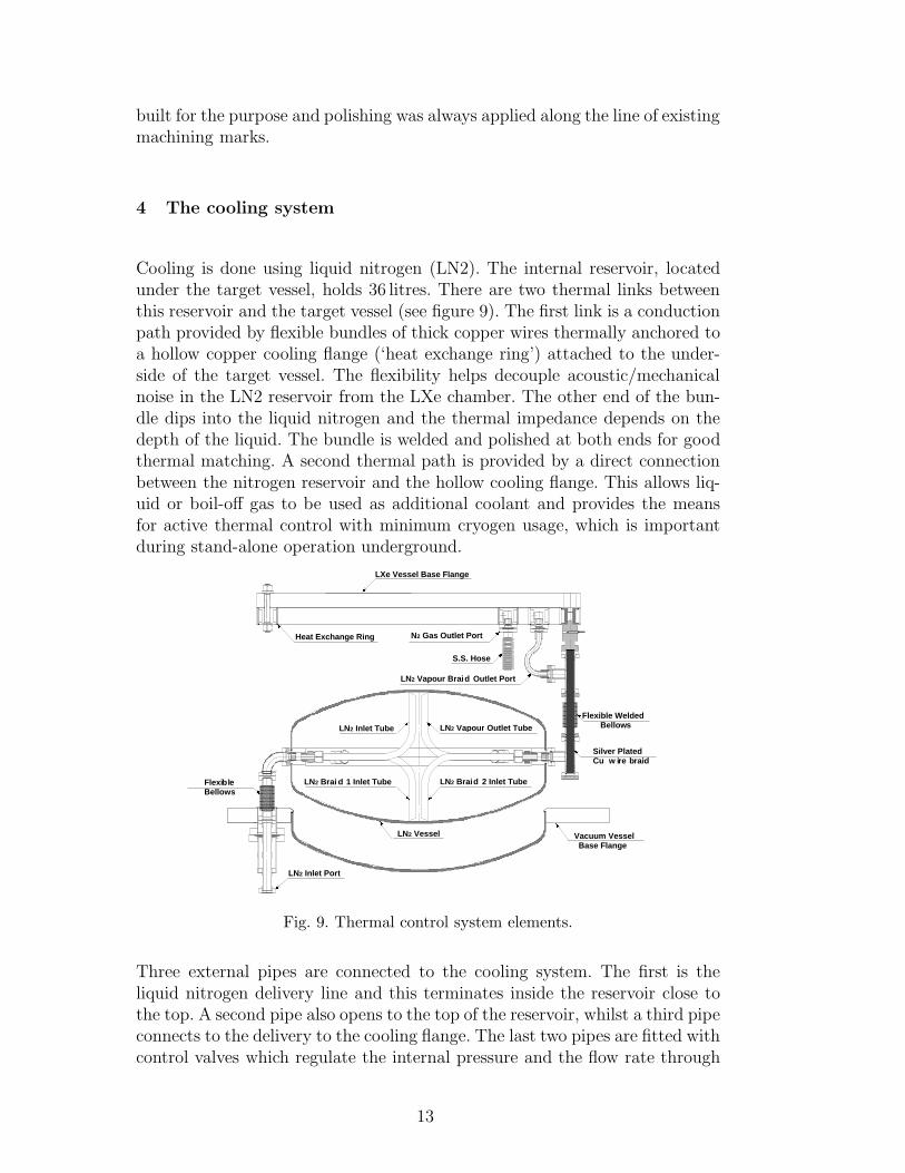
Cooling is done using liquid nitrogen (LN2). The internal reservoir, locatedunder the target vessel, holds 36 litres. There are two thermal links betweenthis reservoir and the target vessel (see figure 9). The first link is a conductionpath provided by flexible bundles of thick copper wires thermally anchored toa hollow copper cooling flange (‘heat exchange ring’) attached to the under-side of the target vessel. The flexibility helps decouple acoustic/mechanicalnoise in the LN2 reservoir from the LXe chamber. The other end of the bun-dle dips into the liquid nitrogen and the thermal impedance depends on thedepth of the liquid. The bundle is welded and polished at both ends for goodthermal matching. A second thermal path is provided by a direct connectionbetween the nitrogen reservoir and the hollow cooling flange. This allows liq-uid or boil-off gas to be used as additional coolant and provides the meansfor active thermal control with minimum cryogen usage, which is importantduring stand-alone operation underground.
Silver Plated Cu w ire braid
LXe Vessel Base Flange
Heat Exchange Ring N2 Gas Outlet Port
LN2 Vapour Braid Outlet Port
S.S. Hose
Flexible Welded Bellows
Flexible Bellows
Vacuum Vessel Base Flange
LN2 Vessel
LN2 Brai d 1 Inlet Tube LN2 Braid 2 Inlet Tube
LN2 Inlet Tube LN2 Vapour Outlet Tube
LN2 Inlet Port
Fig. 9. Thermal control system elements.
Three external pipes are connected to the cooling system. The first is theliquid nitrogen delivery line and this terminates inside the reservoir close tothe top. A second pipe also opens to the top of the reservoir, whilst a third pipeconnects to the delivery to the cooling flange. The last two pipes are fitted withcontrol valves which regulate the internal pressure and the flow rate through
13

the hollow cooling flange. During initial cool-down the flow through the coolingflange is increased to allow bulk liquid flow into it. Once cold, the gas flowthrough the cooling flange provides a fine temperature control mechanismwhilst the copper cable bundles provide the main thermal link balancing theaverage heat load. The heat load is reduced by the use of thermal insulationaround both the target vessel and the nitrogen chamber (see figure 10). Thenominal operating temperature is around −100oC and the heat load is, asexpected, ∼ 40 W, giving a design hold-time between refills of ∼2 days.
Fig. 10. The assembled instrument without its vacuum jacket giving a view of thetarget vessel (top) and liquid nitrogen reservoir both covered with thermal insula-tion.
14

5 The outer vacuum jacket
The design principles for the vacuum jacket were much the same as for thetarget vessel, except that the pressure rating was reduced to 4.3 bar absolute.The safety standard for pressure vessels dictated the material thicknesses andprocess standards and the same attention to background and cleanliness wasimposed. Hence OFHC copper was used, with electron beam welding andminimisation of the number of seams; the cylindrical section of this largervessel was also made from just one rolled plate. The bottom flange has anincluded domed section and the vacuum seals were all done in the same wayas for the target vessel. Figure 11 shows the underside view of the bottomflange.
Fig. 11. The bottom flange of the vacuum jacket showing the inner domed sectionand the arrangement of feedthroughs and ports around the outer skirt.
6 The gas purification system and safety reservoirs
Figure 12 shows a schematic of the xenon gas purification system. The mainrequirement is to be able to remove electronegative contaminants which willprevent the ionisation electron drift and suppress the secondary signal. Typ-ically this requires liquid xenon purity down to the parts per billion level,beyond that available through commercial purchase. In addition the level ofradioactive krypton needs to be kept as low as possible as the beta-decayof 85Kr gives a continuum energy deposit down into the level expected from
15

elastic scattering of WIMPs. An all-metal bakeable gas system has been used.The system is pumped by a combination of oil-free scroll and turbo-molecularpumps. The xenon gas is contained in two large stainless steel cylinders fittedwith high purity all-metal UHV valves and regulators. These two cylindersstand in cooling jackets allowing them to be cooled to liquid nitrogen temper-atures. Two SAES[19] getters are used. Fine particle filters (0.5 µm) are fittedto all gas delivery lines. The gas system is fitted with a mass spectrometerwhich is used both for helium leak testing and residual gas analysis. The basevacuum attainable in the system is ∼ 10−8 torr, dominated by H2; a partialH2O pressure of ∼ 10−10 torr was achieved prior to the xenon input. The de-tector itself is connected without valves to a port on the main volume of thegas purification system. Another port is connected to the large volume safetyreservoirs with only a burst disk between them. This is not only to guardagainst the safety risk associated with catastrophic failure of the target vesselunder overpressure, but also to avoid loss of xenon. The two gas cylinders con-tain 50 kg of xenon supplied by ITEP from stock collected from undergroundsources between 20 and 40 years ago. This xenon is expected to have a verylow radioactive krypton content. A final component of our gas purificationsystem is a novel portable chamber for electron lifetime measurements whichwill be described elsewhere[20].
getter G2
LN
2trap
dump D2
dump D1
6 bar
high low
V19
SV20
V18
high
low
V15
6 bar 6 bar
trans
5.0
14 bar
270 bar
M
3.52.5
high low
high low V17
S
6 bar
trans
getter G1
bottle B3
bottle B1
6 bar
bottle B2
100 bar
6 bar
trans
6 bar
�����
�����
����������
����������
��������
��������
�����
�����
turbo T3
turbo T1
V4 V6
GV2 GV4
GV3
turbo T4
F4
V16
LXe O
UT
Xe VAC
in
out
V11
MSH
V3 V2 V5
V13
V1 V12
F2
F1
V10
V9
BD2
R3
F3
V8
turbo T2
V14 BD1
V8a
V7
BD3
6 bar
R1
CV1CV3
GV1
R2
100 bar
2.0
CV2UHV valves
pressure regulatorsbursting disks
VCV cylinder valvesR
BDF particle filters
getter valvesMSH mass spectrometer headGV
GXe IN
purity monitor
clean room
TARGET
VACUUM
Fig. 12. Schematic diagram of the gas purification system.
16

7 The data acquisition system
The 31 PMT signals are fed into wideband amplifiers and split into a dualdynamic range data acquisition system (DAQ). This ensures sensitivity tovery small primary scintillation signals containing only a few photoelectrons(phe) as well as to large secondaries without saturation. All 62 channels aresampled at 500 MS/s by 8-bit AQIRIS digitisers. For the collection of ‘darkmatter’ data a PMT gain of 2×10⁵ will be used. Such a low gain should avoidinternal PMT saturation effects following very large secondary scintillationsignals. Wideband amplifiers add electronic gain in two stages. The first stageis (x10) with a noise referred to the input of 30 µVrms. They then feed intoadjustable attenuators which are used to equalise the single photoelectronresponse for each PMT. The outputs from this stage then feed into the 31low-gain digitisers as well as into the next stage x10 wideband amplifiers. Thehigh and low-gain input channels thus have a factor of 10 gain difference whichcan be further expanded by adjusting the full-scale ranges on the digitisers.A simple threshold trigger signal is derived from a summing amplifier, withinputs from all PMTs, fed into a discriminator whose output provides anexternal trigger for the AQIRIS digitisers. This trigger can not differentiatebetween primary and secondary scintillation signals. A more sophisticatedtrigger using a time to amplitude converter can provide a width measureand differentiate the very short primary scintillation signals (∼ 30 ns timeconstant) from the much more extended secondary scintillation signals (∼ 1 µsduration). The maximum delay between primary and secondary scintillationsignals in ZEPLIN III is ∼ 17 µs. A LINUX-based software application readsout the digitiser crates. A FIFO-type memory buffer, accessed independentlyby two CPUs for data transfer and write-out, reduces the overall dead time.An acquisition rate of 100 events/s can be sustained.
8 Commissioning cool-down tests
The first cool-down test was designed to verify the thermal control systemand to test out the PMT array. For this test the anode and cathode electrodeswere replaced by a copper plate located just 8 mm above the PMT array.31 241Am radioactive sources were vacuum-sealed into this plate with a thincopper foil overlay to prevent leakage of radioactivity and to stop α-particlesfrom interacting in the xenon. These then provided a source of low-energy(mainly 59.6 keV) photons. For subsequent cool-down tests the radioactivesources had been removed and the full electric field system installed in itsfinal configuration.
17

8.1 Cooling system
The cooling system performance during the first cool-down was as expected.The initial cool-down period used 200 litres of liquid nitrogen and progressedat ∼ 5 oC/hour. An array of temperature sensors was used to monitor criticalpoints within the instrument. One of these, on the lower face of the coolingflange on the bottom of the target, is used as the control temperature and itsreading is compared with a set temperature in the controller to automaticallyoperate two valves: one which exhausts straight from the gas volume of thenitrogen reservoir, and one which exhausts through the cooling ring. Oncedown at the nominal operating temperature (∼ −100 oC) the temperature ofthe target vessel is stable to better than 0.2o C and the liquid nitrogen usagedrops to ∼ 20 litres/day as expected. Figure 13 shows some key engineeringparameters monitored over a 24 hour period during the second cool-down test.The upper trace is from the temperature sensor on the cooling flange and theperiodic behaviour is due to the control system. The lower trace is then thetemperature of the base plate of the target vessel itself.
-90
-89
-88
-87
-86
-85
-84
-83
0 6 12 18 24
time (hours)
tem
pe
ratu
re (
oC
)
-2
-1
0
1
2
∆C (
pF)
or
∆P (
ba
r/10)
capacitance
baseplate temperature
heat exchanger
temperature
pressure
Fig. 13. Some key system engineering parameters monitored over a 24 hour period.
18
8.2 PMT array
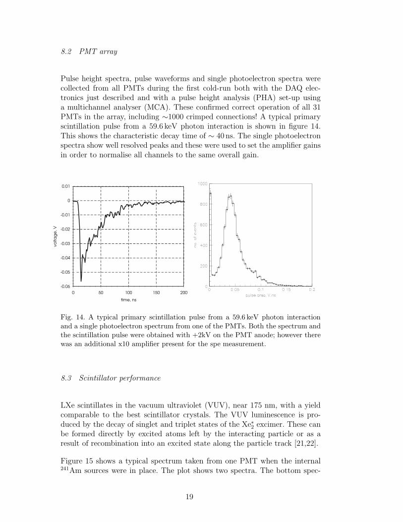
Pulse height spectra, pulse waveforms and single photoelectron spectra werecollected from all PMTs during the first cold-run both with the DAQ elec-tronics just described and with a pulse height analysis (PHA) set-up usinga multichannel analyser (MCA). These confirmed correct operation of all 31PMTs in the array, including ∼1000 crimped connections! A typical primaryscintillation pulse from a 59.6 keV photon interaction is shown in figure 14.This shows the characteristic decay time of ∼ 40 ns. The single photoelectronspectra show well resolved peaks and these were used to set the amplifier gainsin order to normalise all channels to the same overall gain.
-0.06
-0.05
-0.04
-0.03
-0.02
-0.01
0
0.01
0 50 100 150 200
time, ns
vo
lta
ge
, V
Fig. 14. A typical primary scintillation pulse from a 59.6 keV photon interactionand a single photoelectron spectrum from one of the PMTs. Both the spectrum andthe scintillation pulse were obtained with +2kV on the PMT anode; however therewas an additional x10 amplifier present for the spe measurement.
8.3 Scintillator performance
LXe scintillates in the vacuum ultraviolet (VUV), near 175 nm, with a yieldcomparable to the best scintillator crystals. The VUV luminescence is pro-duced by the decay of singlet and triplet states of the Xe∗2 excimer. These canbe formed directly by excited atoms left by the interacting particle or as aresult of recombination into an excited state along the particle track [21,22].
Figure 15 shows a typical spectrum taken from one PMT when the internal241Am sources were in place. The plot shows two spectra. The bottom spec-
19

trum was taken with the whole arrangement covered with liquid xenon. Thetwo spectral features are the 59.6 keV line from 241Am and a blend of the26.3 keV 241Am γ-ray with a 30 keV line resulting from escape of Xe K-shellfluorescence photons. Using the measured single photoelectron spectrum fromthis PMT gives a signal level of ∼12 phe/keV. For this measurement there isno applied electric field. The top spectrum was taken with the liquid level be-tween the source and the PMT window. The interaction occured in the liquidphase and the improved light collection (up to ∼ 17 phe/keV is a result oftotal internal reflection at the liquid gas interface due to the refractive indexmismatch. The resolution from the two-phase spectrum is ∼ 13% FWHM.More detailed and extensive physics results from the first cold run will bepublished separately[23].
Fig. 15. Pulse height spectra obtained from the 241Am primary scintillation signalsduring the first cool-down test. The two panels correspond to two different liquidxenon levels. The highest energy peaks in both spectra are at 59.6 keV.
8.4 Two-phase operation
Once the radioactive sources used for the measurements in the previous sec-tion had been removed the second and subsequent cold-runs have successfullyloaded the detector with liquid xenon. A capacitive level-sensing system probesthe liquid xenon height with sub-mm accuracy at three locations in the cham-ber. A signal from one of these coaxial capacitor structures, readout to 0.03 pF
20

accuracy, is shown in figure 13. In underground operation, these sensors will beintegrated with an active levelling system in order to maintain the electrodesparallel to the liquid surface, guarding the heavily shielded detector againstany structural deformation of the underground cavern.
With the xenon filled to its nominal depth, but with no applied electric field,figure 16 shows 57Co spectra obtained with an external uncollimated sourceplaced above the detector. Two spectra are shown, both reconstructed usingthe outputs from all the PMTs. The shaded one, however, only includes eventsin which the peak signal occurred in one of the inner seven PMTs. This ‘colli-mated’ spectrum has a FWHM of ∼ 25%, which we expect will improve oncefinal corrections for PMT sensitivities are done. The broad shoulder on the lowside for the uncollimated spectrum is purely due to light collection variationtowards the edge of the xenon volume (way outside the fiducial volume).
Fig. 16. Pulse height spectra obtained from using an external 57Co source above theinstrument.
After the zero-field tests, 13.5 kV were applied between the cathode grid andthe anode mirror, setting up a field of 3.0 kV/cm in the liquid. Figure 17 showsa typical signal from a γ−ray interaction in the liquid. The fast scintillation isthe primary signal, S1, caused by direct excitation created by the photoelec-tron. The second, broader signal, S2, occurs when the ionisation also createdhas drifted to the liquid surface and has been extracted into the gas phase.Once in the gas phase the electric field is strong enough to cause excitationleading to a burst of additional photons. The time delay depends on the depth
21

at which the interaction happened and the drift velocity at our operating fieldsis ∼2.5mm/µs. The width of the secondary depends on the gas gap and theelectric-field in the gas. The secondary emission shows a flat plateau as thecharges drift across the gap. The rise and fall time is due to a combinationof extraction dynamics, diffusion and the gas scintillation time-constant. Theratio of the two areas (S2/S1) is ∼150 as expected at this field.
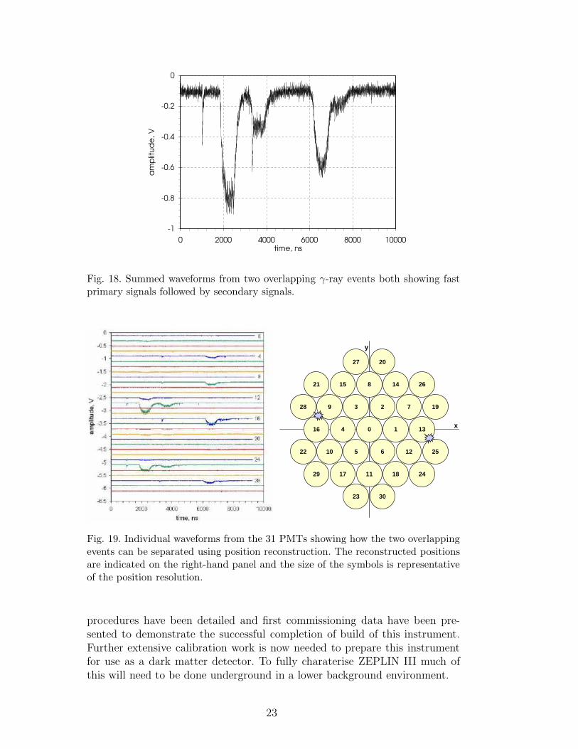
One of the key design drivers of ZEPLIN-III was the ability to resolve eachinteraction point in the three dimensions. A position reconstruction algorithmwas developed from simulated datasets which will provide sub-cm resolutionin the horizontal plane [24]. Even before this is applied to real data, thisspatial sensitivity is well demonstrated in figures 18 and 19, showing an eventin which two interactions have overlapped in time. Moreover there are at leastfour secondary signals. Without position sensitivity it would not be possibleto separate these two events just from the summed signals. However, lookingat the individual PMT traces (left-hand panel in figure 19) it is immediatelyobvious that these two events have happened in very different parts of thedetector (right-hand panel) and they can be unambiguously separated. Theyare both double-Compton scatters.
-1.8
-1.6
-1.4
-1.2
-1
-0.8
-0.6
-0.4
-0.2
0
0.2
0 1000 2000 3000 4000 5000 6000time, ns
am
plit
ud
e,
V
Fig. 17. Summed waveforms from a γ-ray event showing a fast primary pulse followedby the secondary wider pulse from electroluminescence in the gas phase caused byionisation drifted from the event site. The two traces shown are from the dual rangeDAQ. The low-sensitivity data have been multiplied by 10.
9 Summary
The key design features of the ZEPLIN III instrument have been described.The challenging and pioneering aspects of the manufacturing technologies and
22
-1
-0.8
-0.6
-0.4
-0.2
0
0 2000 4000 6000 8000 10000time, ns
am
plit
ud
e,
V
Fig. 18. Summed waveforms from two overlapping γ-ray events both showing fastprimary signals followed by secondary signals.
0 1
23
4
5 6
7
8
9
10
11
12
13
1415
16
17 18
26
19
20
21
22
23
24
25
27
28
29
30
x
y
Fig. 19. Individual waveforms from the 31 PMTs showing how the two overlappingevents can be separated using position reconstruction. The reconstructed positionsare indicated on the right-hand panel and the size of the symbols is representativeof the position resolution.
procedures have been detailed and first commissioning data have been pre-sented to demonstrate the successful completion of build of this instrument.Further extensive calibration work is now needed to prepare this instrumentfor use as a dark matter detector. To fully charaterise ZEPLIN III much ofthis will need to be done underground in a lower background environment.
23

10 Acknowledgements
This work has been funded by the UK Particle Physics And Astronomy Re-search Council (PPARC). We would like to acknowledge the superb coppermachining achieved within the Imperial College Phyiscs Department work-shop led by R. Swain, and the development of new welding techniques by TheWelding Institute.
References
[1] T. J. Sumner (2005), New Astronomy Reviews 49, 277–281.
[2] H. M. Araujo (2005), Proc. Int. Conf. Dielectric Liquids, Coimbra, Portugal,IEEE Press (IEEE Cat. 05CH37643), 305.
[3] G. J. Alner et al. (2005), New Astronomy Reviews 49, 259–263.
[4] G. J. Alner et al. (2005), Nucl. Instrum. Meth. A555, 173–183.
[5] B. A. Dolgoshein, V. N. Lebedenko & B. U. Rodionov (1970), JETP Lett. 11,513
[6] T. J. Sumner et al. (1999), Proc. 26th Int. Cosmic Ray Conf., 2, ed. D. Kieda,M. Salamon & B. Dingus, 516.
[7] A. S. Howard et al. (2001), Proc. 3rd Int. Workshop on the Identification of Dark
Matter, ed. N. J. C. Spooner & V. Kudryavtsev, Singapore: World Scientific,457.
[8] D. Yu Akimov et al. (2003), Proc. 4th Int. Workshop on the Identification
of Dark Matter, ed. N. J. C. Spooner & V. Kudryavtsev, Singapore: WorldScientific, 371.
[9] D. Davidge (2003), PhD Thesis, University of London.
[10] J. Dawson (2003), PhD Thesis, University of London.
[11] H. M. Araujo et al. (2006), Astropart. Phys. accepted. (arXiv:astro-ph/0603243)
[12] E. Aprile et al. (2006), (ArXiv: astro-ph/0601552)
[13] H. M. Araujo et al. (2004), Nucl. Instrum. Meth. A521, 407–415.
[14] N. J. T. Smith et al., in preparation.
[15] ANSYS Inc. (www.ansys.com)
[16] CRC Handbook of Chemistry & Physics, pp. 12-120
[17] http://www.twi.co.uk/
24

[18] http://www.alconox.com
[19] http://www.saesgetters.com/
[20] R. Walker et al. in preparation
[21] S. Kubota et al. (1979), Phys. Rev. B 20(8), 3486–96.
[22] A. Hitachi et al. (1979), Phys. Rev. B 27(9), 5279–85.
[23] V. Chepel, C. Thorne et al. (2006), in preparation.
[24] A. Lindote et al. (2005), Nucl. Instrum. Meth. A, in press.
25