C Animationand Basic Perspective, H Scene Design, A P T
17
Perspective, Scene Design, and Basic Animation Part of designing video games today involves creating amazing images and realistic game worlds. To create these features, a designer must decide how to present the view to the player and how to make everything move in a realistic fashion. In this chapter, you will become familiar with the differences between first person, second person, and third person perspectives. You will also see how char- acter and scene designs are completed in both two- dimensional and three-dimensional game worlds. Lastly, you will explore how the player moves in the game world and how realistic movements are created with characters and background objects. C R E T P A H 4 Chapter 4 Perspective, Scene Design, and Basic Animation 3 Objectives After completing this chapter, you will be able to: game perspectives. the elements of a scene. elements used to convey mood and theme. issues of clarity for scaled computer-generated images. how to construct 3D models. static and active animation. terminology used in artistic creations and computer-generated images. artistic assets for a video game. how pixel and vertex shading are used to create the illusion of depth. Perspective The gameplay is how the game is presented to the player. The perspec- tive of a video game is the view that the player has during gameplay. There are three different modes of perspective: first person, second person, and third person. The perspective describes how the gameplay is displayed on the screen and the position of the player within the game. First-Person Perspective First-person perspective is a view of gameplay where the player sees the game through the eyes of the character, Figure 4-1. First person is often used for driving and shooting games. For a game to be in first person, the player would not be able to see the character being controlled, but can see everything the character sees. This is the closest a player comes to “being the character.” Imagine a racecar game where the view of the gameplay is that of looking through the windshield. You can see all of the turns and cars in front Explain Describe Identify Explain Describe Contrast Define Create Summarize This sample chapter is for review purposes only. Copyright © The Goodheart-Willcox Co., Inc. All rights reserved.
Transcript of C Animationand Basic Perspective, H Scene Design, A P T

Perspective, Scene Design, and Basic AnimationPart of designing video games today involves creating amazing images and
realistic game worlds. To create these features, a designer must decide how to
present the view to the player and how to make everything move
in a realistic fashion. In this chapter, you will become familiar
with the differences between first person, second person,
and third person perspectives. You will also see how char-
acter and scene designs are completed in both two-
dimensional and three-dimensional game worlds.
Lastly, you will explore how the player moves in the
game world and how realistic movements are created
with characters and background objects.
C RETPAH 4
Chapter 4 Perspective, Scene Design, and Basic Animation 3
ObjectivesAfter completing this chapter, you will be able to:
gameperspectives.
the elementsof a scene.
elements used to conveymood and theme.
issues of clarity for scaledcomputer-generated images.
how to construct 3D models.
static and active animation.
terminology used in artistic creations and computer-generated images.
artistic assets for a video game.
how pixel and vertex shading are used to create the illusion of depth.
PerspectiveThe gameplay is how the game is presented to the player. The perspec-
tive of a video game is the view that the player has during gameplay. There are three different modes of perspective: first person, second person, and third person. The perspective describes how the gameplay is displayed on the screen and the position of the player within the game.
First-Person PerspectiveFirst-person perspective is a view of gameplay where the player sees
the game through the eyes of the character, Figure 4-1. First person is often used for driving and shooting games. For a game to be in first person, the player would not be able to see the character being controlled, but can see everything the character sees. This is the closest a player comes to “being the character.”
Imagine a racecar game where the view of the gameplay is that of looking through the windshield. You can see all of the turns and cars in front
Explain
Describe
Identify
Explain
Describe
Contrast
Define
Create
Summarize
This sample chapter is for review purposes only. Copyright © The Goodheart-Willcox Co., Inc. All rights reserved.

4 Video Game Design Foundations
of you, maybe even some in the rear view mirror. You can also see the dash displays and even “your” hands on the steering wheel. It looks just like you are sitting in the driver’s seat. This view is from the first-person perspective of the driver. It is as if your character has a head-mounted camera and you only see exactly what your character sees.
A substantial amount of programming is required to create first-person games. The reason for this is that the player view remains nearly centered in the screen. All movements of the character require the entire scene to move. Instead of seeing your character take a step forward from an overhead view, in first-person perspective the entire background scene moves one step closer to the camera.
Second-Person Perspective
Second-person perspective is extremely rare in video games. In second-person perspective, the player sees the game as if the player were the
Target
Lives Weapon
Remainingammunition
Figure 4-1. This game, called Cowboy Billy Boom, shows action in first-person perspective. Notice how the view is seen as if the camera were on the head of the player. (www.freeonlinegames.com)
CHEAT CODE: CAMERACamera refers to the viewpoint of the game. The camera records the action of the
game and displays it on your screen. The camera should follow the player wherever the character goes.
THINK ABOUT ITACTIVITY 4.1Second-person perspective is the
least-used view in video game design. Other than an example of baseball, when do you think
it is appropriate to use second-person perspective?
Chapter 4 Perspective, Scene Design, and Basic Animation 5
opponent or an intermediary, Figure 4-2. Some sports games use second-person perspective. Imagine a baseball game where your character is at bat and the view, or perspective, is from the pitcher throwing the ball. See Figure 4-3.The pitcher is the second person involved in the action, making this a second-person perspec-tive. This perspective does not work very well in shooter and combat games. The player would be given a view of their character from the point of view of the person the player is attacking.
Third-Person Perspective
Often called a spectator view, third-person perspective is the most versatile view in video game design. In third-person perspective, the play is viewed by a person who is not the player’s character or the player’s opponent, but rather a neutral third person. This view shows both the player and the opponent. This perspective also allows for multiple viewing angles. The player could be viewed from overhead, behind, or any angle left, right, or forward of the player. Most two-dimensional
Action takes placeon this screen, whichthe player cannot see
Action is seenfrom this person’s
perspective
Directions to player
Figure 4-2. This is a unique concept for a second-person shooter game from kongregate.com. The person in the chair tells you where you are and what you are doing. You have to shoot the monster without seeing the screen. Here is an implementation of second-person dialog (speaks directly to you) in gaming. (www.kongregate.com)
Opponent character
Playercharacter
Figure 4-3. Happy Land Homerun Derby is a second-person perspective game. You see your character from the view of the pitcher. This game can be played from the perspective of either the pitcher (first person) or the batter (second person).

6 Video Game Design Foundations
Obstacles
Obstacles(platforms)
Player character
Player character
Prizes
Platforms
A
B
Figure 4-4. A—This game, called Adventure Elf, uses a classic platform view. Your elf avatar must collect the cookies, navigate the platforms, and capture the penguins. B—This game also uses a classic platform view. In this game, called Dirt Bike, you must navigate the motorcycle avatar across the obstacles. (www.kewlbox.com; www.freeonlinegames.com)
Chapter 4 Perspective, Scene Design, and Basic Animation 7
games use either the overhead or platform view. Platform view shows the char-acter in profile and a side view of all obstacles, Figure 4-4. Overhead viewshows the character and surroundings from a perspective high overhead, Figure 4-5.
Changeable PerspectiveSome games allow the player to set the camera perspective. Many
driving games allow the player to switch from first person (behind the steering wheel) to third person (overhead view that shows your car and the cars near you, Figure 4-6.
A first-person shooter game may show action from a third-person perspective when moving through the battlefield. When the player gets to the correct location, the perspective changes to first person. The player then looks down the sight of the weapon.
ScenesA scene is the placement of objects on a game frame to create an
attractive layout, obstacles, and objectives that convey the story and mood.
Goals
Obstacles Playercharacter
Safe locations
Figure 4-5. This Frogger game from FreeOnlineGames.com uses a classic overhead view. The view shows a 2D perspective looking straight down on the character and game environment. (www.freeonlinegames.com)

8 Video Game Design Foundations
An essential part of designing a video game is creating the background images to enhance the gameplay experience. The background can be composed of many different objects to create the environment—the feel and mood of a scene, Figure 4-7. The choice of trees, buildings, sky, clouds,
lighting, and general color palette are put in place as boundaries and simple scenery for the gameplay.
Some background objects can have active characteristics. Other background objects are simply there to act as scenery or to set the mood of the scene. An active object is one with which the player can interact. A back-ground object is one with which the player cannot interact. Most scenery is a background object. However, some scenery, such as plat-forms, are active objects because they must provide some interaction. In the case of a plat-form, the player must be able to walk on it, Figure 4-8. Most active scenery objects restrict
the player’s movement or damage or reward the player. In a game, a back-drop may include buildings, trees, and other objects that do not damage or reward the player. These active objects act as an obstacle for the player to avoid. A backdrop object differs from a background object because it is an element of the scenery that the player can touch or walk behind.
Think of a background object like the sky. It adds artistic design to the scene, but does not move or interact with the player. This like when you get your picture taken. The photographer pulls down a background screen of
Allows achange in
perspective
Figure 4-6. This arcade racing game allows the player to change perspective by pressing the View button. On the right-hand side of the steering wheel is a button that allows the player to look behind their car when the current view is a first-person perspective.
CHEAT CODE: COLOR PALETTEA color palette is the set of colors used consistently throughout a scene to maintain
mood. Generally, the desired mood sets the color palette that will be dominated by one of four general colors to
maintain the mood: red, yellow, blue, or gray. In general, red is used for passion, yellow for
cheerful, blue for peaceful, and gray for gloomy. The rest of the color palette is selected using contrasting and complementary colors from the color wheel.
Chapter 4 Perspective, Scene Design, and Basic Animation 9
a beach at sunset. It is just there to make the scene look better. You are not actually at the beach, it just looks that way.
The photographer might also use some backdrop objects to help it look like you are at the beach. Here, the photographer places some stairs on one side of the scene leading to an imaginary dock. The stairs are part of the scenery, but you can walk on them. Therefore, they are considered a backdrop object. The combination of the background object (sky) and the backdrop object (stairs) really helps sell the idea that you are at the beach.
In video game design, a designer must set a mood for a scene to help add emotion and anticipation to the gameplay, Figure 4-9. The choice of an object, its color, and shape help set the mood of the frame. The choice of a back-drop color could determine if it is a blue sky, a sunny day, or a dark night.
If the designer is setting a scary scene, the use of dark colors, a gray or muted palette, and sharp-edged shapes will help set the mood. As
Figure 4-7. Notice how this scene has dark colors for the sky and ground. It even has a dark, scary tree and a ghost character. Yet, the building is a gingerbread house, there is a holiday tree out front, and an elf character is carrying presents. These items are created with bright, cheery colors. This is a mismatched scene. The dark, scary parts do not go with the bright cheery parts.
Backgroundobject (sky)
Characteravatar
Platform
Active objects(rolling balls)
Figure 4-8. In this platform game, the player must avoid the rolling balls. Once the player reaches the top platform, a new game level is launched.

10 Video Game Design Foundations
A B
Figure 4-9. Here, color is used to portray two different moods. A lighthearted mood is portrayed in the game on the left, while a darker and more sinister mood is portrayed in the game on the right. Bright colors convey a happy mood, while the dark colors convey tension.
CASE STUDY:COMPOSING A SCENE
A game scene starts with a background object, like a blue sky with a few white puffy clouds painted in. The background object prevents the character from passing through it. It is always behind all other objects in the scene.
You then add backdrop objects like a road, trees, bushes, light poles, and buildings. Backdrop objects, like the tree, will not let the character pass through it. The character might be able to walk in front of or behind a tree, but should not be able to walk through a tree. The tree also does not move on its own. As a backdrop, the tree will move with the scene, but it does not approach the player, harm the player, or add points for the player.
The sky is a background object. It is always behind all other objects.
(Continued)
These are backdrop objects. The character may pass in front or behind these objects, but may not pass through them.
Chapter 4 Perspective, Scene Design, and Basic Animation 11
players enter this scene, they would anticipate seeing characters and traps related to this type of setting. Opponents would be dimly colored and might be ghosts and skeletons. Anything brightly colored, like a shiny coin, would likely be a reward. In general, dark colors identify opponents and bright colors identify rewards or friends.
StoryboardsBefore you design a scene you must first create a storyboard to sketch
out the design. A sketch of the important frames each with the general ideas for motion, traps, and rewards is called a storyboard, Figure 4-10. Story-boards have been used for years in the motion picture industry. They help organize and plan what will happen in a video game or movie. Your story-board does not need to present great detail, but it should serve as a guide to the digital design of the scene. The storyboard will also help the scene designer to set the dimensions of the frame.
If a tree is supposed to fall and become an obstacle, it must be programmed as an active object instead of a backdrop object. Active objects can be the player, obstacles, objectives, tokens, or anything programmed to move or interact with the player.
The background, backdrop, and active objects are assembled to create a game scene. With these objects in place, the character can be programmed to collect the healthy food items to build strength points and subtract points for eating junk food like the cupcake.
These are the active objects for the game.
(Continued)
The background object, backdrop objects, and active objects are assembled to create the scene.

12 Video Game Design Foundations
Image PropertiesThe scene dimensions are measured in pixels. Pixels, or picture
elements, are the smallest point or dot of color a computer screen can generate. A pixel can only be one color at any given time. All objects displayed onscreen are created with pixels. The computer uses these points to create an image.
While pixels are only used in reference to video displays, this same concept has many applications. Think of drawing a picture by only tapping the point of a pencil on the paper. Each dot represents one pixel used by a
Frame/Time
Date _____ Sheet _____ of ___
Project _______ Artist _______
Frame/Time
Figure 4-10. A storyboard is used to plan an animation or video game. The key frames or events are shown on the storyboard. Then, once the plan is set, the work needed to complete the game can begin.
Chapter 4 Perspective, Scene Design, and Basic Animation 13
video display to show the line. You might have to tap 50 dots to make a line one inch long. The resolution of this line is said to be 50 dots per inch (dpi). The higher the dpi, the higher the resolution.
A fax machine prints at 300 dpi. A standard laser printer prints at 600 dpi. A photographic or fine-quality printer might print as high as 1200 dpi or higher. The clarity of an image is direction-ally proportional to the dpi. The smaller the pixel point, the more dots per inch can be generated and the clearer the picture. However, the image being printed must have a corresponding dpi.
You cannot simply take a low-resolution image and make it bigger. If you do, the image will become blurry, or pixilated, Figure 4-11.
The reason pixilation occurs is the process of interpolation that the computer performs. By breaking apart the word interpolation, you can construct the correct meaning: inter is the space between and polation is a polishing
Low-resolution image High-resolution image
Figure 4-11. An image that is low resolution cannot simply be increased in size. As size goes up, resolution goes down. This can cause an image to become blurry.
CHEAT CODE: CLARITYWhen designing digital images, clarity
refers to how clearly images are defined with either line or pixel density. Blurry, faded, too light, too dark, or pixilated
images are not clear or have poor clarity.

14 Video Game Design Foundations
or finishing. Therefore, the definition of interpolation is a refining of the spaces between the points or pixels of an object.
When a computer makes an object larger, it needs to fill in the spaces between each pixel. This effect is called dithering. If it does not fill in that space, the object would look really funny as it would separate into little dots. The computer uses interpolation to dither an image when it is resized.
When dithering an image, the computer chooses a blended color to fill in between the pixels that moved. This process repeats every time the object is enlarged by more than one pixel spacing. As more blended pixels are inserted, the object develops a blurry look as the color between the two native poles or pixels continues to distort.
In Figure 4-12, green pixels touch red pixels in certain locations. If this picture is
enlarged, the computer must interpolate a new pixel between these two native pixels. The figure shows what an interpolated pixel might look like. The computer adds a pixel and colors it based on information from the surrounding pixels. The red-green-blue (RGB) color of the red pixel is 222,0,0 (222 density of red, 0 green, and 0 blue). The RGB color of the green pixel is 0,128,0 (0 density of red, 128 green, and 0 blue). The inter-polated pixel has an RGB color of 222,128,0. As you can see, that color is nothing like either of the original colors. This causes the picture to get fuzzy, distorted, and discolored as the size increases.
Designers of digital scenes need to make the images clear enough to look like the item being shown. However, making images too fine will take more computer memory to generate items due to the greater number of pixels. The designer will also have to know on what type of computer system the game will be played. That determines the total background frame size
CHEAT CODE: NATIVE POLESNative poles or native pixels are the original pixels of an object before it was modified.
The computer creates an interpolated pixel between two native pixels when an object is resized.
Adjacent pixels
Interpolated pixel
Figure 4-12. When an image is resized, the computer must decide what color the new pixels should be. This can cause an image to become blurry or muddy.
Chapter 4 Perspective, Scene Design, and Basic Animation 15
in pixels. For example, if the computer monitor setting is set to 1280 780 resolution, a designer must create a frame that is 1280 pixels wide and 780 pixels high to fill the screen. If a game frame is set larger than the screen size, some images may not show. If that happens, a designer might need to modify the screen settings to fit or allow the game frame to scroll. If the frame scrolls, it moves with respect to the character, Figure 4-13.
Visible screen
Figure 4-13. This is how a scrolling map is shown on screen. All sections of the map are active and will continue to have active objects in motion even when not displayed. As the player moves, the camera centers the player on the map. Large maps with continuing action off screen take a lot of computing power to keep the game running smoothly.
CASE STUDY:DIGITAL COLOR MODELS
To create the millions of colors we see in real life, computers need to mix basic colors. In Chapter 1, you saw how the color wheel allows you to mix the three primary colors (red, blue, and yellow) to create the complementary and contrasting colors. Digital color models are similar, but slightly different. Two common digital color models are RGB and HLS.
The RGB, or red, green, blue, model combines three colors in different densities to create different colors. The RGB color model is used on most personal computers, television sets, LCDs, and handheld devices. These display screens can easily blend the three color components to create white, black, and millions of colors in between. The bit depth of the color (8 bit, 16 bit, 32 bit, etc.) determines the number of colors that can be created.
In the RGB model, a color value of 0,0,0 (red = 0, green = 0, blue = 0) is black, as shown in the figure. This makes black the base color for the RGB model. So starting with black,
when you add red, blue, or green in different densities (values), new colors are created. If you add a maximum amount of red, green, and blue (255,255,255), the color is white. The maximum amount of color that can be added is 255. Every digital color can be written in RGB format.
(Continued)
Target
RGBvalues
Color isblack
This is the Colors dialog box from a Microsoft Office application. In this example, the RGB color model is used to define black.

16 Video Game Design Foundations
After determining the screen dimensions, the designer needs to determine the gameplay dimensions. The gameplay can be designed as 2D, 2.5D, or 3D.
Two-Dimensional Games
Two-dimensional (2D) games have characters and backgrounds that play in only two dimensions: length and width, Figure 4-14.A character in a 2D game can only move up, down, left, or right to the limit of the length and width of the game frame. This style of game has flat characters on a flat background.
There are two terms commonly used to describe the presentation of a 2D game on the screen: game frame and visible play area. A game frameincludes all of the items programmed for a complete scene or level of a game. The game frame is the entire game world for that scene. This includes items visible on screen and all items that exist off screen. The part of a game frame that is displayed on the video screen is called the visible play area.
The HSL model uses hue, saturation, and luminescence values to create colors. The hue value determines which color in the spectrum shown is the basis, from red to purple. The saturation level is the amount of hue. In other words, it is the density of the color. The higher the saturation, the more of the base color used.
Together the hue and saturation work like the X and Y coordinates of a number line. Notice in the figure the target site that is created on the palette by entering a value for the hue and saturation below. This technique chooses a color from the palette.
The luminescence setting is how bright or dark the color appears. The average color brightness is 112. If luminescence is set to 0, the color has no luminescence and is black. If luminescence is set to 255, the color is white. Values in between result in varying degrees of the darkness/lightness of the base color.
(Continued)
Target
HSLvalues
Color isorange
In this example, the HSL color model is used to define orange.
THINK ABOUT ITACTIVITY 4.2A computer adds pixels through
interpolation when enlarging an object. What processes do you think occur when the computer
reduces an object?
Chapter 4 Perspective, Scene Design, and Basic Animation 17
In addition to tracking off screen objects, the computer may also have to scroll the game frame as the player moves. Scrolling is where the game frame is moved so the position of the player is always in the visible play area. It is important to remember that all objects on the game frame remain, even though they are not visible.
Scrolling can easily be demonstrated using your hand and a textbook. The textbook is the game frame and your hand is the visible play area. Lay your hand on the textbook and move the book without moving your hand. That is how the computer scrolls the larger game frame to present a moving view in the visible play area.
A 2D character can be made into multiple poses to create a sprite character set to display the movement animations used in the game. Recall from Chapter 1 that a sprite is a 2D asset. A sprite character set, then, is a collection of 2D assets, such as different poses, for a single character. A sample sprite character set from RPG Maker XP is shown in Figure 4-15.RPG Maker XP is a game engine for developers creating role-playing games.
Length
Width
Figure 4-14. Flat shapes like those shown above are 2D objects. The have length (X) and width (Y) dimensions only.
NN
S
E
W
Figure 4-15. This goblin avatar has 16 poses to animate walking in four directions (North, South, East, and West). Sprites traveling in more than four directions need more poses. If the goblin sprite needs to move northeast, a new animation set for that direction must be created and programmed into the game.

18 Video Game Design Foundations
Direction of travel for sprites is typically defined by compass directions: North, South, East, and West. Some sprite character sets can have 16 direc-tions of motion just for walking on a flat surface, as shown in Figure 4-15.
Everything in a game frame is located with a coordinate system. The coordinate system is very similar to the coordinate graphing you have done in your math and science classes. It involves the X coordinates (left and right, horizontal directions), Y coordinates (up and down, vertical directions) and Z coordinates (depth or closer and farther directions). In 2D games the Z value is always 0.
If you remember Cartesian coordinates from your math class, moving to the right of the origin, the value of X changes in the positive direction. When you move up from the origin, the value of Y changes in the positive direction. The coordinates of the origin are written as (0,0,0). This means X, Y, and Z all have a value of zero. The X value is always first, followed by the Y value and then the Z value. Since the Z value is always zero in 2D games, it can be removed from the coordinate set. Then, the origin is written (0,0), Figure 4-16.
If you move to a different point other than the origin, you need to iden-tify where on the X and Y axis that point exists. If you locate the colored dot on the graph in Figure 4-16, the coordinates are (5,3) or X = 5 and Y = 3. The same concept of coordinates applies to game design, except the Y axis is flipped in some game engines.
Figure 4-17 shows an image from The Games Factory 2. This shows a 2D frame where the origin of the coordinate system (0,0) for the frame
start is the top-left corner. If the pointer moves one pixel to the right along the X axis, the coor-dinates are 1,0. If the pointer then moves one pixel down along the Y axis, the coordinates are 1,1. To find the total screen size, the pointer can be moved to the bottom-right corner. Here, the coordinate indicator would read 640,800 as this screen size is 640 pixels wide and 800 pixels tall.
Also included in the concept of 2D depth perception is parallax movement. To create depth when a 2D character moves, designers create a background from multiple background maps. By layering these maps so closer objects are in front of distant objects, the feeling of depth is created. The designer then programs these layered background maps to move at different rates to simulate the movement you see in nature. The map closest to the character moves fastest. The map farthest from the char-acter moves slowest. Next time you play the classic game Mario Brothers, look at how the backgrounds move behind the action. You will build a game with parallax later in this course.
+X
+Y
–X
–Y
(0,0)
(5,3)
Figure 4-16. This is the coordinate system used for 2D games. The Z value is always zero. Some game engines flip the negative and positive directions for the Y axis (negative on top, positive on bottom).
CHEAT CODE: PARALLAXParallax describes how objects in the distance seem to move more than objects in the
foreground. This creates a slight change of perspective when the foreground object moves. An easy way to practice this is to
hold one finger up as you point at an object in the distance. Close one eye at a time and the object in
the distance seems to jump to the other side of your finger.
Chapter 4 Perspective, Scene Design, and Basic Animation 19
Two and One-Half–Dimensional Games
Two and one-half–dimensional (2.5D) games have two-dimen-sional background graphics, but uses three-dimensional (3D) characters and obstacles, Figure 4-18. This type of game is a hybrid. The graphics are
designed with three dimensions (length, width, and depth), but the gameplay is still defined by only length and width. This style of game has 3D characters and objects on a flat background. In a true 3D game, objects are programmed to resize, re-shade, and shift view in relation to the camera. In a 2.5D game, however, multiple poses are used. These poses change similar to a 2D character, but each sprite has a 3D appearance.
To create a sprite character set for 2.5D game, the characters and obstacles are all generated with length, width, and depth. Multiple camera angles can be used with a 3D character to produce
Y axis
+
X axis
Coordinateindicator
Top-left corneris 0,0
+
Figure 4-17. This is a 2D frame where the origin of the frame’s coordinate system (0,0) is the top-left corner of the frame.
CHEAT CODE: HYBRIDA hybrid is created by combining features
from two different items. A hybrid car is a combination of an electric car and a car with an internal combustion engine.
A 2.5D game is a hybrid because it combines 2D gameplay with 3D objects.

20 Video Game Design Foundations
a character that works. The character will need to be designed so it can be seen from all of these different angles. Most game designers create these simulated 3D characters with a minimum of 26 viewing angles for each pose. Highly defined characters may have more than 100 viewing angles for each pose.
In some 2.5D games, the character set is replaced with actual 3D models with full articulation. Full articulation means all of a character’s body parts can move through a range of motion in a realistic manner. In these games, the background is still flat and two dimensional, but the charac-ters and interactive objects are true 3D models.
Three-Dimensional GamesThree-dimensional (3D) games have 3D characters and 3D
background objects called models. Recall from Chapter 1 that models are different from sprites. Sprites are defined in two dimensions (X and Y). Models are defined in three dimensions (X, Y, and Z), Figure 4-19. They are computer generated in real time to show the correct angle and pose. It takes a lot of computer processing to make a 3D model move.
The discussions in the following sections are actually oversimplified explanations of how perspective, pixel shading, vertices, scaling, and depth work within a game. However, these discussions should give you a good idea of these concepts that are used to make a 3D scene in a game.
3D obstacle
3D avatar
Gameplay isin a 2D frameeven thoughthe graphicsappear 3D
Figure 4-18. This is a 2.5D game. The game frame is two dimensional, but the characters and obstacles are three dimensional.
Chapter 4 Perspective, Scene Design, and Basic Animation 21
PerspectiveBackground models on the 3D game map
are complex as the computer must generate a game frame that moves in three dimen-sions. It is really not moving in three dimen-sions, but rather the computer displays a view that appears to move in three dimensions. It does this by using visual perspective. Visual perspective creates the sense of depth using shading and narrowing to represent the third dimension of depth on a two-dimensional screen. Important to visual perspective is the concept of a vanishing point.
A vanishing point is the point in the back-ground where edges of all assets will meet at a single point if extended. A rectangular surface will appear pinched into more of a triangular shape. In other words, parallel lines do not appear parallel. Notice how the road in Figure 4-20A appears
to narrow and darken as it recedes into the background. In the far distance, the road vanishes to a single point. In Figure 4-20B, you can better see the vanishing point. By blocking out the background images, you can see the road appears to form a triangle. The farthest point in the distance—the vanishing point—is the top of the triangle. Of course, the edges of the actual road remain parallel, they just appear to meet in the distance.
If you look more closely at the picture, you will also see that the tree tops and all other “north/south” objects vanish to the same point. In Figure 4-20C,red lines are added to the trees where the trunk meets the branches and to the road edges. You can clearly see all objects recede to the same vanishing point. In this case, the vanishing point is centered in the middle of the view. This scene is now divided into four triangles of visual perception.
Figure 4-19. Models are 3D assets. They have length (X), width (Y), and height (Z) dimensions. (Model courtesy of Autodesk, Inc.)
A B C
Figure 4-20. A—The vanishing point is clearly visible in this photo. It is in the middle of the image. B—If the trees and sky are blacked out, the point where the edges of the road converge is obvious. C—Red lines are added to show the receding lines on the road and trees. The receding lines converge at the vanishing point.

22 Video Game Design Foundations
A 3D game engine will create an object using a vanishing point in the center of the screen if the view is first person. If the view is third person, then the vanishing point will be at the midpoint of where the camera is pointed. To achieve a vanishing point, the 3D engine uses the concept of pixel shading and vertices.
Pixel ShadingPixel shading works on the idea that as
you move farther from the light source, things get darker. The game engine shades the pixels of distant objects darker and closer objects lighter. As you move toward a distant object, it will get brighter until it reaches full color when you are next to the object. In addition to distance shading, an object will have different shades of color on different surfaces to give contrast to the object.
VerticesPixel shading is cool, but something has to make the objects get bigger
and move as though you were seeing them get closer. The 3D engine does this by adjusting the distance between vertices on the model. A vertex is a point on a 3D model where the corners of adjacent faces meet.
For example, a cube object has six faces and eight vertices. See Figure 4-21.The maximum number of vertices visible on a cube in a given shaded view is
CHEAT CODE: VERTICESWhile some consider the plural of vertex to be vertexes, it is actually vertices (ver-ti-
sees). A group of more than one vertex is a group of vertices.
THINK ABOUT ITACTIVITY 4.3Think about the phrase, the light
at the end of the tunnel. Think about how you might draw this concept in a very long
straight tunnel. How does the use of a vanishing point work in this drawing?
A B C
Figure 4-21. A—A cube has eight vertices, represented by the spheres. In this view, only seven vertices are visible. B—As the view of the cube is rotated, different vertices are visible and hidden. Now, only six vertices are visible. C—When the view is rotated to show the front face, the cube looks like a square and only four vertices are visible.
Chapter 4 Perspective, Scene Design, and Basic Animation 23
seven. This means from one to four vertices are hidden from view, depending on where the camera is located. Also, notice the pixel shading of the cube shown in the figure, Figure 4-22.To give depth, a shading effect must be added to differentiate between the flat surfaces on the cube. These flat surfaces are known as faces.Without this shading effect or contrast, the object would not be seen as a 3D object. Instead, it would appear as an irregular 2D shape. The same cube in a wireframe view shows the hidden edges and vertices, Figure 4-23.
ScalingThe 3D engine has more work to do than
just render the object on the screen. It must also move the object in a realistic manner. Remember how an object in the distance
Edges cannotbe seen
Edge cannotbe seen
A B
CFigure 4-22. A—Without pixel shading, some of the edges are not visible. This may make the object look 2D, not 3D. B—Compare this view to Figure 4-21B. C—In this view, the cube looks like a square, just as in Figure 4-21C, even without pixel shading.
CHEAT CODE: WIREFRAMEWireframe is a view showing objects as if
they are built with wire, not opaque faces. In a wireframe view, 3D objects have visible lines on the edges, but the faces
are invisible. A view with opaque faces is called a shaded view.
CHEAT CODE: RENDERRendering is adding color and shading
to represent an object. In terms of 3D design, the computer renders 3D objects to make them appear solid and
then projects the image onto a 2D surface (the computer screen).
24 Video Game Design Foundations
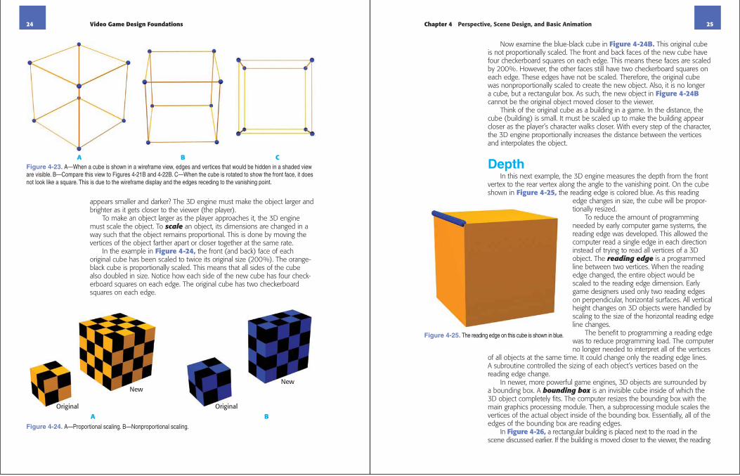
appears smaller and darker? The 3D engine must make the object larger and brighter as it gets closer to the viewer (the player).
To make an object larger as the player approaches it, the 3D engine must scale the object. To scale an object, its dimensions are changed in a way such that the object remains proportional. This is done by moving the vertices of the object farther apart or closer together at the same rate.
In the example in Figure 4-24, the front (and back) face of each original cube has been scaled to twice its original size (200%). The orange-black cube is proportionally scaled. This means that all sides of the cube also doubled in size. Notice how each side of the new cube has four check-erboard squares on each edge. The original cube has two checkerboard squares on each edge.
A B CFigure 4-23. A—When a cube is shown in a wireframe view, edges and vertices that would be hidden in a shaded view are visible. B—Compare this view to Figures 4-21B and 4-22B. C—When the cube is rotated to show the front face, it does not look like a square. This is due to the wireframe display and the edges receding to the vanishing point.
Original
New
Original
New
A BFigure 4-24. A—Proportional scaling. B—Nonproportional scaling.
Chapter 4 Perspective, Scene Design, and Basic Animation 25
Now examine the blue-black cube in Figure 4-24B. This original cube is not proportionally scaled. The front and back faces of the new cube have four checkerboard squares on each edge. This means these faces are scaled by 200%. However, the other faces still have two checkerboard squares on each edge. These edges have not be scaled. Therefore, the original cube was nonproportionally scaled to create the new object. Also, it is no longer a cube, but a rectangular box. As such, the new object in Figure 4-24Bcannot be the original object moved closer to the viewer.
Think of the original cube as a building in a game. In the distance, the cube (building) is small. It must be scaled up to make the building appear closer as the player’s character walks closer. With every step of the character, the 3D engine proportionally increases the distance between the vertices and interpolates the object.
DepthIn this next example, the 3D engine measures the depth from the front
vertex to the rear vertex along the angle to the vanishing point. On the cube shown in Figure 4-25, the reading edge is colored blue. As this reading
edge changes in size, the cube will be propor-tionally resized.
To reduce the amount of programming needed by early computer game systems, the reading edge was developed. This allowed the computer read a single edge in each direction instead of trying to read all vertices of a 3D object. The reading edge is a programmed line between two vertices. When the reading edge changed, the entire object would be scaled to the reading edge dimension. Early game designers used only two reading edges on perpendicular, horizontal surfaces. All vertical height changes on 3D objects were handled by scaling to the size of the horizontal reading edge line changes.
The benefit to programming a reading edge was to reduce programming load. The computer no longer needed to interpret all of the vertices
of all objects at the same time. It could change only the reading edge lines. A subroutine controlled the sizing of each object’s vertices based on the reading edge change.
In newer, more powerful game engines, 3D objects are surrounded by a bounding box. A bounding box is an invisible cube inside of which the 3D object completely fits. The computer resizes the bounding box with the main graphics processing module. Then, a subprocessing module scales the vertices of the actual object inside of the bounding box. Essentially, all of the edges of the bounding box are reading edges.
In Figure 4-26, a rectangular building is placed next to the road in the scene discussed earlier. If the building is moved closer to the viewer, the reading
Figure 4-25. The reading edge on this cube is shown in blue.

26 Video Game Design Foundations
edge is longer. The building must be proportionally increased in size. The 3D engine increases the distance between the vertices to stretch the object.
Additionally, when the player moves around the scene, the vertices on objects must move to show a change of direction. Figure 4-27 shows two cubes. Notice the position of the character and vertices in Figure 4-27A. In Figure 4-27B, the character has moved in the scene. The cube is exactly the same, just viewed from a different angle. Notice the new positions for the vertices.
A BFigure 4-26. A—Two buildings have been added to the scene. The building closest to the viewer appears proportionally larger than the building farthest from the viewer. In reality, the models are the same size. B—Textures have been added to the building models.
A BFigure 4-27. A—The character is viewing the cube from one angle. B—As the character moves, the 3D engine moves the vertices on the cube. The original vertices are shown in blue and the new locations are shown in red. Notice how the lower-right vertex is now visible to the character, but the lower-left vertex is no longer visible.
Chapter 4 Perspective, Scene Design, and Basic Animation 27
Round ObjectsRounded objects like spheres can be a challenge for a 3D engine. A
sphere has no corners. Different engines may use different solutions to this problem. In most cases, the sphere is made up of several flat, rectangular
or triangular faces that make the object look round. Where these faces connect is a vertex. With these vertices, the 3D engine can resize the sphere by changing the distance between the vertices. This is also how facial features and other rounded character assets are resized.
The type of sphere described above is called a UV sphere. The name comes from the process needed to wrap a texture map around the object. A 2D image is stretched around the sphere, Figure 4-28. U is the same as X and V is the same as Y. In some applica-tions, a third element (W) is added for the Z dimension.
An orange is a good example of a UV sphere, Figure 4-29. A UV sphere uses slices like the segments of an orange to make the object round. The more slices (segments), the more rounded the sphere appears. Imagine the segments of the orange as the faces of the UV sphere. The peel of the orange is the texture map stretched over the sphere. The texture map provides the orange color and the wrinkly quality of the peel. Brown spots and irregular flaws added to the texture map will make the image more realistic.
Another type of sphere is a geodesic sphere. Instead of rectangular and triangular faces, a geodesic sphere has faces of regular polygons. This is the way a soccer ball is made, Figure 4-30.There are different types of geodesic spheres. For example, an icosphere is based on a 20-sided object. Its faces are equilateral triangles.
THINK ABOUT ITACTIVITY 4.4A 3D engine changes the
dimensions of a model by changing the distance between vertices. How does this work on
an object like a sphere that has no corners?
Figure 4-28. A—This is a 2D texture map of Earth. B—To create a model of Earth, draw a sphere. C—The texture map is wrapped onto the sphere to finish the model of Earth. (Texture provided by NASA)
THINK ABOUT ITACTIVITY 4.5Think about the example of the
orange and the soccer ball as a UV sphere or a geodesic sphere. Come up with two other
examples each for UV sphere and geodesic sphere.
Figure 4-29. The segments of an orange are fit together to approximate a round shape. Notice how the segments relate to the sphere shown in Figure 4-28B.

28 Video Game Design Foundations
What Is a Mesh?All 3D objects are made from intercon-
nected polygons stuck together to form a shape. These polygons, or polys, stick together along their edges and vertices in what is referred to as a mesh. Creating a mesh is like gluing all of the pieces together to make one object. However, the computer does the “gluing” based on the size you give the object.
The mesh provides the shape for an object, Figure 4-31A. After the mesh is complete, textures, called materials, need to be applied, Figure 4-31B. Often, a single 2D texture map contains more than one image, Figure 4-31C.Once the texture map is wrapped onto an object, the images are aligned to create the finished object, Figure 4-31D.
The poly count is the number of polygons used to make a 3D object. This number is a crit-ical measurement. The more polys, the more life-like the object becomes, Figure 4-32. So, why not make all objects with a high poly count? Simple; every polygon needs to be morphed as the object is moved. The computer needs to calculate the change in distance between each vertex of the polygon as the object gets bigger, smaller, and moves to a different view. If every object has a high poly count, it would take an enormous amount of time for the computer to render the objects as they move. Some proces-sors would not be able to keep up with the calculations. On these systems, the view may
skip, play slowly, or appear to have glitches.Look at the example of the expanding-ball toy. Imagine how long it
would take to calculate the change in distance between every vertex each time the ball changes shape. The computer must do just that. The more polygons, the more vertices and the harder the task.
The color and texture maps assigned to an object tessellate around the object. Each poly has a piece of the texture image on its surface, like a mosaic. See Figure 4-33. The amount of tessellation is controlled by the number of polys on the object. The higher the poly count, the greater the tessellation. Therefore, the higher the poly count, the smaller each slice of the color or texture map.
A
BFigure 4-30. A—Notice the black and white shapes on the surface of the soccer ball. These are regular polygons fit together to simulate a round shape. B—Notice the faces on the geodesic sphere. In this example, they are regular triangles. These are fit together to approximate a round object.
CHEAT CODE: MOSAICA mosaic is a design created by placing colored tiles, stones, or glass in a pattern
to make a picture. This relates to 3D models because the model uses colored polygons to create an image
just like the mosaic picture.
Chapter 4 Perspective, Scene Design, and Basic Animation 29
A B
C D
Figure 4-31. A—This is a mesh for a cartoonish biplane. B—Some of the objects have materials assigned. C—This is the 2D texture map that will be assigned to the remaining parts of the biplane. D—The fully textured biplane. Notice how the 2D texture map has been applied to the mesh. (Model courtesy of Autodesk)
Figure 4-32. As the polygon count increases, the smoothness of round surfaces increases. However, it also takes longer for the computer to render. Here, the sphere on the right looks the most realistic. For a game, however, maybe the middle sphere is used because it still looks like a sphere, but has fewer polygons.
Figure 4-33. Notice how these tiles fit together to make the image. If you think of each tile in the mosaic as a polygon, you can see how a texture would be mapped to the polys on a 3D game object.

30 Video Game Design Foundations
AnimationWhen a character or object moves on the screen, it is said to be
animated. An animation is a series of frames played in sequence with small differences between each frame. The brain interprets these small differences as motion. Think of the flip cartoons you may have sketched on the corners of notebook pages. This is a very basic animation.
Static animation is where the object retains its original pose while moving. An example is a stick figure with arms, legs, and head kept in the original position, but the figure moves across the computer screen, Figure 4-34. Since the arms and legs do not move, the figure appears to slide across the screen. You can try static animation at your desk. Pick up a pencil or pen and hold it in front of you. Move the pencil up and down while holding it in the original posi-tion. Hurray! Static animation in practice.
In active animation, an object changes pose while moving on the screen. An example of this is a stick figure with legs that move in a walking motion to take steps as the figure moves across the screen, Figure 4-35.
A B
C D
Figure 4-34. These are frames from a static animation created in Pivot Stickfigure Animator. Notice that the stick figure moves to a different position without moving arms and legs. The body stays static as it moves.
Chapter 4 Perspective, Scene Design, and Basic Animation 31
A real world example might be flipping your pencil in the air. The top and bottom of the pencil change position as it moves up and down. Hurray! Active animation in practice.
A B
C D
Figure 4-35. These are frames from an active animation created in Pivot Stickfigure Animator. Notice the different arm and leg positions of the stick figure as it walks across the screen. Moving the arms and legs creates an animation set for this figure that can now be classified as walking instead of just moving.

32 Video Game Design Foundations
Chapter 4 Review QuestionsAnswer the following questions on a separate sheet of paper or complete the digital test provided by your instructor.1. What is the view that the player has during gameplay?
2. Which type of game is shown through the player’s eyes?
3. Overhead view and platform view are examples of _____ perspective games.
4. Define scene as it relates to video games.
5. What is the difference between an active object and a static object?
6. Briefly describe the purpose of a storyboard.7. What is a pixel?8. What is the resolution of an image?
9. Define interpolation.10. What characterizes a 2D game?
11. Describe how a 2.5D game is a hybrid of a 2D game and a 3D game.
12. _____ creates the sense of depth using shading and narrowing to represent the third dimension of depth on a two dimensional screen.
13. What is the point called where edges of all assets will meet if extended?
14. How does pixel shading simulate depth?
15. Define vertex.16. If a sphere is proportionally scaled by 200% from an original diameter
of 1 , what is the new diameter?
17. Briefly describe a mesh.18. What is a poly count?19. The greater the _____, the higher the poly count.
20. Define animation.
Chapter 4 Perspective, Scene Design, and Basic Animation 33
Mathematics
MathematicsCross-CurricularSTEM Activities1. The boxes shown below are proportionally sized. Analyze the figure and
determine the correct dimensions for the larger object.A. Large object X dimension _____B. Large object Y dimension _____C. Large object Z dimension _____D. In terms of percentage, how much larger is the blue object
compared to the orange object? _____E. In terms of percentage, how much smaller is the orange object
compared to the blue object? _____
2. Compass directions such as North, South, East, and West are used in defining the movement of a sprite. Use these compass directions to guide the pirate sprite through the maze below to her treasure. Create a script to indicate each step this character would take with N,S,E or W. For example, NNNSSWWSSEEWWN.
Movement = ________________________________________________
.5
Z

34 Video Game Design Foundations
MathematicsS c i e n c eLanguage Arts3. Create a Venn diagram (overlapping curves or circles) to compare and
contrast the first-person perspective and third-person perspective. Write a description of the diagram. Be sure both similarities and differences are discussed.
4. To fully articulate an animation, the figure must have moving parts and joints. Research how the knee joint in the human body is constructed and functions. Write a one-page paper to describe how the joint works. Include a discussion on the range of motion.
5. To wrap a texture around an object, the image has to be cut or stretched. Use a round object like a tennis ball to represent a UV sphere.A. Wrap a rectangular piece of paper around the ball. The bottom
edge of the paper should follow the equator (middle of the ball).B. Bend one point on the top of the paper so it just touches the north
pole of the ball. Mark that point and then cut off the top of the paper all the way around at that point.
C. Measure the length of the equator.D. Measure the height of the paper from the north pole to the equator.E. Use this formula to determine the area of the rectangle formed by
the paper:base height = area of rectangle
F. Every 1 , cut from the top of the paper to the bottom. Leave about 1/8 uncut so the paper stays in one piece.
G. Lay down each segment over the top of the ball. Draw a line to show the overlap between segments.
H. Cut out along the overlap lines to get the paper to lay flat without overlapping.
I. When you have the ball covered, unwrap the paper and examine the how triangles were formed when you cut out the curves. Measure the triangular sections. Use this formula to determine the area of each triangle.1/2 base height = area of triangleNote: The sections are not true triangles because the edges are curved, not straight, but this formula will provide an approximation of the area.
J. Add the total area of the removed triangles. Determine what percentage of the paper was removed in the wrapping.
Fold paper to touchpole and mark
Trim top
Fold slices andmark edges
Chapter 4 Perspective, Scene Design, and Basic Animation 35
Language Arts
Mathematics6. Recall from the reading how the computer performs a color interpolation
if an object’s scale is increased. In this activity, you are the computer and you will average the red, green, and blue amounts shown in the table below to create a blended color for the interpolated pixel.
Open PowerPoint or Word. Create a shape of your choice. Use the “fill custom color” function to create the RGB colors and blend an interpolated pixel.
7. Form into groups of two or three. Research, debate, and form a group opinion on each of the Think About It activities in this chapter. Prepare a PowerPoint presentation of ten slides (five to seven minutes) to present to the class explaining the group’s opinions for each Think About It activity. Include text, pictures, video, animations, and slide transitions as appropriate to help explain your positions.
First Pixel Color Shade Second Pixel Mixing Color Interpolated InterpolatedRGB Color RGB Color Shade Pixel RGB Pixel Shade
255,0,0 Red 0,255,0 Green 128,128,0 Dark Green
0,0,255 125,125,0
0,0,0 100,100,100
125,200,100 75,50,100
40,0,200 60,50,50
255,255,255 10,90,25
Pink Yellow
Brown Blue