BY THE CONNECTICUT LIGHT & POWER COMPANY · THE CONNECTICUT VALLEY ELECTRIC TRANSMISSION ... An...
37
Connecticut Siting Council Application for the Greater Springfield Reliability Project and the Manchester to Meekville Junction Circuit Separation Project THE CONNECTICUT VALLEY ELECTRIC TRANSMISSION RELIABILITY PROJECTS APPLICATION TO THE CONNECTICUT SITING COUNCIL FOR CERTIFICATES OF ENVIRONMENTAL COMPATIBILITY AND PUBLIC NEED FOR THE CONNECTICUT PORTION OF THE GREATER SPRINGFIELD RELIABILITY PROJECT AND FOR THE MANCHESTER TO MEEKVILLE JUNCTION CIRCUIT SEPARATION PROJECT BY THE CONNECTICUT LIGHT & POWER COMPANY VOLUME 6 of 11 OCTOBER 2008
-
Upload
doankhuong -
Category
Documents
-
view
215 -
download
0
Transcript of BY THE CONNECTICUT LIGHT & POWER COMPANY · THE CONNECTICUT VALLEY ELECTRIC TRANSMISSION ... An...

Connecticut Siting Council Application for the
Greater Springfield Reliability Project and the Manchester to Meekville Junction Circuit Separation Project
THE CONNECTICUT VALLEY ELECTRIC TRANSMISSION RELIABILITY PROJECTS
APPLICATION TO THE
CONNECTICUT SITING COUNCIL
FOR CERTIFICATES OF ENVIRONMENTAL COMPATIBILITY AND PUBLIC NEED FOR
THE CONNECTICUT PORTION
OF THE GREATER SPRINGFIELD RELIABILITY PROJECT
AND FOR
THE MANCHESTER TO MEEKVILLE JUNCTION CIRCUIT SEPARATION PROJECT
BY
THE CONNECTICUT LIGHT & POWER COMPANY
VOLUME 6 of 11
OCTOBER 2008


Connecticut Siting Council Application for the
Greater Springfield Reliability Project and the Manchester to Meekville Junction Circuit Separation Project
VOLUME 6: ENGINEERING
EX. 1: “Tutorial - Underground Electric Power Transmission Cable
Systems” by Cable Consulting International


CCI Cable Consulting International Ltd www.cableconsulting.net
August 2008
TUTORIAL
UNDERGROUND ELECTRIC POWER TRANSMISSION CABLE SYSTEMS
Brian Gregory BSc, CEng, FIEE, MIEEE David Notman BSc, CEng, MIEE
Cable Consulting International www.cableconsulting.net
Contents
INTRODUCTION .......................................................................................................................... 1 WHAT IS ELECTRIC POWER? ................................................................................................... 1 WHAT IS AN AC POWER SYSTEM? ......................................................................................... 3 HOW IS AC POWER TRANSMITTED?...................................................................................... 4 WHAT IS AN UNDERGROUND POWER TRANSMISSION CABLE?.................................... 5 UNDERGROUND POWER CABLE ACCESSORIES................................................................. 7 WHAT ARE THE DIFFERENT TYPES OF TRANSMISSION CABLE SYSTEMS? ............... 8 NEWER TYPES OF TRANSMISSION SYSTEMS ................................................................... 16 HOW ARE CABLE SYSTEMS INSTALLED? .......................................................................... 17 MAINTENANCE AND REPAIR ................................................................................................ 21 HOW DO CABLE SYSTEMS AFFECT ME? ............................................................................ 22 TUTORIAL SUMMARY............................................................................................................. 31

CCI Cable Consulting International Ltd www.cableconsulting.net
Page 1 August 2008
INTRODUCTION
This tutorial explains in a non technical way what an underground cable is, what it does, how it is installed, the types of cable systems that are available and how they affect me, the reader. The intent of this tutorial is to give a background understanding and not to compare the merits of each method of power transmission and each design of cable. Each design has advantages and disadvantages, many of them being highly technical.
WHAT IS ELECTRIC POWER?
Power is the rate at which work is performed. Work is something like boiling water, moving a locomotive on a railroad or lifting a weight in the gym. The faster the work is done, the higher the power that is expended.
A person who lifts a weight ten times in ten seconds does the same amount of work as a person who takes twenty seconds but the first person generates twice the amount of power.
Power is measured in Watts (after James Watt, the Scottish Engineer who is famous for improving the steam engine).
Electric power is generated in power plants and is transported into homes, shops and factories by means of overhead lines and underground cables. It is then converted into heat, light, movement, etc. An example of conversion is in a refrigerator where electric power is converted to keep food cool.
When electric power is transported within a town or street it is called ‘power distribution’.
When it is transported over long distances from the power plants to a town it is called ‘power transmission’.
This tutorial will concentrate on power transmission.
The faster the weight is lifted, the higher the power

CCI Cable Consulting International Ltd www.cableconsulting.net
Page 2 August 2008
Electric power is carried by the flow of current (electrons moving from one atom to the next) along a conductor or wire.
The current is pushed along the conductor by voltage.
A good way to look at things is to consider water flowing from a reservoir behind a dam. Voltage is equivalent to the depth of water (the water pressure). Current is equivalent to the flow of water from the reservoir through the pipe.
Power is calculated by multiplying the voltage by the current.
Voltage is created by the power plant and it is always present in the conductor.
When the user at the far end of the conductor (at home or in a factory) throws a switch, the voltage pushes the
current into the domestic or industrial appliance that has been switched on. Energy is then converted at the power plant from fossil fuel, nuclear fuel, water or wind into electric power and permits current to flow through to the appliance. At the appliance, the power is converted into heat (to keep you warm), cold (air conditioning to keep you cool) or movement (to turn your vacuum cleaner motor).
There are two types of electric power transmission. The first uses alternating current (AC) transmission and the second uses direct current (DC) transmission. In an AC system, the current flows to and fro in a push-pull fashion sixty times a second. Its main advantage is that transformers can be used.
The voltage causes the current to flow
The water pressure forces the water to flow and turn the wheel

CCI Cable Consulting International Ltd www.cableconsulting.net
Page 3 August 2008
Transformers permit voltage to be converted, ‘transformed’, from low values to high values and vice versa.
Transformers allow us to move large amounts of power in a highly efficient way at very high voltages along transmission lines and cables. The voltage is then transformed down so the power serves homes at a much lower and safer voltage.
AC systems are used for the majority of power transmission systems throughout the world.
Small transformers are used in the home, with an example being inside a cell phone charger, where 110 Volt household voltage is transformed down to around 6 Volts.
In a DC system, the current flows in one direction only and transformers cannot be used. Converter stations are used to convert DC to AC but these are large and expensive so it is impractical to tap off power along the route. DC systems are generally used for specialized technical applications, such as long length undersea power connections and connections between independent AC power systems. This tutorial considers AC systems.
WHAT IS AN AC POWER SYSTEM?
An AC system typically comprises power plants, transformers, switches, circuit breakers, overhead lines and underground cables.
Basic electric power system
A transformer is used to increase or decrease voltage

CCI Cable Consulting International Ltd www.cableconsulting.net
Page 4 August 2008
When power is transferred at voltages of 69,000 Volts, 115,000 Volts; 230,000 Volts; 345,000 Volts and above, this is known as power transmission.
Transmission voltages are usually expressed in terms of kilovolts, shortened to kV. One kV is equal to one thousand Volts. The voltages stated in the previous paragraph can be written as 69kV, 115kV, 230kV and 345kV. To give a comparison, 345kV is over 1,000 times higher than the voltage of 110 Volts that is used in peoples’ homes.
A transmission circuit is usually comprised of three parallel overhead lines or underground cables. The underground cables can be three separate cables or three cables within a common pipe. Each of the three lines or cables must be in operation for the circuit to work properly.
Three parallel lines or cables are required to form a circuit
HOW IS AC POWER TRANSMITTED?
Power can be transmitted overhead by means of overhead lines or underground by means of cables.
The majority of circuits use only overhead lines, some use both overhead lines and underground cables and only a few use cables only. This mixture is somewhat similar to a railroad which is above ground outside a city and underground in dense urban areas.
The first choice of a utility is usually to install circuits overhead as this is the most efficient and reliable. There are technical problems that prevent underground cable circuits from carrying power efficiently over long distances. These can be overcome by installing additional equipment at regular distances along the route. These pieces of equipment are called “reactors” and they allow the cable system to carry more power.
CCI Cable Consulting International Ltd www.cableconsulting.net
Page 5 August 2008
Underground cable transmission systems may be used when it is impractical or undesirable to use overhead lines. Cables might be used in the following situations:
a water crossing a bridge crossing a tunnel a densely populated area of a city next to an airport an area of outstanding scenic beauty
This tutorial describes the proven types of underground cable systems that are in use throughout the world.
WHAT IS AN UNDERGROUND POWER TRANSMISSION CABLE?
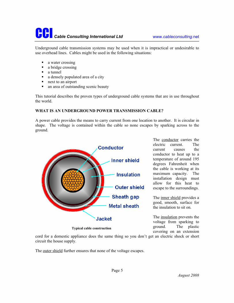
A power cable provides the means to carry current from one location to another. It is circular in shape. The voltage is contained within the cable so none escapes by sparking across to the ground.
The conductor carries the electric current. The current causes the conductor to heat up to a temperature of around 195 degrees Fahrenheit when the cable is working at its maximum capacity. The installation design must allow for this heat to escape to the surroundings.
The inner shield provides a good, smooth, surface for the insulation to sit on.
The insulation prevents the voltage from sparking to ground. The plastic covering on an extension
cord for a domestic appliance does the same thing so you don’t get an electric shock or short circuit the house supply.
The outer shield further ensures that none of the voltage escapes.
Typical cable construction

CCI Cable Consulting International Ltd www.cableconsulting.net
Page 6 August 2008
Depending on the cable type, the sheath gap is either filled with fluid or wrapped with swellable tapes to prevent the flow of water along the cable if it is damaged.
The metal sheath keeps the cable completely sealed, it prevents water from entering the cable and, in some types of cable, it prevents the filling fluid from escaping from the cable. The metallic sheath also has some important electric uses.
When included in the design of a cable, the jacket prevents the metal sheath from being corroded by water and salts in the surrounding soil. It is also used to insulate the metal sheath from ground, something that is important in the electric design of a system.
Cables can be manufactured in long lengths of several miles but can only be transported by road or rail in comparatively short lengths (1500 – 2000 feet, typically). A difficult installation terrain, such as a steep or winding route, may mean it is only practical to install short lengths.
The cables are transported from the factory to the construction site on large and heavy reels.
The reel lengths are joined together end to end by connectors called joints (sometimes called splices). These and cable terminations (sometimes called potheads) are described in more detail in the next section.
The main requirements of a power cable are reliability and safety. The cables are installed underground in a hostile environment and are inaccessible for visual inspection during their service lives. A cable system is normally designed to have a prospective life of 40 years.
Reels of cable are transported by large trucks
CCI Cable Consulting International Ltd www.cableconsulting.net
Page 7 August 2008
UNDERGROUND POWER CABLE ACCESSORIES
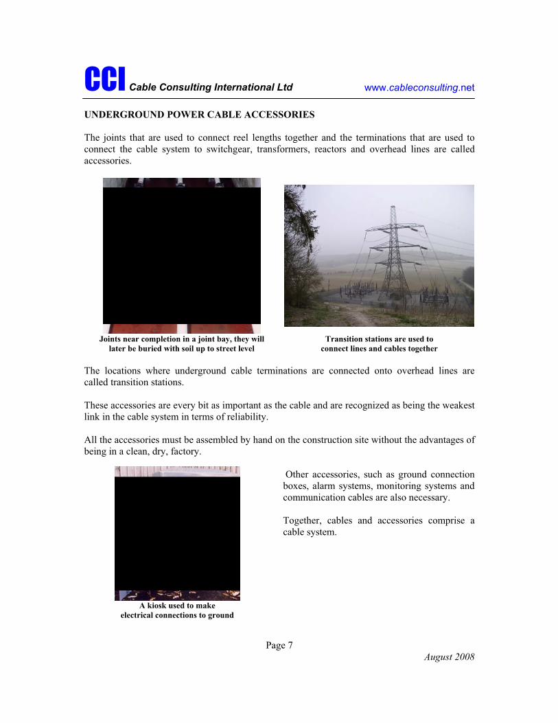
The joints that are used to connect reel lengths together and the terminations that are used to connect the cable system to switchgear, transformers, reactors and overhead lines are called accessories.
Joints near completion in a joint bay, they will later be buried with soil up to street level
Transition stations are used to connect lines and cables together
The locations where underground cable terminations are connected onto overhead lines are called transition stations.
These accessories are every bit as important as the cable and are recognized as being the weakest link in the cable system in terms of reliability.
All the accessories must be assembled by hand on the construction site without the advantages of being in a clean, dry, factory.
Other accessories, such as ground connection boxes, alarm systems, monitoring systems and communication cables are also necessary.
Together, cables and accessories comprise a cable system.
A kiosk used to make electrical connections to ground

CCI Cable Consulting International Ltd www.cableconsulting.net
Page 8 August 2008
WHAT ARE THE DIFFERENT TYPES OF TRANSMISSION CABLE SYSTEMS?
With the exception of a very small number of special circuits operating at 525kV, 345kV is the highest voltage for underground cables in the USA. Underground circuits at 345kV require advanced technology and each individual circuit must be custom designed and manufactured to suit the particular application. These cable systems cannot be purchased “off the shelf”.
Several different types of cable systems are in use throughout the world. Each system has advantages and disadvantages. For any given project, the most appropriate type of system must be selected by a utility after they have taken due account of their own technical and commercial requirements together with the views of the general public, land owners, local and state government, and other interested parties.
In this section the various types of cable systems are described and their main advantages and disadvantages are given. Where systems are not suitable for use at 345kV, this is indicated.
High Pressure Fluid Filled Systems
High pressure fluid filled is usually shortened to HPFF.
Here the three individual cables, called cores, necessary to form a circuit are installed in a steel pipe.
The pipe is first installed in lengths of up to 40 ft and these are welded together in sections that are typically 1500ft long. The three cables are then pulled into the pipe.
The joints that are necessary to join individual reel lengths together are installed in chambers in the ground called splicing vaults that are up to 30 feet long.
At the end of the process, the pipe is filled with a filling fluid and is then pressurized with pumps to around 200 pounds per square inch to achieve full insulation strength.
The key elements of each HPFF cable core are:
Conductor: This is made from many small copper or aluminum wires that are twisted together.
Insulation and shields: Many layers of thin tapes measuring less than one hundredth of an inch thick and less than one inch wide are wound onto the conductor in the factory. The layers of tape are applied until the insulation is around one inch thick. Carbon or metalized paper tapes are used as shields to maintain the circularity of the conductor and around the outside of the
CCI Cable Consulting International Ltd www.cableconsulting.net
Page 9 August 2008
insulation to contain the electric field within the insulation. Metal and plastic tapes are also applied over the outer shield.
Two types of insulating tape are available:
high quality paper that has been washed, treated and dried to remove any impurities and moisture or a sandwich of paper-polypropylene-paper (PPP). Polypropylene is a plastic with good electric, mechanical and temperature capability.
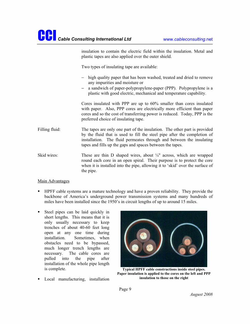
Cores insulated with PPP are up to 60% smaller than cores insulated with paper. Also, PPP cores are electrically more efficient than paper cores and so the cost of transferring power is reduced. Today, PPP is the preferred choice of insulating tape.
Filling fluid: The tapes are only one part of the insulation. The other part is provided by the fluid that is used to fill the steel pipe after the completion of installation. The fluid permeates through and between the insulating tapes and fills up the gaps and spaces between the tapes.
Skid wires: These are thin D shaped wires, about ¼" across, which are wrapped round each core in an open spiral. Their purpose is to protect the core when it is installed into the pipe, allowing it to ‘skid’ over the surface of the pipe.
Main Advantages
HPFF cable systems are a mature technology and have a proven reliability. They provide the backbone of America’s underground power transmission systems and many hundreds of miles have been installed since the 1950’s in circuit lengths of up to around 15 miles.
Steel pipes can be laid quickly in short lengths. This means that it is only usually necessary to keep trenches of about 40-60 feet long open at any one time during installation. Sometimes, when obstacles need to be bypassed, much longer trench lengths are necessary. The cable cores are pulled into the pipe after installation of the whole pipe length is complete.
Local manufacturing, installation
Typical HPFF cable constructions inside steel pipes. Paper insulation is applied to the cores on the left and PPP
insulation to those on the right

CCI Cable Consulting International Ltd www.cableconsulting.net
Page 10 August 2008
and maintenance expertise is readily available in the USA.
Steel pipes provide good, but not perfect, mechanical protection to the cable cores in the event of a ‘dig-in’ by a contractor digging up the roadway.
Steel pipes reduce the magnetic field effects that are generated by the cable cores.
The splicing vaults that are used to house the cable joints allow access to the joints for maintenance.
Long circuit lengths can be easily tested during circuit commissioning. Suitable test equipment is readily available in the USA.
Cable cores can be pulled out and replaced through the splicing vaults without the need to dig up the road.
Main Disadvantages
If a leak occurs in the steel pipe, fluid will leak out into the surrounding soil. (Monitoring systems can be used to give an early indication of the presence of a leak).
The filling fluid is at high pressure, it is stored in large reservoirs situated at various points along the cable route and can flow easily and quickly to the point of any leak.
Steel pipes will corrode if they come into contact with water and salts in the soil, just like a car kept at the coast will rust quickly. If the protection over the surface of the pipes is damaged, corrosion is likely to occur and, eventually, the corrosion will travel through the pipe wall and result in a fluid leak. Special equipment is necessary to reduce the risk of corrosion. Corrosion is seldom a problem in a properly designed and installed system.
Cable cores are free to move and slide within the steel pipe. Special design measures must be taken on routes with steep slopes in order to prevent cable damage. The severity of a slope may mean that a HPFF system can not be used at all.
Some North American utilities are now installing XLPE systems in preference to HPFF at transmission voltages up to 345kV. If this trend continues the availability of HPFF spares and expertise could become a longer term problem.
High Pressure Gas Filled Systems
High pressure gas filled is usually shortened to HPGF.
HPGF systems are similar to HPFF systems with the key difference being that the steel pipe is filled with nitrogen gas at 200 pounds per square inch rather than a filling liquid.
CCI Cable Consulting International Ltd www.cableconsulting.net
Page 11 August 2008
Main Advantages
A leak of nitrogen gas from the steel pipe has a far lower environmental impact than a leak of filling fluid.
Nitrogen gas is readily available and does not require any special formulation.
Nitrogen gas is non-flammable so there is not a fire risk if a cable system is installed in a tunnel or substation.
Main Disadvantage
An HPGF system is relatively weak electrically (because the nitrogen gas is not as good an insulator as fluid) and so HPGF systems are limited to voltages of 230kV and under. They are not suitable for 345kV so this tutorial will not consider these further. Dropping the power transmission voltage to 230kV or below is not usually a practical option as this would increase the current to be carried by 50% and twice the number of cables would be required to carry the same amount of power. The power transmission would be less efficient.
Self Contained Fluid Filled Systems
Self contained fluid filled is usually shortened to SCFF cable.
SCFF cables are sometimes also called low pressure fluid filled cables (LPFF).
Three single core cables are necessary to form a circuit.
The cables are buried directly in the ground.
For installation, a trench at least as long as the cable reel length is excavated and the cables are individually pulled into the trench. The open trench may be 1500 to 3000ft long.
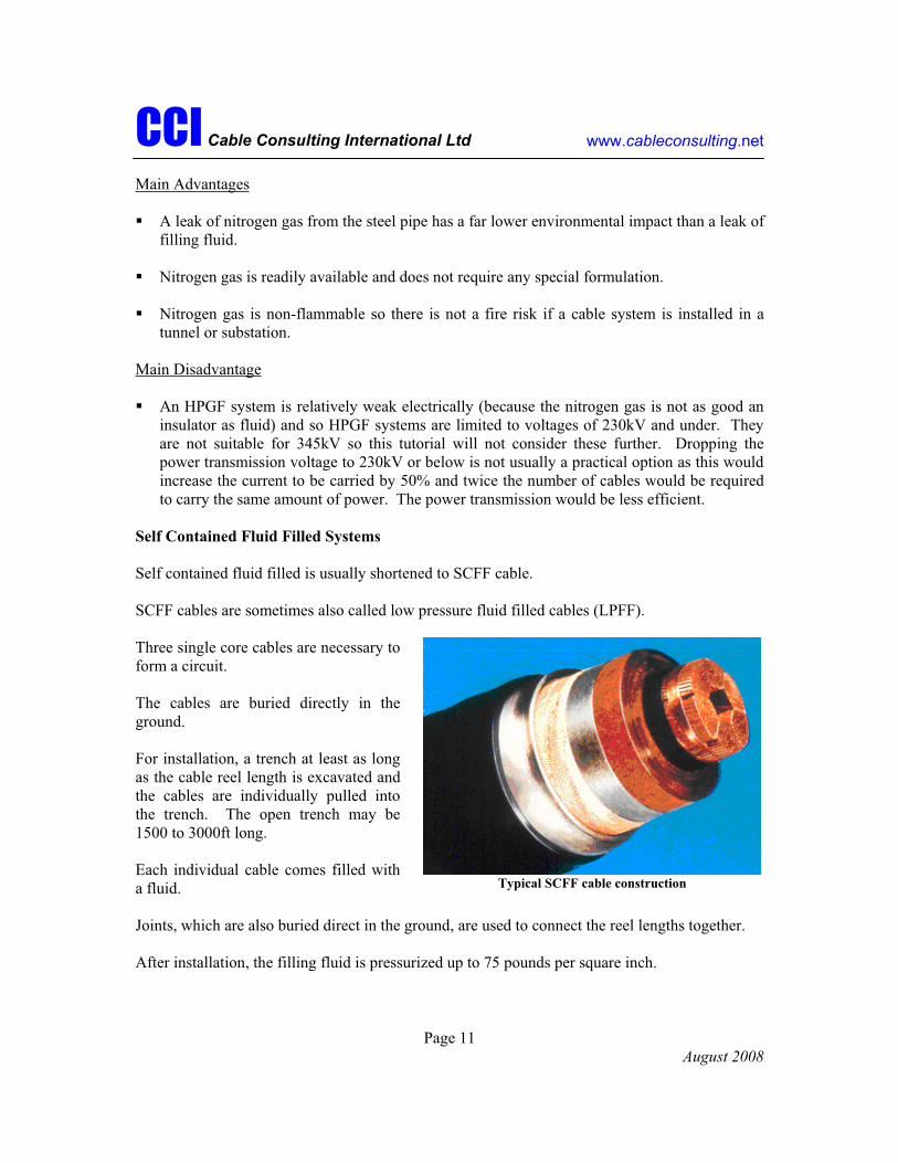
Each individual cable comes filled with a fluid.
Joints, which are also buried direct in the ground, are used to connect the reel lengths together.
After installation, the filling fluid is pressurized up to 75 pounds per square inch.
Typical SCFF cable construction

CCI Cable Consulting International Ltd www.cableconsulting.net
Page 12 August 2008
The key elements of each SCFF cable are:
Conductor: This is similar to the conductor used in HPFF cables. The main difference is that a hole, about ½" in diameter, is present in the center of the conductor to allow the filling fluid to flow from one end to the other when the cable heats and cools.
Insulation and shields: These are similar to the insulation and shields used in HPFF cables. As with HPFF, the paper or PPP tapes are only one part of the insulation. The other part is provided by the filling fluid that is contained within the cable.
Metal sheath: This is a tube made from lead or aluminum that is applied over the insulation by means of a process called extrusion. The purpose of the sheath is to prevent the filling fluid from leaking out of the cable and to prevent air or water from leaking into the cable. It also has several important electric functions.
Jacket: This is a tube made from polyethylene or PVC that is applied over the metal sheath by an extrusion process.
Main Advantages
SCFF cable systems are a mature technology and have a proven reliability. Outside of America, they provide the backbones of the power transmission systems in most European, Middle Eastern and Asian countries. Many thousands of miles have been installed since the 1960’s.
SCFF systems are buried direct in the ground. This and the use of special anchor joints means that cable movement on steep slopes can be prevented.
The three cables can be spaced apart in the ground giving improved heat dissipation to the ground surface.
Long circuit lengths can easily be tested during circuit commissioning. Suitable test equipment is readily available in the USA.
Main Disadvantages
If a leak occurs in the metal sheath, fluid will leak out into the surrounding soil. (Monitoring systems can be used to give an early indication of the presence of a leak).
CCI Cable Consulting International Ltd www.cableconsulting.net
Page 13 August 2008
At the higher transmission voltages, where conductor sizes tend to be large and generate high mechanical forces, SCFF systems are not suitable for installation inside long lengths of ducts or pipes as the metal sheath may fatigue and fail.
Long lengths of trench must be open for longer periods. Long trench lengths present a safety hazard particularly for trenches dug in busy streets. Also, traffic disruption may occur.
Fluid reservoirs must be installed at regular intervals along the route to allow for expansion and contraction of the filling fluid.
Corrosion of the cable sheath will result in fluid leaks so regular maintenance testing is necessary, requiring the circuit to be switched out of service.
The spacing necessary to allow good heat dissipation may result in a wider trench and in higher magnetic fields.
Special grounding techniques are necessary. These require connection boxes or kiosks to be installed. They must be maintained regularly. The boxes and kiosks must be designed and located to protect the public from the effects of a cable system fault.
SCFF cable systems are not manufactured in the USA and are not regularly installed by USA based contractors. There is, therefore, very little specialist installation and operational expertise available within the USA.
Many European and Asian manufacturers of SCFF systems have switched from the production of SCFF to XLPE cable systems. The last large scale production facility in Europe is now being closed. The availability of SCFF spares and expertise in the future is likely to be a problem.
Cross Linked Polyethylene Systems
Cross linked polyethylene is usually shortened to XLPE.
XLPE cables are also called extruded or solid insulation cables. A technical term used to describe the insulation is ‘dielectric’.
Three single core cables are necessary to form a circuit.
The cables may be buried directly in the ground or pulled into individual non metallic pipes or ducts.
For installation, either a trench at least as long as the cable reel length is excavated and the cables are pulled into the trench, or individual ducts, usually manufactured from a plastic material, are laid in short lengths and joined together before the cables are pulled into them.

CCI Cable Consulting International Ltd www.cableconsulting.net
Page 14 August 2008
Each individual cable is dry inside and is not filled with a fluid.
Joints are used to connect the reel lengths together and are located in splicing vaults, or encased in conduit or buried direct in the ground.
XLPE systems have a proven reliability at voltages up to 161kV. At higher, power transmission, voltages, their use is relatively recent.
The key elements of each XLPE cable are:
Conductor: This is similar to the conductor used in HPFF cables.
Insulation and shields: The XLPE insulation is extruded over the conductor together with the inner (underneath) and outer (over) shields by means of a process called triple extrusion. Squeezing toothpaste out of a tube is a form of extrusion. Some grocery bags that are supplied by supermarkets are made from polyethylene. The crosslinking process links individual polyethylene molecules together and has the effect of increasing the melting point of the insulation. This allows the XLPE cable to operate at the same higher temperature as HPFF and SCFF cables and thus carry a similar power level.
Metal sheath: This is similar to the metal sheath used in SCFF cables. As the metal sheath does not have to contain a pressurized filling fluid, a number of alternative, less robust, types of metal sheath are available for some applications.
Jacket: This is similar to the jacket used in SCFF cables.
Main Advantages
The insulation is electrically efficient, so relatively long underground circuits can be installed which helps to keep the cost down.
XLPE systems don’t contain fluid so the environmental effects of leaks are not a problem. Fluid system maintenance is not necessary.
Typical XLPE cable construction

CCI Cable Consulting International Ltd www.cableconsulting.net
Page 15 August 2008
XLPE systems do not burn as readily so there is a reduced risk of fire spread in tunnels and sub-stations.
There is now a greater number of suppliers with a manufacturing capability for 345kV XLPE cable than those who manufacture other cable types.
Main Disadvantages
Reliable, long term, service experience is still being proven. At power transmission voltages, XLPE cable systems were developed after the other types of systems discussed in this tutorial. The first long length system at 345kV or at higher voltages was not commissioned until the mid 1990’s. The circuit length was 7.5 miles.
XLPE technology was held back by difficulties in producing and assembling reliable accessories (joints and terminations). Different designs and materials are in use around the world and manufacturers are still improving them. As with other cable types, the accessories are recognized as the weakest link.
In the event of undetected damage to the metal sheath, moisture can enter the XLPE insulation and weaken it. Premature cable failure is likely.
XLPE cables are larger in diameter as a thicker layer of insulation is required. Reel lengths tend to be shorter and sometimes the number of joints has to be increased.
345kV XLPE cables and accessories are not yet manufactured in the USA, although this is expected to change. The expertise of USA based installation contractors is growing with time.
International standards require long term proving tests to be carried out on each new design of XLPE cable system. These can be up to one year long and thereby increase project lead time.
The manufacture of XLPE cable is slower than other types and so longer project lead times are required.
Cable circuits are tested at a high voltage before being energized. Special equipment comprising an HV AC voltage generator is required to test an XLPE cable system, this being significantly larger and more complex than equipment used for other cable types.
The installation of self-contained XLPE cables in three plastic ducts instead of one steel pipe increases the magnetic field effects and complexity of the grounding equipment compared to HPFF systems.

CCI Cable Consulting International Ltd www.cableconsulting.net
Page 16 August 2008
Ethylene Propylene Rubber Systems
Ethylene propylene rubber is usually shortened to EPR.
EPR cables are also called extruded or solid insulation cables.
Three single core cables are necessary to form a circuit.
The cables are either buried directly in the ground or pulled into non-metallic pipes.
For installation direct in the ground, a trench at least as long as the cable reel length is excavated and the cables are pulled into the trench.
Each individual cable is dry inside and is not filled with a fluid.
Joints, which are either buried direct in the ground or installed in splicing vaults, are used to connect the reel lengths together.
Main Advantages
EPR systems are more resistant to water and can be exposed to water for a longer time without a metallic sheath.
EPR cable is more flexible and can be bent into tighter locations without damage.
EPR systems can carry a higher overload under emergency situations with less risk of damage.
Main Disadvantage
EPR is electrically less efficient than XLPE insulation and so cable systems are usually limited to voltages of 150kV and under. They are not suitable for 345kV so will not be considered further in this tutorial.
NEWER TYPES OF TRANSMISSION SYSTEMS
Newer types of transmission systems, which are still at the proving stage, are gas insulated lines (GIL) and superconducting cables.

CCI Cable Consulting International Ltd www.cableconsulting.net
Page 17 August 2008
A GIL system comprises three aluminum alloy pipes each some 2 feet in diameter and 40 feet long. A solid tubular aluminum conductor is inserted into each pipe. Many pipes are then
welded or bolted together. GIL has the advantage that higher levels of power can be carried over longer distances because of the larger size of the conductor and pipe. The pipes can be installed above ground on stilts, in a tunnel or they can be direct buried underground. After installation, the pipe is filled with an insulating gas.
To date, little long length GIL has been installed worldwide. These installations have been above ground in power plants or in tunnels. Only short, trial, lengths have been installed direct buried underground.
Underground, long length GIL systems do not have a proven reliability and service life.
Above ground, GIL systems present a considerable visual impact. Where GIL is direct buried in the ground, there is concern over the additional mechanical stresses that will arise in the aluminum pipes. Aluminum is a metal that corrodes easily and the protection of direct buried pipes is extremely important.
Superconducting cable systems use the property that at low temperatures some materials have no electric resistance. This allows high levels of current to flow in a smaller conductor. These systems have to be kept extremely cold by having liquid helium or nitrogen pumped through them at a temperature down to as low as minus 450 degrees Fahrenheit and they have to be thermally insulated from their surroundings within a vacuum filled tubular layer. Superconducting transmission systems are at the prototype stage with some short length service connections recently installed and under evaluation in the US. The superconducting system is a high technology solution which is still evolving and which does not yet have a proven reliability and service life.
HOW ARE CABLE SYSTEMS INSTALLED?
HPFF Systems
First of all the steel pipes are installed in the trench. The pipes are installed at a depth of around 4 feet. Each pipe section is about 40 feet long and the individual sections are welded together and x-rayed to ensure the quality of the weld.
GIL installed on short stilts (diagrammatic representation only)

CCI Cable Consulting International Ltd www.cableconsulting.net
Page 18 August 2008
Pipe installation moves progressively along the route and it is only necessary to keep a short section of trench open at any one time. Trench lengths of 200 feet are possible. This minimizes disruption to pedestrians, traffic, landowners and so on.
The pipe trench is either part filled with concrete, soil that was removed from the trench, or with a special material, called thermal backfill, which helps remove the heat from the cables.
After installation of the pipe, the three reel lengths of cable core are pulled into the pipe together. The inside of the pipe and the welded pipe joints must be smooth so that the skid wire protected cable cores can slide easily and prevent damage to the cores.
Splicing vaults can measure up to 8 feet wide, 8 feet deep and up to 30 feet long and are constructed to allow individual cable reel lengths to be connected together.
The joints that are used to connect the reel lengths together are installed in the splicing vaults. A larger steel casing is then welded to the steel pipes thereby sealing the joints into the pipe system.
At each end of the route, terminations are connected onto the ends of the three cable cores to allow them to be connected to switches, transformers or overhead lines.
Pumping stations are positioned periodically in long routes to house fluid reservoirs and associated pumping equipment. These reservoirs permit thermal expansion and contraction of the fluid.
Filling fluid is pumped into the steel pipe after completion of joint and termination installation and is pressurized to around 200 pounds per square inch. In some applications the fluid is circulated to cool hot spots along the cable.
Finally, the circuit is tested and is put into service.
SCFF Systems
SCFF systems are most suited to direct burial in the ground.
A trench length at least equal to the reel length, around 1,500 – 2,000 feet, must be open. Trenches are typically 3-4 feet deep and 3-4 feet wide. Wooden boards or steel shuttering are installed along the trench length to prevent collapse.
Three cables are pulled in one after the other. Often a technique, called ‘bond pulling’, is necessary whereby
Open cable trench

CCI Cable Consulting International Ltd www.cableconsulting.net
Page 19 August 2008
each cable is supported by a tensioned wire rope as it is pulled in so that it is not stretched or crushed.
After the cables are pulled in, the trench is filled with either the soil that was removed or with thermal backfill, if help to remove heat from the cables is necessary.
Cable joints are then installed in pits containing a concrete base. These pits are sometimes called joint bays and typically measure 9 feet wide, 6 feet deep and 24 feet long. A large tent or building is erected over the pit. A clean working environment is established and the inside may be air conditioned.
Joint bays cannot be backfilled until two consecutive cable section lengths have been pulled in and connected together. The joints have to be sealed inside a waterproof casing and also protected from loads arising from the soil and road surface.
Terminations are connected to the cable ends at the ends of the route in order to allow them to be connected to switches, transformers or overhead lines.
SCFF systems operate at a maximum pressure of 75 pounds per square inch. Sectionalizing joints, called stop joints, are used to limit fluid pressures along a steep route. These joints also anchor the cable system mechanically in order to prevent movement downhill.
A buried joint bay during the backfill operation
115kV cable system terminations

CCI Cable Consulting International Ltd www.cableconsulting.net
Page 20 August 2008
Fluid reservoirs to permit expansion and contraction of the filling fluid must be buried in the ground next to stop joints and at the ends of the route.
Finally, the circuit is tested and is put into service.
High voltage test set connected to SCFF terminal
XLPE Systems
XLPE systems up to 345kV are suited both to direct burial in the ground and for installation in ducts (one cable) and pipes (three cables).
Installation of direct buried XLPE systems is similar to installation of SCFF systems.
As with other cable types joints and terminations are the weakest link and must be installed in a carefully controlled ultra-clean environment. XLPE joints are highly complex to manufacture and special care and techniques are necessary during assembly.
Anchor joints are required to secure the cable system from moving in special situations.
Transition joints are becoming available that will permit new XLPE cable to be electrically connected to existing types of fluid filled cable, whilst completely segregating the fluid filling.
Some designs of XLPE termination must be filled with insulating oil.
Pit housing fluid feed tanks
Connecting XLPE cables together in an ultra-clean environment within a
buried joint bay

CCI Cable Consulting International Ltd www.cableconsulting.net
Page 21 August 2008
It may be necessary to insert intermediate substations in longer circuits to separate them into short lengths and so permit the cable system to be voltage tested prior to commercial operation.
MAINTENANCE AND REPAIR
The technology used for HPFF and SCFF systems is mature and well proven. Provided systems are designed, manufactured, installed and maintained properly, a long, reliable, service life should follow. XLPE systems are still accumulating service experience. Manufacturers are investing heavily into XLPE systems and this gives confidence that, in time, designs should evolve and reliability should match that of HPFF and SCFF systems.
Maintenance
Regardless of the type of cable system, routine maintenance is necessary to keep it in as good a condition as possible. This will help to prevent unexpected failures.
Each system has its own specific, detailed, maintenance requirements but these can be generalized as follows:
A regular patrol along the cable route to look for evidence of anything that may indicate the system has been or is likely to be damaged. Roadworks by another utility is a good example.
A regular inspection of all exposed pipework and pressure gauges to look for any signs of fluid leakage.
Regular testing of ground bonding connections, alarm connections, corrosion protection systems (including cable jackets) and surge limiters that protect the cable system from lightning strikes and other abnormal electric events.
Repair
In the event of a failure of a cable system component, a system repair will be necessary.
Failure of a minor item may mean that a repair can be carried out while the circuit remains in service.
Failure of a major component, such as the cable itself, the metal sheath, the jacket, a joint, a termination or a grounding connection will mean that the system must be taken out of service to permit the repair to be carried out safely.
Fluid pipe and gauge inspection

CCI Cable Consulting International Ltd www.cableconsulting.net
Page 22 August 2008
Fault location and repair times will range from one week (a jacket repair, for example) through several weeks to more than a month (a failed cable or joint, for example).
In the event of a failure, a utility must do everything reasonable to limit further system or environmental damage.
The failure must first be located. Electronic location techniques are used as the cable system is buried and cannot be inspected visually. This can take several days. Any other adjacent equipment (transformers, switches, etc) must also be examined to check for damage.
After successful location, the most appropriate repair solution must be established. This may mean that a specialist from the supplier of the cable, joint or termination must visit the site.
Each cable system is designed specially for each utility and a supplier is not likely to have spare parts in stock. Manufacturing times are a few months and so each utility should hold its own set of spares. Typically a utility will hold a spare reel of cable, two spare joints and one spare termination.
Skilled personnel must be available to carry out the repair.
A transmission cable system is designed to have a service life of 40 years. It therefore follows that spare parts, materials and tools must be available over the service life. In selecting a particular cable system type a utility must ensure, as far as they can, that direct spares or suitable substitutes remain available.
HOW DO CABLE SYSTEMS AFFECT ME?
As part of the project planning process, the utility will have negotiated the right to install the cable circuit with local authorities, land owners, etc. Often, in the countryside, a dedicated right-of-way will be granted that gives a utility the right to install cables or overhead lines and to access them for maintenance and repair purposes. The right-of-way is effectively a continuous path of land that is leased to the utility.
In towns and cities, it is not usually practical to dedicate a right-of-way to a utility as other utilities often have to install their services in close proximity and the public need to be given access to roadways after the completion of installation.
During installation, trenches will have to be excavated. Depending on the number of circuits being installed, an access width of up to 36 feet may be necessary. Traffic flow may be disrupted and, on some occasions, partial or total temporary street closures will be necessary.
Also, as part of the project siting process, an environmental impact analysis is typically performed. This will have covered installation, in-service operation and repair and maintenance of the cable system.

CCI Cable Consulting International Ltd www.cableconsulting.net
Page 23 August 2008
During Installation
During installation as much work as possible, such as trench excavation, splicing vault construction and the storage of excavated soil, will be performed within the right-of-way or the area negotiated with a town or city authority. However, additional areas will probably be required and these will be negotiated on a case by case basis.
At all times during installation, public safety is paramount and, by means of a risk analysis process, all risks will be identified, analyzed, quantified and measures adopted to minimize each risk and its effects. A typical example is the construction of a splicing vault. This will be protected by crash barriers, signs warning about the presence of the splicing vault will be posted and the splicing vault location will be lit at night. In some circumstances, security guards will be employed.
Installation will typically progress at a rate of about one mile per month and will move progressively along the route so not all parts will be affected all of the time.
The key areas with the greatest impact are as follows:
Increased construction traffic. Large, heavy trucks will need to access the construction site. Drivers will be instructed to only use approved access routes. Wheel washing and measures to minimize dust will be employed. In particular, increased traffic will result from
Trucks carrying excavating machines. Trucks carrying cable reels, transformers and switches. Trucks taking away excavated soil and returning with concrete and thermal backfill. Cars and pickups carrying engineers and construction workers.
Three reels of cable are parked in the street ready to be pulled into a steel pipe
Installation of ducts to house the cables that will cross the river

CCI Cable Consulting International Ltd www.cableconsulting.net
Page 24 August 2008
Open trenches and splicing vaults or joint bays If a HPFF pipe or XLPE duct system is being installed, trenches up to 200 feet will be opened. Depending on trench length, excavation, pipe installation and backfill of 1-4 trenches can take place in less than a day. Work will proceed along the route by completing adjacent short trench sections.
Each splicing vault will be installed in less than a week. Cable pulling of three lengths of 1,500- 2,000ft of cable will take place in less than a day. Jointing work will continue inside the splicing vault for around 2-3 weeks.
If a SCFF or XLPE buried direct system is being installed, trenches of up to 2000 feet will have to be opened in one operation. The excavation, cable laying and backfilling cycle takes about 2 weeks. Each vault will have to be open for joint assembly and backfill for an additional period of 2-3 weeks.
Once trenches and splicing vaults have been filled in, the road surface will be ‘reinstated’ to its original condition. Reinstatement is usually a two stage process; temporary reinstatement to allow the filling to settle followed by permanent reinstatement which can be several months later depending upon the road surface type.
Access to vehicular traffic and pedestrians. Access will inevitably be restricted during construction of those parts of the route passing alongside and underneath roads and sidewalks. On a long length route of tens of miles the work may occupy a period of many months to over a year. Work will proceed at different locations along the route at the same time. The schedule of work and necessary measures are agreed in advance with the appropriate State, City and Town Traffic Departments. Examples of the impacts and measures that may be taken to ease access are:
An open trench will be fenced off and lit at night. The trench will be typically 3-4 feet wide for HPFF pipe and XLPE duct installations comprising 3-6 cables and also for XLPE and SCFF buried direct installations comprising 3 cables. For XLPE and SCFF direct buried installations of 6 cables, either the trench width will be
Temporary trench reinstatement

CCI Cable Consulting International Ltd www.cableconsulting.net
Page 25 August 2008
increased to 4-6 feet or a second trench excavated. Sufficient additional road width must be allowed to permit the excavated soil to be stored, removed and replaced. Access must also be provided for the excavation machines and trucks. This is likely to require that one lane of the road be closed and temporary traffic lights be used to control traffic flow.
When two trenches are to be installed under opposite sides of the road, one section length of pipes, ducts or cables will be completely installed and the road surface reinstated before the trench on the opposite side is opened.
Typically, vehicles can not be parked along the roadside during trenching operations.
The time that a trench may be open depends upon a number of factors, including the weather. The presence of other buried services in the ground, such as water pipes, gas pipes, water drains, communication cables and domestic electricity cables will require that the trench be excavated to a greater depth using hand tools. The presence of a high water table will require that the trench be continuously pumped dry. Loose, running ballast will require special measures to support the trench walls. Rock and concrete will require special cutting and drilling equipment.
In some locations it may be necessary to lay the cable close to, or under, a sidewalk. A fenced off safe passage is then provided for pedestrians.
The crossings of major road intersections and civil constructions such as bridges and tunnels will require special arrangements. The trench may be opened at night requiring that either the lane or road be temporarily closed. One possibility is to lay pipes or ducts and to quickly reinstate the road surface such that the cables can be pulled under the intersection at a later date without the need to interrupt traffic.
At certain intersections steel plates may be laid to bridge the trench.
Access to domestic and public premises for vehicles and pedestrians may be provided across the trench by a temporary crossing if access is to be restricted for a prolonged period.
Ducts being positioned in a deep trench before pouring concrete

CCI Cable Consulting International Ltd www.cableconsulting.net
Page 26 August 2008
Special measures are taken to provide access for emergency vehicles to public premises such as hospitals, schools and fire and police departments.
In some special circumstances, as an alternative to temporary trench crossings, unrestricted access can be achieved by the use of pipe-jack tunnels, miniature tunnels or by directional drilling. However these techniques have technical limitations dependent on the location and type of cable. The installation of joints in either splicing vaults (HPFF pipe and XLPE duct cables) or bays (XLPE and SCFF buried direct cables) requires the excavation of a wider and deeper hole than the trench. The construction time for the splicing vault and the installation time for the joints is significantly longer than for the trench and cables. Wherever possible a location for the splicing vault is chosen to reduce the disruption to vehicular and pedestrian access.
In applications where two parallel configurations of six cables are required, combinations of double length splicing vaults and double width splicing vaults may be selected to separate the joints for maintenance purposes.
To reduce site construction time the splicing vaults may be prefabricated in pre-cast concrete and transported to site and lowered into position using large trucks and cranes. The traffic flow may require to be halted during this activity.
Jointing activities will take 2-3 weeks. It is usual during this time to cover the two access positions in the roof of the splicing vault chamber by small tents, small temporary buildings or special vehicles. A joint bay in a buried direct system has to remain open for this period and it will be necessary to completely weatherproof it with a large sealed tent, large temporary building or a custom designed shipping container. An additional period of 1 week may be required to remove the temporary building from the bay and to reinstate the road surface. It will be necessary for the specialist support vehicles to park along the road during the jointing period. The support vehicles will also include electricity generators for air conditioning equipment, pumps, lighting and power tools as well as washing and changing facilities for the jointers.
Ducts entering a single, pre-cast concrete splicing vault
CCI Cable Consulting International Ltd www.cableconsulting.net
Page 27 August 2008
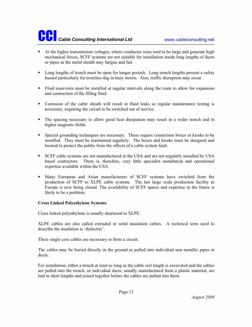
During cable installation it will be necessary to park three large trucks next to the splicing vaults and use a crane to lift the large and heavy cable reels onto axle stands that will permit them to rotate. Traffic flow may require to be halted during this activity. Powered winches are located at the next splicing vault or joint bay to pull the three cables into position. A number of workers and vehicles are necessary during this activity, which will usually be completed within 1-2 days.
Construction work may be performed at night and covered with steel plates during the day.
Plants and animals. There is likely to be some disruption to the local ecosystem. Any plants or flowers that are covered by any preservation order will be identified and through consultation with the right representative bodies, a plan will be put into place to mitigate any environmental impact. The same is true for animals.
Noise from construction machinery. This may be minimized by the use of acoustic shielding where necessary.
Visual impact. This can be minimized by the use of appropriate screening.
In Service
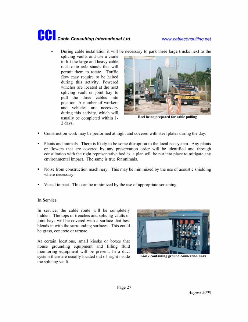
In service, the cable route will be completely hidden. The tops of trenches and splicing vaults or joint bays will be covered with a surface that best blends in with the surrounding surfaces. This could be grass, concrete or tarmac.
At certain locations, small kiosks or boxes that house grounding equipment and filling fluid monitoring equipment will be present. In a duct system these are usually located out of sight inside the splicing vault.
Reel being prepared for cable pulling
Kiosk containing ground connection links

CCI Cable Consulting International Ltd www.cableconsulting.net
Page 28 August 2008
The key areas with the greatest impact are as follows:
Visual impact. Apart from boxes or kiosks there will be very little visual impact along the length of the route. In the photograph, 12 SCFF transmission cables cross this farmer’s field in the UK.
Kiosks protected by a fenced enclosure can be seen in the middle of the field.
At the ends of the route in transition stations, where the terminations connect onto transformers, switches or overhead lines, secure fenced yards will be necessary.
Depending on the circuit configuration, it is possible that smaller yards will be necessary at one or two points along the route.
Boxes and kiosks. These will only be visible when it is not possible to house them underground. The electric design of SCFF and XLPE circuits requires that any accessories are connected to the cable system at no greater a distance than 30 feet. All boxes and kiosks will be of a strong steel construction and will be locked to prevent unauthorized access. They will be located in a position where accidental damage by the public is minimized.
Fluid leaks. The filling fluids contained in HPFF and SCFF cables are not listed in the Environmental Protection Agency’s hazardous waste regulations. They also do not trigger any of the four criteria (corrosivity, reactivity, ignitibility and toxicity) for determining the status of those wastes not specifically listed by the EPA.
One fluid, alkylbenzene contains a benzene ring. It is considered to have a low toxicity. A water soluble form of alkylbenzene is used in household detergents.
Only the fenced enclosure is evidence that 12 transmission cables cross this land
Transition stations where cable terminations are connected to
overhead lines

CCI Cable Consulting International Ltd www.cableconsulting.net
Page 29 August 2008
If ingested at full strength by humans, it can cause nausea. It is non-carcinogenic and has no adverse reproductive effects.
Cable filling fluid is classified as a non-indigenous substance by the State of Connecticut and the State has a formalized program to remediate releases. The Remediation Standard Regulations (RCSA 22a-133k-1, 22a-430) place a high level of scrutiny on the cleanup of contamination. The State also administers a permitting program to prevent future releases.
Cable systems are monitored so that the presence of a leak is indicated as early as possible.
It is in the best interest of all parties that HPFF and SCFF systems are designed and installed to be as leak tight as possible.
Magnetic fields. When power flows along an overhead line or underground cable conductor, an electric and a magnetic field are generated. In an overhead line both fields spread out from the conductors, and progressively reduce in strength as the distance from the conductor increases.
In a cable, the electric field is completely screened by the outer shield and the metallic sheath and does not spread out into the surrounding environment. Only the magnetic field spreads out. The magnetic field decreases in strength as the distance from the cable increases.
For SCFF and XLPE systems, the installation configuration of the cables has an effect on the magnitude of the magnetic field and how fast it drops off. The magnetic field strength at the ground surface can be reduced by burying the cables deeper and closer together.
Whenever practical the configuration that produces the lowest field will be used. It should be noted, however, that some configurations may severely restrict the cables’ capability to transfer sufficient power and may not be suitable.
Plants and animals. When carrying maximum power, the cable conductor reaches a temperature of around 195 degrees Fahrenheit. The temperature drops as the distance from the conductor increases but there will be some localized heating of the soil in the immediate vicinity of the cables. Such additional heating would normally have reduced to zero some 12 to 15 feet away from the cables.
Kiosk containing pressure gauges and fluid leak alarms
CCI Cable Consulting International Ltd www.cableconsulting.net
Page 30 August 2008
In some locations the local temperature increase may result in the moisture content of the surrounding soil decreasing, so some plants and animals may be affected by the temperature and a lack of moisture.
Noise from transition stations. Sometimes a low pitched ‘hum’ can be heard to come from transition stations when transformers are present. This effect is minimized by installing transformers on anti-vibration pads and by the use of acoustic baffles.
Risk of damage by contractors and other utilities. There is a risk to cable circuits from dig-ins. Detailed ‘as installed’ route plans will be made available to a central agency (“Call Before You Dig” in Connecticut) so the location of cables can be identified in the future.
Warning signs may be placed at discrete locations.
Portable scanners are available for use by contractors and are called Cable Avoidance Tools. These detect the magnetic field from a cable circuit and warn of its presence.
If someone commences digging without taking sensible precautions, they will find that the cable circuits are covered with warning tapes, steel plates or concrete slabs that state ‘Caution Electricity’ or something similar.
They may also find that the cable trenches have been filled with a type of concrete for heat dissipation reasons.
The likelihood of from dig-in damage is therefore small.
Plowing restrictions on farmland. Cables buried across farmland may restrict the depth to which a farmer may operate a plough. Prior to installation, the depth of the cables would have been agreed with the farmer.
During Maintenance and Repair
Regular patrols are necessary to check the cable route for damage and to check all HPFF and SCFF connections are leak tight. Access to boxes or kiosks will be necessary but as checks are carried out annually the impact is likely to be small.
Transmission circuit warning sign
Protection and warning signs over buried cables

CCI Cable Consulting International Ltd www.cableconsulting.net
Page 31 August 2008
The impact will be similarly small during routine maintenance tests on the cable system’s grounding connections and during minor system repairs.
In the event that a major system repair becomes necessary, such as a failed cable or joint, significant disruption in the vicinity of the failure site can be expected. Localized trench, splicing vault or joint bay excavations may be necessary and, in some circumstances it will be necessary to install a new length of cable. For HPFF systems in pipes and XLPE systems in ducts this can be achieved without trench excavation as the new cable core can be pulled into the existing pipe or duct.
TUTORIAL SUMMARY
Underground cable transmission systems may be used when it is impractical or undesirable to use overhead lines, however there are technical limitations that prevent underground cables carrying power over long distances.
Transmission cables are installed underground in a hostile environment where they are inaccessible for visual inspection and easy maintenance. The main cable requirements are therefore safety and reliability during a long service life.
A choice of cable types exists for transmission voltages up to 345kV. At this high voltage level the cable systems are custom designed to suit each application and the highest levels of technology and quality are required.
XLPE (extruded crosslinked polyethylene) is the newest type of transmission cable. XLPE is now being selected as the preferred cable type for the majority of applications worldwide. The main advantages are that it is electrically efficient and does not contain fluid. Service experience is still being accumulated to demonstrate reliability and service life. In particular the accessories that connect and terminate the XLPE cable lengths, are evolving in design to improve performance. The more mature and highly evolved cable types, with a demonstrated reliable service life, are now being superseded. Examples are HPFF cable (high pressure fluid filled) installed in a steel pipe and SCFF cable (self contained fluid filled) installed directly in the ground.
Careful installation and protection of the cables is every bit as important as the cable design and manufacture, as the cables can initially be damaged during pulling in and jointing operations and later by third party dig-ins.
Some disruption to pedestrian and traffic flow and some effect to the environment is inevitable during the comparatively long construction period when trenches are dug and cables and joints are installed. However these can be reduced with responsive project planning and co-operation with the appropriate public bodies.

CCI Cable Consulting International Ltd www.cableconsulting.net
Page 32 August 2008
Regular maintenance in the form of diagnostic monitoring of the underground cable and visual inspection of the above ground equipment is important in reducing the need to re-excavate and repair the cable; the circuit outage times for which would be long.
Careful selection of the cable and installation type, the cable manufacturer and the installation contractor, together with good project management, will lay a sound foundation for a reliable and long service life.