BY ORDER OF THE AIR FORCE INSTRUCTION 33-107, … · MODIFIED USER TERMINAL ELEMENT (AWCP/MUTE),...
143
NOTICE: This publication is available digitally on the AFDPO/PP WWW site at: http://afpubs.hq.af.mil. COMPLIANCE WITH THIS PUBLICATION IS MANDATORY BY ORDER OF THE SECRETARY OF THE AIR FORCE AIR FORCE INSTRUCTION 33-107, VOLUME 4 1 November 2000 Communications and Information STRATEGIC AUTOMATED COMMAND CONTROL SYSTEM-DATA TRANSMISSION SUBSYSTEM (SACCS-DTS) OPERATION OF AIRCRAFT WING COMMAND POST/ MODIFIED USER TERMINAL ELEMENT (AWCP/MUTE), BASE COMMUNICATIONS PROCESSOR (BCP), P0RT EXPANSION PROCESSOR (PEP), AND SACCS DESKTOP TERMINAL (SDT) OPR: HQ AFSPC/SCMB (Mr. N. Schweisow) Certified by: HQ USAF/SCXX (Lt Col T. G. Pricer) Pages: 142 Distribution: F This instruction implements Air Force Policy Directive (AFPD) 33-1, Command, Control, Communica- tions, and Computer (C4) Systems, and is used in conjunction with Air Force Instruction (AFI) 33-107 Vol. 1, Strategic Automated Command Control System-Data Transmission Subsystem (SACCS-DTS) Soft- ware Configuration Management and Change Control; AFI 33-107 Vol. 2, Strategic Automated Com- mand Control System (SACCS-DTS) Network Security Program, and AFI 33-107 Vol. 3, Strategic Automated Command Control System (SACCS-DTS) Network Security Plan. The instruction provides general and specific instructions for operation of the Strategic Automated Command Control Sys- tem-Data Transmission Subsystem (SACCS-DTS) at Aircraft Wing Command Post (AWCP)/Modified User Terminal Element (MUTE) Communications Processor and Base Communications Processor (BCP). This instruction applies to Headquarters Air Combat Command (HQ ACC), Headquarters Air Mobility Command (HQ AMC), Headquarters United States Strategic Command (HQ USSTRATCOM), Headquarters Air Force Space Command (HQ AFSPC), their numbered air forces, and base-level users who operate SACCS equipment. It also applies to Air National Guard and United States Air Force Reserve units and members who use the Port Expansion Processor (PEP) and SACCS Desktop Terminal (SDT). Use this instruction to operate DTS equipment at High Frequency Single Side Band (HFSSB) sites. Air Force Directory (AFDIR) 33-303, Compendium of Communications and Information Terminol- ogy will explain other terms. Send recommended changes or comments to Headquarters Air Force Com- munications Agency (HQ AFCA/ITPP), 203 W. Losey Street, Room 1100, Scott AFB IL 62225-5222, through appropriate channels, using AF Form 847, Recommendation for Change of Publication, with an information copy to 625 th Missile Operations Flight, ATTN: SACCS Management Branch, 901 SAC Blvd Ste 2B23, Offutt AFB NE 68113-5540. The 625 th Missile Operations Flight is the office of collat-
Transcript of BY ORDER OF THE AIR FORCE INSTRUCTION 33-107, … · MODIFIED USER TERMINAL ELEMENT (AWCP/MUTE),...

NOTICE: This publication is available digitally on the AFDPO/PP WWW site at:http://afpubs.hq.af.mil.
COMPLIANCE WITH THIS PUBLICATION IS MANDATORY
BY ORDER OF THE SECRETARY OF THE AIR FORCE
AIR FORCE INSTRUCTION 33-107, VOLUME 4
1 November 2000
Communications and Information
STRATEGIC AUTOMATED COMMANDCONTROL SYSTEM-DATA TRANSMISSIONSUBSYSTEM (SACCS-DTS) OPERATION OF
AIRCRAFT WING COMMAND POST/MODIFIED USER TERMINAL ELEMENT
(AWCP/MUTE), BASE COMMUNICATIONSPROCESSOR (BCP), P0RT EXPANSION
PROCESSOR (PEP), AND SACCS DESKTOPTERMINAL (SDT)
OPR: HQ AFSPC/SCMB (Mr. N. Schweisow) Certified by: HQ USAF/SCXX (Lt Col T. G. Pricer)Pages: 142
Distribution: F
This instruction implements Air Force Policy Directive (AFPD) 33-1, Command, Control, Communica-tions, and Computer (C4) Systems, and is used in conjunction with Air Force Instruction (AFI) 33-107Vol. 1, Strategic Automated Command Control System-Data Transmission Subsystem (SACCS-DTS) Soft-ware Configuration Management and Change Control; AFI 33-107 Vol. 2, Strategic Automated Com-mand Control System (SACCS-DTS) Network Security Program, and AFI 33-107 Vol. 3, StrategicAutomated Command Control System (SACCS-DTS) Network Security Plan. The instruction providesgeneral and specific instructions for operation of the Strategic Automated Command Control Sys-tem-Data Transmission Subsystem (SACCS-DTS) at Aircraft Wing Command Post (AWCP)/ModifiedUser Terminal Element (MUTE) Communications Processor and Base Communications Processor(BCP). This instruction applies to Headquarters Air Combat Command (HQ ACC), Headquarters AirMobility Command (HQ AMC), Headquarters United States Strategic Command (HQ USSTRATCOM),Headquarters Air Force Space Command (HQ AFSPC), their numbered air forces, and base-level userswho operate SACCS equipment. It also applies to Air National Guard and United States Air ForceReserve units and members who use the Port Expansion Processor (PEP) and SACCS Desktop Terminal(SDT). Use this instruction to operate DTS equipment at High Frequency Single Side Band (HFSSB)sites. Air Force Directory (AFDIR) 33-303, Compendium of Communications and Information Terminol-ogy will explain other terms. Send recommended changes or comments to Headquarters Air Force Com-munications Agency (HQ AFCA/ITPP), 203 W. Losey Street, Room 1100, Scott AFB IL 62225-5222,through appropriate channels, using AF Form 847, Recommendation for Change of Publication, with
an information copy to 625th Missile Operations Flight, ATTN: SACCS Management Branch, 901 SAC
Blvd Ste 2B23, Offutt AFB NE 68113-5540. The 625th Missile Operations Flight is the office of collat-

Report Documentation Page
Report Date 01 Nov 2000
Report Type N/A
Dates Covered (from... to) -
Title and Subtitle Air Force Instruction 33-107, V4, Communications andInformation, Strategic Automated Command ControlSystem-Data Transmission Subsystem (SACCS-DTS)Operation of Aircraft Wing Command Post/Modified UserTerminal Element (AWCP/Mute), Base CommunicationsProcessor (BCP), Port Expansion Processor (PEP), andSACCS Desktop Terminal (SDT)
Contract Number
Grant Number
Program Element Number
Author(s) Project Number
Task Number
Work Unit Number
Performing Organization Name(s) and Address(es) Secretary of the Air Force Pentagon Washington, DC20330-1250
Performing Organization Report Number AFI33-107V4
Sponsoring/Monitoring Agency Name(s) and Address(es)
Sponsor/Monitor’s Acronym(s)
Sponsor/Monitor’s Report Number(s)
Distribution/Availability Statement Approved for public release, distribution unlimited
Supplementary Notes
Abstract
Subject Terms
Report Classification unclassified
Classification of this page unclassified
Classification of Abstract unclassified
Limitation of Abstract UU
Number of Pages 142

2 AFI33-107V4 1 November 2000
eral responsibility for this instruction. Refer to Attachment 1 for a glossary of references and supportinginformation.

AFI33-107V4 1 November 2000 3
Chapter 1—DATA TRANSMISSION SUBSYSTEM (DTS) 8
1.1. System Description. ................................................................................................... 8
1.2. SACCS Network Quality Control Center (NQCC). .................................................. 9
Chapter 2—HARDWARE DESCRIPTIONS 10
2.1. General. ...................................................................................................................... 10
2.2. Visual Display Unit (VDU). ...................................................................................... 10
2.3. Keyboard (KB). ......................................................................................................... 11
2.4. Line Printer Unit (LPU). ............................................................................................ 11
2.5. Summary Fault Unit (SFU). ....................................................................................... 11
2.6. AWCP/MUTE Mass Storage Unit (MSU). ............................................................... 12
2.7. BCP Mass Storage Unit (MSU). ................................................................................ 13
2.8. Care of Diskettes. ....................................................................................................... 15
2.9. Control Electronics Drawer (CED-1). ....................................................................... 16
2.10. Crypto (KG-84A). ...................................................................................................... 16
2.11. Modem. ...................................................................................................................... 16
2.12. Power Supply. ............................................................................................................ 16
2.13. Blower. ....................................................................................................................... 17
2.14. Red DC Patch Module. .............................................................................................. 17
2.15. Black DC Patch Module. ........................................................................................... 17
2.16. BCP Operator Station. ............................................................................................... 17
Figure 2.1. 24-Line VDU Display Area. ..................................................................................... 18
Table 2.1. VDU Controls/Indicators. .......................................................................................... 18
Figure 2.2. Keyboard (KB). ......................................................................................................... 19
Table 2.2. KB Controls/Indicators. ............................................................................................. 20
Figure 2.3. Line Printer Unit (LPU). ............................................................................................ 24
Table 2.3. Line Printer Unit Controls/Indicators. ....................................................................... 24
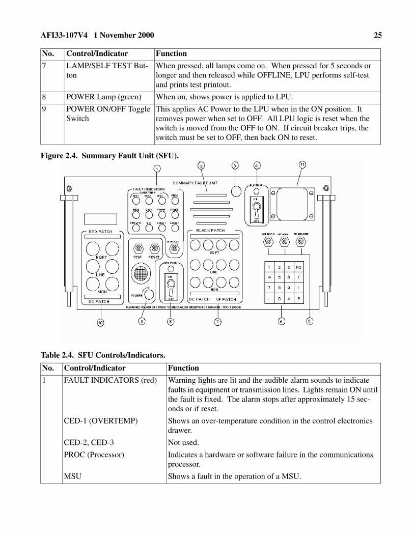
Figure 2.4. Summary Fault Unit (SFU). ....................................................................................... 25
Table 2.4. SFU Controls/Indicators. ........................................................................................... 25
Figure 2.5. Mass Storage Unit (MSU). ........................................................................................ 27
Table 2.5. MSU Controls/Indicators. .......................................................................................... 27
Figure 2.6. Control Electronics Drawer (CED-1). ....................................................................... 28

4 AFI33-107V4 1 November 2000
Table 2.6. Control Electronic Drawer (CED-1) Controls/Indicators. ......................................... 28
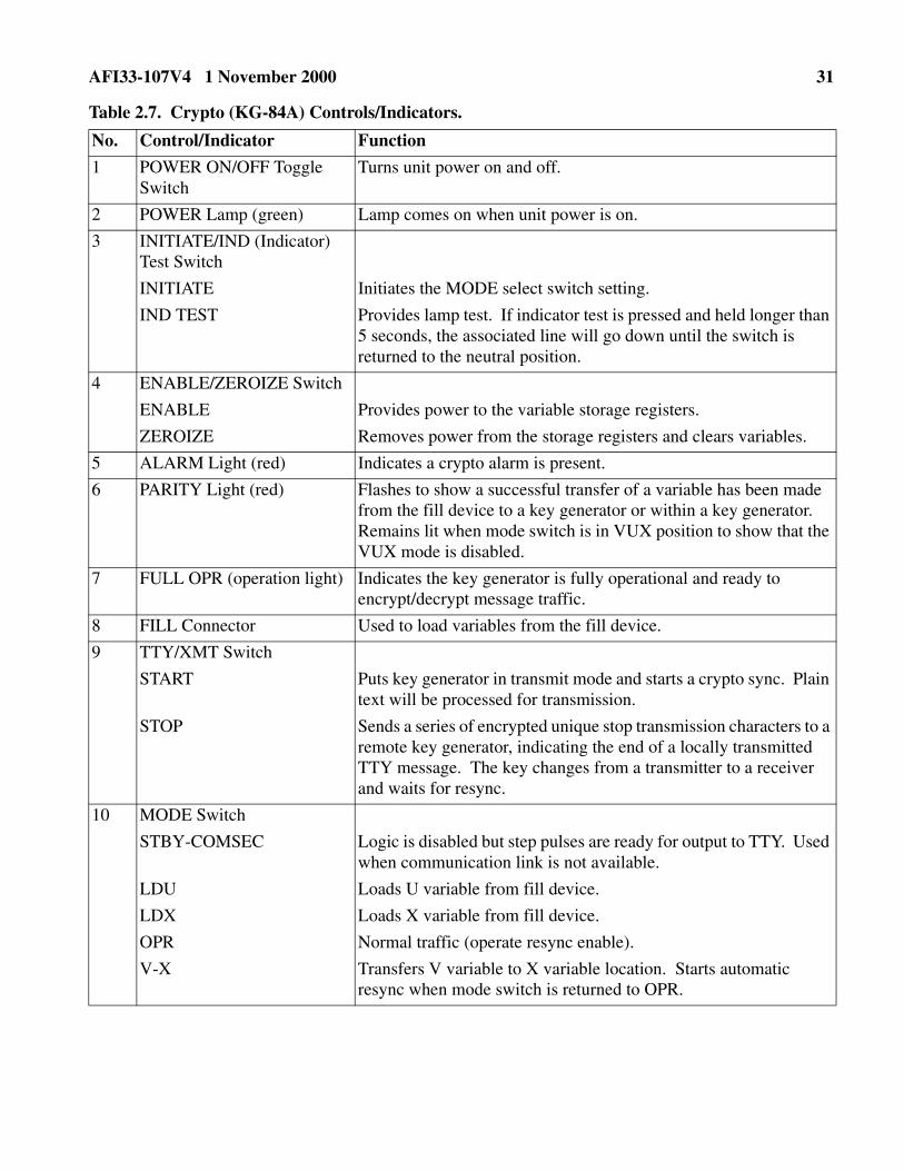
Figure 2.7. Crypto (KG-84A). ...................................................................................................... 30
Table 2.7. Crypto (KG-84A) Controls/Indicators. ...................................................................... 31
Figure 2.8. MODEM. ................................................................................................................... 32
Table 2.8. MODEM Controls/Indicators. ................................................................................... 32
Figure 2.9. Power Supply. ............................................................................................................ 34
Table 2.9. Power Supply Controls/Indicators. ............................................................................ 34
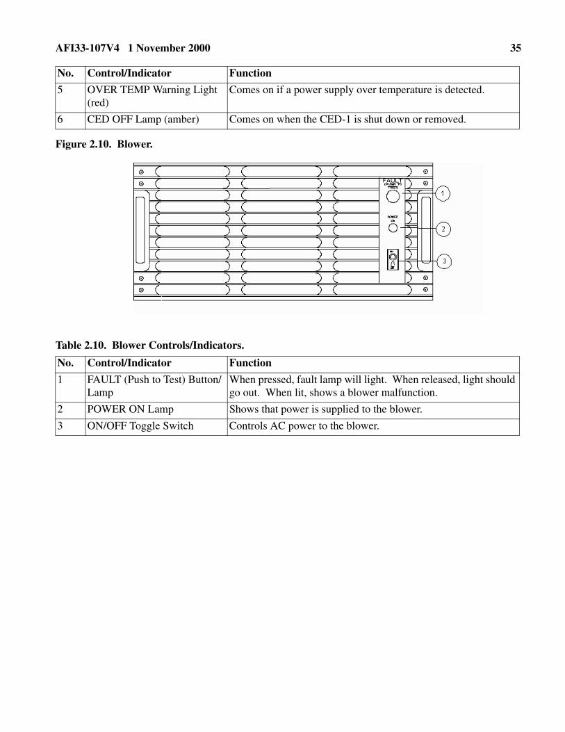
Figure 2.10. Blower. ....................................................................................................................... 35
Table 2.10. Blower Controls/Indicators. ....................................................................................... 35
Figure 2.11. Red Patch Panel. ........................................................................................................ 36
Table 2.11. Red Patch Panel Controls/Indicators. ........................................................................ 36
Figure 2.12. Black Patch Panel. .................................................................................................... 37
Table 2.12. Black Patch Panel Controls/Indicators. ..................................................................... 37
Chapter 3—AWCP/MUTE AND BCP FUNCTIONS 38
3.1. General. ...................................................................................................................... 38
3.2. Session Security Level. .............................................................................................. 38
3.3. Master and Preformat Menus. .................................................................................... 38
3.4. Header Composition Menu. ....................................................................................... 38
3.5. Free Form Message Composition. ............................................................................. 39
3.6. Text Composition. ..................................................................................................... 39
3.7. Master/Preformat Menu Storage/Modification/Deletion. .......................................... 39
3.8. AWCP/MUTE and BCP MSU 12 Storage Files. ...................................................... 39
3.9. Message Transmission. .............................................................................................. 40
3.10. VDU Screen Printing. ................................................................................................ 41
3.11. Display Message Queue. ............................................................................................ 41
3.12. Message Reception. ................................................................................................... 41
3.13. Message Retrieval. ..................................................................................................... 42
3.14. Message Delivery. ..................................................................................................... 44
3.15. Operator Tests. ........................................................................................................... 46
Table 3.1. Commands for Processor Functions. ......................................................................... 47
Figure 3.1. Session Security Level Menu. ................................................................................... 49

AFI33-107V4 1 November 2000 5
Figure 3.2. Master Menu. ............................................................................................................. 50
Figure 3.3. Preformat Menu. ........................................................................................................ 51
Figure 3.4. Header Composition Menu. ....................................................................................... 52
Chapter 4—AWCP/MUTE AND BCP OPERATOR COMMANDS AND PROCEDURES 53
4.1. General. ...................................................................................................................... 53
4.2. BCP Operator Station. ............................................................................................... 53
4.3. AWCP/MUTE Operator Station. ............................................................................... 53
4.4. Operational Commands. ............................................................................................ 53
4.5. AWCP/MUTE and BCP Power Up Procedures. ....................................................... 54
4.6. AWCP/MUTE and BCP Power Down Procedures. .................................................. 54
4.7. System Restarts and IPLs. ......................................................................................... 54
4.8. BCP Journal Diskette Replacement. .......................................................................... 57
4.9. BCP Stored Journal Message Retrieval. .................................................................... 59
4.10. Throttling. .................................................................................................................. 59
4.11. Status Table Printouts. ............................................................................................... 60
4.12. Copy Menu Diskettes. ................................................................................................ 60
4.13. Catalog Command/Auto Catalog. .............................................................................. 62
4.14. Catalog Format and Legal Values. ............................................................................ 63
4.15. Normal and Special BCP Catalog Procedures. .......................................................... 64
4.16. Catalog Problem Notice Outputs. .............................................................................. 65
4.17. Remote Data Transmission (RDT). ........................................................................... 67
4.18. Diskette Name Change for Journal Transmission. .................................................... 67
4.19. Systems Notification Messages. ................................................................................ 67
Figure 4.1. Line Status. ................................................................................................................ 67
Table 4.1. Line Status Printout. .................................................................................................. 68
Figure 4.2. Equipment Status. ...................................................................................................... 69
Table 4.2. Equipment Status Report. .......................................................................................... 69
Chapter 5—SACCS DESKTOP-TERMINAL 71
5.1. General. ...................................................................................................................... 71
5.2. SDT Capabilities. ....................................................................................................... 71
5.3. SDT Components. ...................................................................................................... 71

6 AFI33-107V4 1 November 2000
5.4. SACCS Transmit Program. ........................................................................................ 71
5.5. SDT Communications Program. ................................................................................ 72
5.6. SACCS Network Configuration. ............................................................................... 72
Figure 5.1. SDT Message Transmission Flow Diagram. ............................................................. 73
Figure 5.2. SDT Message Reception Flow Diagram. .................................................................. 74
5.7. Activity Log. ............................................................................................................. 74
Table 5.1. Activity Log Entries. .................................................................................................. 75
5.8. Error Notices and Corrective Actions. ....................................................................... 75
Table 5.2. Error notices generated by the Windows Operating System. .................................... 76
Table 5.3. Error Notices Generated by the SDT Communications Program. ............................. 76
5.9. Diagnostic Procedures. .............................................................................................. 77
5.10. System Outage Reporting Procedures. ...................................................................... 77
5.11. Maintenance Procedures. ........................................................................................... 77
5.12. Software Update Procedures. ..................................................................................... 77
Chapter 6—SYSTEM OUTAGE REPORTING PROCEDURES 78
6.1. General. ...................................................................................................................... 78
6.2. SACCS NQCC Responsibility. ................................................................................. 78
6.3. Procedures for Reporting PEP/SDT Outages. ........................................................... 78
6.4. Information Collections, Forms, and Records. .......................................................... 78
Attachment 1—GLOSSARY OF REFERENCES, ABBREVIATIONS, ACRONYMS, AND TERMS 80
Attachment 2—KEYBOARD REJECT AND WARNING MESSAGES 83
Attachment 3—LPU PAPER CHANGE PROCEDURE 85
Attachment 4—ESTABLISH SESSION SECURITY LEVEL 86
Attachment 5—MASTER/PREFORMAT MENU ACCESS 87
Attachment 6—HEADER COMPOSITION MENU 89
Attachment 7—HEADER COMPOSITION MENU ERROR CONDITIONS 91
Attachment 8—FREE FORM MESSAGE COMPOSITION 92

AFI33-107V4 1 November 2000 7
Attachment 9—MASTER/PREFORMAT MENU MESSAGE STORAGE/ MODIFICATION/DELETION 94
Attachment 10—MASTER/PREFORMAT MENU MESSAGE ERROR CONDITIONS 97
Attachment 11—MSU STORAGE FILE MESSAGE STORAGE/RETRIEVAL/ MODIFICATION/DELETION 98
Attachment 12—MSU STORAGE FILE MESSAGE ERROR CONDITIONS 101
Attachment 13—MESSAGE TRANSMISSION 103
Attachment 14—MESSAGE TRANSMISSION ERROR CONDITIONS 104
Attachment 15—PRINTING VDU SCREEN CONTENTS 106
Attachment 16—DISPLAY MESSAGES (REQUIRES DEPRESSING "DSPL MSG" KEY) 107
Attachment 17—MESSAGE RECEPTION 109
Attachment 18—MESSAGE RECEPTION ERROR CONDITIONS 111
Attachment 19—MESSAGE RETRIEVAL 112
Attachment 20—OPERATOR COMMANDS (USING A CUTE) 114
Attachment 21—SYSTEM NOTIFICATION MESSAGES 124
Attachment 22—ELECTRONIC PROGRAM UPDATE (EPU) PROCEDURES 128
Attachment 23—REMOTE DATA-TRANSMISSION (RDT) PROCEDURES 130
Attachment 24—DISKETTE NAME CHANGE FOR JOURNAL TRANSMISSION 134
Attachment 25—BCP/FA POWER UP/DOWN PROCEDURES 138
Attachment 26—AWCP/HFSSB POWER UP/DOWN PROCEDURES 141

8 AFI33-107V4 1 November 2000
Chapter 1
DATA TRANSMISSION SUBSYSTEM (DTS)
1.1. System Description.
1.1.1. The SACCS-DTS provides HQ ACC, HQ AMC, HQ USSTRATCOM, HQ AFSPC, and theNumbered Air Force commanders with operational information on strategic forces. It consists of twosubsystems: data transmission and data processing. Both subsystems are electronically automatedand interconnected to permit introduction of information at all levels to include the Missile LaunchControl Centers and to present summarized data to headquarters command posts without intermediatehuman handling. Under computer program control, the DTS network links all SACCS-DTS terminalunits, Automatic Digital Network (AUTODIN), and Defense Message Switching Transition Hub(DTH). It routes input information to the Command Control Processor Display Subsystem(CCPDS-R) and Data Processing Subsystem where it is summarized and prepared for presentationthrough the DTS to the command centers. The SACCS-DTS operates 24 hours per day and serves asthe primary operational data and record communications system within HQ ACC, HQ USSTRAT-COM, and HQ AMC. Additional reporting procedures can be found in Chapter 6.
1.1.2. The BCP has three equipment racks, a KSR-43 teletypewriter Switch Operator (SWOP) Sta-tion, and two Collocated User Terminal Elements (CUTE). The CUTE consists of the Visual DisplayUnit (VDU)/Keyboard (KB) and the Line Printer Unit (LPU).
1.1.3. The AWCP has one equipment rack and two CUTEs.
1.1.4. The HFSSB has one equipment rack and one CUTE.
1.1.5. The MUTE has one equipment rack consisting of a VDU/KB and LPU. The MUTE is HardUser Terminal Equipment (HUTE) with an external blower installed.
1.1.6. Many other communication processors may interface with the BCP. For example, severalAWCPs, MUTEs, Missile BCPs, and Subnet Communications Processors (SCP) will be connected tothe BCP. All of these subscribers depend on their SCP or BCP to maintain connectivity within theDTS network.
1.1.7. The AWCP/MUTE/HFSSB interfaces to a BCP located at another command post or to a SCPlocated at Offutt or Barksdale AFBs. The BCP or SCP is the accountable processor for messagestransmitted by any of the subscribers. When the AWCP/MUTE/HFSSB is nonoperational, messagesare being journaled at the accountable processor for delivery by the SWOP operator or the AWCP/MUTE/HFSSB operator when the AWCP/MUTE/HFSSB becomes operational. Accountable proces-sors are responsible for delivering all messages that have entered their system but have not been suc-cessfully delivered to the addressee or another accountable processor.
1.1.8. The DTS allows for the composition, transmission, receipt, and retrieval of messages. Thesemessages are packetized prior to being transmitted. Each packet may have up to a maximum of 256characters and long messages may consist of many packets. Each message is limited to 51 lines/80characters per line or 4,080 characters per message. Transmitted messages are sent to the parentaccountable BCP or SCP. The BCP/SCP journals the message and notifies the sender that the BCP/SCP has assumed responsibility for delivery of the message by sending a comeback copy of the mes-sage with the message identification (ID) (message number and date-time-group [DTG]) added. TheBCP/SCP then sends the message to its addressees by sending the message to the BCPs and SCPs
AFI33-107V4 1 November 2000 9
responsible for the destination. In turn, these BCPs/SCPs acknowledge receipt for the message andsend it to the destination for output at the VDU/LPU.
1.1.9. The DTS also provides for alternate routing if the primary addressee is down, initiates throt-tling to clear congested communication lines. In addition, the DTS provides for retrieval of previ-ously transmitted messages and those being held by an accountable processor because they wereundelivered for equipment failure. A received notice is displayed on the VDU, line 22, for messagesthat are actually transmitted.
1.2. SACCS Network Quality Control Center (NQCC).
1.2.1. The SACCS NQCC and the Support Section are located at the 55th Computer Systems Squad-ron at Offutt AFB NE. They have the responsibility of maintaining the integrity of the SACCS-DTSnetwork by monitoring the entire network and taking decisive action to quickly resolve outages whenthey occur. They are the final authority on decisions affecting the network.
1.2.2. SACCS NQCC personnel are responsible for reporting network availability to various officesin HQ USSTRATCOM and the 55th Communications Group to include Commander-in-Chief Strate-gic Command (CINCSTRATCOM) and the 55th Communications Group Commander.
1.2.3. To perform this function effectively, the SACCS NQCC must have accurate and timely inputsfrom SACCS sites regarding scheduled and unscheduled outages. The SACCS NQCC upchannels toHQ AFSPC/SCMB (SACCS lead command) all outages in excess of 36 hours when insufficient infor-mation is given by the site. HQ AFSPC/SCMB investigates these instances and provides feedback tothe SACCS NQCC and site management.
1.2.4. Frequently, the NQCC or support section directs network sites to send them printouts, journalor dump diskettes, and other needed information. When directed to do this, the site must send theneeded information to them as soon as possible. This information is needed to troubleshoot andresolve network problems.
1.2.5. If a network site has a problem or question, contact the SACCS NQCC or the Support Section.

10 AFI33-107V4 1 November 2000
Chapter 2
HARDWARE DESCRIPTIONS
2.1. General. This chapter describes each piece of equipment in the BCP and the AWCP/MUTE. Nor-mal operations, error conditions, and corrective actions are provided.
2.2. Visual Display Unit (VDU).
2.2.1. The VDU provides a visual picture of the user's keystrokes made on the VDU associated KB.In addition, events, notifications, and the status of the AWCP/MUTE or BCP is displayed. Table 2.1.provides a layout of the controls and indicators for the VDU.
2.2.2. Figure 2.1. shows the 24-line VDU display area consisting of: 19 lines for message composi-tion and editing, a separator line of dashes, 3 lines for notifications, and a VDU/KB status notificationline.
2.2.2.1. Lines 1-19, Message Composition Area. The VDU has a message composition area con-sisting of 52 lines/80 characters per line of which only the first 51 lines are usable for messagetransmission. This is the maximum size message that may be composed on the VDU/KB. Theuser may view any 19 lines of the 52-line message at any one time. The "LINE (arrow up)" and"LINE (arrow down)" keys are used to scroll messages on the VDU that are greater than 19 lines.If the cursor is scrolled off the screen, it can be returned to the upper left corner of the VDU bydepressing the "HOME" key.
2.2.2.2. Line 20, Separator Line. A line of dashes separates the display area into two parts: lines1-19 controlled by the user; lines 21-24 consisting of a session line, status message line, responseline, and VDU/KB status line controlled by the computer and the VDU/KB software.
2.2.2.3. Line 21, Session Line. This line provides the following information:
2.2.2.3.1. The number of messages stored in the display message queue and the precedence ofthe highest priority message in the queue (e.g., 02 Z).
2.2.2.3.2. The session security level established for message compositions.
2.2.2.4. Line 22, Status Message Line. This line is used by the computer to display events,notices, and the AWCP/MUTE or BCP status. The line 22 notice remains on the screen until the"OPR ACK" key is pressed to blank out the current notice and allow the next notice (if any) to beshown. The processor can only hold a limited number of notices between the two CUTEs, and ifnot acknowledged when received, some may be lost. The "OPR ACK" key lights up whenever anew notice is sent to the VDU/KB from the computer.
2.2.2.5. Line 23, Response Line. This line is divided into two parts and shows the systemresponses when one of the eight control keys is pressed. The left part shows the key pressed andthe right part shows the system response. The system response may be a message describing anerroneous user input.
2.2.2.6. Line 24, VDU/KB Line. Line 24 consists of 7 fields.
2.2.2.6.1. SCROLL LOCATION shows the first and last numbers of the 19 lines of the 52 linemessage composition area displayed on the VDU screen.

AFI33-107V4 1 November 2000 11
2.2.2.6.2. CURSOR POSITION shows a number indicating at what 80 column location thecursor is.
2.2.2.6.3. TEST shows one of the three test modes selected and is currently being tested.
2.2.2.6.4. TERMINAL STATUS indicates the status of the message composition area. Thethree status responses are "READY," "WAIT," and "BUSY."
2.2.2.6.5. KB RESPONSE indicates a keyboard entry was rejected and the reason why it wasrejected. This field also provides specific warnings. Attachment 2 lists the keyboard warn-ings and rejections.
2.2.2.6.6. I/O STATUS specifies the condition of the link between the VDU/KB and the com-puter. A blank in this field indicates a normal connection. "I/O OUT" indicates the computerlink has been lost.
2.2.2.6.7. VDU/KB FAILURE indicates a background diagnostics or self-test for the VDU orKB has failed and is followed by a visual fail indicator alarm being lit. The fail indicator alarmshows the VDU has failed a built-in check. The KB failure (KEY ERR) indicates a parityerror exists between the KB and the VDU. It shows up as a blob (bright square).
2.3. Keyboard (KB).
2.3.1. The KB is used to enter and manipulate data into the message composition buffer and toinstruct the computer to perform certain actions (e.g., transmit the message, clear the screen, displaymenus, etc.). The KB also provides the visual and audible alarm signals.
2.3.2. The KB has 12 different key groupings. Figure 2.2. shows, and Table 2.2. describes the KBand the purpose for each key. At times, KB entries are rejected or warning messages are displayed.The rejections and warnings may be accompanied by an audible "beep."
2.4. Line Printer Unit (LPU).
2.4.1. The LPU in Figure 2.3. provides a record copy of messages transmitted or received and systemnotification messages. The print function prints the contents of the display message buffer. The topand bottom of each page has a security banner. The security banner shows the security level (classifi-cation and category) of the message or the session security level if the "PRNT" key was pressed.Table 2.3. describes the controls/indicators and functions.
2.4.2. The error (blob or battery symbol) character indicates the LPU has received a value that is notwithin its printable character set. This is normally a control character. In some instances, it is used tohighlight an operator input error.
2.4.3. When the red stripe first appears on the right-hand side of the LPU paper, it indicates there areabout 25 pages remaining on the LPU roll of paper. The PAPER ALARM red lamp is illuminatedwhen no paper is available. When the PAPER ALARM light comes on, a notice is sent to the com-puter to stop sending messages to that LPU. The PRNT indicator lamp on the Summary Fault Unit(SFU) will remain on until the paper is changed. Replace the paper using the procedure in Attach-ment 3.
2.5. Summary Fault Unit (SFU).
12 AFI33-107V4 1 November 2000
2.5.1. The SFU provides warning lights and audible alarms that indicate there are failures in theequipment or irregularities in the transmission lines. Figure 2.4. shows, and Table 2.4. describes thefunction of each SFU control and indicator.
2.5.2. The SFU has four segments: transmission, line restoral, fault indicators, and power.
2.5.2.1. Transmission Segment. The RED and BLACK patch fields on the SFU are used by main-tenance personnel to reconfigure communication lines to bypass or troubleshoot equipment fail-ures at the AWCP/MUTE and BCP.
2.5.2.2. Line Restoral Segment. The Tone Dialing Unit (TDU), ON/OFF Hook buttons, TOMODEM button, key pad, and audio monitor are not used at the AWCP/MUTE and BCP.
2.5.2.3. Fault Indicator Segment. An audio alarm will alert the operator to an equipment mal-function. A lamp indicator will light, indicating the malfunction category (e.g., COMM1, PRINT,Mass Storage Unit [MSU], etc.). Each equipment drawer, except the MSUs, has its own faultlamp indicators to show which piece of equipment is bad. SFU visual and audible alarm signalsare as follows:
2.5.2.3.1. Visual Alarm Signals. Active fault lamps are lit red when a fault happens. Theselamps remain on until the fault is cleared. Disconnected or unused communications lines causeCOMM1 and COMM2 lights to illuminate. They can be reset (turned off) by entering thecommand "SFU." Any subsequent failure of operational equipment causes the light to indi-cate a failure.
2.5.2.3.2. Audible Alarm Signals. An audible alarm sounds whenever a fault lamp indicatoris lit. The alarm automatically shuts off after 15 seconds; however, the fault lamp indicatorremains on until the fault is cleared. Manually shut off the alarm by pressing the RESET but-ton on the SFU panel.
2.5.2.4. Power Segment. Red and black DC power is supplied to the SFU from the Power SupplyDrawer. SFU RED and BLACK PWR toggle switches provide the power when in the "ON" posi-tion.
2.6. AWCP/MUTE Mass Storage Unit (MSU).
2.6.1. The MSU is a flexible disk drive that provides on-line storage on changeable floppy diskettes.These diskettes provide the computer software and files needed to operate the AWCP/MUTE. Thereare two MSU drives at the AWCP/MUTE. Figure 2.5. shows, and Table 2.5. describes the MSU con-trols and indicators.
2.6.2. Each MSU is assigned a specific function at the AWCP/MUTE. The diagram below shows thefloppy diskette assignments on the MSUs.
CAUTION! Keep fingers and foreign objects out of the patch fields!
MSU 12MENUS and EPU Files
MSU 02IPL and DUMP FILES

AFI33-107V4 1 November 2000 13
2.6.2.1. MSU 02 (PRI) is the preferred location for the Initial Program Load (IPL) diskette. TheIPL diskette is the source of the computer instructions needed to operate the AWCP/MUTE. Thecomputer program is read from the IPL diskette into the computer's main memory at IPL. Oncethe IPL is completed, a prompt to mount a DUMPFILE diskette is received. Replace the IPL dis-kette with a DUMPFILE diskette and respond to the prompts. If the AWCP/MUTE performs anauto restart or the operator performs a manual restart, a dump of the computer's memory is madeto the DUMPFILE diskette. This DUMPFILE diskette must be replaced with another DUMP-FILE diskette in accordance with the LPU operator station prompts received. The removedDUMPFILE information must then be made available to programmers for subsequent analysisand resolution of a problem. Basic information about each restart is automatically provided to theSACCS NQCC operator for evaluation by program managers. Retain each restart DUMPFILEdiskette for a minimum of 10 days unless told otherwise by the SACCS NQCC.
2.6.2.2. MSU 12 is the normal device for the MENU diskette that contains the master, preformat,MSU, and Electronic Program Update (EPU) files. This diskette is used to store messages (e.g.,ASORTIE, FLTFL, OPREP-3s, etc.). Both CUTEs share the same master and preformattedmenus. Each CUTE is assigned 80 separate MSU storage files; however, CUTE #1 cannot accessCUTE #2's MSU storage files and vice versa. There are 216 locations to store messages. While216 entries are available to store messages, not all may be available. Each segment of recordingspace requires one of the entry numbers and if the file to be stored is larger than an available entry,it will be rejected. If the file to be entered is smaller than an entry location, it will be stored but thespace left over will also use an entry number. It is, therefore, prudent to delete files that are notneeded or used often. This menu diskette may be removed and replaced using the Catalog com-mand. MSU 12 also serves as a back-up IPL and DUMPFILES MSU drive in the event MSU 02fails. If AWCP/MUTE MSU 12 is used as the IPL drive and MSU 02 is inoperative, menus canstill be made available. When the prompt to enter the DTG is output, replace the IPL diskette withthe menu diskette. Enter the DTG prompt and when the dump mount is requested, respond "#NO." This is a degraded mode of operation and should not normally be used.
2.6.2.3. EPU IPL. An EPU IPL is only performed when new software has been electronically dis-tributed to the BCP or AWCP/MUTE. An EPU IPL accomplishes the same thing as a cold IPL. Italso performs the additional task of combining software that has been received and transferred toa file on the menu diskette with that existing on the installed IPL diskette. An EPU IPL does notsave the current journal, so it must be removed and replaced as part of the IPL process. This canbe done with the long-term journal (LTJ) closure command just before the EPU IPL.
2.7. BCP Mass Storage Unit (MSU).
2.7.1. The MSU is a flexible disk drive that provides on-line storage on changeable floppy diskettes.These diskettes provide the computer software and files needed to operate the BCP. There are sixMSU drives at the BCP. Figure 2.5. describes the MSU controls and indicators.
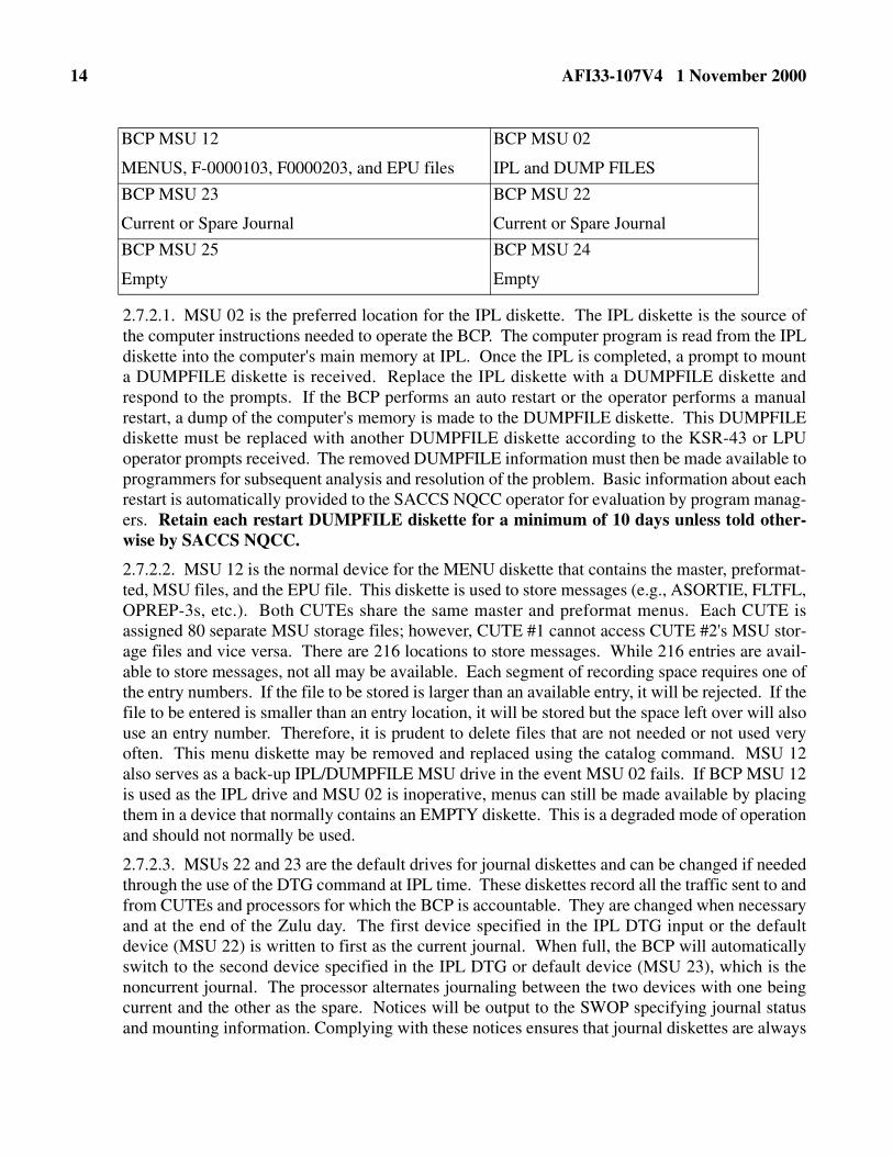
2.7.2. Each MSU is assigned a specific function at the BCP. The diagram below shows the floppy dis-kette assignments on the MSUs.
14 AFI33-107V4 1 November 2000
2.7.2.1. MSU 02 is the preferred location for the IPL diskette. The IPL diskette is the source ofthe computer instructions needed to operate the BCP. The computer program is read from the IPLdiskette into the computer's main memory at IPL. Once the IPL is completed, a prompt to mounta DUMPFILE diskette is received. Replace the IPL diskette with a DUMPFILE diskette andrespond to the prompts. If the BCP performs an auto restart or the operator performs a manualrestart, a dump of the computer's memory is made to the DUMPFILE diskette. This DUMPFILEdiskette must be replaced with another DUMPFILE diskette according to the KSR-43 or LPUoperator prompts received. The removed DUMPFILE information must then be made available toprogrammers for subsequent analysis and resolution of the problem. Basic information about eachrestart is automatically provided to the SACCS NQCC operator for evaluation by program manag-ers. Retain each restart DUMPFILE diskette for a minimum of 10 days unless told other-wise by SACCS NQCC.
2.7.2.2. MSU 12 is the normal device for the MENU diskette that contains the master, preformat-ted, MSU files, and the EPU file. This diskette is used to store messages (e.g., ASORTIE, FLTFL,OPREP-3s, etc.). Both CUTEs share the same master and preformat menus. Each CUTE isassigned 80 separate MSU storage files; however, CUTE #1 cannot access CUTE #2's MSU stor-age files and vice versa. There are 216 locations to store messages. While 216 entries are avail-able to store messages, not all may be available. Each segment of recording space requires one ofthe entry numbers. If the file to be stored is larger than an available entry, it will be rejected. If thefile to be entered is smaller than an entry location, it will be stored but the space left over will alsouse an entry number. Therefore, it is prudent to delete files that are not needed or not used veryoften. This menu diskette may be removed and replaced using the catalog command. MSU 12also serves as a back-up IPL/DUMPFILE MSU drive in the event MSU 02 fails. If BCP MSU 12is used as the IPL drive and MSU 02 is inoperative, menus can still be made available by placingthem in a device that normally contains an EMPTY diskette. This is a degraded mode of operationand should not normally be used.
2.7.2.3. MSUs 22 and 23 are the default drives for journal diskettes and can be changed if neededthrough the use of the DTG command at IPL time. These diskettes record all the traffic sent to andfrom CUTEs and processors for which the BCP is accountable. They are changed when necessaryand at the end of the Zulu day. The first device specified in the IPL DTG input or the defaultdevice (MSU 22) is written to first as the current journal. When full, the BCP will automaticallyswitch to the second device specified in the IPL DTG or default device (MSU 23), which is thenoncurrent journal. The processor alternates journaling between the two devices with one beingcurrent and the other as the spare. Notices will be output to the SWOP specifying journal statusand mounting information. Complying with these notices ensures that journal diskettes are always
BCP MSU 12
MENUS, F-0000103, F0000203, and EPU files
BCP MSU 02
IPL and DUMP FILES
BCP MSU 23
Current or Spare Journal
BCP MSU 22
Current or Spare Journal
BCP MSU 25
Empty
BCP MSU 24
Empty

AFI33-107V4 1 November 2000 15
available to the processor. The BCP cannot run without a journal and a symptom of no journalsresults in no processor input, output, or responses. It is important to keep track of which is the cur-rent and spare journal devices. This information is needed to perform warm IPLs. Make twosmall cardboard signs with the words "CURRENT" and "SPARE" printed on them for mountingon the MSU doors. Swap the two signs as the journals are changed to keep track of the current andspare journals. The on-line journals (current and spare) must not be confused with noncurrentjournals that are journals that have been recorded to and closed out by the processor. The noncur-rent journals are used for message retrievals if the message is not on the current journal. Noncur-rent journal information should be recorded on a log for future reference.
2.7.2.4. MSU 24 is a device that has no active files as such, but can be assigned to accomplishfunctions if required. The primary use is for message retrieval from noncurrent journals. It canalso be used as an alternate device for DUMPFILES or MENUS. This device is normally shownas EMPTY and is available for assignment if not in use.
2.7.2.5. MSU 25 is a device that has no active files as such, but can be assigned to accomplishfunctions if required. It can also be used as an alternate device for DUMPFILES or MENUS.This device is normally shown as EMPTY and is available for assignment if not in use.
2.8. Care of Diskettes.
2.8.1. Handling Diskettes. Each diskette has unique computer codes (language) and file structures onit to identify its purpose. Do not use any other kind of diskette (e.g., word processing) in the MSUs.Keep the diskettes clean and free from contamination. Do not use a diskette whose surface has beencontaminated by fluids, fingerprints, hair, dust, smoke particles, etc. If a contaminated disk is used inthe MSU, the MSU read/write heads can become contaminated and cause errors. The contaminantscan then be passed onto other clean diskettes. The following rules apply to diskette handling:
2.8.1.1. DO NOT touch or clean the exposed diskette surface.
2.8.1.2. DO NOT place objects on the diskette.
2.8.1.3. DO NOT fold or bend the diskettes.
2.8.1.4. DO NOT use paper clips, rubber bands or tape on the diskettes.
2.8.1.5. DO NOT expose the diskettes to excessive heat.
2.8.1.6. DO NOT eat, drink, or smoke while handling diskettes.
2.8.1.7. DO NOT use magnetized objects (including a telephone receiver) near the diskettes.
2.8.1.8. DO NOT make erasures on or near the diskette. Graphite particles from pencils cancause diskette contamination and destroy the MSU.
2.8.1.9. DO NOT use pencils to mark diskette labels. Use a felt tip pen to mark labels.
2.8.1.10. Return diskettes to their storage envelopes each time they are removed from the MSU.Store single diskettes in their original box with each diskette in its protective envelope.
2.8.2. Loading Diskette into the MSU. All diskettes must have a label on the top located in theright-hand corner. The label must be facing up as it is being loaded into the MSU.
2.8.3. Write Protect. MSU devices have a write protect feature for diskettes. All write-protect dis-kettes used in MSUs must have the write protect notch covered if the diskette has one. If a diskette is
16 AFI33-107V4 1 November 2000
detected with the 1/4 inch square write protect notch located to the left of the head read/write area(diskette marked with labels up and head read/write slot away from person inserting diskette) not cov-ered, the processor will be unable to write to the disk. Ensure that the write protect notch is coveredwith a write tab.
2.9. Control Electronics Drawer (CED-1).
2.9.1. CED-1 houses the computer and performs the central processing, memory storage area, andline control.
2.9.2. The computer software is read into the CED-1 from the IPL diskette during the IPL. All func-tions of the AWCP/MUTE and BCP are controlled by this operation.
2.9.3. The CED-1 controls and indicators are shown in Figure 2.6., and described in Table 2.6.
2.10. Crypto (KG-84A). The Crypto (KG-84A) provides communications security protection for everymessage transmitted on a dedicated communication line between any two connected DTS nodes. Themode switch for normal SACCS operation should be placed in the remote (RMT) position. Proceduresfor SACCS X Key Load/Change are described in the Operator's Guide. Crypto controls and indicators areshown in Figure 2.7., and described in Table 2.7.
NOTES:1. Operation of the Crypto (KG-84A) is classified Confidential and can be found in KAO-184,
Guidelines for the Use and Operation of the KG-84/84A. The KAO-184 is distributed throughCOMSEC accounts.
2. When a Crypto LAMP TEST is activated for longer than five seconds, the communication linewill automatically be brought down for the duration of the test. The appropriate lights on the SFUcome on and a "line down" notice prints at the LPU/SWOP station at both ends of the communi-cation line. In order to avoid confusion for the operator at the other end of the line, the operatormust advise the connecting nodes whenever an extended LAMP TEST (more than five seconds)is to be activated.
2.11. Modem. The modem performs the necessary modulation and demodulation on the signals transmit-ted and received over the DTS communication lines. Figure 2.8. shows and Table 2.8. describes modemcontrols and indicators for the SACCS modem MO-1140/FSC-83(V). The Data Communications Inter-face Units (DCIU) that replaced some SACCS modems does not have any user controls.
2.12. Power Supply. This unit supplies power for equipment not connected to an internal DC power sup-ply. The drawer is divided into two sections (red and black) to isolate power for the circuits handlingunencrypted classified data (red circuits) from those handling unclassified or encrypted data (black). Fig-ure 2.9. shows and Table 2.9. describes power supply controls and indicators.

AFI33-107V4 1 November 2000 17
2.13. Blower. The blower provides the cooling air for all of the equipment in the equipment racks. Theblower controls and indicators are shown in Figure 2.10. and described in Table 2.10.
2.14. Red DC Patch Module. The red DC patch module provides maintenance personnel with patchingand monitoring capabilities. The monitoring jacks, the TEST IN jacks, and the 32-jack TEST ACCESSfields are for maintenance use only. Figure 2.11. shows and Table 2.11. describes the red DC patch mod-ule controls and indicators.
2.15. Black DC Patch Module. The black DC patch module provides maintenance personnel withpatching and monitoring capabilities. The monitoring jacks, the TEST IN jacks, and the two 16 TESTACCESS fields are for maintenance use only. Figure 2.12. shows and Table 2.12. describes the black DCpatch module controls and indicators.
2.16. BCP Operator Station. The BCP KSR-43 teletypewriter, referred to as the operator station, isused as the primary device to control the communications processor and its functions. It controls the nodethrough entry of operator commands and provides status of the node and SACCS-DTS network via sys-tem notifications and prompts.
2.16.1. The BCP KSR-43 provides for node control through operator entry of various commands.These commands include the entries for IPL and commands for reconfiguration of the operating sys-tem. Status messages for equipment within the node and communication lines from the BCP to othernodes are printed at this position. Notices of undelivered messages, for which the BCP has acceptedresponsibility, will be printed at this position. Notices are also printed at this position to mount newfiles (e.g., DUMPFILES, journal diskettes, etc.) or diskettes having stored journal message files formessage retrieval requests.
2.16.2. Although the KSR-43 is the primary terminal used for switch operator commands, a printerVDU/KB can be assigned the functions of the switch operator station. Assigning the switch operatorfunctions to the printer VDU/KB does not override any capabilities of the existing printer VDU/KB.Instead, it adds the switch operator function to its capabilities.
2.16.3. The KSR-43 keyboard layout, control, and indicators are shown and described in the BCPoperator's guide. Paper replacement and ribbon replacement procedures are also described in the
WARNING!Normally, the circuit breakers are all kept in the ON position. If one or more of the circuit breaker switches is tripped (i.e., goes to the center position), follow the power down and power up sequences to prevent power surge damage to other equipment. If the circuit breaker continues to trip, call maintenance. Reference the Power Up and Power Down checklists in your Operator's Guide.
CAUTION! Keep foreign objects (pencils, fingers, etc.) out of the patch fields.
CAUTION! Keep foreign objects (pencils, fingers, etc.) out of the patch fields.

18 AFI33-107V4 1 November 2000
guide. For additional information, see the General Technical Reference for the Teletype Model 43ASP, KSR, and RO data terminals.
Figure 2.1. 24-Line VDU Display Area.
Table 2.1. VDU Controls/Indicators.
NOTE: MUTE uses different VDU but operates in a similar manner with like controls/indicators.
No. Control/Indicator Function
1 Visual Monitor Assembly (VMA) CB RESET/OFF
Removes AC power from VMA (display tube) portion of VDU when circuit breaker automatically trips on current overload. The circuit breaker must be placed to the RESET position to restore AC power to the VMA.
2 VMA TEST V Button Initiates self-test function of the VMA. Test pattern (left 1/3 black, right 2/3 bright [cursor] white) appears on BDU screen when pushed. No data is transmitted, lost, or altered when this button is pushed.
3 BRT INC Switch Adjusts brightness control on the VDU screen. Minimum set-ting does not extinguish the display.
4 VDU CB RESET/OFF Removes DC power from the VDU/KB. Do not reset circuit breaker if it continues to trip.
5 FAIL VDU/KU Lamp Indicates a VDU or KB operational fault.
6 DC PWR Lamp When illuminated, indicates loss of VDU DC logic power. AC power is still available.
7 POWER ON Lamp Indicates AC power is being supplied to VDU. VDU CB must be in the RESET position to activate this lamp.
8 POWER ON/OFF Toggle Switch When ON, applies AC power to the VDU/KB.

AFI33-107V4 1 November 2000 19
Figure 2.2. Keyboard (KB).

20 AFI33-107V4 1 November 2000
Table 2.2. KB Controls/Indicators.
No. Control/Indicator Function
1 CLR LVL (Clear Level) Pushbutton Switch
When pressed, clears the message composition buffer and VDU dis-play, and turns off all switch indicators on the keyboard. When released, active switch indicators come on and security menu is dis-played on VDU lines 1-19. Also permits reset of VDU/KB fail indica-tor.
2 MEM CLR (Memory Clear) Push-button Switch
When pressed, clears the message composition buffer and VDU dis-play. First 19 lines of message composition buffer are displayed on VDU, cursor appears at line 1 column 1, and VDU line 23 displays: MEM CLR ENTER MESSAGE.
3 SCRN CLR (Screen Clear) Push-button Switch
When pressed, clears the message composition buffer and VDU dis-play of all unprotected entries. The cursor homes (returns to VDU line 1, column 1, or the first unprotected position.) Any protected display (such as a message Preformatted or a header composition menu) previ-ously selected, continues to be displayed.
4 DSPL MSG (Display Message) Push-button Switch
When pressed, the current security level is terminated. The next mes-sage in the message queue (series of messages waiting to be displayed) is displayed on the VDU. The security level matches that of the mes-sage. All switch indicators on the VDU go off. (When push button is released, all active switch indicators come on.) VDU line 21 displays new security level and queue status. Key is locked (will not respond) if message queue is empty.
5 Editing Key These keys permit editing a message during message composition or before transmitting, for correcting or updating. Maximum length of a message is 52 (51 usable) lines. Maximum length of a line is 80 char-acters and spaces. Insertion of a line is not possible if message length is 52 lines. Insertion of a character is not possible if line length is the full 80 characters.
INS (Insert) LINE Key When pressed, moves cursored line down one line, and cursor moves to column 1 of new blank line. If 19 lines of the displayed portion of the 52 lines are full, the last line moves off the bottom of VDU display.
DEL (Delete) LINE Key When pressed, the line displaying the cursor is deleted. If a line below
the 19th line displayed on the VDU exists, it moves up to VDU line 19. Cursor remains in same position unless the character on the line mov-ing up is a protected character; in that case, the cursor moves forward to the next unprotected character on the same or a following line. (Pressing DEL LINE for a line with protected characters will not cause the line to be deleted. DEL CHAR key must be used.)

AFI33-107V4 1 November 2000 21
LINE (Up/Down) Keys These are the scrolling keys, for scrolling the VDU display up or down the message composition buffer contents. Any 19 of the 52 lines may be displayed in sequence as a group. The cursor moves as its line is scrolled, leaving the VDU display if the line scrolls off the display. Lines being displayed are shown on VDU line 24, columns 1-5. Press-ing the key one time moves the display one line. Holding the key down causes line-by-line movement to repeat until key is released. The 52-line display field cannot be scrolled completely off the VDU dis-play area in either direction.
INS (Insert) CHAR When pressed, characters to the right of the cursor move to the right by one column. (Cursor must be to right of protected characters.) Each time the key is pressed, a new blank appears at the cursor position until a character is in column 80.
DEL (Delete) CHAR When pressed, character at cursor position is deleted, and characters to the right of the cursor move left one column.
Cursor Positioning (Arrow Keys)
The up and down arrow keys cause the cursor to move straight up or down the VDU display, line by line, or to the next line having an unpro-tected character. When the cursor reaches the bottom of the VDU dis-play, the next key depressed moves it to the bottom (or top), and the cursor positioning can be continued.
The left and right arrow keys cause the cursor to move left or right to the next unprotected character. When the cursor reaches the end of its line, it continues up (or down) to the next line. When the end of the VDU display is reached, the cursor will jump to the other end of the VDU display and continue. Pressing the key once moves the cursor one position; holding the key down causes repetitive cursor movement.
6 SCRN BLNK (Screen Blank) Switch Indicator
Used to blank the VDU display temporarily without destroying it (to protect classified information from unauthorized personnel, and as a screensaver to prevent the menu from being burned into the face of the CRT.) When pressed, it comes on and VDU (all 24 lines) is blanked. When pressed again, it goes out and VDU display is restored.
7 XMT (Transmit) Switch Indicator
When pressed, it initiates the message transmission sequence. The XMT indicator comes on and the switch is locked and remains so until message either fails the pretransmission header checks or is accepted for transmission. Advice of failure is indicated on the VDU. Success-ful transmission is indicated by message printout on the LPU.
NOTE 1: No. 8 through 12 are dual function keys shown with their functions separated by a "/." The first of the two functions is selected by first pressing and holding the keyboard SHIFT key.
NOTE 2: The TO, INFO, ZEN, and N/M keys must be used if it is desired to establish the associated address field.
No. Control/Indicator Function

22 AFI33-107V4 1 November 2000
(Message Composing Keys)
8 ACK/TO Acknow-ledgment/To)
ACK - Not used.
TO - For defining TO addresses in a message header. Needs four posi-tions: (space) TO ( space). If positions are not available the entry is rejected.
9 NAK/INFO (Negative Acknowledgment/ Infor-mation)
NAK - Not used.
INFO - Used if INFO addresses are required in a message header. Needs 6 spaces: (space) INFO (space). If positions are not available, the entry rejected.
10 ETB/ZEN (End of Text Block/Special Non-DTS Message)
ETB - Not used.
ZEN - Used if ZEN (delivered by other means) addresses are required in a message header. Needs five spaces: (space) ZEN (space). If posi-tions are not available, the entry is rejected. It is used for information to recipients of message. The DTS does not take action on ZEN addressees.
11 N/M/SOH (Part N of an M Message/Start of Header)
N/M - Used in a free-form message header when required to indicate part (N) of total parts (M) of a message. Used at column 1 on line fol-lowing last address. N/M key is pressed, leaving a space at column 1. Then "part of parts" is keyed in the following example: PART (space) 01/02.
SOH - Optional key to indicate start of header symbol in free-form header composition. If used, it is the first symbol entered in the line containing the security classification. If not used, it is inserted auto-matically during header processing before message transmission.
12 L (boxed) STX (Protected Character/Start of Text)
L (boxed) - When pressed, causes space or character at cursor location to be protected. This character is displayed at reduced intensity and may not be edited or deleted without deleting the entire message.
STX - Causes the start of text symbol to be entered following the mes-sage header.
13 ETX (End of Text) Key Causes the End of Text symbol to be entered. The EXT must be entered at the end of a message or Preformatted in order for it to be stored in memory, printed from the screen, or transmitted.
14 SCRN (Screen) TEST Key
When pressed, the VDU screen displays a test pattern. When pressed again, VDU returns to current display status.
15 KEY TEST Key When pressed, VDU displays a matrix that permits testing of keyboard function keys. When pressed again, VDU display returns to normal, but the message composition buffer must be cleared before proceeding.
No. Control/Indicator Function

AFI33-107V4 1 November 2000 23
16 LAMP TEST Key When pressed, keyboard and VDU indicators and keyboard audio tone are tested. When pressed again, displays return to normal and audio keyboard beep tone is tested.
17 MSU (Mass Storage Unit) Key
When pressed, the contents of the message composition buffer are stored on the MSU file.
18 FORMAT Key When pressed, a message in the message composition buffer is stored in memory and the format menu is displayed so that the operator can list the message on the Master or Preformat Menus.
19 PRNT (Print) Key When pressed, the contents of the message composition buffer are printed on the LPU.
20 ENTER Key Used to initiate selections on menus and to initiate operator commands.
21 MENU Key Used to call up the Master Menu.
22 EAM, ACK (Emergency Action Message Acknowledge-ment) EAM Switch Indicator
Flashes (and keyboard audio tone sounds) when EAM is received. Goes off when pressed. If pressed within 80 seconds of initial message receipt, it initiates an EAM acknowledgment to the originator and stores the message in comparison queue. It is locked when the indica-tor is off.
23 RETURN Key When pressed, advances cursor to first unprotected position on next line. If the next line is below the VDU display, the display scrolls up a line automatically.
24 RPT (Repeat) Key For most keys, when pressed and held, causes a key (shifted or unshifted) to repeat when pressed. Repeat continues as long as RPT key is held down, even if the selected key released.
25 TAB (right, left) Key Cursor positioning key. Without SHIFT key, moves cursor right to the next unprotected position, continuing down to next line(s) as required. At end of VDU line 19, proceeds to line 1 and continues. With SHIFT key, moves cursor left and up the VDU display.
26 SHIFT Keys Used to select upper character in dual-purpose keys. (Example: +/2 without shift produces 2; with shift, produced +.)
27 HOME Key When pressed, moves the cursor to the first unprotected position on the VDU display. Use to retrieve the cursor if it was scrolled off the VDU display.
28 OPR ACK (Operator Acknowledge) Switch Indicator
Comes on when an operator advisory appears on VDU line 22. Indica-tor goes off when pressed if there are no other operator advisories in the queue. If keyboard audio tone accompanies indicator, silences audio tone when pressed. (Keyboard audio tone sounds when an EAM is received.) Locked when indicator is off.
29 DC4/US, DC3/RS, thru DC2/GS, DC1/FS Keys 32
Used during keyboard test only.
No. Control/Indicator Function

24 AFI33-107V4 1 November 2000
Figure 2.3. Line Printer Unit (LPU).
Table 2.3. Line Printer Unit Controls/Indicators.
30 CLR (Clear) TAB SET Key
Used to set tabs at one or more of the 80 columns of the VDU display, or to clear a previously set TAB. The clear tab operation requires pressing and holding the SHIFT key, then pressing the CLR TAB SET key. The set tab operation requires pressing the CLR TAB SET key without using the SHIFT key. The cursor selects the column where tab clear or set is required.
31 Typewriter Keyboard Character and function typing keys.
32 Annunciator Loudness Control
Controls loudness of keyboard audio tone and beep. (Maintenance adjustment.)
No. Control/Indicator Function
1 ON LINE/OFF LINE Button manually enables or disables LPU.
2 ON LINE Segment Indicates LPU is ready.
3 OFF LINE Segment (white or red)
White shows that LPU has been manually switched to OFF LINE or has not been manually switched to ON LINE after power up. Red shows that LPU has been automatically switched to OFF LINE state, and LPU is not operating due to a malfunction or out of paper condi-tion.
4 PAPER ALARM Warning When on, paper supply is exhausted or paper is torn or jammed. Goes out when condition is fixed.
5 FORM FEED Button When pressed, paper advances to the top of the next page.
6 INITIALIZE Button When pressed, all LPU logic is reset. Any stored data waiting to be printed is erased.
No. Control/Indicator Function
AFI33-107V4 1 November 2000 25
Figure 2.4. Summary Fault Unit (SFU).
Table 2.4. SFU Controls/Indicators.
7 LAMP/SELF TEST But-ton
When pressed, all lamps come on. When pressed for 5 seconds or longer and then released while OFFLINE, LPU performs self-test and prints test printout.
8 POWER Lamp (green) When on, shows power is applied to LPU.
9 POWER ON/OFF Toggle Switch
This applies AC Power to the LPU when in the ON position. It removes power when set to OFF. All LPU logic is reset when the switch is moved from the OFF to ON. If circuit breaker trips, the switch must be set to OFF, then back ON to reset.
No. Control/Indicator Function
1 FAULT INDICATORS (red) Warning lights are lit and the audible alarm sounds to indicate faults in equipment or transmission lines. Lights remain ON until the fault is fixed. The alarm stops after approximately 15 sec-onds or if reset.
CED-1 (OVERTEMP) Shows an over-temperature condition in the control electronics drawer.
CED-2, CED-3 Not used.
PROC (Processor) Indicates a hardware or software failure in the communications processor.
MSU Shows a fault in the operation of a MSU.
No. Control/Indicator Function

26 AFI33-107V4 1 November 2000
DISK Not used.
VDU/KB Shows a fault in VDU or KB operations.
PRINT Shows a fault in LPU operation, including torn paper, paper jam, or no paper supply.
PWR SUPPLY Shows a fault in the power supply drawer.
BLO (Blower) Shows a fault in the blower unit.
COMM 1 (Communication Line 1)
Shows a fault in the key generator (KG-84) operation, and/or that SLFCS and/or AFSAT line is down, or if accompanied by COMM 2 fault light, a degraded communication line.
COMM 2 (Communication Line 2)
Shows a fault in Modem operation, and/or that SLFCS and/or AFSAT line is down, or if accompanied by a COMM 1 light, a degraded communication line.
LAMP TEST Button When pressed, all FAULT INDICATOR warnings come on. When released, all except active INDICATOR warning lights go out.
2 LOUDSPEAKER Not used.
3 AUDIO VOLUME Control Not used.
4a BLK (Black) PWR Lamp (green)
Comes on when the power supply drawer is supplying DC power to the Summary Fault Unit black circuitry.
4b BLK PWR ON/OFF Toggle Switch
Controls DC power to the Summary Fault Unit black circuits.
5 OH HOOK Button/Light Not used.
OFF HOOK Button/Light Not Used.
TO MODEM Button/Light Not Used.
6 TDU Not used.
7 BLACK PATCH Jacks Used by maintenance personnel.
8 RED PWR Lamp (green) Lamp comes on when the power supply drawer is providing DC power to Summary Fault Unit red circuitry.
ON/OFF Toggle Switch This controls DC power to the Summary Fault Unit red circuit.
9 ALARM
AUDIO Alarm Sounds when the FAULT INDICATOR warning lights come on. The alarm stops after 15 second or if reset.
VOLUME Control Adjusts loudness of alarm, but does not shut it off.
TEST Button Used to test alarm. Alarm sounds as long as button is pushed.
RESET Button Shuts off the alarm before its 15 second time-out, if pressed.
10 RED PATCH Used by maintenance personnel.
No. Control/Indicator Function

AFI33-107V4 1 November 2000 27
Figure 2.5. Mass Storage Unit (MSU).
Table 2.5. MSU Controls/Indicators.
11 RACK AC POWER ON/OFF Switch Circuit Breaker
AC POWER ON/OFF toggle switch/circuit breaker. Permits operator to connect and disconnect primary AC power to the cab-inet.
Indicator Indicates that AC power is applied and circuit breaker is closed when lamp is on.
NOTE: At AWCPs and HFSSBs, the cover is removed and switch/circuit breaker is used to apply and disconnect AC power. The MUTE uses a different SFU but operates in a similar manner with like con-trols and indicators.
CAUTION! MSU doors must be opened only to change diskettes. Opening the doors takes the MSU off line and exposes the diskette and MSU to dust and other contamination.
No. Control/Indicator Function
1 Door and Door Knob Provides access to the file diskette. While door is open, MSU is off line and the MSU fault lamp on the SFU will come on when the CED-1 detects the condition.
2 RDY (Ready) Light (green)
Shows diskette is loaded correctly and the disk drive is ready to perform read or write operations.
3 POWER Lamp (green) Comes on when power is applied to MSU.
4 POWER OFF/ON Tog-gle Switch
Controls AC power to the MSU.
No. Control/Indicator Function

28 AFI33-107V4 1 November 2000
Figure 2.6. Control Electronics Drawer (CED-1).
Table 2.6. Control Electronic Drawer (CED-1) Controls/Indicators.
No. Control/Indicator Function
1 LAMP TEST Button When pressed, comes on and all CED-1 lights except RSTRT come on. When released, all active indicators stay on, and all others go out.
2 WAIT Lamp When on, shows CED-1 system failure.
3 RUN Lamp On when CED-1 is executing instructions.
4 ON LN/OFF LN
(ON LINE/OFF LINE)
ON LN segment is on while in operational mode; otherwise, OFF LN segment is on.
5 ERROR Warning Light When on, shows an internal failure.

AFI33-107V4 1 November 2000 29
6 RSTRT (Restart) Button/Light
When pressed, momentarily comes on and starts processor restart sequence.
7 IPL LOAD Button/Light When pressed, comes on momentarily and starts the IPL sequence, that loads the contents of the IPL diskette into the CED-1 proces-sor.
8 POWER ON Light Comes on when DC power is being supplied to the CED-1.
9 POWER ON/OFF Toggle Switch
Controls DC power to the CED-1.
10 STORAGE A/B Button/Light Indicates storage availability. Both A and B are normally on. If not on, call maintenance.
11 IPL SOURCE PRI/ALT But-ton/Light
Used to select the MSU in which the IPL diskette is installed. Pressing the button selects the PRI segment (MSU 02) or the ALT segment (MSU 12). PRI is the normal position for the IPL diskette.
12 MAINTENANCE Connector and Cap
Used by maintenance personnel only. Cap must be installed and screwed on completely for the CED-1 to be operational.
No. Control/Indicator Function

30 AFI33-107V4 1 November 2000
Figure 2.7. Crypto (KG-84A).
AFI33-107V4 1 November 2000 31
Table 2.7. Crypto (KG-84A) Controls/Indicators.
No. Control/Indicator Function
1 POWER ON/OFF Toggle Switch
Turns unit power on and off.
2 POWER Lamp (green) Lamp comes on when unit power is on.
3 INITIATE/IND (Indicator) Test Switch
INITIATE Initiates the MODE select switch setting.
IND TEST Provides lamp test. If indicator test is pressed and held longer than 5 seconds, the associated line will go down until the switch is returned to the neutral position.
4 ENABLE/ZEROIZE Switch
ENABLE Provides power to the variable storage registers.
ZEROIZE Removes power from the storage registers and clears variables.
5 ALARM Light (red) Indicates a crypto alarm is present.
6 PARITY Light (red) Flashes to show a successful transfer of a variable has been made from the fill device to a key generator or within a key generator. Remains lit when mode switch is in VUX position to show that the VUX mode is disabled.
7 FULL OPR (operation light) Indicates the key generator is fully operational and ready to encrypt/decrypt message traffic.
8 FILL Connector Used to load variables from the fill device.
9 TTY/XMT Switch
START Puts key generator in transmit mode and starts a crypto sync. Plain text will be processed for transmission.
STOP Sends a series of encrypted unique stop transmission characters to a remote key generator, indicating the end of a locally transmitted TTY message. The key changes from a transmitter to a receiver and waits for resync.
10 MODE Switch
STBY-COMSEC Logic is disabled but step pulses are ready for output to TTY. Used when communication link is not available.
LDU Loads U variable from fill device.
LDX Loads X variable from fill device.
OPR Normal traffic (operate resync enable).
V-X Transfers V variable to X variable location. Starts automatic resync when mode switch is returned to OPR.

32 AFI33-107V4 1 November 2000
Figure 2.8. MODEM.
Table 2.8. MODEM Controls/Indicators.
FILL V Used for loading future traffic variables without interrupting traffic flow. This mode of operation is used only at sites that have autho-rized waivers.
VUX Updates X variable each time this position is entered into and mode is initiated.
RMT Used for remote control of the key generator. This is the normal position for SACCS operations.
11 X VAR Refer to KAO-184 manual.
No. Control/Indicator Function
1 STATUS INDICATORS
TX (Transmit) (green) Comes on when the modem is ready to transmit data from sta-tion.
RX (Receive) (green) Comes on when the modem is receiving signal data from the remote station.
MODEM FAULT Warning Light (red)
Comes on if there is a fault in the modem hardware, or if no sig-nal is being received from the remote station.
No. Control/Indicator Function

AFI33-107V4 1 November 2000 33
DSR (Data Set Ready) (green) Comes on when the CED-1 to Modem interface is operational.
CARR (Carrier) (green) Comes on when the signal (carrier) is being received from the remote station.
QUAL (Quality) Comes on when the quality of the data signal from the remote station meets or exceeds the required limits. Flashes intermit-tently when quality is marginal.
2 LOOP BACK TEST Rotary Switch and Lamps (green)
When set to NORM, the normal interstation data path is selected. The other positions select loop-back tests, as directed by maintenance, to help isolate a communication link failure to the AWCP/MUTE/BCP equipment, the remote DTS equip-ment, or the communication lines. Message transmission is suspended while a test position is selected.
3 XM (Transmit) LEVEL Control Maintenance adjustment.
4 LAMP TEST Button When pressed, all modem lights come on. When released, all except active lights go out.
5 OPERATIONS
POWER ON Toggle Switch Controls AC power to modem.
POWER ON lamp (green) POWER ON lamp (green)
XM (Transmit) RATE
HIGH LAMP (green) Comes on when high (4800 bits per second) transmission rate is selected. (This is the normal setting.)
LOW LAMP (green) Comes on when low (2400 bits per second) transmission rate is selected.
SELECT button When pressed, selects HIGH or LOW transmission rate.
No. Control/Indicator Function

34 AFI33-107V4 1 November 2000
Figure 2.9. Power Supply.
Table 2.9. Power Supply Controls/Indicators.
No. Control/Indicator Function
1 RED POWER ON Lamp (green)
Comes on when AC power is applied to RED POWER supply (for groups 1 and 2 circuits handling unencrypted data).
ON/OFF Circuit Breaker/Switch
Controls RED POWER supply AC power. Provides over-current protection.
FAULT GROUP 1 Warning Light
Comes on when there is a fault in power group 1.
FAULT GROUP 2 Warning Light
Comes on when there is a fault in power group 2.
2 28 V POWER ON Lamp (green)
Comes on when AC power is applied to 28V POWER supply.
ON/OFF Circuit Breaker/Switch
Controls BLACK POWER supply AC power. Provides over-cur-rent protection.
3 BLACK POWER ON Lamp Comes on when AC power is applied to BLACK power supply (for group 3 circuits handling encrypted data).
ON/OFF Circuit Indicator Controls BLACK power supply AC power. Provides overcorrect protection. Indicates that AC power is applied and circuit breaker is closed when lamp is on.
FAULT GROUP 3 Warning Light (red)
Comes on when there is a fault in power group 3.
LAMP TEST Button When pressed, FAULT GROUP 3 lamp comes on. When released, lamp should go out.
4 LAMP TEST Button When pressed, OVER TEMP, CED OFF, FAULT GROUP 2, AND FAULT GROUP 1 lights come on. When released, lights should go out.
AFI33-107V4 1 November 2000 35
Figure 2.10. Blower.
Table 2.10. Blower Controls/Indicators.
5 OVER TEMP Warning Light (red)
Comes on if a power supply over temperature is detected.
6 CED OFF Lamp (amber) Comes on when the CED-1 is shut down or removed.
No. Control/Indicator Function
1 FAULT (Push to Test) Button/Lamp
When pressed, fault lamp will light. When released, light should go out. When lit, shows a blower malfunction.
2 POWER ON Lamp Shows that power is supplied to the blower.
3 ON/OFF Toggle Switch Controls AC power to the blower.
No. Control/Indicator Function
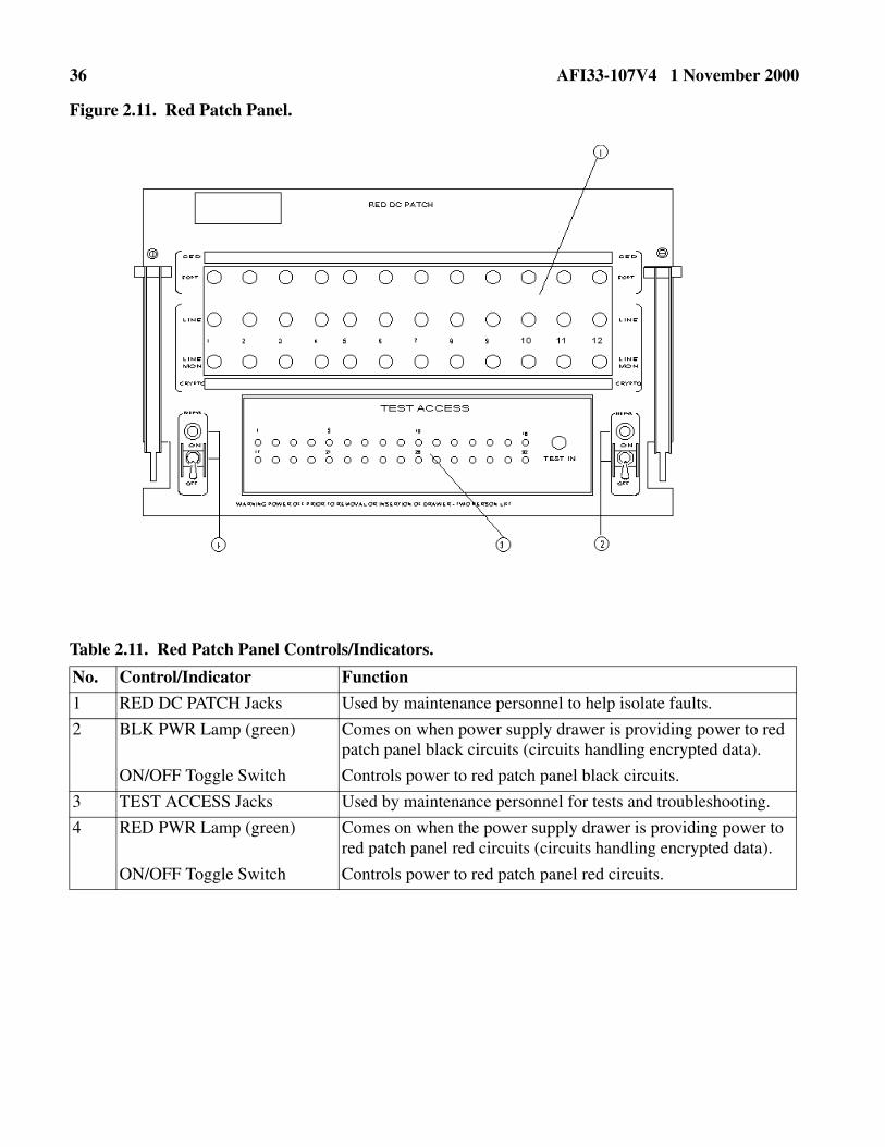
36 AFI33-107V4 1 November 2000
Figure 2.11. Red Patch Panel.
Table 2.11. Red Patch Panel Controls/Indicators.
No. Control/Indicator Function
1 RED DC PATCH Jacks Used by maintenance personnel to help isolate faults.
2 BLK PWR Lamp (green) Comes on when power supply drawer is providing power to red patch panel black circuits (circuits handling encrypted data).
ON/OFF Toggle Switch Controls power to red patch panel black circuits.
3 TEST ACCESS Jacks Used by maintenance personnel for tests and troubleshooting.
4 RED PWR Lamp (green) Comes on when the power supply drawer is providing power to red patch panel red circuits (circuits handling encrypted data).
ON/OFF Toggle Switch Controls power to red patch panel red circuits.

AFI33-107V4 1 November 2000 37
Figure 2.12. Black Patch Panel.
Table 2.12. Black Patch Panel Controls/Indicators.
No. Control/Indicator Function
1 BLACK DC/VF (Data Com-munications/Voice Frequency) PATCH Jacks
Used by maintenance personnel to help isolate faults. Communi-cations/Voice.
2 TEST ACCESS Jacks Used by maintenance personnel for tests and troubleshooting.

38 AFI33-107V4 1 November 2000
Chapter 3
AWCP/MUTE AND BCP FUNCTIONS
3.1. General. This chapter provides instructions on how to compose, store, retrieve, print, and transmitmessages. There are six MSU drives at the BCP and two MSU drives at the AWCP/MUTE. The sixMSUs at the BCP are numbered 02, 12, 22, 23, 24, and 25. The two MSUs at the AWCP/MUTE are num-bered 02 and 12.
3.2. Session Security Level.
3.2.1. The session security level menu (Figure 3.1.) automatically appears on the VDU screen afterthe AWCP/MUTE or BCP is IPLed or the CLR LVL key is pressed. When the security menu is dis-played, identify the classification and category (security level) by entering a legal three-digit codecombination from values shown on the menu. The first digit is the classification code; the second andthird digits are the category codes.
3.2.2. Change the session security level by pressing the CLR LVL key. This causes the security menuto be shown on the VDU screen. Press the numbers "1, 2, 6" and then the "ENTER" key. This putsthe master menu on the screen and the session security level of "UNCLASSIFIED/NOCAT" is estab-lished and displayed on VDU Line 21. All messages transmitted from this CUTE are at the"UNCLASSIFIED/NOCAT" security level until a different session security level is established. Thesession security level for this CUTE does not affect the receipt of messages.
3.2.3. Attachment 4 provides the entries and responses for establishing the session security level andshows the error conditions and corrective actions.
3.3. Master and Preformat Menus.
3.3.1. The master and preformatted menus are storage areas for user created messages stored for lateruse (e.g., ASORTIES, OPREPS, etc.). These messages are stored on the floppy diskette in the BCP orAWCP/MUTE MSU 12. Figure 3.2. and Figure 3.3. show the master and preformatted menus.
3.3.2. The master menu is displayed after establishing the session security level or when the menukey is pressed after the session security level has already been established. There are 26 places tostore messages on the master menu. The first four entries (01-MSU Retrieval/02-Header Comp/03Keyboard Test/04-Preformat Menu) are described in the following paragraphs. Entries 05 through 30are locations that are available for storing messages on the master menu.
3.3.3. The preformatted menu is an extension of the master menu. The preformatted menu isaccessed by requesting master menu entry 04. The preformatted menu has 30 locations available forstorage of messages.
3.3.4. Attachment 5 shows the entries, responses, error conditions, and corrective actions whenrequesting the master and preformatted menus.
3.4. Header Composition Menu.
3.4.1. The header composition menu provides a fixed format that may be used to create the headerpart of a message to be transmitted to the DTS. An experienced operator will create the header with-out using the header composition menu. Free-form message composition is described later.

AFI33-107V4 1 November 2000 39
3.4.2. Figure 3.4. shows the header composition menu as displayed on the VDU screen. The headercomposition menu is retrieved from the master menu by entering 02 and pressing the ENTER key.The header composition menu has protected fields with spaces for entries in each field. When anentry fills the field, the cursor is automatically moved to the start of the next field. If an entry does notuse all the spaces in the field or if the part number fields are not used, press the TAB key to move thecursor to the next field. Use the SHIFT and TAB keys to move the cursor to a previous field in orderto correct an error. The HOME key places the cursor at the start of the CLASSIFICATION entry. Ifan entry is rejected, VDU line 23 will display an error message. Move the cursor to the field in error,correct it, then move the cursor behind the last address entry. Now press the ENTER key. Attach-ment 6 has the procedure for using the header composition menu. Attachment 7 shows the associ-ated error conditions and corrective actions when using this menu. Make sure the session securitylevel of the CUTE is the same as the security classification and category code of the message header.
3.5. Free Form Message Composition. An experienced operator will compose an entire message with-out using the header composition menu. The message may be transmitted, stored, printed or deleted asrequired. Attachment 8 shows the entries and responses for free form message composition.
3.6. Text Composition.
3.6.1. The use of the header composition menu is followed by the message text. After the last char-acter in the message, enter the end of text character. Then transmit, store, or print the message withoutregard to the location of the cursor.
3.6.2. Limit your message length to 51 lines or less. The ETX character must be on line 51 or on aprevious line. After transmitting the message, a "FROM" line is added to the message. Total lengthof the message is checked to make sure it is not longer than 52 lines. If greater than 52 lines, the mes-sage is rejected and notification of the error is displayed on VDU line 23.
3.7. Master/Preformat Menu Storage/Modification/Deletion.
3.7.1. The user may compose messages and store them on the master or preformatted menus andrecall these messages at any time. Both CUTEs share the master and preformatted menus. If a mes-sage has a specific security classification level, establish that session security level before composingthe message. The session security level must be at the lowest security classification level allowed forthe message.
3.7.2. The boxed "L" (located on the STX key) and SHIFT keys will protect a character, space, orfield in a message. These protected characters, spaces, or fields are always transmitted in the message(e.g., ASORTIE ID and REQ items). To protect a character, space, or field, place the cursor at theposition to be protected and press the SHIFT and boxed "L" keys. Whatever is at that position is pro-tected and shown at a reduced intensity on the VDU screen.
3.7.3. Attachment 9 shows the steps and responses to store, modify, or delete a message on the mas-ter or preformatted menus. Attachment 10 shows the error conditions and corrective actions. Theformat of a stored message may be modified except for the protected characters, spaces, or data fields.The delete function erases a complete message from the menu diskette and the associated directory.The unused storage area is identified as usable via pointer for subsequent use.
3.8. AWCP/MUTE and BCP MSU 12 Storage Files.

40 AFI33-107V4 1 November 2000
3.8.1. Each CUTE is allowed to store 80 messages in the MSU storage area. The total character countof the 80 messages cannot exceed 180,992 characters. Each node can, therefore, store 160 MSU mes-sages. One CUTE cannot access the other CUTE's MSU messages. Establish the correct sessionsecurity level in regard to security classification of specific messages before composing and storingthese messages.
3.8.2. The boxed "L" and SHIFT keys are used to protect characters, spaces, or fields in a message.These protected characters, spaces, or fields are always transmitted in a message (e.g., ASORTIE IDand REQ items). To protect a character, space, or data field, place the cursor at the position to be pro-tected and press the SHIFT and boxed "L" keys. Whatever is at that position is protected and dis-played at a reduced intensity. Once you protect a character, space, or data field, you cannot change itunless you press the MEM CLR key (to blank the entire screen) or delete the complete message fromthe MSU storage file.
3.8.3. Messages located on the MSU storage file may be modified and deleted. Modifying lets youchange the format of the message except for protected characters, spaces, and data fields. The deletefunction erases a complete message from the menu diskette and the associated directory. The unusedstorage area is identified as usable via pointer for subsequent use.
3.8.4. There is no "menu" showing what messages are stored on the MSU storage files. When youstore a message on the MSU storage file, VDU Line 23 shows the MSU storage location numberwhere the message is stored. This same notice also prints on the LPU. Make up a directory listing thetitle of the message, the classification/category level, and the MSU storage location number. This willprovide a written record or reference guide of the messages and their storage location numbers. It issuggested that MSU 001 storage location be used for this purpose.
3.8.5. Keep a few empty MSU storage files available. This is helpful whenever a long message is tobe transmitted. Compose the message, store it, then transmit it. This procedure is also useful in theevent some addressees do not receive the message. Instead of retyping the message, just retrieve themessage from the MSU storage file and retransmit it.
3.8.6. Attachment 11 shows the steps to store, modify, and delete messages on the MSU storagefiles. Attachment 12 shows the associated error conditions and corrective actions.
3.9. Message Transmission.
3.9.1. After reviewing the message for accuracy and verifying all the message elements are present,you are ready to transmit the message. All characters in the message composition buffer (protectedand unprotected) displayed on the screen are transmitted.
3.9.2. Check the message for the following:
3.9.2.1. The session security level matches the security classification/category code in the mes-sage.
3.9.2.2. The STX character comes before the message text.
3.9.2.3. The message text is correct.
3.9.2.4. The ETX character follows the last character in the message to be transmitted.

AFI33-107V4 1 November 2000 41
3.9.3. When the message is ready for transmission, press the XMT button. If necessary, checkAttachment 13 for message transmission results, and Attachment 14 whenever an error messageappears on VDU line 23.
3.10. VDU Screen Printing. To print the contents of the VDU screen, the ETX character must be the lastcharacter on the screen. The print function allows the user to proof the message before transmitting it.The screen message is printed with both the top and bottom of each page marked with the session securitylevel shown on VDU line 21, regardless of the security classification in the message header (if a header ispresent). The screen print may be delayed if other incoming messages are being printed. If interrupted,the complete message will print when printing resumes. Attachment 15 shows the procedure for printingthe contents of the VDU screen and the associated error conditions and corrective actions.
3.11. Display Message Queue.
3.11.1. Messages are never forced to the user's VDU screen; however, certain situations require thatmessages are made available for the user's review. As a result, these messages are stored in a holdingarea or display message queue; a notice is output on VDU lines 21, 22, and 23 that there are messagesin the queue. Review each message in the queue by pressing the DSPL MSG key, once for each mes-sage. Messages are queued and displayed in order of message precedence, and within precedence, byorder of message arrival. The DSPL MSG key forces the session security level (line 21) to match thesecurity level of the message to be displayed next. As each message is displayed on the VDU screen,the status of the display message queue is changed (i.e., the number of messages in the queue isdecreased and the precedence level is changed to that of the next message in the queue).
3.11.2. Incoming messages are placed in the display message queue for the following reasons:
3.11.2.1. The LPU is down and an EAM message must be delivered to the user via the VDU.
3.11.2.2. A transmitted message failed to be accepted/delivered by the DTS and must be returnedfor corrections and/or retransmission.
3.11.2.3. User retrieval of a message from the master/preformatted menu or MSU storage filecould not be displayed because the session security level was lower than the security level of thestored message.
3.11.2.4. The session security level of the message to be stored is other than "UNCLASSIFIED/NOCAT." The master or preformatted menus are stored at the UNCLASSIFIED/NOCAT leveland the system must be returned to that level to update the menu.
3.11.3. The display message queue is stored in the CED-1. VDU actions (e.g., CLR LVL, MEMCLR, etc.) do not destroy the contents of the message queue. However, an IPL or RESTART actiondestroys what was in the display message queue.
3.11.4. Attachment 16 provides the display message procedures.
3.12. Message Reception.
3.12.1. The AWCP/MUTE and BCP receive messages from other DTS nodes. Non-EAM messagesare printed once on the LPU; EAMs are printed twice. Each printed page has a security banner withthe security classification and category of the message printed at the top and bottom. All characters,

42 AFI33-107V4 1 November 2000
with the exception of certain control characters (e.g., STX, ETX) are printed. Undefined characters(having no meaning) are printed with an error symbol.
3.12.2. The LPU may have been designated as an alternate printer for another CUTE. At the AWCP,the CUTEs are alternates for each other. At the MUTE, the accountable processor is the alternate. Fornon-EAM and EAM messages, if the printer is down at CUTE #1 and a message is about to be printed,a notification that the alternate destination has been initiated is displayed on VDU line 22 of CUTE#2. The messages are printed on CUTE #2's printer with the routing identifier of the primary destina-tion (CUTE #1) and the letter "N" as the last field of the FROM line in the message header. For EAMmessages, if the printers are down at CUTE #1 and CUTE #2, the messages are placed in the displaymessage queue and you are notified. You may then display these messages.
3.12.3. An EAM received and being printed (or placed in the display message queue) causes theEAM ACK switch to light and blink, the OPR ACK switch to light, and an audible alarm to sound.The audible alarm may be shut off in one of three ways: by timing out after approximately 10 sec-onds, by pressing the OPR ACK switch, or by pressing the EAM ACK switch. If the method used ispressing the OPR ACK switch, the first depression of the OPR ACK switch will turn off the audiblealarm, but does not affect the status of line 22 (i.e., if there is a notification in VDU line 22, it remainsand the OPR ACK switch remains lighted until a second depression of the OPR ACK switch. The fol-lowing steps must be used to acknowledge an EAM:
3.12.3.1. When the EAM audible alarm sounds, press the OPR ACK key to silence the alarm.
3.12.3.2. Review the message (either the hard copy on the printer or from the DSPL MSG queue)for validity based on regulations.
3.12.3.3. Press EAM ACK key to acknowledge receipt of the EAM.
3.12.4. For non-EAM messages received when the LPUs are down at CUTE #1 and CUTE #2, youare given a VDU line 22 notice with information that allows for retrieval of the message at a latertime.
3.12.5. Attachment 17 shows the procedures for non-EAM, alternate destination initiation or termi-nation, and EAM message receipt. Attachment 18 shows the associated error conditions and correc-tive actions.
3.13. Message Retrieval. Message retrieval is available for recovering messages from the origination ordestination accountable processor as a result of the AWCP/MUTE or BCP being down or when promptedby a notice on the VDU.
3.13.1. Messages journaled at the origination accountable processor (OAP) or destination account-able processors (DAP) can be retrieved to the destination or origination CUTE only. This procedurecan be used to retrieve messages that may have been addressed to you while your communication linewas down. Normally, the DAP will perform a "Deliver" of nondelivered messages for a node follow-ing a period of isolation from the network. The OAP or DAP for AWCP/MUTE CUTEs is its parentBCP or SCP. A BCP CUTEs DAP is always its own BCP. The OAP for BCP CUTEs could be its ownBCP or any one of the 16 other accountable processors in the network. Only those messages that orig-inated or were delivered to a specific CUTE can be retrieved by that CUTE. Retrieval of those mes-sages that originated or were delivered to another CUTE cannot be accessed by a different CUTE,with the exception of the Message Service Center (MSC) at the Offutt SCP.

AFI33-107V4 1 November 2000 43
3.13.2. One message or a group of messages may be specified for retrieval (e.g., all messages fallingwithin a given time period). If the number of messages exceeds the preset parameter of ten messagesper retrieval or the time default parameter of current time minus ten minutes is used, the retrieval pro-cess may be terminated before all desired messages are retrieved. If this occurs, enter a secondretrieval request with the DTG of the last retrieved messages as the new start DTG with the old stopDTG remaining the same.
3.13.3. Multiple entries (separated by a slash "/") are permitted for: the originating station routingindicator (OSRI) when the requesting CUTE is the destination routing indicator (DSRI), the DSRIwhen the OSRI is the requesting CUTE, and the message sequence number (MSN). Each field in aretrieval command is separated by a comma with no space. The total retrieval request cannot exceed72 characters in length.
3.13.4. The RET command is entered at the VDU/KB and is a valid command at all Functional Areas(FA). The retrieved messages are sent to the requesting VDU/KB's LPU. (To the Display MessageQueue when the VDU option is present.)
NOTE: Unless the requestor is SACMC (MSC), the requestor must be the originator or a destinationaddressee of the messages requested. There is a maximum of ten messages per retrieval request. Succes-sive retrievals must be a minimum of 30 seconds apart.
3.13.5. Attachment 19 shows the data field entries for message retrieval from a CUTE. The formatbelow provides the data fields for message retrieval.
Line 1=Field numbers Line 2=Field names Line 3=Field formats
CMD FIELD 1, FIELD 2, FIELD 3, FIELD 4, FIELD 5, FIELD 6
CMD OAP OSRI DSRI MSN DTG VDU
RET aaa aaacc aaacc nnn ddhhmmZ mmm/ddhhmmZ mmm
Field 1. (OAP) Required field. The OAP or DAP last three characters of the PROC address. This will be the processor from which the message will be retrieved.
Field 2. (OSRI) An optional field. The CUTE address that originated the message that you wishto retrieve. This field is repeatable when separated by a "/." Used to further define whichmessages are requested.
Field 3. (DSRI) An optional field. The CUTE address to which the message was addressed. Thisfield is repeatable when separated by a "/." Used to further define which messages arerequested.
Field 4. (MSN) An optional field. The MSN of the specific message that you wish to retrieve.This field is repeatable when separated by a "/." Used to further define which messagesare requested.
Field 5. (DTG) An optional field. The date time group range that you wish the accountable pro-cessor to search. When provided, specifies exact window of time to be searched. Whennot provided, the search is accomplished over the last 10 minutes from the time of theretrieval request.

44 AFI33-107V4 1 November 2000
3.13.6. An example of a retrieval request from an AWCP/MUTE could consist of the following:
3.13.7. The retrieval input shown above would be used to retrieve messages if an AWCP/MUTE hadbeen down or isolated from its accountable processor by line problems for 5 minutes or less. Thisexample shows the Altus AWCP/MUTE request to the Dyess BCP with defaults and permissibleomission. The processor would handle the request as if the following had been requested:
3.13.8. An example of a retrieval request from the Altus AWCP CUTE 01 could consist of the follow-ing:
3.13.9. The above retrieval input shows a request to the Dyess processor from the Altus AWCPCUTE 01 for two messages within the specified time frame. The OSRI was defaulted and the MSNwas repeated.
3.13.10. BCP CUTEs normally would not do retrievals when the processor is reestablished in the net-work. The originating accountable processors must do a DELIVERY for messages to CUTEs ataccountable processors. If originating BCPs/SCPs do not do a DELIVERY, then each addressedCUTE or subordinate processors of the BCP processor would have to do 16 retrieval requests, one toeach accountable processor in the network, to ensure that they get all messages that they missed.
3.14. Message Delivery. Message delivery is a capability only available at BCPs and SCPs. It is used torelieve the operator station from accountability of undelivered messages shown on the operator station.The BCP serves as the DAP for all local CUTEs and subordinate processors.
3.14.1. Messages stored on a BCP current or noncurrent journal can be searched for delivery of mes-sages to an OSRI or DSRI printer. The function is similar to the retrieval function but is restricted tothe BCP operator station. It is used when the operator outputs a NONDELIVERY NOTICE to a des-
Field 6. (VDU) An optional field. When used, the retrieved message will go to the Display Mes-sage Queue instead of the LPU. Field 4 (MSN) must be used with the VDU option, andonly one message may be requested.
FIELDS
CMD 1 2345 Format
RET YPU,,,, Input from ALT01 at 22 April at 1035Z
1 2 3 4 5
RET YPU,ALT01,ALT01,221030Z APR/221035Z
FIELDS
CMD 1 2 3 4 5 = Format
RET YPU,,ALT01,2549/0302,221243Z APR/221343Z APR = Actual Input
CMD FIELD 1, FIELD 2, FIELD 3, FIELD 4, FIELD 5, FIELD 6

AFI33-107V4 1 November 2000 45
tination processor (AWCP, HFSSB, Missile BCP, or MUTE) lost from the network due to a line out-age or the processor is inaccessible.
3.14.2. One message or a group of messages may be specified for delivery (e.g., all messages fallingwithin a given time period). If the number of messages exceeds the preset parameter of ten messagesper delivery or the time default parameter of current time minus 5 minutes is used, the delivery pro-cess may be terminated before all requested messages are delivered. To ensure that this does not hap-pen, count the number of messages for a specific destination and time period at the operator station. Ifmore than five messages exist, enter a second delivery request with the start DTG equal to or less thanthe fifth message time with the end DTG remaining the same.
3.14.3. Multiple entries (separated by a slash "/") are permitted for the OSRI, DSRI, and MSN. Eachfield is separated by a comma, but no spaces. The total delivery request cannot exceed 72 charactersin length.
3.14.4. The DEL command is entered at the SWOP, and is a valid command at the Accountable FA's"DEL" and is very similar to "RET" in its working and rules. The source of the message retrieval can-not be specified. By definition, the source is the node at which the request is made.
NOTE: Unless the Target RI is SACMC (MSC), the Target RI must be the originator or a destinationaddressee of the messages requested. There is a maximum of ten messages per retrieval request. Succes-sive retrievals must be a minimum of 30 seconds apart.
3.14.5. The format below provides the data fields for message delivery from a SWOP.
Line 1=Field numbers Line 2=Field names Line 3=Field formats
3.14.6. An example of a DELIVERY request from a BCP could consist of the following:
CMD FIELD 1, FIELD 2, FIELD 3, FIELD 4, FIELD 5,
CMD TGTRI OSRI DSRI MSN DTG
DEL aaacc aaacc aaann nnnn ddhhmmZ mmm/ddhhmmZ mmm
aaaaaaa aaaaaaa aaaaa
Field 1. (TGTRI) Required field. Where the retrieved messages will be delivered.
Field 2. (OSRI) An optional field. The CUTE address that originated the message that you wish todeliver. Used to further define which messages are requested. Not needed when MSN isincluded.
Field 3. (DSRI) An optional field. The CUTE address to which the message is addressed. Defaults toCUTE address of the TGTRI. Field may be repeated.
Field 4. (MSN) Required field. The MSN of the specific message that you wish to retrieve. This fieldis repeatable when separated by a "/."
Field 5. (DTG) An optional field. When provided specifies exact window of time to be searched.When not provided, the search is accomplished over the last 10 minutes from the time of theretrieval request.

46 AFI33-107V4 1 November 2000
3.14.7. The delivery input shown above would be used to retrieve messages if an AWCP/MUTE hadbeen down or isolated from its accountable processor by line problems for 5 minutes or less. Thisexample shows the Dyess BCP input with defaults and permissible omission. The processor will pro-cess the request as if the following had been requested:
3.14.8. The above delivery input shows a request from the Dyess BCP operator for two messageswithin the specified time frame. The OSRI and DSRI were defaulted and the MSN was repeated.
3.15. Operator Tests. Operational tests are categorized into manual operations performed on a specificpiece of equipment and tests or operations that are performed by software through operator inputs.
3.15.1. The following VDU and KB tests are available:
3.15.1.1. Screen Test. Press the SCRN TEST key and a test pattern of all displayable charactersis shown on the VDU screen. Alternate lines are shown at a reduced intensity. Check that the dis-play is correct. Press the SCRN TEST key again and the VDU display will return to its previousstatus. The SCRN TEST does not lose, alter, or transmit any user input data.
3.15.1.2. Lamp Test. Press the LAMP TEST key and all lamps not normally lighted (except forthe DC PWR FAIL lamp) on the VDU/KB are lighted and the audible alarm sounds. Check forany burned out light bulbs and that the audible alarm works. Press the LAMP TEST button againand all lamps are returned to their original state prior to the test and the audible alarm is turned off.The LAMP TEST does not lose, alter, or transmit any user input data.
3.15.1.3. Key Test. The key test ensures all the keys on the keyboard work correctly. It is used toidentify any nonfunctional keys. The only keys not tested are the repeat (RPT) and SHIFT keys.A key test may change the contents of the message composition buffer, so clear the buffer after akey test. The maintenance personnel will use this test to identify any problems with the key-boards.
3.15.1.4. The VMA Test. The VMA test button is on the front panel of the VDU. Pressing andholding the VMA test button causes the VMA to display the left one-third of the screen dark andthe right two-thirds bright (cursor) white. The display should be stable. When the test button isreleased, the display is restored to its original state. No data is lost, altered, or transmitted by per-formance of the VMA test.
3.15.2. The following commands are authorized for operator use to test and manage processor func-tions.
CMD 1 2 3 4 5 Format
DEL ALT01,SAC01,,0302, Input from Dyess BCP SWOP on 22 April at 1035Z
DEL ALT01, SAC01, ALT01,0302,221030Z APR/221035Z APR
CMD 1 23 4 5 Format
DEL ALT01,,,2549/0302,221243Z APR/221343Z APR Actual Input
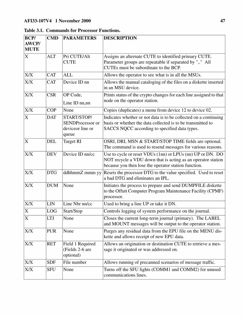
AFI33-107V4 1 November 2000 47
Table 3.1. Commands for Processor Functions.
BCP/ AWCP/ MUTE
CMD PARAMETERS DESCRIPTION
X ALT Pri CUTE/Alt CUTE
Assigns an alternate CUTE to identified primary CUTE. Parameter groups are repeatable if separated by ",." All CUTEs must be subordinate to the BCP.
X/X CAT ALL Allows the operator to see what is in all the MSUs.
X/X CAT Device ID nn Allows the manual cataloging of the files on a diskette inserted in an MSU device.
X/X CSR OP Code,
Line ID nn,nn
Prints status of the crypto changes for each line assigned to that node on the operator station.
X/X COP None Copies (duplicates) a menu from device 12 to device 02.
X DAT START/STOP/SENDProcessor or deviceor line or queue
Indicates whether or not data is to be collected on a continuing basis or whether the data collected is to be transmitted to SACCS NQCC according to specified data types.
X DEL Target RI OSRI, DRI, MSN & START/STOP TIME fields are optional. The command is used to resend messages for various reasons.
X/X DEV Device ID nn/cc Use to cycle or reset VDUs (1nn) or LPUs (nn) UP or DN. DO NOT recycle a VDU down that is acting as an operator station because you then lose the operator station function.
X/X DTG ddhhmmZ mmm yy Resets the processor DTG to the value specified. Used to reset a bad DTG and eliminates an IPL.
X/X DUM None Initiates the process to prepare and send DUMPFILE diskette to the Offutt Computer Program Maintenance Facility (CPMF) processor.
X/X LIN Line Nbr nn/cc Used to bring a line UP or take it DN.
X LOG Start/Stop Controls logging of system performance on the journal.
X LTJ None Closes the current long-term journal (primary). The LABEL and MOUNT messages will be output to the operator station.
X/X PUR None Purges any residual data from the EPU file on the MENU dis-kette and allows receipt of new EPU data.
X/X RET Field 1 Required (Fields 2-6 are optional)
Allows an origination or destination CUTE to retrieve a mes-sage it originated or was addressed on.
X/X SDF File number Allows running of precanned scenarios of message traffic.
X/X SFU None Turns off the SFU lights (COMM1 and COMM2) for unused communications lines.

48 AFI33-107V4 1 November 2000
X/X SWI None Switches the operator station function from the KSR-43 at a BCP or from the VDU at an AWCP to the VDU that inputs the command.
X/X TAB dev,table The TABLE command without parameters prints four tables: Destination Routing Table (DRT), Line Status Table (LST), Equipment Status Table (EST), and Processor Status Table (PST). Device is omissible. If omitted, printer 01 is the default. Enter the table name "aaa" if only a specific table is required.
X/X TES parm1,parm2 Provides the capability to test the following hardware items without taking the hardware offline or being required to do an IPL to run special software. No parm2 values are required with the following parm1 values: CPU and KSR. A parm2 value of device ID is required with the following parm1 values: LIN, VDU, and PRT. Device IDs, if unknown, can be obtained with a TAB LST and EST command.
X TOG ON or OFF Commands the BCP processor to journal all "X" precedence system control traffic. The default is OFF which reduces the amount of journal changes by as much as 386 percent.
X/X TRA As directed Restricted to unique situations requiring programmer interven-tion to trace specific actions within a processor. Implemented by specific message from SACCS NQCC/MSC.
BCP/ AWCP/ MUTE
CMD PARAMETERS DESCRIPTION
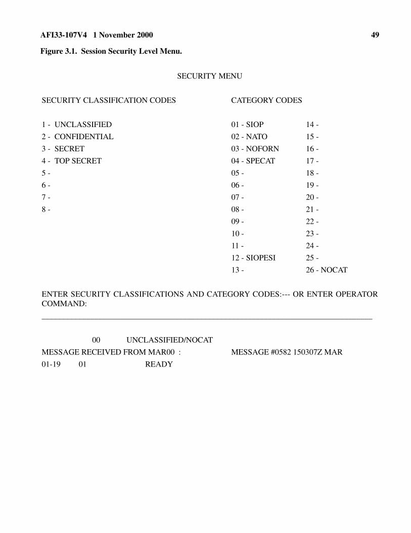
AFI33-107V4 1 November 2000 49
Figure 3.1. Session Security Level Menu.
SECURITY MENU
SECURITY CLASSIFICATION CODES CATEGORY CODES
1 - UNCLASSIFIED 01 - SIOP 14 -
2 - CONFIDENTIAL 02 - NATO 15 -
3 - SECRET 03 - NOFORN 16 -
4 - TOP SECRET 04 - SPECAT 17 -
5 - 05 - 18 -
6 - 06 - 19 -
7 - 07 - 20 -
8 - 08 - 21 -
09 - 22 -
10 - 23 -
11 - 24 -
12 - SIOPESI 25 -
13 - 26 - NOCAT
ENTER SECURITY CLASSIFICATIONS AND CATEGORY CODES:--- OR ENTER OPERATORCOMMAND:
__________________________________________________________________________________
00 UNCLASSIFIED/NOCAT
MESSAGE RECEIVED FROM MAR00 : MESSAGE #0582 150307Z MAR
01-19 01 READY

50 AFI33-107V4 1 November 2000
Figure 3.2. Master Menu.
MASTER MENU
01 - MSU RETRIEVEL 16 -
02 - HEADER COMP 17 -
03 - KEYBOARD TEST 18 -
04 - PREFORMAT MENU 19 -
05 - 20 -
06 - 21 -
07 - 22 -
08 - 23 -
09 - 24 -
10 - 25 -
11 - 26 -
12 - 27 -
13 - 28 -
14 - 29 -
15 - 30 -
ENTER TWO DIGIT SELECTION: _ _ R
__________________________________________________________________________________
00 UNCLASSIFIED/NOCAT
MESSAGE RECEIVED FROM MAR00 : MESSAGE #0582 150307Z MAR
ENTER ENTER MENU SELECTION
01-19 01 READY
NOTE: Master menu locations 05 - 30 may specify other titles.

AFI33-107V4 1 November 2000 51
Figure 3.3. Preformat Menu.
PREFORMAT MENU
01 - PACWX 16 -
02 - EURWX 17 -
03 - SORTS GEOLOC 18 -
04 - UPDATE 50MARG0 19 -
05 - 20 -
06 - 21 -
07 - 22 -
08 - 23 -
09 - 24 -
10 - 25 -
11 - 26 -
12 - 27 -
13 - 28 -
14 - 29 -
15 - 30 -
ENTER TWO DIGIT SELECTION: _ _ R
___________________________________________________________________________________
00 UNCLASSIFIED/NOCAT
MESSAGE RECEIVED FROM MAR00 : MESSAGE #0582 150307Z MAR
ENTER ENTER MENU SELECTION
01-19 01 READY
NOTE: Locations 05 - 30 may specify other titles.

52 AFI33-107V4 1 November 2000
Figure 3.4. Header Composition Menu.
HEADER COMPOSITION MENU
SECURITY CLASSIFICATION UNCLASSIFIED
SECURITY CATEGORY NOCAT
MESSAGE TYPE - -
EXTERNAL INTERFACE MESSAGE TYPE (OPTIONAL)
//- - - - - - - - - - - - - - - - - - -
PRECEDENCE -
PART FIELD (OPTIONAL)
MESSAGE PART NUMBER - -
TOTAL MESSAGE PARTS - -
ENTER ADDRESS:
____________________________________________________________________________________
00 UNCLASSIFIED/NOCAT
MESSAGE RECEIVED FROM MAR00 : MESSAGE #0582 150307Z MAR
ENTER ENTER HEADER PARAMETERS
01-19 01 READY
NOTE: SECURITY CLASSIFICATION AND SECURITY CATEGORY in Header Composition Menureflects Session Security Level shown on line 21.

AFI33-107V4 1 November 2000 53
Chapter 4
AWCP/MUTE AND BCP OPERATOR COMMANDS AND PROCEDURES
4.1. General. The SCPs serve as hubs for the network. They account for, record, and track all messagetraffic in the network. An SCP can only account for messages that it either originates or has deliveryresponsibility. An example of a message that an SCP would not have knowledge of would be a messageoriginated by, and sent from, the Minot BCP to the F.E. Warren BCP. The SCP operator at Offutt AFB NEhas the responsibility for controlling the entire network. The BCP operator has the responsibility of oper-ation of the BCP and controlling its subnet subscribers. The AWCP/MUTE operator has responsibility foroperation of the AWCP/MUTE. The operator's responsibilities include performing initial program loads,manual restarts of the system, changing diskettes, changing equipment configurations and responding tosystem prompts. This chapter describes the operator commands and procedures used at the AWCP/MUTE and BCP.
4.2. BCP Operator Station. The operator station at the BCP uses a KSR-43 teletypewriter for inputtingcommands and receiving system notifications. A CUTE (VDU/KB/LPU) may be used instead of theKSR-43 if the KSR-43 does not work. To assign the operator function to either the KSR-43 or a CUTE,refer to Attachment 20. The form and content for operator commands is the same, whether entered onthe KSR-43 or a CUTE.
4.3. AWCP/MUTE Operator Station. The operator station uses a CUTE (VDU/KB/LPU) for inputtingcommands and receiving system notifications. To assign the operator function to either CUTE, (AWCPONLY) refer to Attachment 20.
4.4. Operational Commands. Attachment 20 is a reference guide for operator commands. Shown arethe types, names, purpose, and complete descriptions of all operator commands at the AWCP/MUTE andBCP.
4.4.1. If the operator commands are entered using the KSR-43, the following events happen:
4.4.1.1. Enter a response number and action, or command, up to 72 characters in length.
4.4.1.2. Press the RETURN key on the KSR-43. The system will echo the response. This sendsthe command to the processor for acceptance and validation.
4.4.1.3. If the command is in error, an error message prints on the KSR-43 and the original com-mand will be requested again.
4.4.2. If the operator command is entered using the CUTE, the following events happen:
4.4.2.1. Press the CLR LVL key to display the security menu.
4.4.2.2. Press the TAB key to move the cursor to VDU line 19, column 1. This line is used toenter operator commands.
4.4.2.3. Enter a response number and action, or command, up to 72 characters in length.
4.4.2.4. Press the ENTER key on the CUTE keyboard. This sends the command to the processorfor acceptance and validation. Some responses to operator commands are also shown on VDU line22.

54 AFI33-107V4 1 November 2000
4.4.2.5. If the command is in error, an error message is printed on the LPU. Some error noticesare also shown on VDU line 22. NOTE: Output to the LPU for operator responses are groupedtogether and printed on a timed basis of 15 seconds. This reduces the amount of paper used at theLPU. This may cause a slight delay for responses to operator commands or notices requiringoperator action. Printer outputs produced by KSR-43/LPU at a BCP must be kept for 30days to provide the programming staff with essential information.
4.4.3. Several basic rules apply to operator commands:
4.4.3.1. The command is entered as the full word or as the first three letters of the word (e.g.,DEVICE or DEV).
4.4.3.2. A space is required after the command and before the first entry.
4.4.3.3. Values must be entered in a specific sequence and format, each separated by a comma,but no spaces. Double commas indicate an omitted entry (i.e., ",,"), unless it is the last entry in thecommand where no commas are required.
4.4.3.4. Multiple entries for a command are separated by slashes; for example, where more thanone line is down "LINE 08/09/10, DN."
4.4.3.5. Error messages that apply to all commands are in one of the following forms:
4.4.3.5.1. "DDHHMMZ EXCESSIVE/TOO FEW PARAMETERS ENTERED" indicates toomany or not enough entries in the command. Correct and re-enter the command.
4.4.3.5.2. "DDHHMMZ COMMAND NOT ALLOWED FROM YOUR STATION" indicatescommand that is not valid for this AWCP/MUTE or BCP. This notice is also output whenentering an operator command from the CUTE when the KSR-43 has been assigned theSWOP functions.
4.4.3.5.3. "DDHHMMZ INVALID PARAMETER - CORRECT .........." Correct the indicatedvalue/format and re-enter the command.
4.4.3.5.4. "DDHHMMZ INVALID INPUT COMMAND - CORRECT AND REENTER".
4.4.3.5.5. "DDHHMMZ YOUR LAST REQUEST DENIED: HARDWARE ERROR -RE-ENTER".
4.5. AWCP/MUTE and BCP Power Up Procedures. The "Power Up Checklist" (Attachment 25 orAttachment 26) shows the steps to power up the equipment. Use this checklist when all the equipmenthas been powered down (e.g., power failure, maintenance, etc.) and the equipment is to be brought backon-line.
4.6. AWCP/MUTE and BCP Power Down Procedures. The "Power Down Checklist" (Attachment25 or Attachment 26) shows the steps to power down the equipment. Use this checklist when all equip-ment has to be shut off (e.g., power failure and maintenance).
4.7. System Restarts and IPLs.
4.7.1. The system has the capability to detect inconsistent operation and software anomalies. Theseconditions are saved by the processor via the auto restart process. In those few instances where theprocessor cannot perform the restart or specific information is required by programmers, the operator

AFI33-107V4 1 November 2000 55
initiates a manual restart. IPLs are performed after a "power on" condition and as a last resort actiononly.
4.7.2. All system restarts or IPLs are reported automatically to SACCS NQCC by the processor as itperforms the action. These reports require follow-up action by SACCS NQCC to document thecause or reason, corrective action, and dump diskette number in their System Trouble MonitorReport. Conditions that can be cleared from the operator station that do not require restarts or IPLsrequire no follow-up action.
4.7.2.1. Non-IPL or Restart Conditions. The following are typical conditions that may beobserved by the operator that should not require an IPL or restart action. These conditions can becorrected by other procedures or need only be reported to the appropriate agency for action. Inthose instances where maintenance is notified, their actions normally should be to remove andreplace the failed component. In most cases, this can be done without powering down the BCP orAWCP/MUTE or requiring an IPL or restart.
4.7.2.1.1. VDU shows "I/O OUT" on VDU line 24. This condition can normally be correctedby a power down and up of the CUTE.
4.7.2.1.2. IPL diagnostics reports missing, failed, or unexpected equipment in the system.These notices are output before the DTG prompt is requested. Report problem to maintenanceand the appropriate headquarters agency.
4.7.2.1.3. Background diagnostics reports equipment failures during system operation. Ifpossible, do a manual test of the failed component with the appropriate operator command. Iffailure repeats, report problem to maintenance.
4.7.2.2. Restart. A restart is not a subset of the IPL. The reloading of the operational programsfrom the IPL diskette into the CED-1 computer memory does not take place and messages beingprocessed are not purged. A restart does not affect a local CUTEs display message queue or statusmessages. It does return each VDU to the security level menu. There are two types of restarts:automatic (auto) and manual. Reasons for either manual or auto restarts must be reportedto the SACCS NQCC when system is back to operational status.
4.7.2.2.1. Auto Restart. This type of restart is initiated by the processor. The only operatoraction required by this restart is to respond to the prompts output to the operator station,replace the DUMP diskette, record the removed diskette number for future reference, and pro-vide information when requested.
4.7.2.2.2. Manual Restart. A manual restart is initiated by the operator by depressing the"RSTRT" button on the CED-1 drawer. Manual restarts are used to collect data for specificproblems identified by programmers and correct system anomalies that cannot be corrected byoperator commands or actions. Subsequent operator actions for a manual restart are the sameas for an auto restart.
4.7.2.2.3. The CED-1 control panel shows a lighted "WAIT" or "ERROR" lamp. A "WAIT"condition usually indicates a software conflict and data must be collected via a manual restart.NOTE: The ERROR lamp illuminates whenever a dump is being taken for a restart condition.It should not last more than 30 seconds.
4.7.2.2.4. The SFU PROC fault lamp should illuminate at the same time the CED-1 ERRORlamp is on. There is a known condition where the ERROR lamp may be ON with the proces-

56 AFI33-107V4 1 November 2000
sor functioning normally. If the processor continues to perform without other fault indica-tions, no action is required. It will be corrected when a subsequent IPL is performed. If thereare unusual conditions, contact maintenance.
4.7.2.3. IPL. An IPL action loads all DTS programs from the IPL diskette into the CED-1 com-puter memory. Any information previously in memory is purged and the processor is set to an ini-tial state. All VDUs are refreshed and traffic being processed is terminated. There are two typesof IPLs: cold and EPU, with each satisfying specific requirements and conditions.
4.7.2.3.1. Cold IPL. A cold IPL is performed after a power up of the system hardware. Thereare instances where software changes will also dictate a cold IPL due to incompatibility of oneversion of software with another. A cold IPL must not be used as a means to correct perceivedsoftware or hardware problems. The input message format for an IPL is shown below.
4.7.2.3.1.1. An example of a cold IPL for a BCP could consist of the following:
The input shown above will cause the following output to be displayed on the KSR-43indicating a satisfactory IPL: 232145Z PROCHPU IS READY.SYSTEM ID:C000CB00.The ID shows the software release that the processor is running and must match thelabel on the diskette. If it does not, contact SACCS NQCC for instructions.
PROMPT FIELD1, FIELD2, FIELD3, FIELD4 = format
# DTG TYPE JNL JNL = field names
n ddhhmmZ mmmyy,c/e pri, alt = layout
n nnnnnnZ aaann c nn nn = value type
PROMPT The prompt number that is being answered for a specific processor request shouldnormally be "1". Not omissible.
Field 1. The current Zulu date-time-group when the processor is being IPLed. This time mustbe accurate as it is used to control the message journals. The day hour minute values are fol-lowed by the character "Z," then a space and the month and year. Not omissible.
Field 2. The type of IPL being performed. Only one value is permitted. C for cold or E forEPU. Not omissible or repeatable.
Field 3. BCPs only. The MSU number to be the current journal device at the BCP. This fieldis nonapplicable to AWCPs/MUTEs and is always omitted. This will be the first device thatthe processor uses to journal traffic. The default for a cold IPL is device 22.
Field 4. The MSU number to be the spare journal device at the BCP. This field is nonapplica-ble to AWCPs/MUTEs and is always omitted. This will be the next device that the processoruses to journal traffic. The default for a cold IPL is device 23.
PROMPT 1 2 3 4 Format
1 232145Z APR 91,C,22,23 Actual input from Whiteman BCP SWOP on 23 April at 2145Z

AFI33-107V4 1 November 2000 57
4.7.2.3.1.2. A more typical BCP IPL input would be the following and is what an AWCP/MUTE must always use, since it has no journal requirements.
NOTE: Fields 3 and 4 are omitted and that there is no "," after field 2.4.7.2.3.2. Warm IPL deleted.
4.7.2.4. EPU IPL. An electronic program update IPL is only performed when new software hasbeen electronically distributed to the BCP or AWCP/MUTE from Offutt AFB. An EPU IPLaccomplishes the same thing as a cold IPL. It also performs the additional task of combining soft-ware that has been received and transferred to a file on the menu diskette with that existing on theinstalled IPL diskette. NOTE: At the BCP, an EPU IPL does not save the current journal, so itmust be removed and replaced as part of the IPL process. This can be done with the LTJ commandjust before the EPU IPL.
4.7.2.4.1. The input message format for an EPU IPL is the same as that for a cold IPL. Theonly change is in field 2 where the value will always be "E" for EPU.
4.7.2.4.2. After the EPU IPL is completed, the processor must be IPLed again using the coldIPL procedure to implement the new software that is available on the updated IPL diskette.
4.7.2.4.3. The EPU procedures are provided in Attachment 22. Information about a specificEPU implementation will be provided in a separate message addressed to affected nodes.
4.8. BCP Journal Diskette Replacement. There are times when it will be necessary to change the jour-nal diskettes located in MSUs 22 and 23.
4.8.1. Journal Closure. As each journal is filled or at 2359Z of each day, the following notices areoutput to the KSR-43 or LPU. These notices or messages provide information and required actionsnecessary to manage the journal operations.
4.8.1.1. A label notice is output for each closure. It has the following format:
PROMPT 1 2 3 4 Format
1 241340Z APR 91,C Input from Beale BCP SWOP on 24 April at 1340Z
VAL1 VAL2 VAL3 VAL4 VAL5 VAL6
DDHHMMZ LABEL NN MMDDHHMMZ - MMDDHHMMZ SCTY CLASS
VAL1 The date the notice was generated and output to the operator station. It has the standardDay, Hour, Minute format.
VAL2 The word "LABEL" indicating that it is a current journal notice giving the information onhow to label the journal diskette that was just closed and identified in VAL3.
VAL3 The MSU device number that contains the journal diskette that was just closed and needsto be removed and labeled.
VAL4 The start time of the information contained on the journal diskette. This time could beearlier than the last journal close time if an accountable processor enters a wrong DTG atIPL time. Note that the format is Month Day Hour Minute Zulu.

58 AFI33-107V4 1 November 2000
NOTE: Label the removed diskette with the times shown in VAL1 and VAL2 or record on a log the dis-kette number and the start and end times. This information must be saved to perform retrievals.
4.8.1.2. A journal mount notice to replace the journal that was just closed out should be receivedand it has the following format:
4.8.1.3. Install a new (NOT previously used or degaussed) diskette in the specified MSU. Thisdiskette now becomes the spare journal. Switch the journal identifiers installed on each MSUdoor. The response to this journal mount notice is as follows:
4.8.1.3.1. Be aware that the processor does not respond with a confirmation output if the value"YES" is entered and a journal diskette is found. If "YES" is entered and a journal diskette isnot found or a "NO" response is entered, another mount request will be issued. It is imperativethat a current and spare journal be available to the system at all times. NOTE: A BCP will notfunction if it does not have journals.
VAL5 The end time of the information contained on the journal diskette. This time could belater than the time shown in VAL1 if an accountable processor entered the wrong DTGwhen the IPL was performed. Note that the format is Month, Day, Hour, Minute, andZulu.
VAL6 Shows the security classification of the journal. The classification will be that of the mes-sage with the highest classification logged on the journal.
PROMPT VAL1 VAL2 = format
# DTG JNL = field names
1 DDHHMMZM JOURNAL NN MOUNT = notice output
PROMPT The Prompt number to be answered for this specific processor request. This valuecan range from 1 to 9.
VAL1 The date the notice was generated and output to the operator station. It has thestandard Day, Hour, Minute format.
VAL2 The MSU device number where a journal diskette is to be installed.
PROMPT VAL1 = format
# RESPONSE = field names
n aaa = value type
PROMPT The Prompt number being answered for this specific processor response.
VAL1 The value "YES" or "NO" to indicate that a new journal diskette has or has not beeninstalled to replace the removed journal diskette.
An example of an actual response is shown below.
PROMPT VAL1 = format
1 YES = actual input at the Minot BCP

AFI33-107V4 1 November 2000 59
4.8.1.3.2. The following are examples of conditions caused by journals NOT being availableand are visible to the operator:
4.8.1.3.2.1. VDU shows "WAIT" or "BUSY" on VDU line 24 for an extended period (30seconds or more).
4.8.1.3.2.2. The operator does not respond to input messages or output any notices.
4.8.2. Journal Diskette Failure. If a journal diskette is bad and fails, the following notice will beprinted on the KSR-43 or LPU:
DDHHMMZ MSU XX MEDIA FAILURE: ISB=YY. CYCLE STEAL STATUS
ORDS = CCCCCCCCCCCCC.
DDHHMMZ LABEL XX MMDDHHMMZ - MMDDHHMMZ
N DDHHMMZ M JOURNAL XX MOUNT NEW JOURNALING VOLUMES
(N = 1, 2 or 3)
4.8.2.1. BCP MSU XX has failed and the maintenance codes indicating why it failed.
4.8.2.2. Line 2 of the notice specifies the current date-time-group, the BCP MSU journal positionof the bad diskette, and the label to write on the bad diskette (MMDDHHMMZ - MMDDH-HMMZ). The label will show the time span when journaling started and when it stopped becauseof the diskette failure.
4.8.2.3. Line 3 of the notice is a prompt to mount a new journal diskette in the BCP MSU journalposition (XX).
4.9. BCP Stored Journal Message Retrieval. The BCP and its subnet subscribers have the capability toretrieve messages from dismounted journals placed in storage. When the information to be retrieved can-not be located on the current journals on MSU 22 or 23, a notice is output on the KSR-43/LPU to mountone of the stored journals. Attachment 19 lists the steps to retrieve the journaled messages.
4.10. Throttling. When the CED-1 computer memory for processing messages is used up, throttling oflower precedence messages may be required.
4.10.1. Throttling relieves congestion on saturated communication lines by not allowing low prece-dence messages to pass through the AWCP/MUTE and BCP until more computer memory is avail-able.
4.10.2. The notice that throttling is in effect or has been terminated will be printed on the BCPKSR-43/LPU and/or the AWCP/MUTE LPU. This notification appears as:
DDHHMMZ THR cccc PROCppp nn%
cccc = INIT or TERM. PROCppp = processor which initiated throttling; (may or may not be theAWCP/MUTE and/or BCP) and nn = numerical value for the throttling or termination condition.
4.10.2.1. INIT stops routine precedence messages from passing through the AWCP/MUTE orBCP until more memory is available. All higher precedence messages and EAMs are allowed topass through the AWCP/MUTE or BCP.

60 AFI33-107V4 1 November 2000
4.10.3. If throttling status levels do not decrease, the system initiates an auto Restart to clear up thethrottling problem.
4.11. Status Table Printouts. There are two figures indicating status of the equipment and communica-tion lines. These figures are to be used with the fault troubleshooting charts in your Operator's Guide.
4.11.1. Figure 4.1. shows the AWCP/MUTE or BCP Line Status Table. This figure provides the sta-tus of the BCP communication lines to the SCP and its subnet subscribers or the status of the AWCP/MUTE communication lines to the BCP/SCP. This figure also shows the status of the modems andthe KG-84A cryptos.
4.11.2. Figure 4.1. shows the Equipment Status Table. This figure provides the status of the LPUs,VDUs and MSUs.
4.12. Copy Menu Diskettes. The "COPY" function allows the operator to copy menu diskettes duringon-line operations without disrupting the system. The copy function takes about 2 minutes to completeand during this time the operator must not modify the menu diskette.
4.12.1. Do not try to copy a menu diskette when an EPU or remote dump is in progress.
4.12.2. Do not try to do an EPU or remote dump when the copy function is in progress.
4.12.3. The menu diskette being copied must be in Drive D12.
4.12.4. The menu diskette you are copying the menu to must be in Drive D02.
4.12.5. To begin the "COPY" function, type the word "COPY" at the SWOP/VDU. The programprompts the operator to insert the proper diskettes into their specific drives. If a dump diskette isassigned to Drive D02, go ahead and remove it.
4.12.6. A menu diskette must be in Drive D02 before entering "Y" to the prompt. This "Y" promptbegins the copy process and cannot be interrupted.
4.12.7. If you are not ready for the copy function or want to delay it, enter "N" to the prompt.
4.12.8. After the copy is made, you must place the removed diskette back in the drive it was previ-ously assigned.
4.12.9. Examples of the "COPY" function are shown here with the different program responses:
4.12.9.1. This example illustrates a delay or abort of the copy function.
4.12.9.2. In this example, the operator answers "Y" to the prompt, but the read drive is not ready.The drive may be bad or has a bad menu diskette.
COPY
111114Z COPY
111114Z PLACE MENU IN D12 AND DESTINATION IN D02
1 N
111114Z COPY FUNCTION ABORTED

AFI33-107V4 1 November 2000 61
4.12.9.3. In this example, the write was invalid because Drive D02 may be bad or it has a bad des-tination menu diskette. Try another diskette and start over.
4.12.9.4. In this example, the operator receives a "DEST NOT VALID" message. Remove yourIPL, DUMP, or other non-MENU diskette from Drive D02. When you receive a "MENU NOTVALID" message, make certain a menu diskette is in Drive D12; otherwise, the copy function willbe terminated.
COPY
111115Z COPY
111115Z PLACE MENU IN D12 AND DESTINATION IN D02
1 Y
111116Z UNIT NOT READY MSU 12
111116Z MSU 12 MEDIA FAILURE:ISB=80 CYCLE STEAL STATUS
WORDS=0-1E6F 1-0400 2-1006 3-0001
111116Z READ NOT VALID....COPY FUNCTION ABORTED
COPY
111116Z COPY
111116Z PLACE MENU IN D12 AND DESTINATION IN D02
1 Y
111116Z UNIT NOT READY MSU 02
11111Z MSU 02 MEDIA FAILURE:ISB=80 CYCLE STEAL STATUS
WORDS=0-1DE3 1-0400 2-1006 3-0001
111117Z WRIT NOT VALID....COPY FUNCTION ABORTED
COPY
111117 COPY
111117Z PLACE MENU IN D12 AND DESTINATION IN D02
1 N
111118Z COPY FUNCTION ABORTED
COPY
111120Z COPY
111120Z PLACE MENU IN D12 AND DESTINATION IN D02
1 Y
111120Z MSU 12 UP
111120Z MENU NOT VALID....COPY FUNCTION ABORTED

62 AFI33-107V4 1 November 2000
4.12.9.5. This example indicates a successful copy function.
4.13. Catalog Command/Auto Catalog. The CATALOG command provides the user, operator, andmaintenance personnel with the capability to manually determine the diskette volume currently mountedin a specific device by referencing the device in question. Execution of the CATALOG command willdeliver to the operator station (for all devices specified) a printed response identifying the diskette volumein the referenced devices. In addition, AUTO CATALOG will automatically provide, when the MSUdoor is closed, the system notification for selected diskettes (MENUs and DIAGNOSTICS) which isrequired for operational access to these diskette volumes. This will allow for the changing of disketteswithin a specified device, if required for operational or maintenance purposes. This includes changing aMENU diskette or replacing a diskette with a diagnostics diskette for performing maintenance functions.Again, following replacement of a diskette to meet either of the above operational needs, the AUTO CAT-ALOG function will automatically catalog the new diskette when the MSU door is closed. This actionnegates the current need to perform an IPL when these diskettes are changed.
4.13.1. The catalog capability, manual or automatic, does not in any way change or replace proce-dures already established and in effect for changing DUMPFILE, or JOURNAL diskettes, or movingthem to another device. The normal response to system prompts is still required to assign DUMP-FILE and JOURNAL diskettes for system use.
4.13.2. The following diskette volume names will be identified when the catalog command is used.The volume name is what is printed at the operator station. The files listed with each volume nameindicates the "dataset" names contained in each volume.
COPY
111120Z COPY
111120Z PLACE MENU IN D12 AND DESTINATION IN D02
1 Y
111122Z COPY FUNCTION SUCCESSFUL
VOLUME FILES
IPL 1ACMIS
1ACMDS
PERMFILE
MENUS JNLINDEX
EPUFILE
MENUS
DUMPFILE DUMPFILE
EMPTY
JOURNAL JOURNAL
DIAG03 FOOODF01

AFI33-107V4 1 November 2000 63
4.14. Catalog Format and Legal Values. The catalog command has the following format:
4.14.1. An example of the CATALOG command is as follows:
4.14.2. The device ID is not repeatable or omissible. If omitted, repeated, or an illegal value is used,an error message is output. A legal device ID but invalid for a specific node will also result in an errormessage to be output.
4.14.3. The format of the message output indicating the diskette may or may not be removed from thedevice, is as follows:
4.14.4. CAUTION! Removal and replacement of a diskette identified with the modifier "LOCKED"with a diskette containing a different file structure may cause the processor to become confused and
FOOODF02
FOOODF11
FOOODF12
FOOODF71
FOOODF72
FOOODF81
FOOODF82
FOOODF91
FOOODF92
FOOODFA1
FOOODFA2
COMMAND ID
where COMMAND = CATALOG or CAT and
ID = a MSU device ID, legal ID values = 02,12,22,23,24,25
CATALOG 12 or CAT 12
ddhhmmZ DEVICE nbr CONTAINS volume id, locked
where nbr = device ID number, volume id = volume name of diskette, and
locked = indicates privileged rights to a file, and the diskette must NOT be removed.
No value or absence of the word "LOCKED" indicates diskette may be removed.
An example of the output message is as follows:
ddhhmmZ DEV 12 CONTAINS MENUS
VOLUME FILES

64 AFI33-107V4 1 November 2000
abnormally terminate all processing. If this must be done, ensure that the original diskette or one oflike structure is replaced as soon as possible.
4.15. Normal and Special BCP Catalog Procedures. The CATALOG command will verify the con-tents of a diskette within a specific device without physically removing the diskette. It also allows forchanging a MENUS diskette at all processors and allows maintenance personnel to install a diagnosticsdiskette to verify the device is operating correctly.
4.15.1. For all devices that do not contain "LOCKED" diskettes, the following procedure is used tochange a diskette:
4.15.1.1. Determine which diskette device is to be verified, changed, or tested.
4.15.1.2. Perform a catalog command on the selected device prior to removing the diskette toconfirm that it has no "LOCKED" files and that it is not a DUMPFILE or JOURNAL.
4.15.1.3. If the device is not "LOCKED" and it is the diskette to be replaced, remove it and insertthe desired diskette.
4.15.1.4. Auto catalog establishes the new diskette structure within the processor when the MSUdoor is closed.
4.15.2. Special procedures may be necessary for the BCP whenever DUMPFILE and JOURNAL dis-kettes need to be replaced for diagnostics testing. Special procedures must be followed to precludesystem impact or to understand system notices.
4.15.2.1. If a DUMPFILE diskette is to be replaced with a diagnostics diskette, perform the stepsas shown in paragraph 4.15.1.
4.15.2.2. If an AUTO or MANUAL RESTART is performed, a NO DUMP will be taken and thefollowing notice will be output to the operator station.
4.15.2.3. When the diagnostics test is completed, return the DUMPFILE diskette to its originallocation. It will be automatically cataloged when the MSU door is closed. Subsequent restartswill then be captured on the DUMPFILE diskette with proper notification.
4.15.2.4. Testing of a JOURNALING device with a diagnostic diskette must be restricted to thespare JOURNALING device only. Testing of the current JOURNALING device must be delayeduntil this journal terminates because of journal full, RADAY, or physical problems causing termi-nation.
ddhhmmZ RESTART DUE TO xxxxxxxxxxxxxxxxxxxxxx. NO DUMP
PSW IAR AKR LSR R0 R1 R2 R3 R4 R5 R6 R7
nnnn nnnn nnnn nnnn nnnn nnnn nnnn nnnn nnnn nnnn nnnn nnnn
PID: vvvv vvvv vvvv vvvv
where xxxxxx = the cause of the restart
nnnn = register values
vvvv = Program ID, Accountable processor, process nbr, security level

AFI33-107V4 1 November 2000 65
4.15.2.5. To test the spare JOURNALING device, review the operator station printout to seewhich device had the last journal mount. This will be the spare JOURNALING device. The dis-kette in this device can be verified to be a journal diskette by executing the catalog command forthis device. The CATALOG command will not identify which journal diskette is primary or alter-nate. This can be determined only by review of previous SWOP output.
4.15.2.6. Following diskette verification, replace the journal diskette with a diagnostic diskette.
4.15.2.7. If the diagnostic test is successful, replace the diagnostic diskette with the removed jour-nal diskette. Auto catalog will reassign the journal diskette for use as a spare journal.
NOTE: This reassignment of a journal diskette by Auto catalog can only be accomplished for a journaldiskette that has previously been assigned to the device in question by answering a system prompt.
4.15.2.8. If the diagnostic test shows the MSU is bad, call maintenance. The spare journal can bereassigned to an alternate MSU.
**CAUTION****CAUTION****CAUTION**
4.15.2.9. If the BCP does not have a spare journal and the current journal terminates, the proces-sor will run out of memory and require a restart.
4.16. Catalog Problem Notice Outputs. The following catalog problem notices are output to the opera-tor station. The possible cause for the catalog problem notice and the actions that may correct the problemare shown here.
4.16.1. Catalog problem notice number one:
ddhhmmZ INVALID PARAMETER - CORRECT
where parameter = the invalid value.
4.16.1.1. The operator entered a value that is legal but not valid for this FA.
4.16.1.2. The parameter value is illegal, not a two digit MSU device ID.
4.16.1.3. The device ID of 48 was entered and is illegal.
4.16.1.3.1. Review legal device IDs for this specific FA.
4.16.1.3.2. Re-enter two digit value of 02,12,22,23,24, or 25.
4.16.2. Catalog problem notice number two:
ddhhmmZ DEVICE id IS UNREADABLE
4.16.2.1. Possible device failure caused by door open longer than 30 seconds or no power to thedevice.
4.16.2.2. Possible media failure caused by bad or scored track on diskette, improperly formatteddiskette, wrong type diskette, or degaussed diskette.
4.16.2.2.1. Confirm device is powered on and there is no SFU fault light.
4.16.2.2.2. Review operator station printouts for advisory: "ddhhmmZ CLOSE COVER ONdev id" indicating open door. Confirm door is closed.

66 AFI33-107V4 1 November 2000
4.16.2.2.3. Review operator station printouts for additional information like "ddhhmmZUNINITIALIZED OR DAMAGED DISKETTE IN dev id [SLOT n]."
4.16.2.2.4. If no notices printed, remove diskette for visual inspection for scores andscratches. Discard and replace any damaged diskette.
4.16.2.2.5. Perform catalog command to confirm correction.
4.16.3. Catalog problem notice number three:
ddhhmmZ DEVICE id IS UNAVAILABLE (id = device number)
4.16.3.1. A file on the specified diskette (location) is active (open) making the diskette an invalidcandidate for removal.
4.16.3.2. If diskette is removed or replaced, unpredictable results may occur.
4.16.3.2.1. DO NOT remove any diskette from a location that is marked UNAVAILABLE.
4.16.3.2.2. Take operator/user actions to close any open files on a diskette if device must beused. An example is a MENU diskette being modified.
4.16.3.2.3. Verify files closed by using catalog command.
4.16.4. Catalog problem notice number four:
ddhhmmZ structureid LIST SIZE IS INSUFFICIENT. NOT ALL filetyp WILL BE AVAILABLE
structureid = PARTITIONED or FILE or MEMBER
filetyp = DATASET or VOLUME or MEMBERS
4.16.4.1. The operator/user has configured the processor with an invalid diskette configuration.Most probable cause is more than one MENU diskette cataloged.
4.16.4.1.1. Review installed diskette configuration to ensure that it conforms to authorizedstructure. Replace invalid diskette.
4.16.4.1.2. Perform catalog command on all devices that have had diskettes replaced.
4.16.4.1.3. Verify following notice output to operator station:
ddhhmmZ structureid LIST SIZE HAS BEEN RESTORED
4.16.5. Catalog problem notice number five:
ddhhmmZ structureid LIST SIZE HAS BEEN RESTORED
4.16.5.1. The operator/user has performed a catalog command after realigning diskettes.
4.16.5.2. The system was able to accept and maintain all listed structure IDs.
4.16.5.3. No corrective actions are needed.
4.16.6. Catalog problem notice number six:
No listing of device contents after the echo of the catalog command.
4.16.6.1. When directory manager performs the catalog function, it is a serial process.

AFI33-107V4 1 November 2000 67
4.16.6.2. If there is a previous (still active) PROMPT that has not been responded to, there will beno output in response to this command.
4.16.6.2.1. Review operator station printouts for outstanding (unanswered - active)PROMPTS.
4.16.6.2.2. If none found, enter at operator station n ????? at least three times with "n" hav-ing the values of 1, 2, and 3, respectively.
4.16.6.2.3. Respond to PROMPT requests as directed, if any.
4.16.6.2.4. If all, respond with:
ddhhmmZ RESPONSE NUMBER n: NOT ACTIVE
then an answered PROMPT is not the problem.
4.16.6.2.5. Review operator station output for other notices that explain the condition such asuncompleted diagnostic functions.
4.17. Remote Data Transmission (RDT). This process is used to transmit information written to aDUMP (created during a restart) or JOURNAL diskette to CPMF at Offutt AFB NE. Refer to Attach-ment 23.
4.18. Diskette Name Change for Journal Transmission. This process renames remote data-dump dis-kettes that were used for transmission to CPMF. It renames this transmission diskette back to JOURNAL.Refer to Attachment 24.
4.19. Systems Notification Messages. Systems notification messages are listed in Attachment 21.
Figure 4.1. Line Status.
*******UNCLASSIFIED/NOCAT***********
1
NODE-PROCCPU 251335Z MAR
2 3 4 5 6 7 8 9 10 11
LINE LNE CON ROUTING -STATUS-- RESYN -CRC- STATUS ERR -FAILURE COUNTS BY TYPE
-ID- TYP TYP INDICTR LNE MOD CRY THRSH THRSH TIME- TYP INF CRY MOD OPR PRO TRA
13 DED SCP PROCMPX UP UP UP 7 16 251333 MOD 0 0 1 0 0 0
16 DED BCP PROCAPU UP UP UP 7 16 251333 MOD 0 0 1 0 0 0
17 DED AWP PROCCPA UP UP UP 7 16 251333 INF 1 0 0 0 0 0
20 DED MBC PROCCPR UP UP UP 7 16 251333 INF 1 0 0 0 0 0
21 DED MBC PROCCPB UP UP UP 7 16 251333 MOD 0 0 1 0 0 0
*******UNCLASSIFIED/NOCAT***********
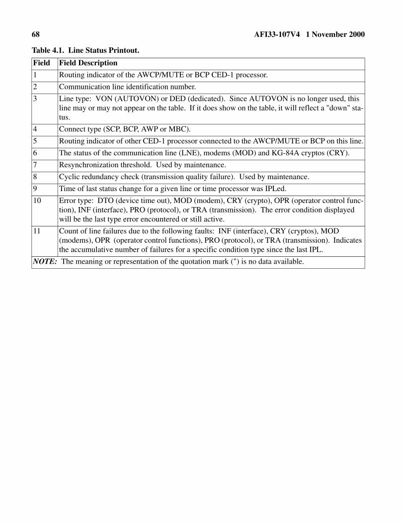
68 AFI33-107V4 1 November 2000
Table 4.1. Line Status Printout.
Field Field Description
1 Routing indicator of the AWCP/MUTE or BCP CED-1 processor.
2 Communication line identification number.
3 Line type: VON (AUTOVON) or DED (dedicated). Since AUTOVON is no longer used, this line may or may not appear on the table. If it does show on the table, it will reflect a "down" sta-tus.
4 Connect type (SCP, BCP, AWP or MBC).
5 Routing indicator of other CED-1 processor connected to the AWCP/MUTE or BCP on this line.
6 The status of the communication line (LNE), modems (MOD) and KG-84A cryptos (CRY).
7 Resynchronization threshold. Used by maintenance.
8 Cyclic redundancy check (transmission quality failure). Used by maintenance.
9 Time of last status change for a given line or time processor was IPLed.
10 Error type: DTO (device time out), MOD (modem), CRY (crypto), OPR (operator control func-tion), INF (interface), PRO (protocol), or TRA (transmission). The error condition displayed will be the last type error encountered or still active.
11 Count of line failures due to the following faults: INF (interface), CRY (cryptos), MOD (modems), OPR (operator control functions), PRO (protocol), or TRA (transmission). Indicates the accumulative number of failures for a specific condition type since the last IPL.
NOTE: The meaning or representation of the quotation mark (") is no data available.

AFI33-107V4 1 November 2000 69
Figure 4.2. Equipment Status.
Table 4.2. Equipment Status Report.
*******UNCLASSIFIED/NOCAT***********
NODE-PROCCPU 251335Z MAR
COUNTS OF FAILURE BY TYPE - CUMULATIVE TIME
1 2 3 4 5 6 7 8 9 10 11
EQUIPMNT STA TIME CON CURRENT STATUS -CHANNEL- -TIMING- -CONTROL- -OPERATOR-
ID. TYP TUS OUT NCT FAILURE -TIME- COUNT TIME COUNT TIME COUNT TIME COUNT TIME
1 LPU UP NO YES " 251333 0 0 0 0 0 0 0 0
2 LPU UP NO YES " 251333 0 0 0 0 0 0 0 0
1 VDU UP NO YES " 251333 0 0 0 0 0 0 0 0
2 VDU UP NO YES " 251333 0 0 0 0 0 0 0 0
12 13 14 15
DEVICE ERR DCB CHECK STORAGE CK INTRFCE CK
COUNT TIME COUNT TIME COUNT TIME COUNT TIME
2 MSU UP NO YES " 251333 0 0 0 0 0 0 0 0
12 MSU UP NO YES " 251333 0 0 0 0 0 0 0 0
22 MSU UP NO YES " 251333 0 0 0 0 0 0 0 0
23 MSU UP NO YES " 251333 0 0 0 0 0 0 0 0
24 MSU UP NO YES " 251333 0 0 0 0 0 0 0 0
25 MSU UP NO YES " 251333 0 0 0 0 0 0 0 0
Field Field Description
1 Equipment ID assigned by software and used by the AWCP/MUTE or BCP CED-1 processor to control, monitor, and report status.
2 Device ID number for associated equipment type. Used with operator commands and notices. If used, precede single digit with "0." VDU Device IDs are preceded by a "1" to make a 3-digit number.
3 Equipment status (up or down).
4 Equipment time out (yes or no).
5 Connectivity status for switchable CUTEs. Will always be "YES" for BCPs and AWCPs/MUTEs.
6 This will show one of the conditions of columns 8 through 15 in abbreviated form.
7 Time of last status change for a given equipment ID or time processor was IPLed.

70 AFI33-107V4 1 November 2000
8-15 The COUNT column contains the accumulative failures since IPL for the identified failure type. The TIME column shows in seconds the elapsed accumulative time for the identified failure since the last IPL. OPERATOR counts are caused by the DEVICE command. The Device Con-trol Block (DCB) column counts the checks.
NOTE: MSU IDs 22, 23, 24, and 25 are installed at BCPs only
Field Field Description

AFI33-107V4 1 November 2000 71
Chapter 5
SACCS DESKTOP-TERMINAL
5.1. General. The SDT extends the rapid and reliable message delivery capabilities of the SACCS todesktop personal computers (PC). The SDT utilizes commercially available hardware and software toemulate many of the functions provided by the unique SACCS hardware and software. Using the SACCSnetwork as a communications backbone, the SDT makes it possible to provide this message deliverycapability to many more users with the reduced maintenance costs, smaller physical size requirements,and greater user familiarity inherent in a PC.
5.2. SDT Capabilities.
5.2.1. The SDT provides rapid, reliable delivery of text messages via the SACCS network. Interfacesconnecting SACCS to AUTODIN DTH, the Strategic Force Accounting Module, the CCPDS, and theStrategic War Planning System enable SDT users to communicate with these other communicationssystems.
5.2.2. Incoming messages at the SDT are printed upon receipt on a dot matrix printer. Outgoing mes-sages are composed and transmitted via a commercial word processor. A ‘Comeback Copy’ of atransmitted message is printed on the dot matrix printer. This 'Comeback Copy' is printed upon thereceipt of an acknowledgment that it was received by SACCS. The SDT makes three attempts totransmit a message. If an acknowledgment is not received after the third transmission, the operator isnotified that the message was not delivered to SACCS.
5.2.3. Printed messages contain the MSN and DTG assigned by SACCS. There is no permanent stor-age of incoming messages on the SDT’s hard drive.
5.3. SDT Components.
5.3.1. The SDT consists of a desktop PC containing a High-Level Data Link Control (HDLC) inter-face card connected to a Secure Telephone Unit (STU-III) crypto device via a RS-232 cable. TheSTU-III connects to a 2-wire leased telephone line via a RJ-11 connector. This dedicated telephoneline connects the SDT to a single SACCS node, that provides the SDT with access to the entireSACCS network plus the communications systems interfacing to SACCS.
5.3.2. The SDT is equipped with a removable hard drive kit for easy removal and storage.
5.3.3. A dot matrix printer completes the SDT equipment suite.
5.3.4. The SDT uses the Microsoft Windows 98 operating system and Microsoft Word 97 providesthe operator interface to compose, store, edit, and transmit outgoing messages. The SDT Communi-cations Program provides communications with the SACCS network by emulating the SACCS mes-sage handling protocols within the SDT.
5.4. SACCS Transmit Program.
5.4.1. The SACCS Transmit program uses toolbar buttons and dialog boxes to create, store, and trans-mit messages to SACCS. The program consists of Microsoft Word 97 running a unique set of macrosand is started by double clicking on the Microsoft Word icon with the name SACCS Transmit.

72 AFI33-107V4 1 November 2000
5.4.2. The program opens a template file for Read-Only access and runs within a large white windowat the top of the screen. The name in the title bar of the window is Microsoft Word – SACCS.DOT(Read-Only). This program can be terminated by the operator, but any changes made to the templatefile (intentional or accidental) cannot be saved. The Close button on the toolbar saves any changesmade to the displayed message before closing the file. To close the displayed message without savingchanges, use the File|Close menu option on the menu bar or the Close Window (X) button on the farright-hand side.
5.5. SDT Communications Program.
5.5.1. The SDT Communications Program manages all communications, both send and receive, withSACCS. The program is started by double clicking on the icon that looks like a monitor. The icon hasthe name of the site and processor routing indicator (RI). Ensure that the program is not currently run-ning with its window minimized by checking the task bar. Running two copies of this program simul-taneously causes serious communications problems.
5.5.2. The program runs within a dark blue colored window at the bottom of the screen. The name inthe title bar of the window consists of the site and processor RI, such as Lincoln – PROCOPF. Thebackground color of the status line is green when the line is up and red when the line is down or whenan error has been detected. Press a key, such as the space bar, to clear an error notice and return to theline status display.
5.5.3. The program can be terminated by pressing the Escape key, then pressing the Y key inresponse to the Do you want to terminate this program? (Enter y / n) prompt. If the program ter-minates itself, an error notification appears in the window. Include the exact text of this error notifi-cation when reporting a problem to the NQCC.
5.6. SACCS Network Configuration.
5.6.1. The SACCS network consists of several different types of nodes. Each SDT is connected toeither a SCP or a BCP, that serves as the SDT’s parent accountable processor. The SCP or BCPassigns a MSN and DTG to a message transmitted from an SDT. It then stores the message on an8-inch floppy diskette, and accepts accountability for delivering it to all addressees. A messageaddressed to a SDT must first be delivered via the SACCS network to the parent SCP or BCP, whichthen journals the message on an 8 inch floppy diskette and delivers it to the SDT.
5.6.2. Due to the limited number of communication ports at the SCPs and BCPs, the SDT is notdirectly connected to the parent accountable processor. Each SDT connects to a PEP located along-side and connected to the BCP or SCP. The PEP enables four SDTs to connect to the SCP or BCP viaa single communication port.
5.6.3. The SCP and BCP operators are critical in resolving line problems to the SDTs. Without theirinvolvement and cooperation, an SDT user may be unable to get the line back up. The NQCC opera-tors are located at the Offutt SCP. They monitor the status of the entire SACCS network, includingSDTs. They are responsible for reporting system problems to various offices in HQ USSTRATCOMand the 55th Communications Group to include CINCSTRATCOM and the 55th CommunicationsGroup Commander. NQCC operators must be informed of any problems experienced at SDTs thatfall within their reporting parameters.

AFI33-107V4 1 November 2000 73
Figure 5.1. SDT Message Transmission Flow Diagram.
NOTE: Upon the SDT user transmitting a message, Microsoft Word 97 stores the message as a text fileon the SDT’s hard drive. The SDT Comm Program picks up the text file, converts it to SACCS messageformat and divides it into SACCS packets. The HDLC interface card transmits each packet over theSTU-III encrypted telephone line to the PEP. At the PEP, each packet is received by an HDLC interfacecard and passed to the PEP Comm Program, where another HDLC interface card transmits it over aninter-processor link to the SCP or BCP. Upon the receipt of all the packets in a message, the SCP or BCPtransmits an End of Message (EOM) Acknowledgment (ACK) to the PEP, where it is then relayed to theSDT. Upon receipt of the EOM ACK at the SDT, a ‘Comeback’ copy of the message, complete with theMSN and DTG assigned at the SCP or BCP, is printed. Upon the completion of printing, the message isdeleted from the SDT’s hard drive.

74 AFI33-107V4 1 November 2000
Figure 5.2. SDT Message Reception Flow Diagram.
NOTE: Upon the SCP or BCP receiving a message addressed to an SDT, the message is journaled andeach packet of the message is transmitted over the inter-processor link to the PEP. At the PEP, eachpacket is received by an HDLC interface card and passed to the PEP Comm Program, where the packetheader is examined to determine which SDTs are to receive the packet. Each packet is transmitted byother HDLC interface cards over the STU-III encrypted telephone lines to each SDT addressed as a desti-nation. At an SDT, each packet is received by the HDLC interface card and passed to the SDT CommProgram, where the packet is appended to a file on the SDT’s hard drive. Upon the receipt of all the pack-ets in a message at an SDT, the message is printed. Upon the completion of printing, the SDT deletes themessage from its hard drive and sends an EOM ACK to the PEP, where it is then relayed to the SCP orBCP.
5.7. Activity Log.
5.7.1. Activity Log Entries. A log is maintained for each day in the C:\Saccs\Activity folder. Thisinformation may be useful in diagnosing problems. These files need to be deleted from the hard drivewhen they are no longer needed. If the file for today’s date from last year is still in the folder, today’sentries will be appended to the same file, rather than starting a new file. When the message is nolonger needed, destroy the record according to AFMAN 37-139 (will convert to AFMAN 33-322 Vol.4).
5.7.2. Transmitting Activity Log File. To transmit an activity log file to Offutt for analysis, performthe following steps:

AFI33-107V4 1 November 2000 75
5.7.2.1. Build a new UNCLASSIFIED/NOCAT message with a message type of XX andaddressed to SACCS Message Center (SACMC).
5.7.2.2. Select Insert/File from the Menu Bar.
5.7.2.3. Change file type to ALL FILES.
5.7.2.4. Look in the C:\Saccs\Activity folder and select the appropriate file.
5.7.2.5. Click on the OK button.
5.7.2.6. Click on the Transmit button.
5.7.3. The table below lists the entries that appear in the activity logs.
Table 5.1. Activity Log Entries.
5.8. Error Notices and Corrective Actions.
Item Activity Log Entry Occurrence
1 ****** SACCS PROGRAM INITIATED ****** SDT Comm Program started
2 ****** SACCS PROGRAM TERMINATED ****** SDT Comm Program terminated
3 PROGRAM TERMINATED: (REASON) SDT Comm Program detected a fatal error and terminated the program
4 AUTHENTICATION REJECTED FRAME RECEIVED. Node authentication failed
5 LINE IS UP WITH PARENT NODE: PROCxxx Line is up
6 LINE IS DOWN Line is down
7 U/000/XX –GFZ01 TRANSMITTED TO SACCS Message transmitted by GFZ01
8 U/000/XX –GFZ01 UNDELIVERED TO SACCS. EOM ACK not received for message
9 U/000/XX –GFZ01 ACKED AS MSN: 1234 (U), DTG: 311234Z.
EOM ACK received, MSN and DTG assigned
10 EOM ACK SENT FOR SAC02 MSN 1234 DTG 311234Z.
EOM ACK sent for message received
11 EAM ACK SENT FOR MSN 1234. EAM ACK sent
12 MESSAGE REJECTED – LINE TO PARENT NODE IS DOWN.
Message not sent because line is down
13 MESSAGE REJECTED – INVALID MESSAGE TYPE. Message not sent because message type is invalid
14 MESSAGE REJECTED – ILLEGAL CLASSIFICATION LEVEL.
Message not sent because classifica-tion is invalid
15 MESSAGE REJECTED – INVALID PRECEDENCE LEVEL.
Message not sent becauseprecedence is invalid
16 MESSAGE RECEIVED I041234.TXT Message received, classification = 4 (Top Secret), MSN =1234
17 PACKET ARCHIVED WITH SYSTEM CONTROL = 11 Unexpected packet received

76 AFI33-107V4 1 November 2000
5.8.1. Two types of error notices will appear in the SDT Communications Program window. They areerror notices generated by the Windows operating system and the SDT Communications Program.
5.8.2. Error notices generated by the Windows operating system are listed in the table below:
Table 5.2. Error notices generated by the Windows Operating System.
5.8.3. Error notices generated by the SDT Communications Program are listed in Table 5.3.
Table 5.3. Error Notices Generated by the SDT Communications Program.
Item Error Notice Occurrence
1 Sharing violation reading drive C
Abort, Retry, Fail?
The SDT Comm Program has tried to read a message file being transmitted before the word processor program has closed the file.
2 Printer out of paper error writing device printer (PRN)
Abort, Retry, Ignore, Fail?
Printer is out of paper.
3 Write fault error writing device PRN
Abort, Retry, Ignore, Fail?
Printer is turned off.
4 Not ready writing device PRN
Abort, Retry, Ignore, Fail?
SEL light is off.
NOTE: In any error notices PRN refers to the printer.
CORRECTIVE ACTION: The corrective action for these errors is to click on the SDT Communications Program’s window to ensure that it is the active window and press the R key to retry. If the error involved the printer, first correct the problem with the printer.
Item Error Notice Occurrence
1 Delivery of Control System Monitor to parent SCP/BCP unsuccessful. No path to parent.
Line between PEP and SCP/BCP is down.
2 EAM received. Press a key to acknowledge receipt. Received an EAM.
3 INVALID choice! Press a key to resume. Key other than Escape key pressed.
4 Message rejected – invalid message classification. Press a key to resume.
Message transmitted contains invalid classification.
5 Message rejected – illegal precedence level. Press a key to resume.
Message transmitted contains invalid precedence.
6 Message rejected – invalid message type. Press a key to resume.
Message transmitted contains invalid message type.
7 Message rejected – line to parent is down. Press a key to resume.
Message transmitted while line is down.
8 Transmission unsuccessful. Press a key to resume. EOM ACK not received, message not delivered to SACCS.

AFI33-107V4 1 November 2000 77
5.9. Diagnostic Procedures.
5.9.1. If unable to get the line to come up, first check the STU-III. If the line still will not come up,close all open programs and reboot the SDT. If this is unsuccessful, you may need to contact the SCPor BCP operators to ensure that the PEP and STU-III at their end are working properly.
5.9.2. If attempts to transmit a message result in message undelivered to SACCS notices, the linebetween the PEP and the SCP or BCP is probably down. Contact the SCP or BCP operators to ensurethat the line is up.
5.9.3. If unable to transmit or receive messages although the line is up, terminate and reinitiate theSDT Communications Program. If this is unsuccessful, then close all open programs and reboot theSDT.
5.10. System Outage Reporting Procedures. System outages are reported to the NQCC operatorsaccording to the procedures established in Chapter 6. If the site is down more than one hour, the NQCCautomatically reports the outage via COMSPOT Report. Questions and comments can be addressed bycalling the NQCC at 55CSS/SCJ, Offutt AFB NE.
5.11. Maintenance Procedures. The SDT hardware is maintained according to the procedures estab-lished by the 55 CSS/CRA, Offutt AFB NE. Questions and comments can be addressed by calling the 55CSS/CRA.
5.12. Software Update Procedures. The SDT software is updated according to the procedures estab-lished by the 55 CSS/SCG, Offutt AFB NE. Questions and comments can be addressed by calling the 55CSS/SCG.
9 Do you want to terminate this program?(Enter y / n):
Escape key pressed.
NOTE: The background color of the status line will be green when the line is up and red when the line is down or when an error has been detected.
CORRECTIVE ACTION: The corrective action for these errors is to click on the SDT Communications Program’s window to ensure that it is the active window and press a key, such as the space bar, to clear the error notice and return to the line status display.
Item Error Notice Occurrence
78 AFI33-107V4 1 November 2000
Chapter 6
SYSTEM OUTAGE REPORTING PROCEDURES
6.1. General. This chapter provides instructions on reporting system outages to the SACCS NQCC.
6.2. SACCS NQCC Responsibility.
6.2.1. The SACCS NQCC has a responsibility of maintaining the integrity of the SACCS network bymonitoring the entire network and taking action to quickly resolve outages when they occur. They arethe final authority on decisions affecting the network. The SACCS NQCC personnel are responsible
for reporting network availability to various offices in HQ USSTRATCOM and the 55th Communica-
tions Group to include CINCSTRATCOM and the 55th Communications Group Commander.
6.2.2. To perform this function effectively, the SACCS NQCC must have accurate and timely inputsfrom SACCS sites regarding outages. If the site is down more than one hour, the NQCC automaticallyreports the outage via the COMSPOT Report. The SACCS NQCC sends HQ AFSPC/SCMB(SACCS lead command) all outages in excess of 36 hours when insufficient information is given bythe site. HQ AFSPC/SCMB investigates these instances and provides feedback to the SACCS NQCCand site management.
6.2.3. The SACCS NQCC has the capability to monitor the entire network via an automated visualdisplay system. In its current configuration this display system will not display or recognize the PEPsand SDTs installed in BCPs. Until a fix is brought on-line, problems with PEP/SDT connectivity orwith the PEP/SDT equipment needs to be relayed to the SACCS NQCC.
6.3. Procedures for Reporting PEP/SDT Outages.
6.3.1. Through routine PEP monitoring and/or inquiries from SDT sites, problems with lines andPEP/SDT lockups may occur. Using the troubleshooting techniques in Chapter 5 should resolvemost problems.
6.3.2. If a PEP/SDT is not able to transmit and/or receive message traffic for more than 15 minutes, itneeds to be reported to the SACCS NQCC.
6.3.3. The SACCS NQCC requires the following information:
6.3.3.1. Site or sites experiencing the problem or affected by the problem.
6.3.3.2. Time/date (Zulu) the problem or outage began.
6.3.3.3. Time/date (Zulu) the problem or outage was resolved.
6.3.3.4. A description of the problem (line down, crypto, PEP/SDT lockup, etc.).
6.3.3.5. A description of the fix action.
6.3.4. Any questions regarding outage reporting or troubleshooting can be directed to the SACCSNQCC located at Offutt AFB NE.
6.4. Information Collections, Forms, and Records.

AFI33-107V4 1 November 2000 79
6.4.1. Information Collections. All information collections identified by this publication are pre-scribed in other publications.
6.4.2. Forms. All forms used in this publication are prescribed in other publications.
6.4.3. Records. Maintain and dispose of records created as a result of processes prescribed in thispublication in accordance with AFMAN 37-139, Records Disposition Schedule Table 33-8, Rule (asapplicable) (will convert to AFMAN 33-322 Vol. 4).
JOHN L. WOODWARD, JR., Lt General, USAFDCS, Communications and Information
80 AFI33-107V4 1 November 2000
Attachment 1
GLOSSARY OF REFERENCES, ABBREVIATIONS, ACRONYMS, AND TERMS
References
AFPD 33-1, Command, Control, Communications, and Computer (C4) Systems
AFI 33-107 Vol. 1, Strategic Automated Command Control System-Data Transmission Subsystem(SACCS-DTS) Software Configuration Management and Change Control
AFI 33-107 Vol. 2, Strategic Automated Command Control System-Data Transmission Subsystem(SACCS-DTS) Network Security Program
AFI 33-107 Vol. 3, Strategic Automated Command Control System-Data Transmission Subsystem(SACCS-DTS) Network Security Plan
AFDIR 33-303, Compendium of Communications and Information Terminology
AFMAN 37-139, Records Disposition Schedule (will convert to AFMAN 33-322, Vol. 4)
Abbreviations and Acronyms
ACK—Acknowledgement
AFDIR—Air Force Directory
AFI—Air Force Instruction
AFMAN—Air Force Manual
AFPD—Air Force Policy Directive
AUTODIN—Automatic Digital Network
AWCP—Aircraft Wing Command Post
BCP—Base Communications Processor
C4—Command, Control, Communications, and Computers
CCPDS—Command Control Processing Display Subsystem
CED—Control Electronics Drawer
CINCSTRATCOM—Commander-in-Chief Strategic Command
CLR LVL—Clear Level
CPMF—Computer Program Maintenance Facility
CUTE—Collocated User Terminal Equipment
DAP—Destination Accountable Processor
DCIU—Data Communications Interface Unit
DMS—Defense Message System
DRT—Destination Routing Table

AFI33-107V4 1 November 2000 81
DSRI—Destination Routing Indicator
DTG—Date-Time-Group
DTH—DMS Transition Hub (Interface to DMS)
DTS—Data Transmission Subsystem
EAM—Emergency Action Message
EOM—End of Message
EPU—Electronic Program Update
ETX—End of Text
FA—Functional Area
HDLC—High Level Data Link Control
HFSSB—High Frequency Single Side Band
HQ ACC—Headquarters Air Combat Command
HQ AFCA—Headquarters Air Force Communications Agency
HQ AFSPC—Headquarters Air Force Space Command
HQ AMC—Headquarters Air Mobility Command
HQ USSTRATCOM—Headquarters United States Strategic Command
HUTE—Hard User Terminal Equipment
ID—Identification
IPL—Initial Program Load
KB—Keyboard
LST—Line Status Table
LPU—Line Printer Unit
LTJ—Long-Term Journal
MSC—Message Service Center
MSN—Message Sequence Number
MSU—Mass Storage Unit
MUTE—Modified User Terminal Element
NQCC—Network Quality Control Center
OAP—Origination Accountable Processor
OSCP—Offutt Subnet Communications Processor
OSRI—Originating Station Routing Indicator
PC—Personal Computer

82 AFI33-107V4 1 November 2000
PEP—Port Expansion Processor
PRN—Printer
PST—Processor Status Table
RDT—Remote Data Transmission
RET—Retrieve
RI—Routing Indicator
RMT—Remote
SACCS—Strategic Automated Command Control System
SACMC—SACCS Message Center
SCP—Subnet Communications Processor
SDT—SACCS Desktop Terminal
SFU—Summary Fault Unit
STU-III—Secure Telephone Unit-III
STX—Start of Text
SWOP—Switch Operator
TDU—Tone Dialing Unit
VDU—Visual Display Unit
VMA—Visual Monitor Assembly

AFI33-107V4 1 November 2000 83
Attachment 2
KEYBOARD REJECT AND WARNING MESSAGES
Table A2.1. Keyboard Reject and Warning Messages.
Step Reject/Warning Message Meaning
1 "REJECT: KEY LOCKED"
Key is locked and cannot be used.
2 "REJECT: CURSOR OFF SCREEN"
Cursor has been scrolled off the screen and character key entered. Press the HOME key and the cursor will appear under the first unpro-tected character on the screen. If entire screen is protected, the notice in No. 5 is output when the HOME key is pressed.
3 "REJECT: BUFFER/ FIELD FULL"
Certain keys (e.g., INFO) require several consecutive character posi-tions for the single key entry. If the required positions are not available on the line starting with the cursor position, the key entry will be rejected. Normally, placing the cursor in the next line will permit the entry to be made. The buffer full condition will occur when the INS LINE key is pressed and line 52 is not blank. The condition will also occur when the INS CHAR key is pressed and the buffer or field is full.
4 "REJECT: PROTECTED FIELD"
A protected character or field cannot be deleted or moved. If a RETURN, DEL LINE, or STX key depression results in the protected character or field being affected, the key entry is rejected.
5 "REJECT: CURSOR NOT MOVED"
When the HOME key is pressed and the cursor is already in the HOME position or if the key entry results in the cursor not being moved, the key entry will be rejected. This happens when the HOME position or a cursor movement key is pressed and the cursor does not move due to the rest of the column being protected, or if the TAB key is pressed and the cursor does not move.
6 "REJECT: ETX RULE VIOLATED"
The PRNT, XMT, MSU, and FORMAT keys require an ETX to be at the end of the message.
7 "REJECT: SCROLL VIOLATED"
The top lines (1-19) or bottom lines (34-52) are on the screen and the wrong scroll key is pressed.
8 "WARNING: LINE NOW FULL"
Cursor is at column position 80.
9 "WARNING: BUFFER NOW"
A character is entered in the last position in the message composition area.
10 "WARNING: ETX IN BUFFER"
The ETX key is pressed and an ETX is already in the message. The message will be scrolled as necessary to display the ETX character; the cursor is placed under the ETX character (or at the next unprotected character) if the ETX is protected.

84 AFI33-107V4 1 November 2000
11 "KEY ERR" Shown in VDU line 24 when an error occurs between the VDU and KB. The VDU will show a square character at the cursor location, an audible beep will sound, the cursor will not move, and the KB fail lamp will light. Usually, pressing the rejected key again will clear the error and show the right character on the screen. The KB fail lamp can be cleared by pressing the CLR LVL key.
Step Reject/Warning Message Meaning

AFI33-107V4 1 November 2000 85
Attachment 3
LPU PAPER CHANGE PROCEDURE
Table A3.1. LPU Paper Change Procedure.
CAUTION! The LPU does not have to be powered off, but exercise extreme caution because of exposed power under the LPU drawer.
Step Procedure
1 On LPU, press ON LINE/OFF LINE button so that OFF LINE is lit.
2 Open LPU cover door by loosening the two silver knurled knobs. A diagram on the inside cover shows the parts named below and shows the path of the paper through the feeds and rollers.
3 Unlock the LPU drawer by loosening the four black knurled knobs.
4 Pull the drawer forward to the paper loading position (first detent position).
5 Place the print head release lever to the rear position (left side). This lowers the print head from the paper and platen.
6 On each side of printer, pull paper roll latch out and rotate 1/4 turn to hold it free from paper roll holder assembly. Lift the paper roll and holder out of the LPU (center).
7 Remove the thin plastic rod from the paper roll and remove the old paper roll.
8 Place the new roll of paper into the holder with the guide holes on the right hand side and paper unrolling from the bottom. Replace the thin plastic rod. Remove packing band from paper.
9 Place the paper roll and holder into the LPU with the plastic rod riding in the slots. Rotate paper roll latches until they engage in holes in paper roll holder assembly.
10 Guide the paper through the bottom feed, under the platen and the pinch rollers as shown on the diagram on the LPU cover.
11 Place the print head release level in the forward position.
CAUTION! When pushing printer into cabinet, flex cables on bottom of printer should loop outside of the cabinet and roll smoothly upon themselves as the printer is pushed back into the cabinet. Sharp bends can damage cables.
12 Push the drawer in and hand tighten the four black knurled knobs.
13 Close the LPU cover door and hand tighten the two silver knurled knobs.
14 Press the FORM FEED button one (1) time to eject and position the paper.
15 Press the ON LINE/OFF LINE button. Check to ensure the ON LINE lamp is lit and the PAPER ALARM lamp is out.
16 Check to see that the PRINT lamp on the SFU is out.

86 AFI33-107V4 1 November 2000
Attachment 4
ESTABLISH SESSION SECURITY LEVEL
Table A4.1. Establish Session Security Level.
Step Procedure Restriction/Result
1 Press the "CLR LVL" key. Security Menu is shown on the VDU.
2 Type in a classification and cat-egory code.
Classification codes are 1-8. Category codes are 01-26.
3 Press ENTER key. Master menu is displayed. VDU line 23 shows "ENTER MENU SELECTION." VDU line 21 shows selected classification/cate-gory codes.
4 If VDU line 23 shows "INVALID SECURITY LEVEL"
Check for three digits entered, correct, and press “ENTER” key. Press the "CLR LVL" and try again. Security level selected may not be valid for this CUTE.

AFI33-107V4 1 November 2000 87
Attachment 5
MASTER/PREFORMAT MENU ACCESS
Table A5.1. Master Menu Access.
Step Procedure Restrictions/Results
1 Press "MENU" key. Master menu is shown.
2 Type in a two-digit file numbers. Numbers are 01-30.
3 Press "ENTER" key. a. File is shown on screen. VDU line 23 shows "ENTER REVIEW/EDIT MESSAGE."
b. Master menu stays on screen. VDU line 23 shows "ENTER PREFORMAT REQUEST INACCESSIBLE - CHECK DIS-PLAY MESSAGE QUEUE. See Attachment 16 for display message procedures.
4 IF VDU line 23 shows: "ERROR - INVALID MENU SELEC-TION"
Correct the file number selected and press the "ENTER" key. If entry was correct, press "MENU" key and try again.
5 If VDU line 23 shows: "ERROR - UNABLE TO ACCESS SEC-ONDARY STORAGE"
a. Check file number selected. If file is empty (nothing assigned to file), correct the file number and press "ENTER" key.
b. Check status of device and media by entering a CATALOG command for the device containing the MENU diskette. If okay, retry menu selection. If problem continues, replace diskette/call maintenance, as applicable.
6 If VDU line 23 shows: "ERROR UNABLE TO ACCESS SEC-ONDARY STORAGE (TOC FULL)"
The table of contents is full. Replace MENU diskette with another MENU diskette. Do not IPL.
7 If VDU line 23 shows: "ERROR - UNABLE TO ACCESS SEC-ONDARY STORAGE (DISK FULL)"
The disk is full. Replace MENU diskette with another MENU diskette. Do not IPL.
8 If VDU line 23 shows: "ERROR - UNABLE TO ACCESS STORAGE (MEMBER LIST FULL)"
The member list is full. Verify only one MENU diskette is avail-able to processor through the use of the CATALOG command. Remove extra MENU diskette. If only one MENU diskette available, replace it with another MENU diskette. Do not IPL.
9 If VDU line 23 shows: "ERROR - UNABLE TO ACCESS SEC-ONDARY STORAGE (I/O ERROR)"
Bad media, a missing disk, or a controller error.

88 AFI33-107V4 1 November 2000
Table A5.2. Call-Up Preformat Menu and Get Message (Files 01-30).
Step Procedure Restrictions/Results
1 Press "MENU" key. Master menu is shown.
2 Type in "04."
3 Press "ENTER" key. Preformat menu is shown.
4 Type in a two-digit file number. File Numbers = 01-30.
5 Press "ENTER" key. a. File is shown on screen. VDU line 23 shows "ENTER REVIEW/EDIT MESSAGE."
b. Preformat Menu stays on screen. VDU line 23 shows "ENTER PREFORMAT REQUEST INACCESSIBLE - CHECK DISPLAY MESSAGE QUEUE." See Attachment 16 for display message procedures.
6 If VDU line 23 shows: "ERROR - INVALID MENU SELECTION"
Correct the file number selected and press the "ENTER" key. If entry was correct, press "MENU" key and try again.
7 If VDU line 23 shows: "ERROR - UNABLE TO ACCESS SECOND-ARY STORAGE"
a. Check file number selected. If file is empty (nothing assigned to file); correct the file number and press "ENTER" key.
b. Check status of command device and media by entering a CATALOG for the device containing the MENU diskette. If okay, retry menu selection. If problem continues, replace dis-kette/call maintenance, as applicable.
8 If VDU line 23 shows: "ERROR - UNABLE TO ACCESS SECOND-ARY STORAGE (TOC FULL)"
The table of contents is full. Replace MENU diskette with another MENU diskette. Do not IPL.
9 If VDU line 23 shows: "ERROR - UNABLE TO ACCESS SECOND-ARY STORAGE (DISK FULL)"
The disk is full. Replace MENU diskette with another MENU diskette. Do not IPL.
10 If VDU line 23 shows: "ERROR - UNABLE TO ACCESS STOR-AGE (MEMBER LIST FULL)"
The member list is full. Verify only one MENU diskette avail-able to processor through the use of the CATALOG command. Remove extra MENU diskette. If only one MENU diskette is available, replace it with another MENU diskette. Do not IPL.
11 If VDU line 23 shows: "ERROR - UNABLE TO ACCESS SECOND-ARY STORAGE (I/O ERROR)"
Bad media, a missing disk, or a controller error.

AFI33-107V4 1 November 2000 89
Attachment 6
HEADER COMPOSITION MENU
Table A6.1. Header Composition Menu.
Step Procedure Restrictions/Results
1 Press "MENU" key. Master menu is shown.
2 Type in "02" and press "ENTER" key. Header composition menu is shown. VDU line 23 shows "ENTER HEADER PARAMETERS."
3 Type in the two-character message type. Reference USSTRATCOM Directive 501-14 (S) for legal message types. Message type is shown. Cursor placed at start of PRECEDENCE field.
4 Type in precedence of "Z," "O," "P," or "R."
Precedence shown. Cursor placed at start of next field.
5 Type in message part number of 01-99. If not needed, press "TAB" key twice and go to Step 7.
Message part number must be equal to or less than total message part number. Cursor placed at start of next field.
6 Type in total message part number of 01-99.
Total message part number must be equal to or greater than the first message part number. Cursor placed at start of next field.
7 Enter TO/INFO/ZEN addresses: No more than 50 total
a. Press "TO" key. Must use "TO" key. "TO" is displayed.
b. Type in address (e.g., SAC01). Address is displayed.
c. If FAS required, enter one slash (/) and FAS designator. If FAS is not required, go to Step 7d.
The capability is available to provide a unique FAS with each SACC address.
d. Follow address of FAS with two slashes (//).
Two slashes must follow each address group. The address may consist of two parts, a primary address and a secondary address. The secondary address is omissible. The primary and secondary addresses are separated by a slash (/). Each address group is terminated with two slashes (//).
e. If more "TO" addresses are needed, repeat Steps 7b and 7c as necessary.
f. If INFO addresses are required, press "INFO" key.
"INFO" is displayed.
g. Repeat Steps 7b and 7d as needed for INFO addresses.
h. If ZEN addresses are required, press "ZEN" key.
"ZEN" is displayed.

90 AFI33-107V4 1 November 2000
i. Repeat Steps 7b and 7d as needed for ZEN addresses.
8 Edit entries and correct as required.
9 Place cursor after last address entry.
10 Press "ENTER" key. Message header is shown within the STX (Start of Text) character on the last line of the header. VDU line 23 shows "ENTER MESSAGE TEXT."
Step Procedure Restrictions/Results
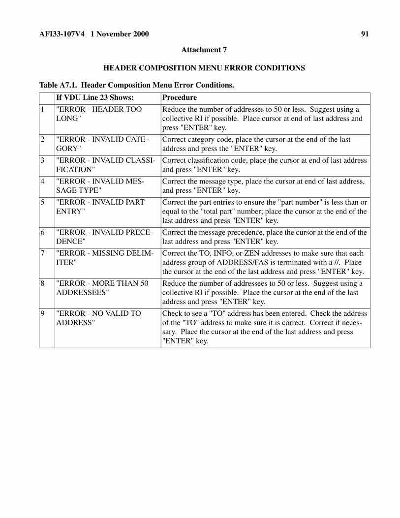
AFI33-107V4 1 November 2000 91
Attachment 7
HEADER COMPOSITION MENU ERROR CONDITIONS
Table A7.1. Header Composition Menu Error Conditions.
If VDU Line 23 Shows: Procedure
1 "ERROR - HEADER TOO LONG"
Reduce the number of addresses to 50 or less. Suggest using a collective RI if possible. Place cursor at end of last address and press "ENTER" key.
2 "ERROR - INVALID CATE-GORY"
Correct category code, place the cursor at the end of the last address and press the "ENTER" key.
3 "ERROR - INVALID CLASSI-FICATION"
Correct classification code, place the cursor at end of last address and press "ENTER" key.
4 "ERROR - INVALID MES-SAGE TYPE"
Correct the message type, place the cursor at end of last address, and press "ENTER" key.
5 "ERROR - INVALID PART ENTRY"
Correct the part entries to ensure the "part number" is less than or equal to the "total part" number; place the cursor at the end of the last address and press "ENTER" key.
6 "ERROR - INVALID PRECE-DENCE"
Correct the message precedence, place the cursor at the end of the last address and press "ENTER" key.
7 "ERROR - MISSING DELIM-ITER"
Correct the TO, INFO, or ZEN addresses to make sure that each address group of ADDRESS/FAS is terminated with a //. Place the cursor at the end of the last address and press "ENTER" key.
8 "ERROR - MORE THAN 50 ADDRESSEES"
Reduce the number of addressees to 50 or less. Suggest using a collective RI if possible. Place the cursor at the end of the last address and press "ENTER" key.
9 "ERROR - NO VALID TO ADDRESS"
Check to see a "TO" address has been entered. Check the address of the "TO" address to make sure it is correct. Correct if neces-sary. Place the cursor at the end of the last address and press "ENTER" key.

92 AFI33-107V4 1 November 2000
Attachment 8
FREE FORM MESSAGE COMPOSITION
Table A8.1. Free Form Message Composition.
Step Procedure Restrictions/Results
1 Establish session security level. Master Menu is displayed
2 Press "MEM CLR" key. Screen is blank. VDU line 23 shows "MEM CLR ENTER MESSAGE".
3 Press "SOH" key. Optional entry. SOH character shown as an inverted "L" character.
4 Type in classification code and a "/." Classification must match VDU line 21
5 Type in category code and a "/." Category must match VDU line 21.
6 Type in the two-character message type.
Reference USSTRATCOM Directive 501-14 (S) for legal message types.
7 Press "RETURN" key.
8 Type in message precedence. Legal precedence = Z, O, P, R.
9 Enter TO/INFO/ZEN addresses as follows:
No more than 50 total.
a. Press "TO" key. Must use TO key. "TO" is displayed.
b. Type in address (e.g., SAC01, ASI41).
Address is displayed.
c. If FAS required, enter slash (/) and FAS designator. If FAS is not required, go to Step 9d.
The capability is available to provide a unique FAS with each SACCS address.
d. Follow address or FAS with two slashes (//).
Two slashes must follow each address group. The address may consist of two parts: a primary address and a secondary address. The secondary address is omissible. The primary and secondary addresses are separated by a slash (/). Each address group is terminated with two slashes.
e. If more "TO" addresses are needed, repeat Steps 9b and 9c as needed.
f. Press "RETURN" key.
g. If INFO addresses required, Press "INFO" key.
"INFO" is displayed.
h. Repeat Steps 9b and 9d as needed for INFO addresses.
Address is displayed.
i. If ZEN addresses required, press "ZEN" key.
"ZEN" is displayed.

AFI33-107V4 1 November 2000 93
j. Repeat Steps 9b and 9d as needed for ZEN addresses.
Address is displayed.
10 If message is multiple parts, continue. If not, go to Step 11.
a. Press "RETURN" key.
b. Press "N/M" key.
c. Type in the word “PART” followed by a space, followed by a two-digit number, a slash (/), followed by a two-digit number.
First number must be equal to or smaller than second num-ber. Examples: Part 01/01, Part 01/02.
11 Press "STX" key. STX key required. STX character is shown.
12 Type in message text.
13 At end of text, press the “ETX” key. Text or ETX cannot exceed line 51. ETX character is shown.
14 Review and edit message. CAUTION! The TO, INFO, ZEN, and N/M key entries cause special codes to be entered in the message composi-tion buffer, but are displayed as blanks. For example, the blank before the word "INFO" is not a space, but a special key code. If you deleted "INFO" and all characters that fol-lowed, but did not delete the blank before "INFO" the soft-ware rejects the message for an address error when you try to transmit.
15 The message is ready to send, print, or store.
Step Procedure Restrictions/Results
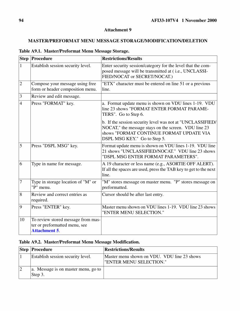
94 AFI33-107V4 1 November 2000
Attachment 9
MASTER/PREFORMAT MENU MESSAGE STORAGE/MODIFICATION/DELETION
Table A9.1. Master/Preformat Menu Message Storage.
Table A9.2. Master/Preformat Menu Message Modification.
Step Procedure Restrictions/Results
1 Establish session security level. Enter security session/category for the level that the com-posed message will be transmitted at ( i.e., UNCLASSI-FIED/NOCAT or SECRET/NOCAT.)
2 Compose your message using free form or header composition menu.
"ETX" character must be entered on line 51 or a previous line.
3 Review and edit message.
4 Press "FORMAT" key. a. Format update menu is shown on VDU lines 1-19. VDU line 23 shows "FORMAT ENTER FORMAT PARAME-TERS". Go to Step 6.
b. If the session security level was not at "UNCLASSIFIED/NOCAT," the message stays on the screen. VDU line 23 shows "FORMAT CONTINUE FORMAT UPDATE VIA DSPL MSG KEY." Go to Step 5.
5 Press "DSPL MSG" key. Format update menu is shown on VDU lines 1-19. VDU line 21 shows "UNCLASSIFIED/NOCAT." VDU line 23 shows "DSPL MSG ENTER FORMAT PARAMETERS".
6 Type in name for message. A 19 character or less name (e.g., ASORTIE OFF ALERT). If all the spaces are used, press the TAB key to get to the next line.
7 Type in storage location of "M" or "P" menu.
"M" stores message on master menu. "P" stores message on preformatted.
8 Review and correct entries as required.
Cursor should be after last entry.
9 Press "ENTER" key. Master menu shown on VDU lines 1-19. VDU line 23 shows "ENTER MENU SELECTION."
10 To review stored message from mas-ter or preformatted menu, see Attachment 5.
Step Procedure Restrictions/Results
1 Establish session security level. Master menu shown on VDU. VDU line 23 shows "ENTER MENU SELECTION."
2 a. Message is on master menu, go to Step 3.

AFI33-107V4 1 November 2000 95
Table A9.3. Master/Preformat Menu Message Deletion.
b. Message is on Preformatted menu, type in "04" and press "ENTER" key.
Preformat menu shown on VDU. VDU line 23 shows "ENTER MENU SELECTION". Go to Step 3.
3 Enter the menu number of message to be changed and the letter "M" (e.g., 08M).
4 Press "ENTER" key. a. Message shown on VDU. VDU line 23 shows "ENTER MODIFY MESSAGE - MSU/FORMAT KEY STORES, MENU KEY QUITS." Go to Step 6.b. Master or prefor-matted menu stays on screen. VDU line 23 shows "ENTER - PREFORMAT REQUEST INACCESSIBLE - CHECK DISPLAY MSG QUEUE." Go to Step 5.
5 Press "DSPL MSG" key. Message shown on VDU. VDU line 21, session security level is changed to match the message classification. VDU line 23 shows DSPL MSG - MODIFY MESSAGE - MSU/FORMAT KEY STORES, MENU KEY QUITS."
6 Make changes to message. "MENU" key.
ETX must be on line 51 or a previous line. To get out of modification mode (to quit at any time) press clear level (CLR LVL).
7 To restore message, continue.
8 Press "FORMAT" key. Modified message stays on screen. VDU line 23 shows "FORMAT – MESSAGE MODIFIED."
9 Review modified message on the master or preformatted menu. See Attachment 5.
Step Procedure Restrictions/Results
1 Press "CLR LVL" key. Session security menu is displayed.
2 Establish "UNCLASSIFIED/NOCAT" session security level.
Master menu is shown on screen.
3 a. If the message to be deleted is on the master menu, go to Step 4.
b. If the message to be deleted is on the Preformatted menu, Type in "04" and press "ENTER" key.
Preformat menu is shown on screen. VDU line 23 shows "ENTER MENU SELECTION."
4 Type in menu number of message to be deleted and the letter "D" (e.g., 08D).
Master menu is shown on screen. VDU line 23 shows "ENTER MENU SELECTION."
5 Press "ENTER" key.
Step Procedure Restrictions/Results

96 AFI33-107V4 1 November 2000
6 Request message from master or preformatted menu to make sure message was deleted.
Step Procedure Restrictions/Results

AFI33-107V4 1 November 2000 97
Attachment 10
MASTER/PREFORMAT MENU MESSAGE ERROR CONDITIONS
Table A10.1. Master/Preformat Menu Message Error Conditions.
Step If VDU Line 23 Shows: Procedure
1 "FORMAT ERROR - UNABLE TO ACCESS SECONDARY STORAGE."
a. Check master/preformatted menu to see if all menu num-bers are used. If all are used, you may have to store message on MSU file. Go to Attachment 11 for MSU storage.
b. Check status of device and media by entering a CATALOG command for the device containing the MENU diskette. If okay, retry menu selection. If problem, replace diskette/call maintenance as applicable.
c. Check AWCP/MUTE MSU 02 or BCP MSU 12 to see if MSU door is closed and MSU "READY" light is on.
2 "FORMAT ERROR -UNABLE TO ACCESS SECONDARY STOR-AGE (TOC FULL)."
The table of contents is full. Replace MENU diskette with another MENU diskette. Do not IPL.
3 "FORMAT ERROR - UNABLE TO ACCESS SECONDARY STORAGE (DISK FULL)."
The disk is full. Replace MENU diskette with another MENU diskette. Do not IPL.
4 "FORMAT ERROR - UNABLE TO ACCESS STORAGE (MEM-BER LIST FULL)."
The member list is full. Verify only one MENU diskette available to processor through the use of the CATALOG com-mand. Remove extra MENU diskette. If only one MENU diskette available, replace it with another MENU diskette. Do not IPL.
5 "FORMAT ERROR - UNABLE TO ACCESS SECONDARY STORAGE (I/O ERROR)."
Bad media, a missing disk, or a controller error.
6 "FORMAT ERROR - INVALID MENU SELECTION."
Check master or preformatted number selected and correct.
7 "ERROR - SESSION MUST BE AT UNCLASSIFIED/ NOCAT TO DELETE."
Do Steps 1-6 of the DELETE STORED MESSAGE proce-dure in Attachment 9, Table A9.3.
8 "ERROR - OPTION NOT R (RETRIEVE), M (MODIFY), or D (DELETE)"
Check option for R, M, or D. Reenter correct option and con-tinue.
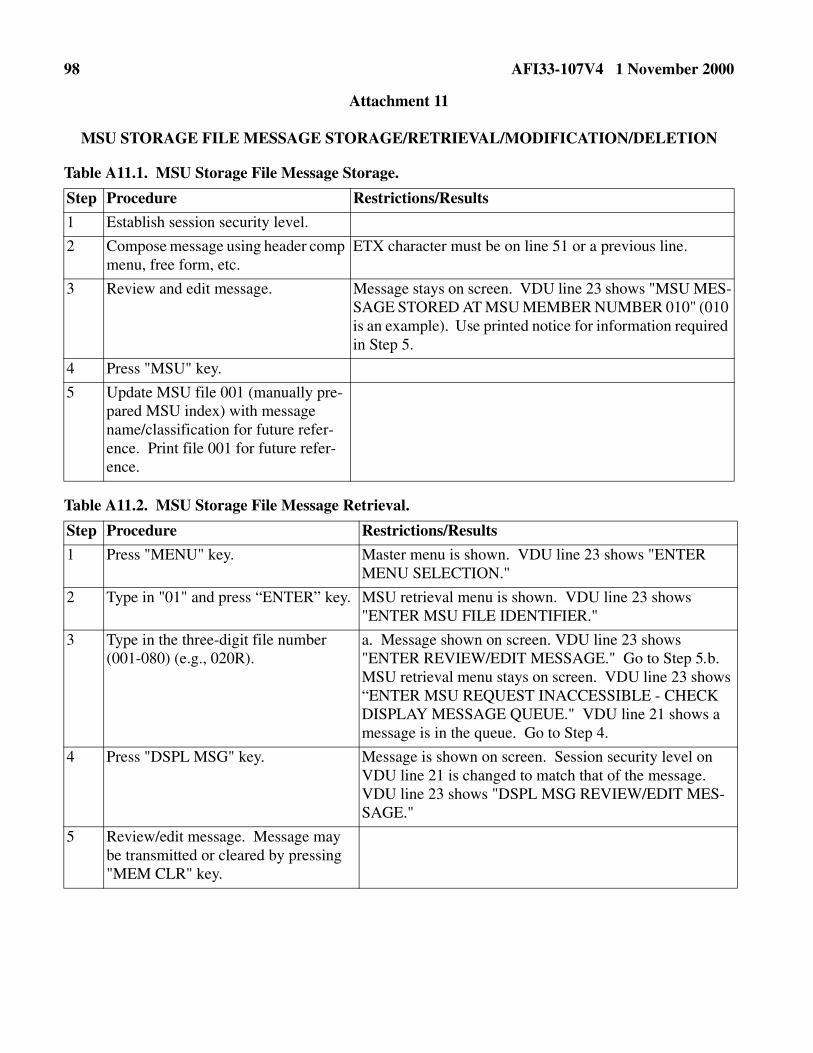
98 AFI33-107V4 1 November 2000
Attachment 11
MSU STORAGE FILE MESSAGE STORAGE/RETRIEVAL/MODIFICATION/DELETION
Table A11.1. MSU Storage File Message Storage.
Table A11.2. MSU Storage File Message Retrieval.
Step Procedure Restrictions/Results
1 Establish session security level.
2 Compose message using header comp menu, free form, etc.
ETX character must be on line 51 or a previous line.
3 Review and edit message. Message stays on screen. VDU line 23 shows "MSU MES-SAGE STORED AT MSU MEMBER NUMBER 010" (010 is an example). Use printed notice for information required in Step 5.
4 Press "MSU" key.
5 Update MSU file 001 (manually pre-pared MSU index) with message name/classification for future refer-ence. Print file 001 for future refer-ence.
Step Procedure Restrictions/Results
1 Press "MENU" key. Master menu is shown. VDU line 23 shows "ENTER MENU SELECTION."
2 Type in "01" and press “ENTER” key. MSU retrieval menu is shown. VDU line 23 shows "ENTER MSU FILE IDENTIFIER."
3 Type in the three-digit file number (001-080) (e.g., 020R).
a. Message shown on screen. VDU line 23 shows "ENTER REVIEW/EDIT MESSAGE." Go to Step 5.b. MSU retrieval menu stays on screen. VDU line 23 shows “ENTER MSU REQUEST INACCESSIBLE - CHECK DISPLAY MESSAGE QUEUE." VDU line 21 shows a message is in the queue. Go to Step 4.
4 Press "DSPL MSG" key. Message is shown on screen. Session security level on VDU line 21 is changed to match that of the message. VDU line 23 shows "DSPL MSG REVIEW/EDIT MES-SAGE."
5 Review/edit message. Message may be transmitted or cleared by pressing "MEM CLR" key.

AFI33-107V4 1 November 2000 99
Table A11.3. MSU Storage File Message Modification.
Table A11.4. MSU Storage File Message Deletion.
Step Procedure Restrictions/Results
1 Press "MENU" key. Master menu is shown. VDU line 23 shows "ENTER MENU SELECTION."
2 Type in "01R" and press” "ENTER" key.
MSU retrieval menu is shown. VDU line 23 shows "ENTER MSU FILE IDENTIFIER."
3 Type in the three-digit file number (001-080) to modify and the letter "M" (e.g., 020M).
4 Press "ENTER" key. a. Message shown on screen. VDU line 23 shows "ENTER MODIFY MESSAGE - MSU/FORMAT KEY STORES, MENU KEY QUITS." Go to Step 6.
b. MSU retrieval menu stays on screen. VDU line 23 shows "ENTER MSU REQUEST INACCESSIBLE - CHECK DISPLAY MESSAGE QUEUE". VDU line 21 shows that the display queue has incremented by 1. Go to Step 5.
5 Press "DSPL MSG" key. Message shown on VDU. VDU line 21, session security level is changed to match that of the message. VDU line 23 shows "DSPL MSG - MODIFY MESSAGE MSU/FORMAT KEY STORES, MENU KEY QUITS."
6 Make changes to message. ETX must be on line 51 or a previous line. To get out of modification mode (to quit at any time), press MENU key.
7 To restore message, continue.
8 Press "MSU" key. Modified message stays on screen. VDU line 23 shows "MSU - MESSAGE MODIFIED."
9 Go to Table A11.2. to view modified message.
Step Procedure Restrictions/Results
1 Press "MENU" key. Master menu is shown. VDU line 23 shows "ENTER MSU FILE IDENTIFIER."
2 Type in "01R" and press "ENTER" key.
MSU retrieval menu is shown. VDU line 23 shows "ENTER MSU FILE IDENTIFIER"
3 Type in the three-digit file number (002-080) to be deleted and the letter "D" (e.g., 030D).
4 Press "ENTER" key. MSU retrieval menu stays on screen. VDU line 23 shows MSU MESSAGE DELETED."

100 AFI33-107V4 1 November 2000
5 Update MSU file 001 to show that the file number has been deleted.
6 Press "MENU, "MEM CLR", or "CLR LVL" keys as required.
Step Procedure Restrictions/Results
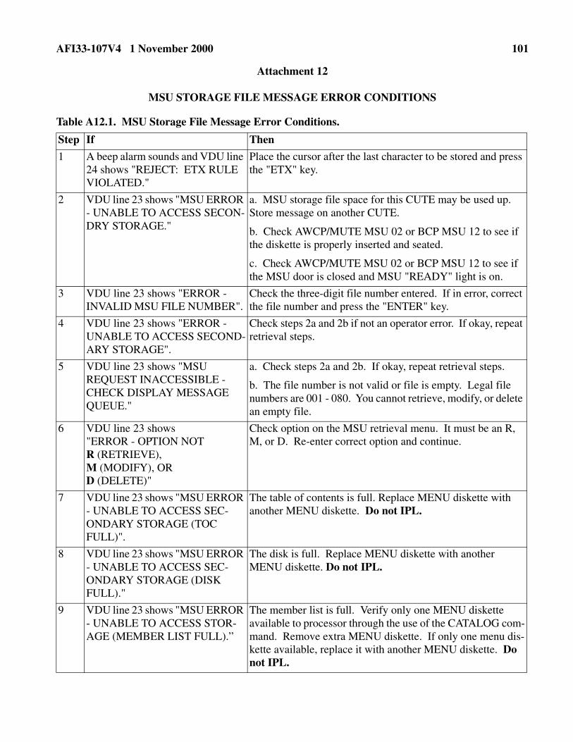
AFI33-107V4 1 November 2000 101
Attachment 12
MSU STORAGE FILE MESSAGE ERROR CONDITIONS
Table A12.1. MSU Storage File Message Error Conditions.
Step If Then
1 A beep alarm sounds and VDU line 24 shows "REJECT: ETX RULE VIOLATED."
Place the cursor after the last character to be stored and press the "ETX" key.
2 VDU line 23 shows "MSU ERROR - UNABLE TO ACCESS SECON-DRY STORAGE."
a. MSU storage file space for this CUTE may be used up. Store message on another CUTE.
b. Check AWCP/MUTE MSU 02 or BCP MSU 12 to see if the diskette is properly inserted and seated.
c. Check AWCP/MUTE MSU 02 or BCP MSU 12 to see if the MSU door is closed and MSU "READY" light is on.
3 VDU line 23 shows "ERROR - INVALID MSU FILE NUMBER".
Check the three-digit file number entered. If in error, correct the file number and press the "ENTER" key.
4 VDU line 23 shows "ERROR - UNABLE TO ACCESS SECOND-ARY STORAGE".
Check steps 2a and 2b if not an operator error. If okay, repeat retrieval steps.
5 VDU line 23 shows "MSU REQUEST INACCESSIBLE - CHECK DISPLAY MESSAGE QUEUE."
a. Check steps 2a and 2b. If okay, repeat retrieval steps.
b. The file number is not valid or file is empty. Legal file numbers are 001 - 080. You cannot retrieve, modify, or delete an empty file.
6 VDU line 23 shows "ERROR - OPTION NOT R (RETRIEVE),M (MODIFY), OR D (DELETE)"
Check option on the MSU retrieval menu. It must be an R, M, or D. Re-enter correct option and continue.
7 VDU line 23 shows "MSU ERROR - UNABLE TO ACCESS SEC-ONDARY STORAGE (TOC FULL)".
The table of contents is full. Replace MENU diskette with another MENU diskette. Do not IPL.
8 VDU line 23 shows "MSU ERROR - UNABLE TO ACCESS SEC-ONDARY STORAGE (DISK FULL)."
The disk is full. Replace MENU diskette with another MENU diskette. Do not IPL.
9 VDU line 23 shows "MSU ERROR - UNABLE TO ACCESS STOR-AGE (MEMBER LIST FULL).”
The member list is full. Verify only one MENU diskette available to processor through the use of the CATALOG com-mand. Remove extra MENU diskette. If only one menu dis-kette available, replace it with another MENU diskette. Do not IPL.

102 AFI33-107V4 1 November 2000
10 VDU line 23 shows "MSU ERROR - UNABLE TO ACCESS SEC-ONDARY STORAGE (I/O ERROR)."
Bad media, a missing disk, or a controller error.
Step If Then

AFI33-107V4 1 November 2000 103
Attachment 13
MESSAGE TRANSMISSION
Table A13.1. MessageTransmission.
Step Procedure Restrictions/Results
1 Press "XMT" button. XMT switch light comes on, then goes out. VDU line 22 shows "MESSAGE TRANSMITTED: #NNNN DDHHMMZMMM" (#NNNN = message sequence number. The DTG is the same as in the FROM line of the transmitted message.) A come-back copy of the message is printed on the LPU. The OPR ACK switch is lighted. An ETX character must be in the message.
2 Press the "OPR ACK" switch. VDU line 22 is blanked and the OPR ACK switch lamp is turned off.

104 AFI33-107V4 1 November 2000
Attachment 14
MESSAGE TRANSMISSION ERROR CONDITIONS
Table A14.1. Message Transmission Error Conditions.
Step If Then
1 VDU line 23 shows "XMT ERROR -NO VALID TO ADDRESS".
Correct the address and press the "XMT" button.
2 VDU line 23 "XMT" "ERROR - MES-SAGE TOO LONG.”
Reduce the number of lines (usually one line) or break the message into LONG parts. Insert the part entries in the last line of the header followed by the STX character. Delete the text to be sent in the next message using the "DEL LINE" key. Make sure the ETX character is in the message and press the "XMT" button.
3 VDU line 23 shows "XMT" ERROR - MORE THAN 50 ADDRESSES."
Use group RI addresses to bring the address total to less than 50 addresses.
4 VDU line 23 shows "XMT ERROR - INVALID CLASSIFICATION."
Check the classification of the message and the classifi-cation on VDU line 21. Change the classification to match VDU line 21, or re-establish the session security level and retype message. Press "XMT" button to retransmit.
5 VDU line 23 shows "XMT ERROR - INVALID CATEGORY."
Check the category of the message with the category on VDU line 21. Change the category to match VDU line 21 or re-establish the session security level and retype message. Press "XMT" button to retransmit.
6 VDU line 23 shows "XMT ERROR - NO START OF TEXT."
Move the cursor to the position after the last character of the header. Press "STX" key to enter STX character and a subsequent blank line. If the ETX or any characters (except spaces) are in line 52, the entry will be rejected and requires reducing the message length (see Step 2). Press "XMT" button to retransmit message.
7 VDU line 23 shows "XMT ERROR - CLASSIFICATION SESSION MIS-MATCH."
Re-establish session security level and retype message. Press "XMT" button to retransmit message.
8 VDU line 23 shows "XMT ERROR - CATEGORY/ SESSION MISMATCH."
Re-establish session security level and retype message. Press "XMT" button to retransmit message.
9 VDU line 23 shows "XMT ERROR - INVALID MESSAGE TYPE."
Change the message type. Press "XMT" button to retransmit message.
10 VDU line 23 shows "XMT ERROR - INVALID PRECEDENCE."
Change the message precedence to Z, O, P, or R. Press "XMT" button to retransmit message.

AFI33-107V4 1 November 2000 105
11 VDU line 23 shows "XMT ERROR - INVALID PART ENTRY."
Check the two-digit part number. It must be less than or equal to the second part number. Press the "XMT" but-ton to retransmit message.
12 VDU line 23 shows "XMT ERROR - MISSING DELIMITER."
Two slashes "//" must follow each address group (pri-mary/secondary) RI within the TO, INFO, and ZEN address header.
13 VDU line 22 shows "PRINTER FAIL-URE NO COMEBACK COPY: #NNNN DDHHMMZ MMM."
Record the message number (#NNNN) and the DTG. When the printer is operating, request a retrieval of the message (Attachment 19). Message was transmitted. Press OPR ACK button to blank VDU line 22 and shut off OPR ACK lamp.
14 VDU line 22 shows "TRANS-MISSION UNSUCCESSFUL, DEPRESS DSPL MSG KEY".
Check Attachment 16 for error/rejection reasons. Press button to blank VDU line 22 and OPR ACK and shut off OPR ACK lamp.
15 VDU line 22 displays "MESSAGE RECEIVED FROM (OSRI): MES-SAGE #NNNN DDHHMMZ MMM" and the LPU prints one of the following service messages:
a. "THE FOLLOWING DESTINA-TIONS DID NOT RECEIVE YOUR MESSAGE #NNNN: XXXXX, XXXXX" XXXXX = address).
a. Retransmit message to addresses that did not get the message due to being down.
b. "YOUR MESSAGE #NNNN NOT DELIVERED TO XXXXX: THE ERROR IS AUTHORIZED DESTINA-TION."
b. The address is not allowed to receive the message because the classification level exceeds that of the desti-nation. Message was transmitted to all other addresses.
c. "YOUR MESSAGE #NNNN NOT DELIVERED TO XXXX: THE ERROR IS INVALID MESSAGE TYPE."
c. The address is not allowed to receive that type of traf-fic (e.g., XX, AU, JJ). Message was transmitted to all other addresses if there were other addresses in the mes-sage.
d. "YOUR MESSAGE "NNNN NOT DELIVERED TO XXXXX: THE ERROR IS ILLEGAL MESSAGE TYPE."
e. "YOUR MESSAGE #NNNN NOT DELIVERED TO XXXXX: THE ERROR IS SECURITY FIELD MIS-MATCH."
Step If Then

106 AFI33-107V4 1 November 2000
Attachment 15
PRINTING VDU SCREEN CONTENTS
Table A15.1. Printing VDU Screen Contents.
Step Procedure Restrictions/Results
1 Press the "PRINT" key. Message on VDU lines 1-19 remains unchanged. VDU line 23 shows "PRNT PRINT REQUESTED." Message from VDU prints on LPU with security banners same as VDU line 21. OPR ACK lamp lights.
2 If a beep alarm sounds and VDU line 24 shows REJECT: ETX RULE VIO-LATED."
Place the cursor after the last character to be printed and press the ETX key. Press "PRINT" key again.
3 If VDU line 23 shows "PRNT PRINT REQUESTED" and after a short delay, VDU line 22 shows one of the following:
a. "PRINT REJECTED - PRINTER DOWN."
a. Check status of LPU and bring on-line.
b. "PRINT REJECTED - PRINTER OFF-LINE."
b. Press "ON LINE/OFF LINE" button on LPU to bring printer on-line.
c. "PRINT REJECTED - PRINTER PAPER ALARM."
c. Check printer. Paper is jammed or out of paper. To change LPU paper, see Attachment 3.
4 Press OPR ACK button. OPR ACK lamp goes out.

AFI33-107V4 1 November 2000 107
Attachment 16
DISPLAY MESSAGES (REQUIRES DEPRESSING "DSPL MSG" KEY)
Table A16.1. Display Messages.
Step If VDU Line 23 Shows: Procedure
1 "DSPL MSG ENTER FORMAT PARAMETERS."
The session security level must be in the UNCLASSIFIED/NOCAT level in order to update master or preformatted menu screens. See Table A9.1.
2 "DSPL MSG REVIEW/EDIT MES-SAGE."
Requested format was stored at a higher security level than the existing session security level. The session security level is changed to match that of the message.
3 "DSPL MSG MESSAGE DELIV-ERY NOT VERIFIED RE-TRANS-MIT."
Message delivery not known. Retransmit message.
4 "DSPL MSG MESSAGE REJECTED - ILLEGAL INPUT DEVICE."
Transmission rejected. Correct message as required and retransmit.
5 "DSPL MSG MESSAGE REJECTED - INVALID PRECE-DENCE."
Transmission rejected. Correct the precedence and retrans-mit.
6 "DSPL MSG MESSAGE REJECTED - INVALID MESSAGE TYPE."
Transmission rejected. Correct the message type and retransmit.
7 "DSPL MSG MESSAGE REJECTED - FIELD MISMATCH: RETRANSMIT."
Transmission rejected. Retransmit message as is.
8 "DSPL MSG MESSAGE REJECTED - ILLEGAL PRECE-DENCE LEVEL".
Message precedence not allowed from this CUTE. Lower the precedence, if possible, and retransmit.
9 "DSPL MSG MESSAGE REJECTED - ILLEGAL MES-SAGE TYPE."
Transmission rejected. Correct the message type and retransmit.
10 "DSPL MSG MESSAGE REJECTED - MULTIPLE ERRORS: SEE PRINTER."
Transmission rejected. See LPU for errors. Correct the errors identified and retransmit.
11 "DSPL MSG MESSAGE REJECTED - NO VALID TO ADDRESS."
Transmission rejected. Correct the TO address and REJECTED - VALID retransmit.
12 "DSPL ERROR - INVALID CLAS-SIFICATION".
Transmission rejected. Correct the classification and retransmit.

108 AFI33-107V4 1 November 2000
13 "DSPL MSG ERROR - INVALID CATEGORY."
Transmission rejected. Correct the category and retransmit.
14 "DSPL MSG DEPRESS EAM ACK AND MSU KEY."
An EAM could not be printed because the LPU was down. ACK the EAM and store the message on the MSU by press-ing the MSU key. Later, when the LPU is up, recall the mes-sage and print it for a hard copy.
Step If VDU Line 23 Shows: Procedure

AFI33-107V4 1 November 2000 109
Attachment 17
MESSAGE RECEPTION
Table A17.1. Non-EAM Message Receipt.
Table A17.2. Alternate Destination Initiated--Message Received.
Table A17.3. Alternate Destination Terminated.
Table A17.4. EAM Message Reception.
Step Procedure Restrictions/Results
1 Non-EAM message received. VDU line 22 shows " MESSAGE RECEIVED FROM (OSRI): MESSAGE #NNNN DDHHMMZ MMM." The OPR ACK lamp is lighted. The message prints on the LPU.
2 Press the "OPR ACK" button. VDU line 22 is blanked and the OPR ACK light goes out.
Step Procedure Restrictions/Results
1 Alternate destination initiated automatically for CUTE failure. Messages for the failed CUTE, printed at this alternate CUTE.
VDU line 22 shows "XXXXXXX IS NOW RECEIVING TRAFFIC AS ALTERNATE FOR XXXXXXX." The OPR ACK lamp is lighted. The message prints on LPU with the routing identifier of the primary address and an "N" in the last field of the FROM line. Subsequent messages for the failed RI may be received by this CUTE until the failed CUTE is back on line.
2 Press the "OPR ACK" button. VDU line 22 is blanked and the OPR ACK light goes out.
Step Procedure Restrictions/Results
1 Alternate destination terminated automatically when the failed CUTE becomes operational.
VDU line 22 shows "XXXXXXX IS NO LONGER RECEIV-ING TRAFFIC AS ALTERNATE FOR XXXXXXX." The OPR ACK lamp is lighted. No more messages for the failed RI are printed by this CUTE unless the notice for alternate initia-tion is received again.
2 Press the "OPR ACK" button. VDU line 22 is blanked and the OPR ACK light goes out.
Step Procedure Restrictions/Results
1 EAM message received. VDU line 22 shows "MESSAGE RECEIVED FROM (OSRI): MESSAGE #NNNN DDHHMMZ MMM." The OPR ACK lamp lights. The EAM ACK lamp lights and blinks. The alarm sounds. Two copies of EAM print on LPU.
2 Press "OPR ACK" button. Alarm is silenced. EAM ACK light remains lit.
3 Review message for validity as per HQ ACC/HQ STRATCOM regulations.

110 AFI33-107V4 1 November 2000
4 Press "EAM ACK" button. EAM ACK light goes out. EAM ACK message is transmitted to EAM originator.
5 Press "OPR ACK" button. VDU line 22 is blanked and the OPR ACK lamp goes out.
Step Procedure Restrictions/Results

AFI33-107V4 1 November 2000 111
Attachment 18
MESSAGE RECEPTION ERROR CONDITIONS
Table A18.1. Message Reception Error Conditions.
Note If VDU Line 22 Shows "PRINT FAILURE" Then
1 NON-EAM MESSAGES:
a. "PRINT FAILURE - PAPER ALARM: RETRIEVE MESSAGE #NNNN OSRI=XXXXX."
a. For VDU line 22 notices "PRINT FAILURE" 1a through 1d, retrieve the message when the printer becomes operational.
b. "PRINT FAILURE - PRINTER OFF-LINE: RETRIEVE MESSAGE #NNNN OSRI=XXXXX."
c. "PRINT FAILURE - PRINT QUEUE FULL: RETRIEVE MESSAGE #NNNN OSRI=XXXXX."
d. "PRINT FAILURE - PRINTER DOWN: RETRIEVE MESSAGE #NNNN OSRI=XXXXX."
e. "PRINT FAILURE - SECURITY VIOLA-TION: MESSAGE #NNNN OSRI=XXXXX."
e. This error condition indicates a message with a higher classification than is allowed was sent to this destination and cannot be retried.
2 EAM MESSAGES: If the printers are down and an EAM is received, the display message queue will be incremented by one. The OPR ACK light will come on and the EAM ACK light and alarm will come on. One of the fol-lowing VDU line 22 notices should appear if both printers are down:
a. "PRINT FAILURE - PAPER ALARM: DEPRESS DSPL MSG. KEY FOR MSG #NNNN."
b. "PRINT FAILURE - PRINTER OFF-LINE: DEPRESS DSPL MSG KEY FOR MSG #NNNN."
c. "PRINT FAILURE - PRINT QUEUE FULL: DEPRESS DSPL MSG KEY FOR MSG #NNNN."
d. “PRINT FAILURE - PRINTER DOWN: DEPRESS DSPL MSG KEY FOR MSG #NNNN."
When any "PRINT FAILURE" notices occur, press the "DSPL MSG" key to view and validate the EAM. If required, transcribe the EAM from the VDU to the EAM copy format. Also, press the "MSU" key to store the EAM for retrieval and printing when the printers become opera-tional.

112 AFI33-107V4 1 November 2000
Attachment 19
MESSAGE RETRIEVAL
Table A19.1. Message Retrieval.
Step Procedure Restrictions/Results
1 Press "CLR LVL" key. Security Menu is shown.
2 Press the "TAB" key. Cursor is placed on VDU line 19, column 1.
3 TYPE IN:
a. The word "RET." a. Required entry.
b. A space. b. Required entry.
c. The routing indicator of the accountable processor.
c. Required entry.
d. A comma. d. Required entry.
e. The OSRI. e. Optional entry. This could be your own CUTEs RI or the RI of another CUTE that sent messages. OSRI is one address. Retrieval cannot use a group RI.
f. A comma. f. Required entry.
g. The DSRI. g. Optional entry. This could be your own CUTEs RI if messages were those addressed to your CUTEs or the desti-nation RI of messages transmitted by your CUTEs. DSRI is one address. Retrieval cannot use a group RI.
h. A comma. h. Required entry.
i. The MSN NNNN. i. Optional entry. Four-digit message number of the specific message.
j. A comma. j. Required entry.
j. Required entry. k. Optional entry. Speeds up retrieval request.
4 A comma. Required entry if retrieving to the VDU.
5 VDU Optional entry.
6 Review command. Separate multiple entries with a "/."

AFI33-107V4 1 November 2000 113
7 Press "ENTER" key. RETRIEVAL OF MESSAGES MAY BE DELAYED BECAUSE THE OPERATOR AT THE SCP/BCP MAY HAVE TO MOUNT JOURNAL DISKETTES FROM STORAGE FILES.
a. LPU prints DTG and an echo of the command as entered.
b. VDU line 22 shows "YOUR RETRIEVAL REQUEST ACCEPTED FOR PROCESSING AS: MSN NNNN DTG DDHHMMZ MMM.
c. VDU line 22 shows "MESSAGE RECEIVED FROM (OSRI): MESSAGE #NNNN DDHHMMZ MMM" as each retrieved message is printed on the LPU, if any are retrieved. Retrieved messages can be identified having a line of dashes on the LPU copy.
d. VDU line 22 shows "YOUR RETRIEVAL REQUEST: #NNNN DDHHMMZ MMM COMPLETED AT DDH-HMMZ MMM." This means all messages were retrieved. See paragraph 3.13.2. for additional information.
e. If no messages were available for retrieval, VDU line 22 will show "YOUR RETRIEVAL REQUEST: #nnnn DDH-HMMZ MMM: NO MESSAGES RECEIVED."
8 Press "OPR ACK" button as many times as needed to blank VDU line 22 and extinguish OPR ACK lamp.
9 If the DTG in the service message in Step 5d is not the same as stop DTG in the retrieval request and further retrieval is desired, enter a second retrieval request with the same inputs as the original, except change the start DTG to that shown on the service message in Step 5d.
Step Procedure Restrictions/Results

114 AFI33-107V4 1 November 2000
Attachment 20
OPERATOR COMMANDS (USING A CUTE)
Table A20.1. Set Device Status.
Table A20.2. Set Line Status.
NOTE: An UP/DN action parameter is required to take a printer or VDU offline. All commands are entered having the session security level menu on the VDU and the cursor on display line 19, column 1.
Step Procedure Restrictions/Results
1 Type "DEVICE" or "DEV"
2 A space.
3 Physical device ID (NN or NNN).
NN = two digit number (01-02) for the LPU.
NNN = three digit number (100 plus the device identifier 01-02) for the VDU/KB.
4 A comma.
5 Enter status "UP or DN." EXAMPLE: DEV 01,UP
DEV 102,DN
6 Press "ENTER" key. Date-time-group is printed, followed by the command.
7 Response message prints on LPU.
"DDHHMMZ LPU 01 UP"
"DDHHMMZ VDU 02 DN - OPERATOR REPORTED FAIL-URE."
NOTE: All commands are entered having the session security level menu on the VDU and the cur-sor on display line 19, column 1.
Step Procedure Restrictions/Results
1 Type "LINE" or "LIN".
2 A space.
3 Line ID. One or more entries (NN).
NN = 01-32.
4 A comma.
5 Enter change of status line. EXAMPLE: LIN 11,UP
LIN 11,DN
6 Press "Enter" key. Date-time-group is printed, followed by the command.
7 Response message prints on LPU.
"DDHHMMZ SACCS LINE 11 IS UP"
DDHHMMZ SACCS LINE 11 IS DOWN. OPERATOR REPORTED FAILURE."

AFI33-107V4 1 November 2000 115
Table A20.3. Set Date-Time.
Table A20.4. Set Alternate Destination.
NOTE: This is to change system date and time without an IPL. All commands are entered having the session security level menu on the VDU and the cursor on display line 19, column 1.
Step Procedure Restrictions/Results
1 Type "DTG".
2 A space.
3 Date time
(DDHHMMZ MMM YY).
EXAMPLE: DD = Day of Month
HH = Hour
MM = Month
YY = Year
DTG 261230Z APR 99
4 Press "ENTER" key. Date-time-group is printed, followed by the command.
5 Response message prints on LPU.
"DDHHMMZ DATE-TIME SET"
"DDHHMMZ UNABLE TO SET DATE-TIME"
(If this occurs, re-enter command.)
NOTE: This makes an alternate CUTE to receive traffic. All commands are entered having the session security level menu on the VDU and the cursor on display line 19, column 1.
Step Procedure Restrictions/Results
1 Type "ALTERNATE" or "ALT."
2 A space.
3 RI of primary CUTE, a (/) and the RI of alternate desired.
EXAMPLE: ALT ELL00/ELL01
4 Press "ENTER" key. Date-time-group is printed, followed by the command.
5 Response message prints on LPU.
"DDHHMMZ ALTERNATE DESTINATION ASSIGNMENT. PRIMARY UTE AAAA AND ALTERNATE UTE BBBB IS XX."
(XX = ACCEPTED/REJECTED)

116 AFI33-107V4 1 November 2000
Table A20.5. Table Printout.
Table A20.6. Retrieve Messages.
Table A20.7. Toggle X-Precedence Journaling (at BCP).
NOTE: These are the procedures to print line, equipment, processor status, and destination rout-ing table at LPU [device 01] default. All commands are entered having the session security level menu on the VDU and the cursor on display line 19, column 1.
Step Procedure Restrictions/Results
1 Type "TABLE" or "TAB".
2 A space.
3 Table ID. Output will be all tables if non-specified.
EXAMPLE: TAB LST
TABLE EST, LST
EST (Equipment Status Table)
LST (Line Status Table)
PST (Processor Status Table)
DRT
4 Press "ENTER" key. Date-time-group is printed, followed by the command.
NOTE: All commands are entered having the session security level menu on the VDU and the cur-sor on display line 19, column 1.
Step Procedure Restrictions/Results
1 Type in "RETRIEVE" or "RET." Recall journaled messages from BCP or SCP.
2 Type in necessary parameters. Enter parameters according to the description in paragraph 3.13.
3 Press "ENTER" key.
NOTE: All commands are entered having the session security level menu on the VDU and the cur-sor on display line 19, column 1.
Step Procedure Restrictions/Results
1 Type in "TOGGLE" or "TOG." Starts or stops journaling of system control messages. Default of command at IPL is "OFF." Applicable to BCPs only.
2 A space.
3 Toggle status of "ON" or "OFF."
4 Press "ENTER" key. Date-time-group is printed, followed by command. "DDH-HMMZ TOG ON" or "DDHHMMZ TOG OFF"

AFI33-107V4 1 November 2000 117
Table A20.8. Reset SFU Lights.
Table A20.9. Identify Operator Stations.
Table A20.10. Catalog Diskette Directories.
NOTE: All commands are entered having the session security level menu on the VDU and the cur-sor on display line 19, column 1.
Step Procedure Restrictions/Results
1 Type in "SFU".
2 Press "ENTER" key. Date-time-group is printed followed by command. Turns Sum-mary Fault Unit lights off.
NOTE: All commands are entered having the session security level menu on the VDU and the cur-sor on display line 19, column 1.
Step Procedure Restrictions/Results
1 Type in "SWITCH" OR "SWI." Assigns switch operator functions to a CUTE. Entered at the new CUTE SWOP.
2 Press "ENTER" key. DTG is printed followed by command. "DDHHMMZ CEASE SWITCH FUNCTIONS" (at old operator station location) and "DDHHMMZ ASSUME SWITCH FUNCTIONS" (at new SWOP location).
NOTE: At the BCP, commands may be entered at the KSR43 or VDU, depending on which device is to become active. At the BCP, the command "SWITCH" or "SWI" must be entered at the CUTE assuming the SWOP function from the KSR-43. When assigning the operator function back to the KSR-43, the command is entered on the KSR-43.
NOTE: All commands are entered having the session security level menu on the VDU and the cur-sor on display line 19, column 1.
Step Procedure Restrictions/Results
1 Type in "CATALOG" or "CAT." Catalogs the directory information of each diskette without having to open and close the MSU door.
2 Type in parameters. Enter parameters according to paragraph 4.13.
3 Press "ENTER" key. DTG is printed followed by command. Another line consisting of DTG, the device ID, and the volume name or title of the dis-kette is printed.

118 AFI33-107V4 1 November 2000
Table A20.11. Copy Menu Diskettes.
Table A20.12. Print Crypto Status Report.
Table A20.13. Data Collection.
NOTE: All commands are entered having the session security level menu on the VDU and the cur-sor on display line 19, column 1.
Step Procedure Restrictions/Results
1 Type in "COPY" or "COP." Make a duplicate copy of existing MENU diskette. Perform procedures described in paragraph 4.12.
2 Press "ENTER key."
NOTE: All commands are entered having the session security level menu on the VDU and the cur-sor on display line 19, column 1.
Step Procedure Restrictions/Results
1 Type in "CRY". Produces a report at the SWOP showing the status of each line's crypto and when it was last updated automatically.
2 Press "ENTER" key. DTG is printed followed by the CSR report.
NOTE: All commands are entered having the session security level menu on the VDU and the cur-sor on display line 19, column 1.
Step Procedure Restrictions/Results
1 Type in "DATA" or "DAT." Allows the accumulation or distribution of information about processor resources at BCPs only. Implemented on request of the Offutt SACCS NQCC only.
2 A space.
3 Type in 1st parameter. "START," "STOP," or "SEND,"
4 A comma.
5 Type in 2nd parameter. "PROCESSOR," "DEVICE," "LINE," or "QUEUE,"
6 Press "ENTER" key. DTG is printed followed by the command.

AFI33-107V4 1 November 2000 119
Table A20.14. Deliver Messages (BCP SWOP Only).
Table A20.15. Log of System Performance.
Table A20.16. Long-Term Journal Closure.
NOTE: All commands are entered having the session security level menu on the VDU and the cur-sor on display line 19, column 1.
Step Procedure Restrictions/Results
1 Type in "DELIVER" or "DEL." Retrieves from BCP journal and retransmits messages identi-fied as NONDELIVERED messages for subscribers of the BCP.
2 Type in necessary parameters. Enter parameters according to the description in paragraph 3.14.
3 Press "ENTER" key. DTG is printed followed by command. Another line consisting of DTG, and the status of the delivery request is printed.
NOTE: All commands are entered having the session security level menu on the VDU and the cur-sor on display line 19, column 1.
Step Procedure Restrictions/Results
1 Type "LOG." This command starts or stops the journaling of system perfor-mance data. The information is stored on the journal diskette for subsequent analysis when invoked. Normally not logged unless requested by the SACCS NQCC. Not logging data sig-nificantly reduces the number of journal diskettes used.
2 A space.
3 Type in parameter of "START" or "STOP."
4 Press "ENTER" key.
NOTE: All commands are entered having the session security level menu on the VDU and the cur-sor on display line 19, column 1.
Step Procedure Restrictions/Results
1 Type "LTJ" and press "ENTER." This command closes the current journal diskette and forces the processor to use the space as the new current journal. The com-mand will cause a journal LABEL notice to be output to the SWOP and a request to mount a replacement journal.

120 AFI33-107V4 1 November 2000
Table A20.17. Purge of EPU File from Menu.
Table A20.18. Simulation Data File Initiation.
Table A20.19. Dump File Transmission.
NOTE: All commands are entered having the session security level menu on the VDU and the cur-sor on display line 19, column 1.
Step Procedure Restrictions/Results
1 Type "PURGE". The command is used to remove old data from a file on the MENU diskette that may contain programming code. This must only be used prior to receiving an Electronic Program Update from the Offutt CPMF.
2 Press "ENTER" key.
NOTE: All commands are entered having the session security level menu on the VDU and the cur-sor on display line 19, column 1.
Step Procedure Restrictions/Results
1 Type "SDF." Provides the capability to initiate simulated CUTE input from a prepared file on diskette. The Offutt CPMF must prepare the SDF for use at each processor.
2 A space.
3 Type in necessary parameters. These parameters are provided with the SDF diskette.
4 Press "ENTER" key.
NOTE: All commands are entered having the session security level menu on the VDU and the cursor on display line 19, column 1.
Step Procedure Restrictions/Results
1 Type in "DUMP" or “DUM” and press "ENTER" key.
Starts the process that allows the transmission of information contained on a DUMPFILE diskette to the CPMF at Offutt. DTG is printed followed by a command. Additional SWOP output consisting of a menu selection is also produced.n ddhhmmZ CHANGE 1 NO NAME CHANGE 2 DUMPFILE TO F0000030 3 F0000030 TO DUMPFILE 4 JOURNAL TO F0000030 5 F0000030 TO JOURNAL

AFI33-107V4 1 November 2000 121
Step Procedure Restrictions/Results
2 Type "n 2" and press "ENTER." The "n" represents the prompt number and "2" is the menu selection number to change the diskette volume name from DUMPFILE to F0000030. Only diskettes with a volume name of F0000030 can be transmitted to the Offutt CMPF.
The SWOP outputs a menu selection to identify the MSUs that are available to install the DUMPFILE diskette that is to be renamed.
n ddhhmmZ CHOOSE POSITION FOR DUMPFILE1 12 MENU (normally)2 24 EMPTY (normally)3 25 EMPTY (normally)
(Only devices that don't have locked files will be shown as available.)
3 Type "n 2" or "n 3" and press "ENTER."
The SWOP outputs the following notice:n ddhhmmz m DUMPFILE
4 Remove the diskette from the device identified in Step 3 above and replace it with the DUMP-FILE diskette that is to be changed to F0000030.
The Auto CATALOG feature causes the following output at the SWOP:
ddhhmmZ DEVICE nn CONTAINS DUMPFILE. NOTE: This DUMPFILE does not show as LOCKED and is, therefore, not the system DUMPFILE.
5 Type "1 YES" and press "ENTER."
This tells the processor that you have mounted the DUMPFILE diskette and that it can perform the name change action. After the name change is complete, the SWOP outputs the following menu.
n ddhhmmZ CHANGE
1 NO NAME CHANGE
2 DUMPFILE to F0000030
3 F0000030 TO DUMPFILE
4 JOURNAL TO F0000030
5 F0000030 TO JOURNAL
6 Type "1 1" and press “ENTER”. The SWOP outputs the following notice: END OF FILE NAME CHANGES. After the above notice, the SWOP outputs the following menu.
n ddhhmmZ CHOOSE POSITION TO MOUNT F0000030
1 12 MENU (normally)
2 24 EMPTY (normally)
3 25 EMPTY (normally)

122 AFI33-107V4 1 November 2000
Step Procedure Restrictions/Results
7 Type in same response used in Step 3.
The SWOP outputs the following notice: n ddhhmmZ M F0000030** MOUNT REMOTE DUMP DISKETTE
8 Open and close door on the device that contains F0000030.
Auto CATALOG will cause the following to be output at the SWOP: hhmmZ DEVICE nn CONTAINS F0000030.
9 Verify that the Offutt CPMF is ready to receive the REMOTE DUMP transmission.
If the Offutt CPMF is not ready, the next step will time out.
10 Enter "1 YES" and press “ENTER.”
The SWOP outputs the following notice if the CPMF is ready to receive the transmission: "DATA DUMP TRANSMISSION BEGINNING"
When the REMOTE DUMP is complete, the SWOP will print the following: "ddhhmmZ DATA DUMP PROCESSING COMPLETED; REASON: NORMAL COMPLETION"
11 Type in "DUMP" or “DUM” and press "ENTER" key.
The diskette with file name F000003 must be changed back to its original name. DTG is printed followed by command. An additional SWOP output consisting of a menu selection is also produced.
n ddhhmmZ CHANGE
1 NO NAME CHANGE
2 DUMPFILE to F0000030
3 F0000030 TO DUMPFILE
4 JOURNAL TO F0000030
5 F0000030 TO JOURNAL
12 Type "n 3" and press “ENTER” n represents the prompt number and 3 is the menu selection num-ber to change the diskette vol-ume name from F0000030 to DUMPFILE.
The SWOP will give you a menu selection to identify which MSUs are available to install the F0000030 diskette that is to be renamed.
n ddhhmmZ CHOOSE POSITION FOR DUMPFILE
1 12 MENU (normally)
2 24 EMPTY (normally)
3 25 F0000030 (file to change)
(Only devices not having locked files will be shown as avail-able.)
13 Type "n 3" and press “ENTER”. The SWOP outputs the following notice: n ddhhmmZ M F0000030.

AFI33-107V4 1 November 2000 123
Step Procedure Restrictions/Results
14 Type "1 YES" and press “ENTER.”
This tells the processor that the F0000030 diskette is available and that it can perform the name change action. After the name change is complete, the SWOP outputs the following menu.
n ddhhmmZ CHANGE
1 NO NAME CHANGE
2 DUMPFILE to F0000030
3 F0000030 TO DUMPFILE
4 JOURNAL TO F0000030
5 F0000030 TO JOURNAL
15 Type "1 1" and press “ENTER.” The SWOP prints the following notice:
END OF FILE NAME CHANGES. After the notice, the operator station outputs the following menu.
n ddhhmmZ CHOOSE POSITION TO MOUNT F0000030
1 12 MENU (normally)
2 24 EMPTY (normally)
3 25 EMPTY (normally)
16 Type "1 NO" and press “ENTER.”
The SWOP prints the following notice: DATA DUMP TERMI-NATED NO DISKETTE. This ends a complete REMOTE DUMP sequence.

124 AFI33-107V4 1 November 2000
Attachment 21
SYSTEM NOTIFICATION MESSAGES
Table A21.1. System Notification Messages.
Note Message. No Action Call Maint.
1 "CONTROLLER FAILURE. UNIT = CED-1. AFFECTED EQUIPMENT IS XXX." (XXX = LIN/VDU/PRT)
X
2 "DDHHMMZ ALTERNATE YYYYYYY XXX INITIATED FOR ZZZZZZZ." (XXX = WAS/NOT)
X
3 "DDHHMMZ COMMUNICATION LINE #NN NOT FOUND IN STATUS TABLE." (NN = line number)
X
4 "DDHHMMZ CONNECTIVITY TO THE PARENT SCP OR BCP HAS BEEN LOST. TAKE RECONFIGURATION ACTION."
X
5 "DDHHMMZ DELIVERY OF CONNECTIVITY STATUS MES-SAGE TO XXXXXXX WAS SUCCESSFUL."
X
6 "DDHHMMZ DELIVERY OF CONNECTIVITY STATUS MES-SAGE TO XXXXXXX WAS UNSUCCESSFUL. THERE IS CUR-RENTLY NO PATH TO THE PARENT ACCOUNTABLE PROCESSOR. PLEASE TAKE THE APPROPRIATE RECONFIG-URATION ACTION."
X
7 "DDHHMMZ I/O FAILURE FOR MSU NN. FAILED UNIT IS MSU." (NN = MSU position)
X
8 "DDHHMMZ I/O SUCCESSFUL FOR MSU NN." (NN = MSU position)
X
9 "DDHHMMZ LABEL XX MMDDHHMMZ - MMDDHHMMZ N DDHHMMZ M JOURNAL XX MOUNT NEW JOURNALING VOLUMES." (XX = MSU position: 22 or 23. N = 1, 2, or 3) (BCP Notice)
X
10 "DDHHMMZ LINE #NN IS DOWN DUE TO XX FAILURE." (XX = interface / crypto / modem / crc / resynchronization. NN = line number)
X
11 "DDHHMMZ LINE #NN IS UP."
(NN = line number)
X
12 "DDHHMMZ MESSAGE #NNNN OSRI = XXXXXXX NOT DELIVERED TO XXXXXXX."
Retransmit Message

AFI33-107V4 1 November 2000 125
13 "DDHHMMZ MSU XX MEDIA FAILURE: ISN=YY. CYCLE STEAL STATUS WORDS = CCCCCCCCCCCCCCCCCCCCC.
DDHHMMZ LABEL XX MMDDHHMZ - MMDDHHMMZ N DDHHMMZ M JOURNAL XX MOUNT NEW JOURNALING VOLUMES" (N = 1, 2, or 3) (XX = MSU position 22 or 23. CCC= CYCLE STEAL STATUS WORDS.) (BCP Notice)
X
14 "DDHHMMZ THR XXXX pp%" XXXX = INIT/TERM pp = per-cent
X
15 "DDHHMMZ PROCESSOR TEST FAILURE ERROR ID = EE." (EE = error code)
X
16 "DDHHMMZ PROCESSOR TEST SUCCESSFUL." X
17 "DDHHMMZ READING FAILURE FOR VDU NN. FAILED UNIT IS VDU."
X
18 "DDHHMMZ RESTART DUE TO ZZ XX." (ZZ = SVC ABORT / PROGRAM CHECK / SOFT EXCEPTION CHECK / PROCESS TIMEOUT / INVALID DEVICE. XX = FULL DUMP / PARTIAL DUMP / NO DUMP / IO ERROR DURING DUMP."
X
19 "DDHHMMZ SUSPECTED CHANNEL FAILURE. FAILED UNIT IS CED-1."
X
20 "DDHHMMZ TEST SUCCESSFUL FOR VDU NN." (NN = VDU number)
X
21 "DDHHMMZ THR XXXX PROCABC pp%" ABC = 3 character ID processor XXXX = INIT/TERM pp = percent.
X
22 "DDHHMMZ UNIT NOT READY MSU #XX." X
23 "DDHHMMZ WRAP FAILURE ON-LINE NN. FAILED UNIT IS CED-1" (NN = line number)
X
24 "DDHHMMZ WRAP FAILURE FOR PRT NN. FAILED UNIT IS CED-1." (NN = PRT number)
X
25 "DDHHMMZ WRAP FAILURE FOR SFU. FAILED UNIT IS CED-1."
X
26 "DDHHMMZ WRAP FAILURE FOR VDU NN. FAILED UNIT IS CED-1." (NN = VDU number)
X
27 "DDHHMMZ WRAP SUCCESSFUL ON-LINE NN." (NN = line number)
X
28 "DDHHMMZ WRAP SUCCESSFUL FOR PRT NN." (NN = PRT number)
X
29 "DDHHMMZ WRAP SUCCESSFUL FOR SFU." X
Note Message. No Action Call Maint.

126 AFI33-107V4 1 November 2000
30 "DDHHMMZ XXX NN NOW HAS A STATUS OF DOWN DUE TO YY FAILURE. MAINTENANCE CODE = CCCCCCCCCCCCCC."
(XXX = PRT/VDU/MSU)
(NN = Physical ID of device)
(YY = CHANNEL/TIMING/CONTROL)
X
31 "DDHHMMZ XXX NN NOW HAS A STATUS OF UP." (XXX = PRT/VDU/MSU.
NN = Physical ID of device)
X
32 "EXPECTED XXX DEVICE NOT FOUND AT ADDRESS NNN. UNIT = CED-1."
(XXX = MSU OR TIM (timer).
NNN = Device address (O-255)
X
33 "I/O FAILURE FOR MSU NN."
(NN = MSU position)
X
34 "I/O FAILURE FOR MSU NN.UNIT = CED-1."(NN=MSU posi-tion)
X
35 "N DDHHMMZ ENTER DTG." (N = 1, 2, or 3). Enter value of "N," a space, and the desired DTG in the form of: DDHHMMZ MMM YY.
DD = Day
HH = Hour
MM = Minute
MMM = Month (e.g. Jul)
YY = Year
EXAMPLE: 121400Z MAR 86
(BCP Notice)
Enter Date Time Group
36 "N DDHHMMZ CHOOSE POSITION FOR JOURNAL."
1 - 12 EPUFILE
2 - 24 FOOODF92
3 - 25 FOOODFA2
(BCP Notice)
Enter Jour-nal Position
37 "OUTPUT FAILURE FOR SFU. UNIT = CED-1." X
Note Message. No Action Call Maint.
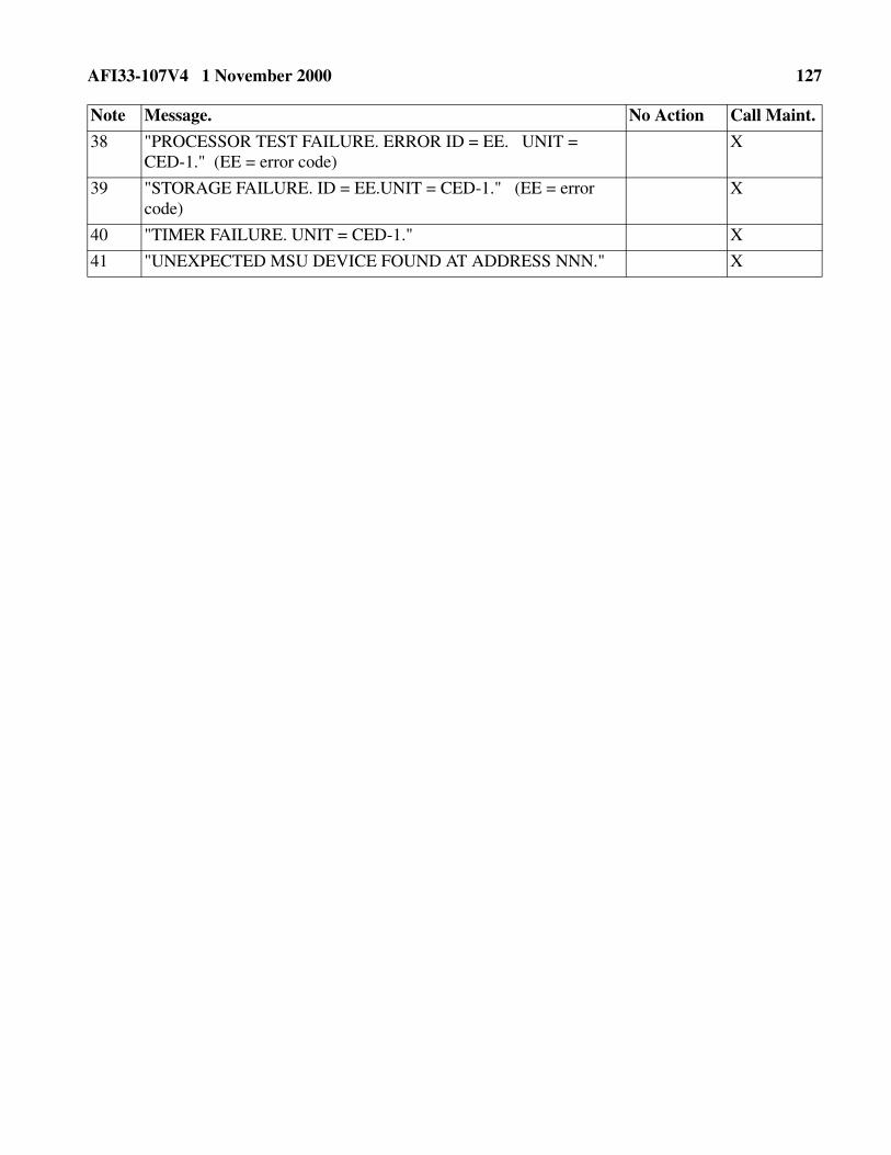
AFI33-107V4 1 November 2000 127
38 "PROCESSOR TEST FAILURE. ERROR ID = EE. UNIT = CED-1." (EE = error code)
X
39 "STORAGE FAILURE. ID = EE.UNIT = CED-1." (EE = error code)
X
40 "TIMER FAILURE. UNIT = CED-1." X
41 "UNEXPECTED MSU DEVICE FOUND AT ADDRESS NNN." X
Note Message. No Action Call Maint.

128 AFI33-107V4 1 November 2000
Attachment 22
ELECTRONIC PROGRAM UPDATE (EPU) PROCEDURES
A22.1. The EPU process is a method of updating the processor IPL diskettes in an on-line environment.After the EPU, and subsequent application, receiving sites are operating on a new software version. EPUactions are coordinated by the Offutt Subnet Communications Processor (OSCP). This coordinationserves as a guide before and during the EPU function.
A22.2. Implement the EPU under the direction and guidance of SACCS-DTS Configuration Manage-ment Office.
A22.3. Preparation.
A22.3.1. All operator inputs are entered at the SWOP (KSR-43) or the VDU/KB, if no KSR is avail-able. NOTE: When the user must "input" data, the examples are preceded by an "(I)." When the userreceives a computer "Response," the examples are preceded by an "(R)."
A22.3.2. Device 02 is the upper right MSU when you are facing the SACCS-DTS equipment rack. Itis accessed when the IPL button is in the primary position. Device 12 is the upper left MSU when youare facing the equipment. Devices 24 and 25 are the bottom right and left MSUs, respectively.
A22.4. Procedure.
A22.4.1. The SACCS NQCC, located at the OSCP, transmits a coordination message to affected sitesannouncing the EPU. The message contains the scheduled EPU time, an eight character "CRC Key,"point of contact, and the new software version release name.
A22.4.2. At the site preparing for an EPU, enter the command "PURGE" at the operator station. The"PURGE" command ensures space is available on the MENU diskette for reception of the EPU.
A22.4.3. Any pre-EPU guidance from the SACCS NQCC must be acknowledged prior to EPU com-mencement.
A22.5. EPU Commencement.
A22.5.1. At the specified time, the EPU begins and the following appears at the operator station:
NOTE: Throughout this procedure, "N" denotes the prompt number that precedes the text of the mes-sage. The user enters the actual prompt number when replying.
A22.5.2. The EPU begins after the user enters the CRC. No further user action is required until theEPU is received. When receipt of the EPU is complete, the following prints at the operator station.
(R) "N DDHHMMZ EPU (new version name) IS BEING RECEIVED,PLEASE ENTER CRC KEY."
(I) "N (CRC KEY)"

AFI33-107V4 1 November 2000 129
A22.5.3. The new version has been written to a reserved area located on the MENU diskette. Ensurethe menu diskette remains in the computer until an IPL is performed.
A22.5.4. At the OSCP's direction:
A22.5.4.1. Insert the IPL diskette in either MSU 02 OR 12.
A22.5.4.2. Ensure the PRI/ALT button is illuminated for the appropriate MSU device. Depressthe IPL button.
A22.5.4.3. Perform a normal IPL with the following change at the DTG prompt.
NOTE: The "E" option in "N DDHHMMZ MMM YY,E" copies the information written to the MENUdiskette during the EPU to the IPL diskette. The user receives normal system notifications showing con-nectivity has been established with the network. After the application has completed, the user receives thefollowing message:
The new version has been copied to the IPL diskette but is not loaded in computer memory. Thecomputer is still running on the old software version. Perform a normal (COLD) IPL to load thenew software version into computer memory. Confirm the EPU application by looking at the sec-ond line of the computer output. The second line identifies the new System ID. Confirm the newSystem ID by comparing it with the Software Version Release name given with the SACCSNQCC Coordination Message. If they are not the same, contact the SACCS NQCC.
A22.5.5. Remove the IPL diskette and insert a dump. Mark the IPL diskette with the New Version IDusing a felt tip marker and store it in a safe place.
A22.5.6. The EPU procedure is complete for one diskette. It is necessary to have the new softwareversion on all copies of the IPL diskettes. The SACCS NQCC coordinates the duplicate action.
A22.5.7. Direct questions concerning the EPU process to SACCS NQCC.
(R) "DTG EPU WRITTEN TO DISKETTE AND READY FOR APPLICATION"
INSTEAD OF: "N DDHHMMZ MMM YY,C" ("C" represents a COLD IPL)
ENTER: "N DDHHMMZ MMM YY,E" ("E" represents an EPU IPL)
(R) "DTG EPU APPLIED TO IPL DISKETTE. RE-IPL"

130 AFI33-107V4 1 November 2000
Attachment 23
REMOTE DATA-TRANSMISSION (RDT) PROCEDURES
A23.1. The RDT process transmits the information written to a DUMP (created during a restart) orJOURNAL diskette (archival journal) to the CPMF at Offutt AFB NE. The process requires the operatorat the transmitting site to change the internal diskette identifier from "DUMPFILE" or "JOURNAL" to"F0000030." The name change is the first step toward successfully completing the RDT process. Eachmount request in this procedure may differ slightly from actual mount output at a particular FA. The dif-ference is caused by the FA's configuration at IPL time, i.e., it depends on which diskette is in a device.
A23.2. Preparation.
A23.2.1. All operator inputs are entered at the SWOP (KSR-43) or the VDU/KB, if no KSR is avail-able. When the user must "input" data, the examples are preceded by an "(I)." When the user receivesa computer "Response," the examples are preceded by an "(R)."
NOTE: If the name change has been completed, skip paragraphs A23.2.1.2. thru A23.2.1.4.
A23.2.1.1. (I) "DUMP"
A23.2.1.2. (I) "N 2"
A23.2.1.3. (I) "N 2"
DISKETTE NAME CHANGE FOR DUMP TRANSMISSION
(R) "N DDMMHHZ CHANGE NAME
1. NO NAME CHANGES
2. DUMPFILE TO F0000030
3. F0000030 TO DUMPFILE
4. JOURNAL TO F0000030
5. F0000030 TO JOURNAL"
(R) "N DDHHMMZ CHOOSE POSITION FOR DUMPFILE
1-12 MENUS
2-24 EMPTY
3-25 EMPTY"
(R) "N DDHHMMZ M DUMPFILE 24 MOUNT REMOTE DATA-DUMPDISKETTE"

AFI33-107V4 1 November 2000 131
NOTE: Before answering this mount, remove the diskette that is currently in the MSU device chosen.Replace that diskette with the DUMP diskette to be renamed.
A23.2.1.4. (I) "N YES"
NOTE: The rename process is complete for the first diskette. The user will receive another filenamechange request that merely offers the opportunity for further name changes. Proper diskette maintainabil-ity and accountability allow only one diskette at a time to be renamed.
A23.2.1.5. (I) "N 1"
NOTE: The name change sequence has ended. The user is prompted to mount the newly named diskettein an MSU for transmission. Use the same MSU device used for the renaming function to decrease dis-kette swapping.
NOTE: Whatever is in MSU 12, 24, 25 will be displayed. The following is just an example.
A23.2.1.6. (I) "N 2"
DATA-DUMP DISKETTE"
NOTE: Before the user answers the prompt, contact the Offutt CPMF at the number supplied with thecoordination message. When the Offutt CPMF is ready to receive your newly named DUMP diskette, thefollowing step will initiate the transmission.
A23.2.1.7. (I) "N YES"
(R) "N DDHHMMZ CHANGE NAME
1. NO NAME CHANGES
2. DUMPFILE TO F0000030
3. F0000030 TO DUMPFILE
4. JOURNAL TO F0000030
5. F0000030 TO JOURNAL"
(R) "DDHHMMZ END OF FILENAME CHANGES"
(R) "N DDHHMMZ CHOOSE POSITION FOR F0000030
1-12 MENUS
2-24 EMPTY
3-25 EMPTY"
(R) "N DDHHMMZ M F0000030 24 MOUNT REMOTE

132 AFI33-107V4 1 November 2000
NOTE: Upon completion of the DATA-DUMP transmission, the system will output:
NOTES:1. Processing time for DATA-DUMPS will vary due to low message priority. The time
duration will be between 30-60 minutes. If a problem arises during transmission or aftercompletion, contact the Offutt CPMF. Consider anything other than a "NORMAL COM-PLETION" notice a problem.
2. The diskette (F0000030) used for transmission cannot be used as a valid DUMP until it isrenamed. If the diskette is inserted for use before being renamed, the computer will output"UNABLE TO FIND REQUESTED VOLUME - PLEASE REMOUNT."
To rename the diskette (F0000030) back to DUMPFILE, enter the following at the SWOP:
A23.2.1.8. (I) "DUMP"
A23.2.1.9. (I) "N 3"
A23.2.1.10. (I) "N 2"
A23.2.1.11. (I) " N YES"
(R) "DATA-DUMP TRANSMISSION BEGINNING"
(R)
"DDHHMMZ DUMPFILE PROCESSING COMPLETED; REASON NORMAL COMPLETION"
(R) "N DDMMHHZ CHANGE NAME
1. NO NAME CHANGES
2. DUMPFILE TO F0000030
3. F0000030 to DUMPFILE
4. JOURNAL TO F0000030
5. F0000030 TO JOURNAL"
"N DDHHMMZ CHOOSE POSITION FOR F0000030
1-12 MENUS
2-24 EMPTY
3-25 EMPTY"
(R) "N DDHHMMZ M F0000030 24 MOUNT FOR NAME CHANGE"

AFI33-107V4 1 November 2000 133
A23.2.1.12. (I) "N 1"
A23.2.1.13. (I) "N NO"
NOTE: The filename change routine has ended. Repeat this procedure to rename additional diskettesfrom F0000030 to "DUMP." Once all DATA-DUMP diskettes have been renamed, they shall be handledas directed by AFI 33-107, Vol. 2. Reinsert the previous diskette (removed in Step 3) into the MSUdevice. Reference to the inserted diskette is not possible until the processor has had an opportunity to cat-alog that device.
(R) "N DDHHMMZ CHANGE NAME
1. NO NAME CHANGES
2. DUMPFILE TO F0000030
3. F0000030 TO DUMPFILE
4. JOURNAL TO F0000030
5. F0000030 TO JOURNAL"
(R) "DDHHMMZ END OF FILE NAME CHANGES"
(R) "N DDHHMMZ CHOOSE POSITION TO MOUNT F0000030
1-02 IPL
2-12 MENUS
3-24 EMPTY
4-25 EMPTY"

134 AFI33-107V4 1 November 2000
Attachment 24
DISKETTE NAME CHANGE FOR JOURNAL TRANSMISSION
NOTE: If the name change has been completed, skip Steps A24.2 thru A24.4.
A24.1. (I) "DUMP"
A24.2. (I) "N 4"
A24.3. (I) "N 2"
DATA-DUMP DISKETTE"
NOTE: Before answering this mount, remove the diskette, that currently resides in the MSU device cho-sen. Replace that diskette with the JOURNAL diskette to be renamed.
A24.4. (I) "N YES"
NOTE: The rename process is complete for the first diskette. The user receives another filenamechange request that merely offers the opportunity for further name changes. Proper diskette maintainabil-ity and accountability allow only one diskette at a time to be renamed.
(R) "N DDMMHHZ CHANGE NAME
1. NO NAME CHANGES
2. DUMPFILE TO F0000030
3. F0000030 TO DUMPFILE
4. JOURNAL TO F0000030
5. F0000030 TO JOURNAL"
(R) "N DDHHMMZ CHOOSE POSITION FOR JOURNAL
1-12 MENUS
2-24 EMPTY
3-25 EMPTY"
(R) "N DDHHMMZ M JOURNAL 24 MOUNT REMOTE
(R) "N DDHHMMZ CHANGE NAME
1. NO NAME CHANGES
2. DUMPFILE TO F0000030
3. F0000030 TO DUMPFILE

AFI33-107V4 1 November 2000 135
A24.5. (I) "N 1"
NOTE: The name change sequence is complete. The user is prompted to mount the newly named dis-kette in a MSU for transmission. Use the same MSU device used for the renaming function to decreasediskette swapping.
A24.6. (I) "N 2"
NOTE: Before the user answers the prompt, contact the Offutt CPMF at the number supplied with theCoordination Message. When the Offutt CPMF is ready to receive your newly named JOURNAL dis-kette, the following step initiates the transmission.
A24.7. (I) "N YES"
NOTE: Upon completion of the DATA-DUMP transmission, the system outputs:
NOTES:1. Processing time for DATA-DUMPS vary due to low message priority. The time duration will be
between 30-60 minutes. If any problems occur during transmission or after completion, contactthe Offutt CPMF. Consider anything other than a "NORMAL COMPLETION" notice a problem.
4. JOURNAL TO F0000030
5. F0000030 TO JOURNAL"
(R) "DDHHMMZ END OF FILENAME CHANGES"
(R) "N DDHHMMZ CHOOSE POSITION FOR F0000030
1-12 MENUS
2-24 EMPTY
3-25 EMPTY"
(R) "N DDHHMMZ M F0000030 24 MOUNT REMOVE DATA-DUMP DISKETTE"
(R) "DATA-DUMP TRANSMISSION BEGINNING"
(R)
"DDHHMMZ JOURNAL PROCESSING COMPLETED; REASON NORMAL
COMPLETION"

136 AFI33-107V4 1 November 2000
2. The diskette (F0000030) used for transmission cannot be used as a valid archival JOURNAL untilit is renamed. If the diskette is inserted for use before being renamed, the computer will output"UNABLE TO FIND REQUESTED VOLUME PLEASE REMOUNT."
3. To rename the diskette (F0000030) back to JOURNAL, enter the following at the SWOP:
A24.8. (I) "DUMP"
A24.9. (I) "N 5"
A24.10. (I) "N 2"
A24.11. (I) "N YES"
(R)
"N DDHHMMZ CHANGE NAME
1. NO NAME CHANGES
2. DUMPFILE TO F0000030
3. F0000030 TO DUMPFILE
4. JOURNAL TO F0000030
5. F0000030 TO JOURNAL"
(R)
"N DDHHMMZ CHOOSE POSITION FOR F0000030
1-02 MENUS
2-24 EMPTY
3-25 EMPTY"
(R)
"N DDHHMMZ M F0000030 24 MOUNT FOR NAME CHANGE"
(R)
"N DDHHMMZ CHANGE NAME
1. NO NAME CHANGES
2. DUMPFILE TO F0000030
3. F0000030 TO DUMPFILE
4. JOURNAL TO F0000030
5. F0000030 TO JOURNAL"

AFI33-107V4 1 November 2000 137
A24.12. (I) "N 1"
A24.13. (I) "N NO"
NOTE: The filename change routine has ended. Repeat this procedure to rename additional diskettesfrom F0000030 to "JOURNAL." Once all DATA-DUMP diskettes have been renamed, they shall be han-dled as directed by AFI 33-107, Vol. 2. Reinsert the previous diskette (removed in Step 3) into the MSUdevice. Reference to the inserted diskette is not possible until the processor has had an opportunity to cat-alog that device.
(R)
"DDHHMMZ END OF FILE NAME CHANGES"
(R)
"N DDHHMMZ CHOOSE POSITION TO MOUNT F0000030
1-02 IPL
2-12 MENUS
3-24 EMPTY
4-25 EMPTY"

138 AFI33-107V4 1 November 2000
Attachment 25
BCP/FA POWER UP/DOWN PROCEDURES
Table A25.1. Cabinet Start-Up Procedures.
NOTE: Before any of the cabinet power switches are energized, the individual external circuit breakers must be set to ON.
CAUTION! Open MSU doors to prevent damage to diskettes.
Step Drawer Operator Control Position/Condition
1 CED POWER ON/OFF Switch ON
2 Blower POWER ON Switch
POWER ON Indicator (Green)
ON
Comes On
3 PSD RED POWER Circuit Breaker
RED POWER ON Indicator (Green)
CED-POWER ON Indicator, (Green)
28V POWER Circuit Breaker
28V POWER ON Indicator
BLACK POWER Circuit Breaker
BLACK POWER ON Indicator (Green)
ON
Comes On
Comes On
ON
Comes On
ON
Comes On
4 SFU RED POWER ON/OFF Switch
RED POWER Indicator
BLACK POWER ON/OFF Switch
BLACK POWER Indicator
On
Comes On
On
Comes On
5 MSU POWER ON/OFF Switch
POWER ON Indicator
RDY (Ready) Indicator (only when disk installed)
On
Comes On
Comes On
6 RED DC PATCH
RED POWER ON/OFF Switch
RED POWER Indicator
BLACK POWER ON/OFF Switch
BLACK POWER Indicator
ON
Comes On
ON
Comes On
7 KG-84A POWER ON/OFF Switch Comes On
8 Blower POWER ON Switch
POWER ON Indicator (Green)
ON
Comes On

AFI33-107V4 1 November 2000 139
Table A25.2. CED-1 Start-Up Procedures.
Step Drawer Operator Control Position/Condition
9 BLACK DC/VF
PATCH
N/A N/A
10 Modem POWER ON/OFF Switch
POWER ON Indicator (Green)
ON
Comes On
11 Blower POWER ON/OFF Switch
POWER ON Indicator (Green)
ON
Comes On
12 DCIU POWER ON/OFF Switch ON
13 LPU POWER ON/OFF
POWER ON Indicator
ON
Comes On
14 VDU VMA CB RESET Circuit Breaker
VDU CB RESET Circuit Breaker
POWER ON/OFF Switch
POWER ON Indicator (Green)
RESET (UP)
RESET (UP)
ON
Comes On
15 KB N/A N/A
16 KSR-43 POWER ON/OFF Switch
DATA Indicator
ON
Comes On
NOTE: Perform IPL procedure.
Step Procedure
1 Ensure that MAINTENANCE cap is in place.
CAUTION! Open MSU doors prior to turning on/resetting power supply drawer to prevent damage to diskettes.
2 Ensure the POWER ON indicator and STORAGE A and B indicators are illuminated.
3 Load the MSUs with the current system diskettes.
4 Check that PRI IPL SOURCE indicator comes on. If not, press the IPL SOURCE switch to illu-minate PRI indicator. (If this fails, use LAMP TEST switch to check indicators.)
NOTE: Alternate IPL source can be used if primary source fails.

140 AFI33-107V4 1 November 2000
5 On MSU, check that RDY indicator is ON.
6 Press IPL/LOAD button.
7 The ON-LINE indicator comes on after IPL has been accomplished.
8 KSR prints DDHHMMZ ENTER DTG, W/C.
9 ERROR indicator on the front panel of CED-1 is extinguished.
10 Enter the DTG on KSR keyboard: N 241500Z MAR 99,C (Typical Example)
NOTE: The BCP shutdown procedure is the reverse order of the start-up procedure. (Data in memory can be saved by pressing RSTRT switch on CED prior to shutdown.) After all the drawer power switches have been set to OFF, set the external cabinet circuit breakers to OFF. At this point, AC power has been removed from the BCP to the input of the circuit breaker panel.
Step Procedure

AFI33-107V4 1 November 2000 141
Attachment 26
AWCP/HFSSB POWER UP/DOWN PROCEDURES
Table A26.1. Cabinet Procedures.
NOTE: Place external AC circuit breakers for AWCP/FA to ON.
CAUTION! Open MSU doors to prevent damage to diskettes.
Step Drawer Operator Control Position/Condition
1 SFU RACK AC POWER ON/OFF Switch
RACK AC POWER ON Indicator
ON
Comes On
2 CED-1 POWER ON/OFF Switch ON
NOTE: The CED POWER ON switch can be left in the ON position.
3 Blower POWER ON/OFF Switch
POWER ON Indicator
ON
Comes On
4 PSD RED POWER Circuit Breaker
RED POWER ON Indicator (Green)
CED-POWER ON Indicator - (Green)
28V POWER Circuit Breaker
28V POWER Indicator (Green)
BLACK POWER Circuit Breaker
BLACK POWER ON Indicator (Green)
ON
Comes On
Comes On
ON
Comes On
ON
Comes On
5 KG-84A POWER ON/OFF Switch ON
6 Modem OPERATIONS POWER ON/OFF Switch
OPERATIONS POWER ON Indicator
ON
Comes On
7 MSU Open MSU Access Door
POWER ON/OFF Switch
POWER ON Indicator (Green)
RDY (Ready) Indicator
ON
Comes On
Comes On
8 SFU RED POWER ON/OFF Switch
RED POWER Indicator
BLACK POWER ON/OFF Switch
BLACK POWER Indicator
ON
Comes On
ON
Comes On

142 AFI33-107V4 1 November 2000
Table A26.2. CUTE Start-Up Procedures.
Table A26.3. CED-1 Start-Up Procedure.
Step Drawer Operator Control Position/Condition
1 VDU VMA CB RESET Circuit Breaker
VDU CB RESET Circuit Breaker
POWER ON/OFF Switch
POWER ON Indicator (Green)
RESET (UP)
RESET (UP)
ON
Comes On
2 KB N/A N/A
3 LPU POWER ON/OFF Switch
POWER ON Indicator
ON
Comes On
NOTE: Perform IPL procedure.
Step Procedure
1 Ensure that MAINTENANCE cap is not removed.
2 Ensure the POWER ON and STORAGE A and B indicators are illuminated.
3 All equipment in the AWCP/HFSSB configuration is powered up and the IPL sequence is to be initiated.
4 Load the MSU with current system diskettes: MSU 1: AWCP/FA - Program Diskette
MSU 2: AWCP/FA - Menu Diskette
NOTE: Alternate IPL source can be used if primary source fails.
5 Make sure that the PRI IPL SOURCE indicator is on. If not, depress the IPL SOURCE switch to make PRI indicator come on. (If this fails, use LAMP TEST switch to check indicators.)
6 On MSU, check that RDY lamp is ON.
7 Depress the IPL LOAD pushbutton.
8 The ON LINE indicator comes on.
9 The ERROR indicator on the front panel of CED-1 is out.
10 Line 22 of the VDU displays ENTER DTG.
11 Enter the DTG on line 19: N 241500Z AUG 98,C (Typical Sample)
12 The following notice is displayed at the LPU: DDHHMMZ START UP MESSAGE ACCEPTED.
NOTE: The AWCP/HFSSB shutdown procedure is essentially the reverse of the startup procedure. After all the drawer power switches have been set to the OFF position, set the external cabinet circuit breaker to OFF. At this point, AC power has been removed from the AWCP/HFSSB.