([WHUQDO RXWILWWLQJSeries UT™ External outfitting Series ...

AD-752 595
CONCEPTUAL DESIGN OF A MECHANIZED SHIP-YARD FOR FAST DEPLOYMENT LOGISTICS(X)PRODUCTION
Benjamin V. Andrews, et al
Stanford Research Institute
Prepared for:
S Bureau of Ships
December 1965
S~DISTRIBUTED BY:
National Technical Information ServiceU. S. DEPARTMENT OF COMMERCE5285 Port Royal Road, Springfield Va. 22151

CONCEPTUAL DESIGN OF A MECHANIZED D D CSHIPYARD FOR FDL(X) PRODUCTION '-7 --"
P r ,,lo r ,,d to ,r:. |El i 1 02
FDL PROJECT OFFICE L L I]"'-UBUREAU OF SHIPS
BDEPARTMENT OF THE NAVYWASHINGTON, D.C.
1Ap~2 z "d for Pu&b~i relecim17ý9• u l utlo n U ulw wl d
NATIONAL TL::CHINICALINFORMATION SERVICE
""4 •, CALIFORNIA
4v!

JU'NC11 1I
S-- list.
iA

Iec•iucr 1965'
CONCEPTUAL DESIGN OF A, MECHANIZEDSHIPYARD FOR FDL(X) PRODUCTION.
Prepared for:
OFDL PROJECT OFFICEBUREAU OF SHIPSDEPARTMENT OF THE, NAVYWASHINGTON, D.C.
By: BENJAMIN, V. ANDREWS AND DAN G. HANEY
S'Ri Fro/ect ill -7,l
_woo
m rumvte A.*ks9

PREFACE
This report describes the results of a two-month study of the concep-tual design of a mechanized shipyard for FDL(X) ship production. Thestudy was conducted by three organizations. Stanford Research Instituteheld the prime contract and was assisted by Bechtel Corporation and thenaval architecture firm of Morris Guralnick Associates.
The Institute's responsibilities included analyses of modern shipproduction methods and shipyard layouts, the synthesis of a yard designthat might prove effective in FDL ship production, and studies concerningthe effects of mechanized production processes on the ship constructionprogress curve. Mr. Dan G. Haney, Manager of the Systems Economy Researchprogram, was the project leader. Mr. Benjamin V. Andrews, Naval Architect,was the principal analyst. Mr. Robert Meister, Operations Analyst, con-tributed to the synthesis of the conceptual design.
Bechtel Corporation had responsibility for the construction engineer-ing of the shipyard necessary to estimate the yard cost and constructiontime. Bechtel also assisted in analyses of production methods materialflow, and layout of the yard. Mr. Kenneth Broome actod as Bechtel's proj-ect leader and was assisted by Mr. Byron Leonard.
Morris Guralnick Associates (MGA) was responsible for the analysisof the FDL(X) pre!lminary design and assisted in assembly sequence studies.Capt. MacKinnon Lansdowne, U.S.N. Ret., and Mr. William Warren were theprincipal contributors from MGA.
The vali )le information obtained from Gbtaverken Ab, AB Burmeisterand Wain's, Kieler Howaldtswerke, from the other shipyards visited duringthis study, and from many European machinery suppliers, is gratefullyacknowledged.
This report includes the material presented to the FDL Project Officein the December 16, 1965 oral briefing and provides additional backupmaterial developed during the research.
Preceding page blank
iii

CONTENTS
PREFACE . . . . . . . . . . . . . . . . . . . .. . .. . . .
I INTRODUCTION . . . .. .. .. .. .. .. .. ..
I I SUMMARY s . . . . . . . . .. . 0.. . 9. .. . .. . .
III SHIPYARD MODERNIZATION IN EUROPE. ... ... 11
Production Methods . . . . * . 0 ... . . ........... 11Steel Processing . .. .. .. .. .. .. .. . .... 11
Assembly . . . . . . . . . . . . . . . . . ....... .12
Erection . . . . . . . . . . . ..... . . . . ................. .. 13Progress Curves ... ........... ... 18Production Control .......................... 21Ship Design . . . . . . . . . . . . . . . . . . . . . . . 22
IV THE FDL(X) SHIP . ........... ... .................... 25
FDL(X) Description .......................... .... 25
V SHIPYARD LAYOUT . . . .................. . . ............ 35
Manufacture or Purchase ................ 35Steel Processing Area ............. ................ 37
Storage Yard ................... .................... .. 37Steel Processing Building ...... .............. .... 39Process Storage Areas .. ....... .............. .. 39
Main Assembly Building .............. .................... 40Panel Production .u. n.................. ..... 40Assembly . ....................... ... ... . . . ...... . ... ... 42Outfitting ................ ..... ................ .. 43Erection ......................... ............. ... 45
Completion .................. ................. ..... 49Shipyard Layout ................. .............. .... 50
VI CONCEPTUAL SHIPYARD DESIGN AND CONSTRUCTION ....... ... 53
Sites Conditions and Development ..... ........... .... 55Docks ................... ....................... .... 58Buildings ...... ............. ... ...................... 59Materials Handling Equipment ....... ............. .... 60Production Machinery .......... ................. .... 60Design and Construction Schedule ..... ........... .... 61
Preceding page blank v

CONTENTS
VII CONCLUSIONS . . . . . . . . . . . . .. 65
Suitability of Production Lines . . . . . . . . . . . . . . 65Application of the Arendal Erection Principle . . . . . . . 65Shipyard Flexibility for Construction of Other Ship Types . 67
APPENDIX A FDL(X) SHIP DESIGN ASSEMBLY WEIGHTS . . . . . . . .. 71
APPENDIX B ASSEMTLY DATA .A............. .. ... 73
APPENDIX C FDL(X) MANUFACTURE OR PURCHASE LIST . . . . . . . .. 77
APPENDIX D FDL(X) ERECTION SCHEDULE .............. 81
APPENDIX E MAJOR SHIPYARD MACHINERY ....... ........ ..... 83
APPENDIX F MACHINERY MANUFACTURERS, THEIR U.S. REPRESENTATIVE,AND THEIR PRODUCTS . . . . . ....... ................ 87
vi

ILLUSTRATIONS
1 The Arendal Shipyard ........ . ....... 3
2 Comparison of Four Erection Layouts for Shipbuilding Yards 14
3 Burmeister and Wain's New Shipbuilding Facilities . . . .. 16
4 Arendal Erection Principle ............... 17
3 Shipbuilding Progress Curves ............... 19
6 FDL(X) Profile View ..... . .. .. .. .. . . . .. . 27
7 FDL(X) Assembly Arrangement--Sections 9 and 10 . . . . . 29
8 Typical FDL(X) Assemblies ........... .... 30
9 Assemblies for FDL(X) Section 10 . . . .......... 31
10 Deck Arrangements for FDL(X) Section 10 .... ...... .... 32
11 FDL(X) Shipyard Concept ...................... 36
12 Steel Processing Area .. ........ ....... 38
13 Main Assembly Building . . . . . . . . . . ....... 41
14 Assembly, Outfitting, and Dock Area . . . . . . . . . . . 44
is FDL(X) Station Activity ........................ 46
16 FDL(X) Ship Erection Schedule (Partial) ...... . ... 48
17 Shipyard Layout ...... . . . . .......... . . 51
18 Shipyard Site Description ........................ 56
19 Shipyard Design and Construction Schedule . . . . . . . .. 62
TABLES
1 Mechanized Shipyard Cost Estimate .... ............. ... 54
vii

I INTRODUCTION
Background
The capability to deploy rapidly large numbers of military equipmentand vehicles to overseas areas is becoming increasingly necessary to theDepartment of Defense. Past studies and experience have indicated thedesirability of possessing extensive transportation resources for movementof troops and supplies in crises and limited war situations. Currently,air transportation can provide airlift of troops, small arms, and limitedquantities of mechanized equipment. However, transportation demands formechanized equipment for major military units far exceed the planned air-lift capabilities. The Fast Deployment Logistic vessel (FDL) conceptfills the need for advanced, prepositioned, mobile equipment supply sources.
The FDL ship performance characteristics have been defined to includethe ability to load and dischargc vehicles and cargo by roll on/off, lifton/off, swim on/off, and telicopter methods. A relutively fast, sustainedsea speed is desired to provide rapid deployment of entire mobile armyunits, and an unusually high standard of dependability is also desiredfor long voyages where repoir facilities are not available.
The U.S. Navy is prepared to support a program of studies to exploreand evaluate charafcteristics of mechanized production for the FDL 3rogreA.
To initiate this program, contractors will be presented with examples andillustrative material outlining at least one approach to mechanized con-struction and indicating the nature of the advantages that may be realized.
The number of FDL ships to be built may be so large that conventional,multipurpose shipbuilding yards may be less efficient than a highly mech-anized and specialized yard designed for FDL construction. As additionalquantities of one ship design are built, an increase in the number ofunique facilities and mechanized production arrangements could reduceshipbuilding costs. The production line configuration of World War IIshipyards, designed to produce more than 100 ships of a single type, isan example of such specialization. At present, few shipyards in the worldhave orders for large enough numbers of similar ships to benefit frommechanized production techniques.
Many shipyards in the United States, West Germany, England, and Japanhave achieved improved efficiency in materials handling and flow, and alsoin fabrication and assembly processes. New advances in production plan-ning and the use of computers for numerical control of machines and otherpurposes are being developed. An outstanding example of some of thesetechniques and developments is provided by the bulk carrier and tankeryard at Arendal, Sweden, This study focused on the feasibility of incor-porating techniques used in the Arendal shipyard in the yard configurationfor FDL(X) construction, the Bureau of Ships preliminary design of the FDL.
1

The Arendal Shipyard
The Arendal Shipyard, one of three shipyards operated by the G6taver-ken CompAny, is located near Gothenberg, Sweden. It has received consider-able attention in the press and from persons in the industry because ofits use of new concepts in ship construction. Arendal's ship erectionprinciple--extruding ships out of an assembly building into a buildingdock--can be distinguished from its total yard concept of productionprocessing. Arendal can be of considerable assistance in evaluating thepotential of new shipyards, for it is a unique, completely new facilitywhose construction was not restricted by old buildings or production tech-niques. Arendal is shown in the perspective drawing of Figure 1. As aresult of its unrestrained approach, Arendal has made progress not onlyin improving the method of erection of ships, but also in productionprocesses throughout the entire shipyard. For example, while the steelprocessing facilities are not an essential part of its erection principle,impressive advances in this area have been made. However, many of thesteel processing improvements at Arendal are rather common elsewhere inEurope and are being adopted in this country. The study team also as-sessed modern techniques used in ship construction in other shipyards.
The Arendal erection principle is suitable for building tankers andbulk carriers, which require relatively little outfitting and concentratealmost all machinery in the aft hull sections that are built first. How-ever, FDL(X) ships are much more complicated than ships built at Arendaland are outfitted throughout their length, within the bottom and on theupper decks. Further, the weather at U.S. shipyard locations is notusually as demanding of enclosed space as is the Swedish climate. There-fore, the concepts and design of the Arendal yard cannot be adopted ex-actl.,, but must he tailored to reflect the U.S. weather conditions andFDL ship design. The Arendal concept was adopted as the model for thisstudy, not necessarily because it was considered the best or the onlyway to build the FDL(X) ship, but because of the considerable interestand attention in the possible application of this principle to FDL con-struction.
Objectives
The objectives of thig research report are: (1) to outline a con-cept applying modern manufac'uring techniques to the development of amechanized yard for the construtction of FDL .hips, and (2) to provide apreliminary assessment of the yard capixtal cost and its production rate.
Method of Approach
The major steps included an analysis of the FDL(X) ship design andthe principal interfaces between ship design and shipyard design; thedescription of the functional operations required in ship fabrication,assembly, erection, and outfitting; a synthesis of an overall shipyard
2

94I
iI~ii)
to - -
-LJ
LL

patterned after the Arendal principle; and analyses of costs and produc-tivity of a modernized shipyard. Development of the mechanized shipyardconcept was based on field work at modernized European shipyards. Thescope of the study did not include an estimate of the construction costof the FDL ship.
Certain criteria have been used as guidelines in formulating a con-cept of a mechanized shipyard for FDL(X) ships. Because of the limitedtime available, the study focused on the development of only one of themany alternative approaches to new shipyard design. A number of methodsfor accomplishing some of the different production tasks required in thetotal shipbuilding p:ocudure were considered, but selection of methodswas based largely on intuitive judgment, rather than on quantitativeanalysis. Considerably more study is necessary before it could be statedthat a particular concept, or a particular sequence of detailed productionoperations, is the optimal method of building the FDL(X) ship.
A guideline for shipyard design is that construction of 5 to 30 FDLships would be required per year. The concept presented in this reportresulted in an estimated basic production rate of 6 ships per year. Thisrate would be increased to 12 ships by resorting to two-shift operation,and to 24 by duplicating most of the facilities of the yord.
The study team assumed that a new yard constructed principally forFDL(X) ship production would be used for some time after completion ofthe FDL program. If a new yard proves more attractive then existing fa-cilities for the construction of the FDL ship, it shoitld also be competi-tive in the U.S. market for production of other types vf ships. Thus,there probably would be continuing production from the .iew yard, Theassumption was adopted that the yard would have a relatively long life,and also that it would be capable of building a number of different shiptypes.
A typical site was chosen for a new shipyard rather than a specificlocation. The site is assumed to be located on the northeast AtlanticCoast--Chesapeake Bay and north--at the mouth of a river that is protectedfrom severe seas and within approximately 10 miles of a city of 100,000 pop-ulation. In addition, utilities of all types are assumed to be available.Some snow and some rain would be expected at the shipyard location.
The yard design is based on the assumption that the yard would manu-facture only those items which form the ship's structure, or which comprisethe piping and duct systems of the ship, and that it would install pur-chased equipment. Accordingly, steel processing activities and hull fab-ricatioa activities are the primary manufacturing operations. The ship-yard ii asstmed to purchase all shipboard machinery, equipment, outfittingitems--Including furniture--and additional material such as propellers,shafts, and shipboard materials handling equipment. This assumption per-mits the study to focus on the major operations concerned with the actualprocess of shipbuilding, Also, the cost of the yard is reduced by elimi-nating the need for specialized manufacturing facilities that may alreadybe available within the maritime industry.
4

Guidelines for Serial Production
A number of related guidelines have been adopted for the synthesisof a mechanized shipyard for FDL(X) serial production.
First, production line processei can and should be installed in ship-building and used in preparation of outfit, machinery, and hull engineer-ing.,* The attributes of production line processes include: Materialtransfer is handled by more or less automatic means, and labor becomesmore proficient in work by specializing in a single job that can be re-peated in a single location,
Second, special jigs and fixtures can be designed in serial produc-tion to expedite much of the fabrication process, both in and off theproduction lines, An example is the jigs used to preposition stiffenersprior to setting them on the plates.
Third, many parts of the FDL(X) ship design may need changes toimprove efficiency on production lines and in final ship assembly anderection. Close liaison between those responsible for ship design andthose responsible for accomplishing its construction can be maintainedby a production engineering staff that recognizes the problems of both.t
Fourth, one way to reduce the large amount of labor required infitting-out operations is to permit a major share of outfit to be placedin assemblies before they are placed on the ship. Much fitting-out laboris tied up in transporting the workman, his tools, and his materials toa specific location within the ship. These movements can be reduced bylocating the assembly directly adjacent to the outfitting area.
Fifth, contrary to pre.ent practice, labor should be assigned toperform all of the duties necessary at a specific location, rather thanassigned by particular craft association and skill to jobs at varyinglocations, If more repetitive work can be performed in particular areas,such as on production lines or within particular shop production areas,labor assignment to specific stations is more possible.
Sixth, many proposed shipyard production lines could be mechanizedto an extent not currently known in the United States, However, existingshipbuilding methods could not be so mechanized. Computer control of
* The single descriptive term of "outfit" used throughout this reportrefers to the installation of these components in the steel hull..
t A number of European shipbuilders indicated a strong preference tohave their own staff design the ships produced for their customers.The shipbuilders claim that production savings result from in-housedesign and are reflected in lower prices for their ships. At Bur-meister and Wain's yard, almost 10 percent of the total direct laborforce is engaged in production engineering.
5

machines and of jig setup is an accomplished fact, and the FDL programmay be able to extend these advanced techniques to translate automaticallyship design data into production engineering data for many processes andproduction lines.
Finally, reduced ship construction cost resulting from mechanizedshipbuilding can be achieved only if precise production control activitiesare available at a new shipyard. To prevent disruption of the flow ofmaterials, the men, machines, and materials must be available at the pre-cise time they are needed. An expansion of the production control functionover that now available is necessary to ensure smooth manufacturing ofparts and assembly of ships.
6

II SUMMARY
Shipyard Modernization in Europe
Significant improvements in ship construction techniques have beenintroduced in European shipyards in recent years. These improvementshave resulted from the economic impact of foreign competition--especiallyJapan--and from technological development that has forced shipbuildersto enlarge facilities for construction of larger ships.
in steel processing operations, mechanized materials handling, auto-matic flame cutting of steel plates, automatic fabrication of large gird-ers, and cold frP'3 bending are some of the improved production methodsthat have been implemented.
In the fabrication of assemblies, shipbuilders have improved effi-ciency by installing mechanized production lines for flat panels anddecks, introducing automatic welding machines, and by using computer-generated production and production control guidelines. A tendency to-ward the fabrication of very large assemblies prior to ship erection isprevalent, requiring lifting capacities of large cranes on the order of300 to 600 tons. Modernization usually includes adoption of the principlethat all assembly operations should be accomplished indoors.
Three shipyards have introduced revolutionary, but distinctly differ-ent methods of ship erection., These yards are Arendal, Sweden; Burmeisterand Wain's, Denmark; and Kieler Howaldtswerke, Germany. All three usebuilding docks rather than launching ways and intensively use the dockto maximize ship production rates, Arendal erects ships indoois, whilethe others accomplish these operations outdoors.,
Substantial improvements in outfitting operations have not takenplace to the same degree as those in other operations. However, accom-plishing outfitting operations is desired as early as possible in theshipbuilding schedule.,
Shipyards using more conventional shipbuilding technique., as wellas those that have introduced mechanized techniques, have experiencedlearning or progress that results in a continual decrease in labor hoursin producing large numbers of ships. However, in initial operations therecently modernized yards have experienced higher costs for the first fewships than if the ships were built by conventional methods. More rapidprogress toward low costs offsets the higher initial cost of new yards,.
7

The FLD(X) Ship Design Analysis
The Bureau of Ships preliminary design of the FDL(X) was used toprovide a basis for design of production operations, selection of produc-tion equipment, and for sizing and balancing production flow. The shipdesign was divided into 16 sections, and then into some 90 principalassemblies, whose weights frequently exceed 300 tons. Major assemblytypes found throughout a major portion of the ship's length are the bottomassemblies, side assemblies, and vehicle decks. Because of the largenumbers of these assemblies, special facilities might be justified fortheir production in the yard.
Assemblies were further divided into subassemblies and fabricationsin order to estimate the size and number of production facilities thatwould be needed in early stages of a ship's construction schedule.
The Mechanized Shipyard Concept
Mechanized facilities are provided in the steel plate and shape andpipe storage areas for receiving and preparing materials for processing.Materials move by conveyors through the preparation machinery to areasfor cutting and shaping, Processing equipment to produce repetitivelyeach kind of steel pipe, plate, or shape, is located along the materialflow lines. Conveyors and cranes are provided to expedite movement andmaximize utilization of expensive equipment, Storage for materials inprocess have been provided to smooth production flow and facilitate fur-ther production. Flat plates and shapes move by conveyor to the mainassembly building.
The semiautomatic fabrication of flat, stiffened plates into subas-semblies is done on five conveyor production lines for the largest deckpanels, for vehicle decks, and for small bulkhead and deck panels, Thepanels are moved to other areas for bottom, upper and lower side, anddeck house assembly fabrication.
Curved plates and shapes are moved by vehicle. Curved shell panelsare fabricated on contoured jigs., Panels are joined into subassembliesin positioners to expedite welding, and the lighter subassemblies aremoved by cranes into assembly areas serviced by heavier capacity cranes.,After structural fabrication of assemblies is complete, foundations, pip-ing, machinery, and outfit are installed while Each assembly is easilyaccessible to outfitting shops.
The outfitting shops are centrally located so that purchased mate-rials canflow into the warehouse and through the outfitting building, to
the outfitting assemblies, to the building dock, and to the outfittingwharf. The shops are arranged as production lines for items such asventilation ducts, heads, electrical cable harnesses, and small pipesystems,
8

Each assembly, with outfit installed, is lifted into the FDL(X) atthe appropriate time and at one of the five stations in the building dock.After two or three 8-hour work shifts, the completed structure of the shipis pushed stern-first 40 feet out of the assembly building. About 40 workshifts are needed to erect all assemblies and complete the underwater hullbefore launching the ship. During this time, installed outfit can be con-nected and completed. Almost all producticn is indoors,
After launching, the FDL(X) is towed to the two-level outfittingdock, which provides direct access to the FDL(X) ship at the main decklevel and at the fourth deck side ports. After final tests are performed,and the ship is complete, and sea trials are passed, the FDL(X) is deliv-ered before the subsequent ship is launched. With one work shift daily,six ships could be produced per year, or twelve ships with two-shiftoperation,
Yard Construction Time and Cost
A typical site for the conceptual shipyard was selected on the Atlan-tic Coast north of Hampton Roads. About 140 acres of flat land are desir-able for a one-building dock yard, and twice that area is necessary todouble production. Since a large fraction of the total yard area is cov-ered by buildings, or parking space for employees' autos, a more suitableterm than shipyard may be ship building plantc
The cost of the one-dock yard is estimated to be $80 million, and$144 million for a two-dock yard. Land costs, hand tools, and toolingfor the FDL(X) would be additional expenses. The one-dock yard could beconstructed in 30 months if extensive ship design, industrial and con-struction engineering, and material procurement are completed in advance.Parts of the yard could be available prior to the end of construction.
9

III SHIPYARD MODERNIZATION IN EUROPE
The major shipbuilding yards in Europe are altering their layoutsand facilities to achieve production line goals. The extent of modern-ization varies widely at variou; yards. Most yards have rationalized theflow of steel into and through initial storage, preparation, and cuttingareas. Several yards have production lines for small fabrications, butvery few have extended production line techniques into the assembly andoutfitting of entire ships. This chapter describes notable aspects ofproduction changes completed or contemplated.
Production Methods
The principles of production lines and their application to ship-building as described in the Introduction are relatively simple. On theproduction line, the parts being fabricated move past a series of workstations, where each employee in turn repeats one specific process.Each employee performs all the steps required at his station. Tools andsupplies are delivered to the employee at the rate needed to maintainproduction without delays. After passaig through all the work stations,the product is complete.
In some cases, such as erecting tall buildings and large dams, thematerial being fabricated cannot move past a laborer at his normal work-place. In this case, the laborer moves about on the job, taking his toolsand supplies with him to each task. Shipbuilding is usually consideredwithin this category of construction. In this study, we have describeda ship production line in which the material being produced moves past thework stations. Not only the steel pieces, but entire decks, engine rooms,and even the ship itself are manufactured on production lines. The pro-duction lines described here are feasible combinations of production lineprinciples and current technology. Further improvements to achieve thehigh labor efficiency inherent in mechanized or automatic productionlines could be implemented with detailed study.
Steel Processing
Movements from storage and preparation of steel plates and shapesprior to fabrication has become a highly mechanized production line atalmost all large European shipyards. The unloading of delivery vehicles,rolling the steel to make it straight, cleaning of mill scale, primepainting, cutting, and delivery to the fabrication areas are generallyperformed mechanically by 10 to 30 men. A production line is usuallyestablished up to the cutting steps, with the same sequence of operations
Preceding page blank 11

described above. Conveyor lines could be extended to load and unloadcutting machines. Each of the preparation operations is usually done bya single machine at each station along the conveyor carrying eitherplates, shapes, or both.
Many different manufacturers produce roller leveling, shot blast,prime painting, cutting, and conveying machinery. (See Appendix F fora partial listing of manufacturers.) Very few of these machines are in-stalled in U.S. shipyards.
In some European shipyards, the line or flow of material is not ac-complished by conveyors. In these yards, the management complained ofthe bottleneck in processing rate due to inadequate materials handlingequipment. In the fully mechanized steel processing layouts with con-veyor lines, a single equipment of each type was considered more thanadequate for enormous annual throughputs of steel. The interrelationshipof production equipment throughput and matching material handling equip-ment was clearly demonstrated by this contrast.
Assembly
The fabrication of subassemblies and assemblies and erection of theship hull were not accomplished as uniformly as the steel processing atthe various European shipyards. For example, the basic operation of weld-ing plates together and then welding stiffeners to the plates was accom-plished in several sequences. The traditional method of placing theplates on the building way and welding plates together in place was notobserved in any European yard visited, except in special circumstances,such as bilge strakes riveted on a seam.
In most yards, a hull shell area or part of a bulkhead is fabricatedin place on a welding platen. Plates are joined, and stiffeners arefitted and welded individually by manual procedures. Traditionally,workers are moved from fabrication to fabrication as needed. No otherwork is done on the fabrication before lifting it into place in an assemblyor on the ship in the building way. Lift weights up to 30 or 40 tons werecommon using this production method.
Two shipyards have established production lines for manufacturingbulkheads, decks, or flat shell plating. Steel plates and shapes aresupplied at the start of a conveyor. The production sequence is the samein each line. At the first station, plates are joined by automatic butt-welding machines. At the next station, the location of stiffeners ismarked on the plates, and edges are trimmed. The stiffeners are some-times tack-welded after being placed. At the third station, automaticmachines weld each stiffener, sometimes without tacking. These panelproduction lines are manned by relatively few men, each specializing inonly one operation. These lines are indoors and reportedly achieve greatreductions in cost of producing flat, stiffened-plate panels.
12

Large assemblies are prepared in a few shipyards by joining shell,deck, or inner bottom fabrications on the building platen, usually out-doors. The weights of these assemblies ilvariably are limited by cranecapacity available in each building way. Installation in assemblies offoundations, machinery, and outfit is also limited by the added weight-lifting capacity needed. Lifts of up to 120 tons are needed for erectionof supertankers and large bulk carrier assemblies by conventional methods.The same building techniques were used in many U.S. World War II ship-building programs.*
Erection
The conventional erection layout is shown on Figure 2. Assembliesfabricated adjacent to the launching way can be lifted into place on theship by one or more portal cranes. Almost all U.S. and foreign yardserect ships by the conventional techniques.
The most advanced ship-erecting techniques were observed at the fewyards that were not handicapped by limited weight-lif.ing capacity. Inthe well-equipped yards, lifts of 200 to 600 tons could be assembled in-side buildings and transported to the launching way or building dock. Inthe process of transportation of the very large assemblies, a delay wassometimes planned near the shops, so that outfit could be installed inthe assembly. Piping and foundations were often completed prior to erec-tion; some equipment was installed; and occasionally even painting andsheathing was begun while the assembly was easily accessible.
The particular method of lifting and erecting these very heavyassemblies is especially important to this study, because different meth-ods may result in different yard layouts, costs, and benefits.
The most advanced European yards for handling large assemblies wereArendal of Gotaverken near Gothenburg, Sweden; Burmeister and Wain's atCopenhagen, Denmark; and Kieler Howaldtswerke, Gaarden, Kiel Germany.All three yards erect ships in a building dock, not on ways.t Thesketches of Figure 2 depict the layouts of the assembly halls, buildingdocks, and largest cranes at these yards. Figure 2 also depicts a commonlayout of a conventional shipyard launching way or building dock.
* For a complete description of shipbuilding techniques in the UnitedStates prior to and through World War II, see The Shipbuilding Busi-ness in the U.S.A., Volumes I and II, by the Society of Naval Archi-tects and Maine Engineers, 74 Trinity Place, New York 6, New York,1948.
t The managements of most European shipyards are convinced that theextra cost of a building dock over a launching way is rapidly repaidby savings due to increased production efficiency.
13

o 4
-U
4 4
a A
v~
4A~
e e
u-i
0.
U'-
0 o0 0
o so
zz.0U
0~
4. 0In I***d o
_I L\

The Burmeister and Wain's (B&W) ship erection layout is perhaps thesimplest of the three advanced yards. A pair of 300-ton gantry cranes
on tracks straddle the single building dock, and the tracks extend hun-dreds of feet inshore from the building dock into a main assembly building.A subassembly building, adjacent to the main assembly building, is servedby a pair of 120-ton gantry cranes. Movements of subassemblies from thearea served by the 120-ton cranes to that served by the 300-ton cranes isaccomplished on a tracked transfer vehicle in front of the assembly build-ings. The cranes and buildings are illustrated in the photograph, Figure 3.
The Kieler Howaldtswerke yard is being completed with a differentarrangement of cranes to serve both the building dock and assembly build-ing. A single gigantic gantry crane straddles the erection dock and theassembly hall, and an open space between the two. The assembly buildinghas a segnented roof on rollers that can be moved away from the top ofeach assembly that is to be lifted out of its place of fabrication anderected on the hull in the dock. The crane span must be long and highenough for any lifted section to clear the assembly building walls. Thisarrangement was chosen because of inadequate space available at the head
of the dock.
Both Burmeister and Wain's and Kieler Howaldtswerke are able to erectassemblies at any place on the hull in the dock. However, only one or twolarge cranes of 300-ton capacity can service the building dock, and canalso assist in moving heavy assemblies during fabrication. Both yardstransport subassemblies of much lighter weight to the main assembly build-ing, and both attempt to install as much machinery and outfit as possiblein each assembly prior to erection.
The Arendal shipyard uses a substancially different technique thanthe conventional methods described above. The technique has been nick-
named the toothpaste technique because the ship is extruded out of anassembly hall as it is being erected, instead of being erected in place.
In the design of its yard, the Arendal staff was faced with the needto provide capability for year-round production. To ensure maximum effi-ciency during all types of weather, most ship assembly and erection opera-tions are accomplished indoors. The Arendal principle permits indoor erec-tion of ships without requiring a building that covers a ship's entirelength. The important features of the Arendal erection principle areillustrated in Figure 4. The main assembly building is served by heavy-lift cranes. A part of the building dock is inside the main assemblybuilding, and a pushing mechanism is located at the floor of the buildingdock.
Arendal divides each tanker or bulk carrier into a number of sectionsthat essentially are formed by vertical slices perpendicular to the lengthof the ship. Within each section, enough assemblies are fabricated tolimit lift weights to less than crane capacity. A number of assemblies
that are fabricated in the main assembly building are erected in the dockto complete each section. When a complete section of a ship is erected,
15

Lt)
0Zcc
LLI-
zU.'
uu-
caV

Lim C t
-JJ i.1.
ac
o =c
1 13*.u
-a
0 =1
. w3MOB

the hydraulic mechanism pushes the ship out of the main assembly build-ing for one section of its total length. Work can then be started onerecting new assemblies for the next sections. The sections at Arendalare generally about 13 meters, or 40 feet in length, and space is avail-able in the dock for work on two sections of a ship at a time.
Another important feature of the Arendal yard is the ability of thecranes to serve the erection area in the building dock from a number ofdifferent directions. The heavy-lift cranes shown in Figure 4 can liftassemblies into the dock from either side of the dock; in addition, assem-blies can be lifted from a location directly behind the dock into theirrequired position in the ship. Thus, the Arendal erection principle con-centrates fabrication and erection of a ship in a relatively small areaserved by heavy-lift cranes.
The Arendal concept is not universally accepted as the most econom-ical method of ship construction; other European yards are convinced thattheir assembly tichniqttes ure also quite efficient. The Burmeister andWain's yard presents an interesting contrast to Arendal. Here, the fab-ricating of assemblies is accomplished indoors, but the entire assemblyof the ship is done outdoors in a building dock some distance from theassembly buildings. Although in similar climates, the two yards haveadopted substantially different erection principles, partially because ofdiffering site conditions. Arendal accomplishes all ship erection workIndoors in a very intensively utilized work area; B&W concentrates itseffort by enclosing work associated with fabrication of assemblies, butperforms final ship erection activities in an open building dock.
The effect of weather on ship construction labor hours is an ex-tremely important aspect of the location and economics of a new shipyard.The arguments for and against enclosed building docks have not been stud-ied to an extent that shipbuilders agree on the degree to which enclosedassembly docks are justified in relation to weather conditions. Obvi-ously, the choices made by Arendal are predicated upen the convictionthat all work must be done indoors. This climatic fac.o' is nvt as imper-ative for all potential FDL shipbuilders.
Progress Curves
The beneficial effect of learning or progress on the unit construc-tion cost of ships* is an important justification for the expenditure fornew shipbuilding facilities. Figure 5 indicates estimates of the ship-building unit progress curves for direct labor man-hours--a cost indi-cator--under two diff'>ent conditions. The data from which these curves
* The theory and application of progress curves is discussed in HaroldAsher, Cost-Quantity Relationships in the Air Frame Industry, RandCorporation report R-291, July 1956.
18
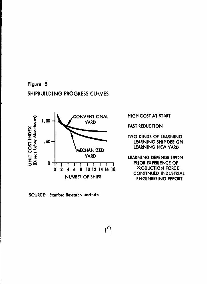
Figure 5
SHIPBUILDING PROGRESS CURVES
0 CONVENTIONAL HIGH COST AT START1.00- YR
1x FAST REDUCTION
z TWO KINDS OF LEARNINGS,50- LEARNING SHIP DESIGN
03 LEARNING NEW YARDMECHANIZED
YARD LEARNING DEPENDS UPON0- PRIOR EXPERIENCE OF
0 2 4 6 8 10 12 14 16 18 PRODUCTION FORCECONTINUED INDUSTRIAL
NUMBER OF SHIPS ENGINEERING EFFORT
SOURCE: Stanford Research Institute

were derived were obtained from ship producers, both in Europe and theUnited States. The curves reflect an estimate of the progress that mightdevelop under comparable shipyard construction of a series of ships. Thecurve labeled "conventional yard" indicates the 94 percent slope unit pro-gress that might be expected on a new ship by a shipyard staff that isaccustomed to working with conventional American shipyard equipment, fa-cilities, and layout. The second curve labeled "mechanized yard" indi-cates the type of reduction in unit construction direct man-hours thatmight be experienced for a new modernized yard of the types described,with about 84 percent slope.
Perhaps the two most important facts observed from the data are thata considerably higher cost should be expected for the first few shipsproduced in a modernized and new yard, and that relatively fast reductionin cost can be expected after the new yard is put in operation.
The basic reason for these facts is that two kinds of learning takeplace with a new modernized yard. First, the production staff, the fore-men, and production control and management personnel are learning a newship design and benefitting from that learning process. Second, with a".odernized yard, they are learning to operate the new yard itself. Costsmay reasonably be expected to be 10 to 20 percent higher for the firstship than if it were built in a conventional and efficiently operatingyard. However, as the yard force becomes accustomed not only to the shipdesign, but also to the facilities of the new yard, progress takes placemore rapidly. After a relatively small number of ships are produced, thenumber of direct labor man-hours should be considerably lower for themodernized yard than fo;. the conventional yard.*
The amount of learning should depend to a considerable extent on(1) the prior experience of the production force, and (2) the degree towhich industrial engineering or producticn engineering efforts are con-tinued.
If a new shipyard is located where labor has little prior experiencein shipbuilding, very rapid progress of the shipyard force might be ex-pected, but may start off at a relatively high cost level. On the otherhand, if a work force having considerable prior experience is employed,the slope of the unit cost curve should be considerably less, and reason-ably should start off at a lower cost level, i.e., less progress and lowerinitial ship cost.
The average direct labor cost per ship may be equal in conventional andmodernized shipyards at about the fourth or fifth ship. However, largesetup costs and capital investment costs are incurred with a modernizedshipyard that must also be repaid by direct labor savings to reach trueequal ship cost, or equal total costs of production.
20

Continued industrial engineering effort should result in continualreduction in the man-hours required to manufacture ships. The data used toderive the curves shown in Figure 5 reflect a dynamic situation in whichmanagement and engineering staff are making continual changes to improvethe production efficiency, not upon a static situation in which a yardforce goes to work under fixed conditions. The areas of production con-trol refinements and ship design improvements to reduce production costsare two obvious areas ihere continuous changes can be accomplished.
The data underlying the progress curves are typically found at con-ventional American or at modernized European shipyards. Newer shipyardscan be conceived that are more automatic or that are specialized to pro-duce many ships of one type. At the present state of shipyard mechani-zation, further replacement of manpower with machines can be expected toresult in greater tooling and set-up costs, and higher direct labor hourexpenditures on the initial ship. However, the progress curve slope maybe even steeper as a result of faster learning on subsequent ships iffurther mechanization is provided.
The precise progress curve slope and higher initial unit cost com-bination cannot be estimated from data that were available within thelimited time allocated to this study. The appropriate initial investmentin highly mechanized shipyard machinery and specialized ship-type toolsand jigs partially depends on the number of ships to be produced. Also,machinery to automate ship fabrication and outfitting are not currentlyavailable and must be developed. The development time and cost may beexcessive for any one shipyard, or even a few, to support.
Production Control
The changes in ship size since 19'6 have increased the demands forimproved production control in shipbuilding. The rapid growth in size oftankers began at that time, and, in more recent years, the sizes of bulkcarriers and container ships has also increased. The necessity to pro-vide crew and accommodations, propulsion plant, pilot house, steeringgear, and other expensive machinery, only once per ship regardless of theamount of cargo carried, makes large ships more economical.
Conventional methods of fabricating and erecting ships were appro-priate when steel plates were relatively lightweight and could be fabri-cated easily using hand tools. Also, since all ships were about the samesize and power, and required similar equipment and ways for erection, anyshipyard could build any ship in its shops and on its ways. Now with thewide variation in ship size and changes in propulsion power, conventionalshipyards are poorly equipped to build all types of vessels. Segmentationof the shipbuilding markets has begun, and may increase so that each yardcan efficiently produce a limited variety of ships. As an example, almostall of the emergency U.S. shipyards of World War II were restricted inthe variety of ships they produced to increase production efficiency.
21
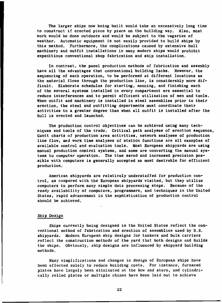
The larger ships now being built would take an excessively long timeto construct if erected piece by piece on the building way. Also, mostwork would be done outdoors and would be subject to the vagaries ofweather. Automatic equipment is not easily provided to build ships bythis method. Furthermore, the complications caused by extensive hullmachinery and outfit installations in many modern ships would prohibitexpeditious conventional shop fabrication and ship installation.
In contrast, the panel production methods of fabrication and assemblyhave all the advantages that conventional building lacks. However, thesequencing of each operation, to be performed at different locations asthe material flows through the production line, is considerably more dif-ficult. Elaborate schedules for starting, manning, and finishing eachof the several systems installed in every compartment are essential toreduce interferences and to permit efficient utilization of men and tools.When outfit and machinery is installed in steel assemblies prior to theirerection, the steel and outfitting departments must coordinate theiractivities to a greater degree than when all outfit is installed after thehull is erected and launched.
The production control objectives can be achieved using many tech-niques and tools of the trade. Critical path analyses of erection sequence,Gantt charts of production area activities, network analyses of productionline flow, and work time analyses of station functions are all examples ofavailable control and evaluation tools. Most European shipyards are usingmanual production control systems, and some are converting the manual sys-tems to computer operation. The time saved and increased precision pos-sible with computers is generally accepted as most desirable for efficientproduction.
American shipyards are relatively understaffed for production con-trol, as compared with the European shipyards visited, but they utilizecomputers to perform many simple data processing steps. Because of theready availability of computers, programmers, and techniques in the UnitedStates, rapid advancement in the sophistication of production controlshould be achieved.
Ship Design
Ships currently being designed in the United States reflect the con-ventional method of fabrication and erection of assemblies used by U.S.shipyards. Modern European ship designs for tankers and bulk carriersreflect the construction methods of the yard that both designs and buildsthe ships. Obviously, ship designs are influenced by shipyard buildingmethods.
Many simplifications and changes in design of European ships havebeen effected solely to reduce building costs. For instance, furnacedplates have largely been eliminated at the bow and stern, and cylindri-cally rolled plates or multiple chines have been laid out to achieve
22

essentially the same hull underwater body shape. Transom sterns replacedcruiser sterns with their difficult cant frames. Straight deck camber andno sheer have been specified, and many brackets have been eliminated.Dual purpose main and stripping pumps and piping systems have been in-stalled. Also, standard stiffeners have been purchased from outsidesources at lower cost, rather'than fabricated in the yard. These are onlya few examples of design alterations that simplify the shipbuilding proj-ect and make the ship more suitable for mechanized production yards.
The large size and simplicity of design of supertankers and largebulk carriers permit these changes to be implemented. Relatively simplehulls are fabricated of large flat steel panels and assembled as shell,decks, inner bottoms, and bulkheads. Diesel engines have little auxiliaryengine room machinery (compared to steam turbine powerplants), and theycan be prefabricated and installed in the ship in a few pieces. The loca-tion of machinery and outfit in one area aft permits the remainder of thehull to be erected after the machinery room is built.
These ship designs are particularly appropriate for construction inthe Arendal-type shipyard. Other modernized yards, such as B&W, do notbenefit as much from the engine aft-layout, since the machinery room canbe erected first, even if it is amidships.
The Arendal building dock with two stations, shown in Figure 4 maybe suitable for building of tankers and bulk carriers. However, otherships are more complicated and have outfit throughout their length, withinthe bottom, and on the upper decks. The FDL(X) ship is representative ofthe more complicated ship design that may be attempted in an Arendal-typeshipyard. The particular design of the FDL(X) would substantially deter-mine the layout of the modernized shipyard, even if modified to incorporatesome of the simplifications noted. Chapter IV describes the FDL(X) shipand its assemblies for mechanized production.
23

!V THE FDL(X) SHIP
The FDL(X) Description
The primary mission of the Fast Deployment Logistic ship in to oper-ate in a forward military area, carrying equipment and cargo in a condi-tion of readiness for rapid unloading in a friendly port or over a beach.The space requirements for stowing several landing craft and amphibiouscraft and a large number of wheeled and tracked vehicles govern the shipdesign. The landing craft must be able to float off, and provisions mustbe made for loading vessels by moving vehicles between decks or ramps tothe transfer area. The capabilities for unloading through side ports toa wharf, or over the side by the cargo derricks, were also specified FDLcharacteristics. Helicoptors to be carried aboard may use the main deckaft for flight operations and for loading small vehicles and palletizedcargo. A pallet lift and special holds were also specified.*
All of these specifications result in many special systems to be in-stalled aboard the FDL(X). For example, ventilation and dehumidifica-tion systems for the vehicle cargo decks are required to permit runningthe engines of the many trucks. A compressed air system for tire infla-tion extends throughout the cargo area, as do a motor gasoline supplyline from the ship's internal tanks and a fire-fighting system. Thelarge stern ramp and its complicated operating mechanism, ballast, anddewatering systems are also to be provided. Approximately 200 personnelare necessary to accomplish the vessel operation and vehicle maintenancefunctions, and accommodations are to be provided.
The FDL(X) preliminary design provided by the Bureau of Shipst de-scribed a ship with the following measurements: 640 foot-overall length,28-foot draft, 104-foot beam, 55-foot depth to the main deck, and approx-imately 28,000 long tons full-load displacement. The FDL(X) resembles anoversized regular Navy LPD of 17,000 tons displacement except the FDL(X)carries a small MSTS crew, has no armament, and can only accommodate asmall Army Vehicle Maintenance Unit and Navy Communications Unit.
The FDL(X) design studied in this report included gas turbine enginespowering an electric generator connected by cable to an electric motor for
* The general description adheres to the preliminary design specificationsprovided in the Ship's Characteristics Board Memorandum No. 69-65, SCBProject 720.66, dated June 11, 1965, Confidential.
t The drawing provided for this study was Bureau of Ships Plan No.PD-5804 dated July 15, 1965, "FDL, SCB Project 720.66-Hull Arrangement."
Preceding page blank 25

propulsion. Major auxiliary machinery to be installed would include ship'sservice generators, a distilling plant, air compressors, refrigeration andair conditioning plants, and machinery automation. These major installa-tions, and much of the minor hull machinery and outfit, can be built,tested, and delivered complete on skids or foundations. Major equipmenthas been assumed to be available in this condition in order to expediteship construction.
All of these FDL(X) requirements for machinery, hull engineering, andoutfit, are in distinct contrast to the relatively few equipments in-stalled in a bulk carrier or tanker ship. The many vehicle decks and ac-commodations alone far exceed the number of similar decks and spaces onthe largest commercial ship. Few ferry boats or ships have as much vehiclespace. For these reasons, the FDL(X) was divided into pieces that can beeasily fabricated and assembled and that permit simple installation ofmachinery and outfit.
A section is a portion of the ship that represents a vertical slicethrough the ship. In the FDL(X) ship shown in Figure 6, 16 sections havebeen used as the basic common denominator for ship structural assemblies;each section is approximately 40 feet or less in length. The length ofeach section reflects the bulkhead spacing of the FDL(X) design, and thestandard length of plates and shapes that can be purchased without incur-ring extra costs.
Assemblies are parts of sections. An assembly generally has the samelength as a section, but each assembly represents a separate lift from afabrication location in the main assembly building to a location on thehull in the building dock. There are approximately 90 assemblies in theFDL(X) ship when divided as shown in Figure 6.
The rationale for dividing the FDL(X) ship into these assemblies wasrather simple. In order to use the expensive building dock as intensivelyas possible, and thus to erect the greatest number of ships per year, thework to be performed in the dock should be minimized. Dock work is reducedby lifting the least number of assemblies to be joined, each of the largestpossible size. On the other hand, principles of structural integrity maylimit the use of the largest assemblies, since each assembly must have atleast one transverse bulkhead for adequate stiffness during lifting. Fur-ther, the total weight of the assembly to be lifted must be within thecrane lift capacity provided.
Figure 6 is a profile view indicating the locations where the FDL(X)ship has been divided into sections and (to a certain extent) into assem-blies. Such components as the stern ramp, boat davits, kingposts andmasts, and other structures have not been included in the sections.
The shading indicates the use of space along the centerline of theFDL(X) ship. The fuel tanks, machinery spaces, and cargo holds below thelowest vehicle deck, or sixth deck, are lifted as one assembly for eachsection. The wing-walls of this ship, like floating dry docks, contain
26

HisM
CCD
ca -
4A I&D
CA C -D
C.cm
_o C3
.. .. . .. . ....... .... ca
__ __n
~~44OD4 ___ __ Ui
.I.... ... .....
- Laiu'sE
44 k~ Sa
_ _ __...- ..
0
m-c
U-U

much outfit, and each side assembly is several decks high. Vehicle decksextend the length of the ship between the wing walls and are connected byramps. Sections 9 and 10 near the middle of the ship will be used assamples of the fabrication method and erection sequence.
Figure 7 is an exploded view of Sections 9 and 10 of the FDL(X) ship.The bottom assembly, BA, extends the full beam of the ship and up to thesixth deck, 32-1/2 feet above the base line. The weights of these bottomassemblies range from 152 tons * to 367 tons for the main motor rooms with-out the motors. The bottom assemblies are composed of four very largesubassemblies: the inner bottom and bottom shell, the side shell and sidetank bulkheads and deck overhead, port and starboard, and the longitudinalbulkheads and boat deck subassembly that is prefabricated upside down andhas an egg-crate structure similar to the inner bottom.
The next general class of assemblies is the side assemblies. Thelower side assembly, LS, extends from the sixth deck to the main deck,about 43 feet high. The upper side assemblies, US, extend 22 feet abovethe main deck of the ship. All side assemblies are narrow, generallyabout 16 feet in the beam dimension, and may be either 40 feet or 80 feetlong. The 80-foot side assembly was chosen in most cases to reduce thenumber of lifts into the dock, to permit the use of heavy lifts, and toincrease the amount of outfit installed in the side assemblies prior toerection on the ship.
The next class of assemblies is the vehicle decks, D. Vehicle decksvary as to their location throughout the ship, but generally can betermed the main deck, MD; the second deck, 2D; the fourth deck, 4D; andthe sixth deck. The vehicle deck at the sixth deck forms, however, thetop of the bottom assembly. Most vehicle decks are 72 feet wide and40 feet long, and may weigh about 40 tons.
Other assemblies in Sections 9 and 10 are the 01 deck, OlD, anothervehicle deck; and a deck house assembly, DH, consisting of the 02 deckand its overhead (the 03 deck) with the hotel spaces between them. Thedeck house assembly does not extend the full beam of the superstructure,but fits between the upper side assemblies, similar to a vehicle deck.
Figure 8 shows four typical assemblies and indicates more detail asto the structural content of each assembly. A deck house assembly, DH;a lower side assembly, LS; a bottom assembly, RA, and a vehicle deck, D,(inverted) are shown.
The weight and identification of all assemblies are shown in Appen-dix A. The installed small items such as hatch covers, masts, boat davits,and similar structures are not included in that table. The steel weightof each assembly was estimated from the scantlings of LPD-type ships ofsimilar design, and increased proportionally to the increase in ship
* All weight units in this report are short tons, unless otherwise spec-ified.
28

9-4p
I W I I I 1
U;I
z0
z
41C NC o .A: ýj cm l.a
CAB. 6" a.
-l ..D. cauh mctw =~ w' ccc NV)~~ be La U C .
= -J CL CDrCa _j am 101i. D
X~I-- 2c. ISA~~ U 0~~li~ L

Figure 8
TYPICAL FDL(X) ASSEMBLIES
DHDECK HOUSE ASSEMBLY(03 level omitted for clarity)
LOWER SIDE ASSEMBLY 4D, 2D, MD, OlDVEHICLE DECK(inverted)
BABOTTOM ASSEMBLY
SOURCE: Morris Guralnick Associates

Figure 9
ASSEMBLIES FOR FDL(X) SECTION 10
01 DK
MDj~Z)SOURE: MrrisGuranickAssoiate

IlkI
0 OA 0
u so
eee
0J 0
o 98090900
00 o. 0L L
Prcdn ag9ln

dimension as appropriate. Weights of major items of equipment were esti-mated and added in appropriate assemblies. The total assembly weight ofsteel and major equipment was increased a small amount depending uponthe assembly compartment usage, to obtain an estimate of the total assemblyweight.
The shading of assemblies in Figure 7 is gene,'ally indicative of thedifferent types of prefabrications that are needed in the different assem-blies. Large panels of stiffened plate, indicated by one shading, arerequired for the tank top and the deck houses. Another shade indicatesvehicle decks, D, almost 40 in total number. Yet another shade indicatesassemblies that consist of many smaller flat panels. Each of these dif-ferent size fabrications indicated by the shading are produced on a sep-arate production line. The darkest shaded panels are curved shell panels,which are made in a different production area.
Figure 9 is a detailed, exploded view of Section 10 of the FDL(X) shipstructure. The decks in the side assemblies at li.termediate levels betweenvehicle decks are shown. The primary longitudinal framing system, withlarge transverse web frames or girders at 10-feet spacing, are also illus-trated. Each assembly usually has four transverse girders. This con-struction system is useful in prefabrication of stiffened-plate panels,because the inherent structural strength of plates stiffened in bothdirections facilitates lifting panels to assemblies and erecting on theship.
Figure 10 shows deck arrangements for Section 10 of the FDL(X) design.The heads on the 01, main, and second decks, designated by a number 2 ina circle, are of identical external dimensions, except in the officers'stateroom on the 02 deck level. The location of bulkheads near each sec-tion joint permits outfitting to be essentially complete on the oppositeside of the bulkhead, if desired. The 80-foot side assemblies usuallyhave five to eight compartments and a through passageway on each deck.The side assembly of Section 10, shown on Figure 10, is mated with Sec-tion 9 for outfitting and erecting in the ship.
Appendix B lists the major equipment installed in each assembly andsubassembly of Section 10 of the FDL(X) design. The use of the compart-ments in this section has been almost completely assigned in the FDL(X)drawing and only two sections have more outfit in the sides than Sec-tion 10. The total amount of outfitting to be installed in each assembly,as illustrated by Section 10, is relatively small. Therefore, the great-est amount of work to be done in each assembly is also small and can beaccomplished in a reasonably short outfitting time.
34

V SHIPYARD LAYOUT
A perspective view of the shipyard, Figure 11, illustrates in con-siderable detail the many buildings and facilities of a conceptual ship-yard design. The building dock, outfitting wharf, and activity in theassembly building are prominently shown. Gantry cranes in the main aisleand the bridge cranes over the outfitting area are also shown. The threemain shipyard areas are identified.
The first of these areas is the steel storage and processing area.It contains the facilities that store, prime paint, cut, and bend most ofthe 8,500 tons of steel used in the ship.
The second area, the main assembly building complex, is the locationof panel production lines and halls where subassemblies and assembliesare fabricated. In this yard layout, five stations of the building dockare located inside the main assembly building.
The third shipyard area is for outfitting and warehousing. This isa building situated to serve ship assemblies being outfitted, to provideeasy azcess to the ship as it is pushed out into the building dock, andto serve the ship in the final outfitting at the high wharf after it hasbeen launched.
An office building, a cafeteria, a fabrication shop for large pile,and the dock pump house are also shown in the foreground of the perspec-tive drawing.
This chapter describes the functions and operations to be accom-plished in building FDL(X) ships, beginning with an assumption of manu-factured or purchased materials. The next three parts of this chapterdescribe in detail the three working areas shown in Figure 11: (1) thesteel processing area; (2) the subassembly and bottom assembly areas ofthe main assembly complex; and (3) the outfitting area of the assemblybuilding and outfitting shop areas and the erection of the ship in thebuilding dock. By following this sequence of description, the flow ofmaterials may be traced into the shipyard, through prefabrication, assem-bly, and outfitting, and into the ship.
Manufacture or Purchase
The guidelines for this study were briefly stated in Chapter I. Thepostulated, mechanized shipyard would be devoted entirely to performing.those manufacturing operations that are peculiar to ship building. Theyard would not provide specialized manufacturing facilities that are
35

ICE
00
cec
U.U

available in other production plants, especially since the utilization ofthese facilit 4es would be low if geared only to the FDL(X) productionrate. For example, 12 FDL(X) propellers required per year probably couldnot justify the cost of the foundry and machining equipment needed fortheir production.
In FDL procurement, many of the bidders currently own and operateshops for production of many items, including such commonly manufactureditems as ventilation duct dampers and screens, furniture, watertight doorsand hatches, and ladders. Other equipment less frequently manufacturedin U.S. shipyards, and also assumed to be purchased, includes electricalswitchboards and panels, cable stuffing tubes, winches and windlasses,waveguide, and stainless steel sinks.
Adhering to the guidelines set for this study, a list of purchasedmaterials and a list of items to be manufactured by the postulated ship-yard were developed for the FDL(X). These lists are in Appendix C and werederived from the Proposed Material Ordering Guide for the LPD 9 class ofships. No attempt was made to estimate the size or capacity of installedcomponents.
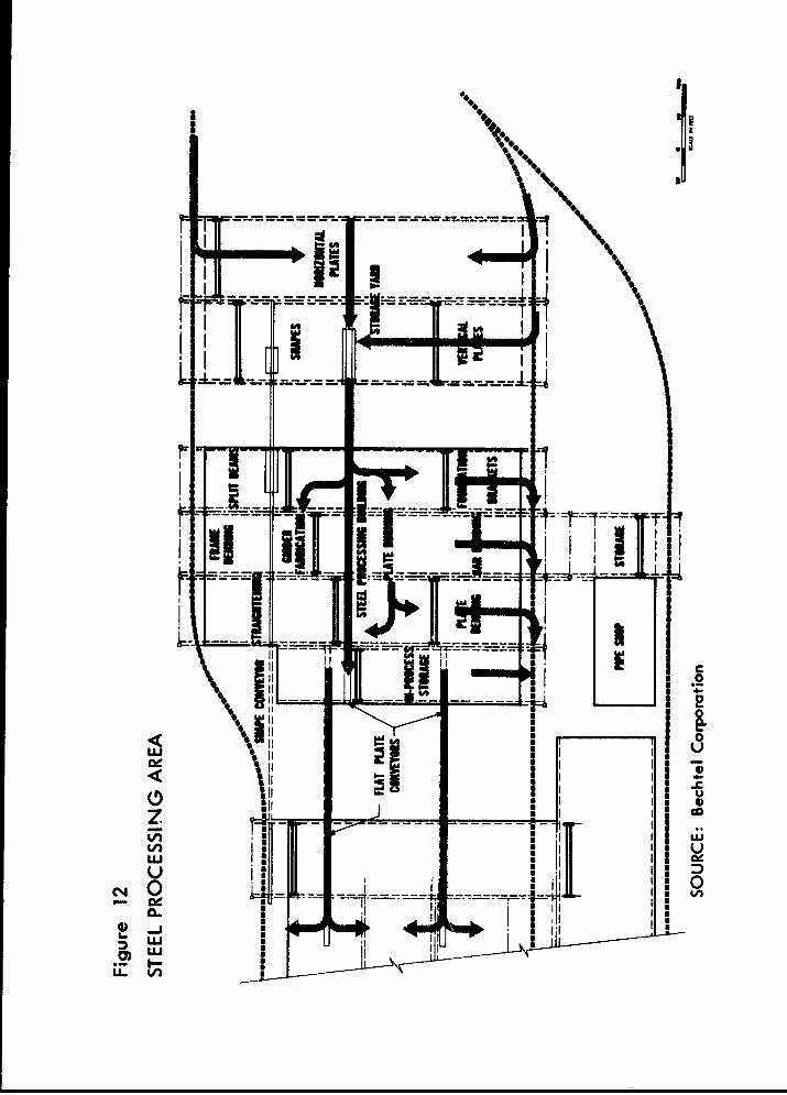
Steel Processing Area
The steel processing area shown in the plan view of Figure 12 can bedivided functionally and geographically into three spaces: a storage yard,a steel processing building, and an in-process storage area.
Storage Yard
Within this area, three separate sections are designated for flat
plates, shape stock, and miscellaneous storage. Materials are generallydelivered to the yard by rail car and can be unloaded by overhead bridgecranes at either end of the storage yard. All cranes in this area are15-ton capacity with magnetic grips, and about 130-foot span. Steelplates for the FDL(X) ship are stored horizontally in the flat plate sec-tion, stacked one upon the other in piles by size and oriented parallelto the tracks. Shape stock is stored on vertical ladder-type stanchionsand handled by a bridge crane with fork lift-type fingers. The miscel-laneous yard is used to store heavy and uncommon plates stacked verticallybetween posts and handled by clamps.
The crane operators pick stock from a given location and transfer itin sequence of production to one of two conveyor processing lines, onefor plates and another for shapes. A location near the head of the shapeconveyor line is set aside for cutting and welding operations on shapestock, to reduce scrap losses. Ends of shapes are cut square, shapes arewelded into a continuous length, and shape stock is re-cut to piecelengths specified for a particular use later in the fabrication process.
37
*#4 I I
-- -
IL
Along the plate conveyor within the storage yard are vertical sandblast-ing and prime paint spraying facilities and a roller/leveler.*
Steel Processing Building
A large number of machines, storage areas, and conveyor handlingequipment are located in the steel processing building. Cutting is doneon automatic parallel and irregular (profile) cutting machines controlledby tape or optical tracers, which can also mark plates for further bend-ing operations. Conveyors are used for the transportation of flat materialbetween crane bayst and to feed machines. For transfer of irregularlyshaped material, and for all movements along the three bays of the build-ing, 15-ton overhead bridge cranes are used. In addition, smaller cranesare positioned at appropriate locations to serve individual processingmachines.
The shaded arrow of Figure 12 shows the general flow of plates throughthe steel processing area. In a bay at one end of the building, brackets,clips, and foundations are cut and welded; bent girders are fabricated inthe middle bay; and plates are rolled at the other bay. Plates that arefabricated into flat or curved girders are fabricated between the conveyorlines. After fabrication, if the plate stock is bent to the extent thatit cannot be carried by a conveyor, it is carried by bridge cranes outthrough the doors at the side of the building and by special vehicles tothe main assembly buildings. Bent shapes also move out the side of thebuilding and are also moved by vehicles. Otherwise, conveyors move flatplate stock to the in-process storage area and straight shapes to thetransfer area.
Process Storage Areas
The in-process storage area for plates serves as buffer storage tosmooth out imbalances in the production flow. Also, the storage area craneprovides a capability to lift plates in a particular order onto a conveyorthat handles material to the panel lines of the main assembly building.
The in-process storage area for the panel stiffeners and girders isin the transfer and jig loading bay adjacent to the building where theseshapes are used.
* The need for a plate leveller is more apparent in Europe than in the
United States. However, shipfitting problems are reduced if flat plateis available for processing after transportation, and purchase costsmay be reduced if levelling is done by the shipyard.
t The term bay describes the space in a building between the row of col-umns that usually carry at least one set of rails for overhead cranes.
39

Main Assembly Building
Figure 13 shows the layout of the main assembly building, includingthe panel production lines, subassembly, outfitting, and bottom assemblyhalls, and the part of the building dock that is inside the building.
Panel Production
Five production lines have been designed for the fabrication of flatpanels and decks. The general technique and sequence used for manufactureof deck assemblies and panel subassemblies is common throughout all of thelines, and a typical panel line will be described to indicate the degreeof analysis performed.
Each of the lines has a number of fabrication stations, and specificoperations are accomplished at each station. A continuous fabricationconveyor moves intermittently and stops for the same period at each sta-tion. Plates are received from the plate conveyor in a particular orderat the first station as they are to be used in the production line. Thefirst operation to be accomplished in each production line is to weldautomatically a number of steel plates to one another.
Meanwhile, at the transfer area, shape stock is being loaded intopredetermined spacing in a positioning jig, one for each panel line. Thepanel is then transferred on the wide fabrication conveyor to the nextstation on the line, where shapes are positioned on the plates by the jigcarried by overhead crane. In the next operation and location on theassembly line, the stiffeners are welded to the plates, again by automaticmachinery. Further down the line, additional stiffening members, orgirders, are added to the panel or assembly, if needed.
At another station, brackets and foundations are welded for ventila-tion ducts, for electrical cable runs, panels, and lights, and for auxil-iary machinery. Then the fabrication conveyor passes into a curtainedspace where cleaning and spray painting may be accomplished safely.
Then operations have been completed on one side of the panel, turn-ing the assembly over may be necessary for back welding operations, suchas finishing the vehicle lashing sockets. The turnover is accomplishedby a pair of 50-ton bridge cranes in the invert and transfer bay at theend of the panel lines. From the arrival of steel plate in the yard untilthe completion of flat panel fabrication, the orientation of plates andmany shapes has not changed, which has simplified the material handlingproblems. The number of conveyor stations depends on the stop time, whichin turn reflects the amount of work to be done. The large lines advanceone station each eight hours. This description is typical of the depthof analysis performed to estimate the buildings and numbers of equipmentin this yard layout.
40

- - - - - - - - - - - - -
an I .ao
on II I 1 0_j - IL- -
Can
Ua
Ig Ii
00 'ON* w in"O "mot I m
ca 0

Curved panel subassemblies, such as shell panels, are fabricated inthe bay between flat panel lines and the bottom assembly area of the mainassembly building and are supplied by bent plates and shapes transferredby truck or rail cars from locations at the sides of the steel-processingbuilding. Curved stock is carried by a pair of 50-ton bridge cranes fromthe storage location at the end of the rail line to a specific locationwithin the subassembly area where curved shell panels may be fabricatedin place.
In contrast, the flat panel production lines carry fabrications fromone station to another by materiel transfer mechanisms, while the curvedpanels are fabricated in place on flexible or adaptable jigs that arepreset to the plate contour required.
After fabrication, curved shell plates are lifted to the transferbay at the ends of the production lines. There, curved side shell panelsare placed over flat decks, the bulkhead panels are joined, and the sideshell tank subassembly is sent to the bottom assembly area. A few curvedshell panels are conveyed directly to the bottom assembly area for fab-rication of the bow sections.
Assembly
Depending on the use of the flat panels, they may be transferred toa storage location for lift directly onto the ship, as is the case withvehicle deck assemblies. Or, the panels may be moved out of the buildingsthrough the doors at the ends of the inverting and subassembly bays. Flatpanels may be stacked on trailers and stored until needed. Or, the panelsmay be transferred by the pair of 90-ton bridge cranes to locations wherebox-type upper and lower side assemblies will be fabricated, sometimes onlarge weldment positioners. In the subassembly bay, panels are joined topermit down hand, semi-automatic welding, if possible. Assemblies arethen finished in an upright position in the next bay adjacent to the out-fitting shops where outfit installation is started. The arrows in Fig-ure 13 represent the flow of typical panels as they are fabricated andmoved for further assembly or outfitting.
A long aisle for fabrication and outfitting of bottom assemblies isshown in Figure 13. The bottom assembly aisle continues over the fivecovered stations in the building dock, and it is served by the same cranesthat serve the bottom assembly fabrication areas. Eight locations arereserved for the fabrication of bottom assemblies, or half of the totalnumber in the ship. The bottom shell is fabricated in place on specialjigs designed for the FDL(X) ship cross-section, except for five flat-bottom midship sections. Fabrications of egg crate subassemblies arereceived from a location at the end of the aisle. Last, side shell tanksare placed on the inner bottom, and piping, machinery foundations, andauxiliaries installed, and painting begun. The pipe shop adjoining thisarea provides most of the large ballast, fuel, and other types of pipingthat are used in the bottom assemblies. The fabrication time for each
42

bottom assembly is not constant, but depends on the amount of work to bedone. After the azsembly is completed, it is lifted, together with itsjig, into place on the ship at the proper station in the building dock.
The building height required to clear the cranes is rather low formost of the stations in the flat panel and deck assembly lines. The hookheight is approximately 20 feet for bridge cranes of 15-ton capacity in
the flat panel assembly areas. But 60 feet to the hook of two 50-toncranes is needed for the curved panel assembly area for crane loads to
clear fabrications in process. The main aisle of the main assembly build-ing is somewhat taller in order to clear assemblies under construction andthe hull being erected: hook heights of 80 feet in the 200-ton gantrycranes, and 100 feet for the bridge cranes are the minimum necessary.
Outfitting
The overall concept of this yard provides for installation of out-fitting in assemblies before they are lifted into place in the building
dock to obtain substantial savings in outfitting manpower. To reduce menand material movements, the outfitting shop has been situated directlyadjoining a bay reserved for outfitting assemblies in the main assemblybuilding, as shown in Figure 14, which partially overlaps the area shownin Figure 13. This area is particularly well located for easy access dur-ing outfitting of the more complex hotel, office, and operational spaceson the FDL(X) ship. Specifically, the assemblies that are fabricated and
outfitted in this area are the upper and lower side assemblies, and the 01and 02 deck deckhouse assemblies. Space has been allocated along the wall
of the main assembly building for six 80-foot long side assemblies and allfour deckhouse assemblies. These outfitted assemblies can be lifted aboardthe vessel at building dock stations B through E, by the outfitting bay
125-ton cranes, operating independently of the main aisle cranes.
The material flow of outfitting items is shown by shaded arrows inFigure 14. Material arrives at the warehouse either by truck or rail andis transferred from the warehouse through the outfitting building, or if
necessary around the outfitting building to specific locations directlyinto the ship, either in the building dock or at the outfitting wharf.
The warehouse has been designed with a powered tote-track for smalltrucks and fork lift equipment on the ground floor, and with a bin con-veyor, servicing small parts stock on the upper floor, that starts andends on the lower floor.
Much of the activity to be accomplished within the outfitting build-ing should be organized along production line requirements rather than
along shop or craft bases. Thus, rather than advocating a machine shopas such, production items, the work-force, and their equipment should
be allocated so that specific repetitive items and subassemblies can befabricated in production lines and transferred directly to the particularassembly in which they are to be located. For example, the FDL(X) designN•ould permit production lines for heads, to be installed in the ship
43

-' -- - - - -
z0 ~ ~ ~ :4
I I I i
i R fu iL

complete with plumbing and wiring, and only needing to be connected to
the rest of the piping and electrical systems. Sufficient machinery hasbeen provided to accomplish all of the operations expected in the outfit-ting shop.
Figure 14 also shows the two level luffing cranes that serve thebuilding dock and the outfitting wharf for installation of masts, sternramps, and outfit. The top of the fitting-out wharf is at a high level,approximately the elevation of the main deck of the FDL(X). The fourthdeck side ports of the FDL(X) are nearly the same level as the test shopsand offices on the mezzanine of the wharf. The wharf level at the surfaceis sheltered, is an extension of the outfitting shop bays and has craneand truck service. A vehicle ramp provides access from the surface eleva-tion to the upper level.
Erection
The following will describe the FDL(X) ship in the erection processand its movement out of the building dock within the main assembly build-ing. Figure 15 shows the FDL(X) ship at a particular stage in its con-struction called period nine, as an example of the assembly sequence.There have been eight pushes of the ship out of the building prior to thisparticular stage in its erection, and the ninth push work is about to takeplace. A small crew is called at the end of work shift 27 on the shipfor two to four hours to operate the hydraulic pushing rams and installthe new sets of sliding ways for the next erection operations.
The five 40-foot long stations in the building dock, lettered Athrough E are shown along the bottom of Figure 15. Although there aresome rather minor deviations to the ise of each of the stations, Figure 15also indicates the station wher,. each different assembly type is placed.Bottom assemblies are generally lifted by the 200-ton travelling gantrycranes in a lengthwise direction from their fabrication area in the maincrane aisle to the building dock at Station A. Lower side assemblies aregenerally lifted by the 125-ton bridge cranes to stations B and C whenthey are 80 feet in length, and to station B in the cas6-of 40-footlengths. The vehicle decks are moved to the assemb' area for additionof pillars, then stored at the head of the building dock, and finallylifted on at station C. Deck house assemblies and upper side assembliesthat are fabricated and outfitted in the outfitting area are lifted by apair of 125-ton, 160-foot span, double-hook bridge cranes into the build-ing dock and are placed on the ship at stations D and E.
During this ninth period, the lower side assemblies (both port andstarboard) of sections 9 and 10 have been lifted in at stations B and C;the bottom assembly of section 11 has been placed at Station A; the lowerpart of the stack and the 02 deck assembly of section eight--and the ramps
also associited with section 8--have been lifted in at Stations D and E;
and the fourth, second, and main deck vehicle decks of section 9 have
been erected at Station C, In the next period, section 10 vehicle decks,
and section 12 bottom assemblies will be placed aboard.
45

INC-
M 04
44-
UjUIcm
_ LU
-It
0
U.. L.. (0
Figure 16 shows a part of the erection schedule for the FDL(X) ship,including the period of time immediately preceding, during, and after thatillustrated on the previous Figure 15. (The complete assembly scheduleis shown in Appendix D.)
The schedule in Figure 16 shows the five stations in the buildingdock along the left margin, and the passage of time across the chart ina horizontal direction. The schedule includes only the three time periodbnumbered eight, nine, and ten, and 7 work shifts numbered from 23 to 29.The point in time shown on the previous Figure 15 is at the end of the9th period and shift 27.
This schedule was developed for each of the 90 lifts of assembliesor main equipment that are required to construct the FDL(X) ship. Eachlift was analyzed by estimating the crane time and the welding time re-quired for the assembly. The crane time includes the time required tohook up, lift, move, set down, and, where necessary, to hold the assemblywhile it is sufficiently welded to the adjoining r•cructure for the craneto release it. The welding time is the minimum required before the nextassembly can be lifted into place, or before the ship can be pushed. Forexample, during the ninth period, the critical time results from certainoperations accomplished in sequence by the outfitting bay cranes. First,the cranes must lift the port or the starboard section 9-10 lower sideassembly into Stations B and C, ond hold it until it can stand by itself.Then, the crane returns to pick up the other lower side assembly and liftsit into place. Both lower side sections must be welded substantially intoplace before a vehicle deck can be fitted between them. Then the threevehicle decks of section 9 are lifted into Station C, in sequence fromthe fourth deck through the main deck, and each is tack welded before thecrane can lift the next deck. The erection schedule was derived in thisamount of detail to lay out the shipyard as a balanced, workable concept.The number of relatively complex assemblies to be lifted aboard indicatesthat five covered stations--approximately one-third of the ship's length--may be desirable in the building dock to expedite erection of the hull.
Operations for gantry cranes that lift the bottom assembly need notbe scheduled as carefully during period nine as the outfitting bay bridgecranes. In certain other periods, the large gantry cranes are heavilyused and may determine the rate of erecting assemblies. If more craneswere provided over the building dock stations, different erection se-quences would become critical, and the total time between ship pusheswould be only slightly decreased, since pushing is not done during a workshift.
If the ship were not moved in the building dock but built in place(as at Burmeister and Wain's), crane service must extend a longer dis-tance, but the space required for building assemblies and panels in themain assembly building would be the same as shown before. In addition,covering the entire building dock to provide shelter over all the erec-tion stations would be expensive; however, the cost of the pushing mecha-nism would be saved. Burmeister and Wain's single building dock is well
47

Figure 16
FDL(X) SHIP ERECTION SCHEDULE (PARTIAL)
PERIOD VIII IX X
SHIFT 23II 2 25126127 28II 9
STATION
C B
E
SOURCE: Bechtel Corporation

separated from the assembly hall, but is laid out without cover. Manyshipyards admit to about 15 percent loss of productivity when working inthe open under normal weather conditions compared with indoors; undervery poor conditions, work must stop. Therefore, by covering 200 feet ofbuilding dock, the postulated yard is able to erect all assemblies undercover.
Completion
As the ship is extruded stern first from the main assembly building,the hull machinery, electrical and electronic equipment, and outfit canbe connected and completed. The stern ramp and masts can be installedby the portal cranes. The ship is accessible through the stern gate andthe side ports. A hammerhead crane may be placed on board for liftinglight tools and equipment. After the jigs are removed, hull painting maybe accomplished from a pair of powered rolling stages. Installation ofrudders, shafts, and propellers may be expedited with special cranetrucks, although about 30 days time is available co accomplish thesetasks before launching.
After launching the FDL(X) by flooding the building dock and remov-ing the gate, the ship is towed to the outfitting wharf where the finaltests are made.
The total time for fabricating an assembly and installing outfitvaries for each assembly, depending upon the complexity of the assembly,the amount of outfit, and time and place of erection in the ship. Forexample, the time available for assembly of panels and installation ofoutfit in deck house assemblies is 40 days prior to erection in the ship.Approximately two to eight diys after erection of the deck houses, theship is floated and moved to the outfitting dock for completion.
The time available for installation of outfitting in the upper andlower side assemblies varies from 3 to 20 work shifts, more time beingallowed for difficult machinery compartments at the outfitting buildingarea. After erection in the ship, at least 14 work shifts are availablebefore the ship is floated, and more shifts can be worked at the outfit-ting wharf prior to sea trials.
The bottom assemblies are in fabrication prior to placing the firstsections of each ship in the building dock. The motor room bottom assem-blies of section 6 may be fabricated and outfitted in about 25 workingshifts prior to erection in the building dock, and an equal length of timeis available before launching to complete the motor roobi installation.
In summary, the total time available to install machinery, electri-cal equipment, and furnishings is expected to be adequate for orderlycompletion of the FDL(X) shortly after launching. Allowing time fortesting and sea trials, each FDL(X) should Oe delivered prior to launchof the subsequent ship. Therefore, only one berth has been provided atthe fit-out wharf.
49

Shipyard Layout
Figure 17 is the complete yard layout and includes some of the otherperipheral buildings and activities that have been included to completethe conceptual yard design.
The rail lines shown on the layout of Figure 17 serve both sides ofthe main assembly complex, both sides of the steel processing area, andpossibly the steel scrap yard. Some of these lines can be used for trans-fer of materials between buildings; other spurs can be used for deliveryof equipment and supplies from outside the shipyard. Especially heavyequipment, such as the main drive motors for the FDL(X) ship, can belifted directly from a rail car into the main assembly building.
The conveyors that carry material from the steel processing buildingto the main assembly building are underground to allow a road to pass be-tween the buildings. Additional space has been left for possible futureexpansion of buildings between steel storage and steel processing areas,and between steel processing and main assembly buildings. The steel pro-cessing ani pipe shop buildings m.iy also be extended at the ends, andanother bay may be added to the side of the main assembly building.
This layout probably is not an optimal arrangement, but simply onealternative selected to provide all the necessary production equipmentand space, linked by suitable handling equipment along material flow linesfor FDL(X) construction. Other layouts and equipments can be conceivedthat should also achieve the same purposes, and alternatives should beevaluated carefully before proceeding into construction of a new ship-building plant.
50

.1IL
i i ' I -
F hullCIL06\
VI CONCEPTUAL SHIPYARD DESIGN AND CONSTRUCTION
The facilities of the mechanized shipyard are designed to accommo-date, in an economic and flexible manner, the mechanized manufacturingoperations, storage, and administrative functions required for the con-ceptual layout described. To optimize the facilities plan was not fea-sible within the scope of work and study time allowed. The conceptuallayout represents the first approach to the problem of balancing con-flicting production requirements and facility costs, and it is only oneof many possible alternative layouts. Other plans are expected to besuperior.
The cost estimates and construction schedule were developed on theassumption that all preliminary industrial engineering and naval archi-tecture has been completed, that the site has been selected, and that allequipment requiring a long lead time has been ordered promptly to avoiddelay in completion of construction. This program would produce shipyardfacilities for a minimum capital cost and on a time schedule establishedto minimize cost. Final shipyard design, equipment procurement, and con-struction proceed on an overlapping and, at times, simultaneous schedule.
The order of magnitude cost estimates shown on Table 1 are based onfactoring similar types of construction, and not on a detailed take-offmaterial quantities from engineering drawings. Prices for some of theproduction machinery were obtained from manufacturers. Contingency allow-ances of varying amounts have been included, depending on the engineeringdetail available and the potential variation that could develop. Thecosts shown are realistic estimates for the scope of work described, atcurrent 1965 prices without escalation for future price increases. Con-struction wurk is assumed to be done on a straight-time basis withoutacceleration of equipment procurement.
Computer and communications equipment and gas storage facilities areassumed to be furnished under supply contracts, and therefore their costsare not included. Engineering design costs are included in each item forfinal working drawings, calculations, and procurement specifications onthe assumption that preliminary fa..ility engineering has been completedand a set of design criteria has been previously established.
The capital improvements and equipment included in the cost estimateare only those needed to produce ships of the general size and descriptionof the FDL(X) but does not include special tooling or special test equip-ment designed exclusively for use on a particular ship design, or generalship checkout and test equipment. Also excluded from the cost are spareparts for equipment, hand tools, and automation equipment not describedin this report for production lines.
Preceding page blank 53

Table 1
MECHANIZED SHIPYARD COST ESTIMATE
Cost(thousands
Buildings Dimensions of dollars)
Service buildings 80,000 sq. ft. $ 1,900
Plate and shape storage 600Steel processing 520' x 400' 2,900
Pipe fabrication and storage 300' x 100' 500Panel production area 560' x 440' 5,300
Main assembly including transferbays 1,100' x 160' + 400' x 40' 10,200
Warehouse and maintenance areas 440' x 240' 1,500
Outfitting shops 400' x 360' 4,100
Subtotal $27,000
Docks
Dry dock 8,300Outfitting wharf 2,700
Subtotal $11,000
Materials Handling Equipment
Conveyors 2,100Overhead cranes 7,500
Mobile equipment 1,400
Subtotal $11,000
Production Machinery
Mechanical and electrical 27,000
Site Development 4,000
Total $80,000
Source: Bechtel Corporation
54

The considerable investment--$80 million--in this type of yard indi-cates intensive operation is economically desirable to reduce the amorti-zation burden per ship to the minimum. A two-shift operation of the one-dock yard would therefore appear preferable to a two-dock yard operatedfor one shift if production of up to 12 ships a year is required. Someof the equipment would not be operated on the second shift. Should a pro-duction level between 12 and 24 ships a year be needed, the cost of atwo-dock yard is estimated to be $144 million, roughly an 80 percent in-crease for those facilities needing duplication.
Sites Conditions and Development
As shown in Figure 18, the facilities for a shipyard with one build-ing dock can be built on a rectangular site with about 3,500 feet inlanddepth and a waterfrontage of about 1,750 feet, an area of approximately140 acres. Land acquisition costs are not included in the estimate be-cause of wide price variations and the possibility of making lease arrange-ments for land. (In order to provide sufficient space to double the sizeof the facility, the waterfront should be doubled to nearly 3,500 feet onthe initial purchase.) Fencing of the two-dock yard perimeter is includedin the one-dock yard estimate.
The site topography is assumed to be a few feet above sea level,fronting navigable water with an average tidal range. The existing beachwas assumed to slope from the shoreline to a depth of 35 feet at a dis-tance of 700 feet offshore. After construction of the cofferdam for thebuilding dock and the bulkhead for the outfitting dock, dredging to adepth of 35 feet is included for a waterfront distance of 1,200 feet.Subsoil is assumed to be permeable alluvial deposit, with a lower clay-bearing stratum. Soil-bearing values permit the use of spread footingsfor minor buildings and the construction of floor slabs on grade, butmajor buildings require piling to clay. Significant variations in sitedevelopment and dock costs could occur with different site conditions.
After clearing and removal of topsoil, rough grading for adequatesurface drainage is assumed to be balanced cut and fill without importa-tion or dumpirg. .reparation of subgrade soil for areas to be paved orused for railroads and yard storage is assumed to require a layer of com-pacted granular fill. Drainage is in open ditches, except where pipeculverts are needed for crossing roads and railroads.
A heavy-duty highway and a railroad line are assumed to be availableat the site boundary. Extension of the railroad is assumed with rail at100 lbs. per yard and a maximum curvature of 160. Barge and towing serv-ices are presumed to be available at the wharf. Roads are generallyheavy-duty asphaltic concrete paving, 24 feet wide with minimum 50-footradius bends. Parking for 1,500 cars is included on the basis that shiftsare staggered sufficiently to avoid doubling the space. All paving costis estimated at $200,000.
55

a I LIl U.L.z I.-c zo0<4 Oi; --ai =;i,- A
0. .>
La .u Zo t- czo L
10 U.1 Z ?I-. ~>Ja ~ < ,. -1 zSo< ZZ 00< czJ 0 a
LU~- w
ti~z _o
10L 1In C4 C4 4 tý o r i
@) I 4U
0 0"__gx
i-
4-___

A theoretical site on the Middle Atlantic to Northeast Coast areawas selected as being conservative from a cost standpoint, i.e., moreweather protection may be needed there than on the Gulf Coast, and becausethe Arendal principle is designed for ship erection under cover. Designfactors assumed the following:
Wind: Maximum velocity--l00 mph
Rainfall: 30 inches per year average
Snowfall: 40 inches per year average
AirTemperatures: Maximum summer 100°F
Minimum winter 10OF
Humidity: Average 80%
Earthquakes: Seismic probability--Zone 1, minor damage
The site is assumed to be within commuting distance of both construc-tion and shipyard labor, and the immediate surroundings are assumed to becompatible with shipyard operations.
Sanitary and storm water drainage is assumed to be collected, treated,and disposed of through yard systems independent of outside facilities.A gravity collection system for treatment of sewage in a packaged aerationunit and an effluent pump station are located near the center of the water-front.
Utility supplies are assumed to be available at the property linewithout charges for extension. Within the shipyard, main utilities needto be distributed, and costs are estimated from the descriptions thatfollow:
A main power transformer station converts and meters the incomingoverhead electrical supply for underground distribution to the yard. Lo-cal transformer and switchgear stations are provided to supply powercircuits for welding machines, motor centers, and lighting. A ring watermain supplies all process and domestic requirements and fire protectionneeds. A ring main supplies natural gas to each building for space andfurnace heating. Air compressors and after coolers with distributionsystems and equipment are located in each main building, and intertiesare provided to adjacent buildings for flexibility in case of breakdown.Liquid oxygen is assumed to be stored at a central location, where it isvaporized and distributed by pipe to each building.
The cost estimate included an acetylene gas manufacturing plant ata central location, with gas distributed at low pressure to the buildingswhere it is needed for burning operations. Alternate gas systems could beprovided when the total cost of purchases and operations may be more eco-nomical than an acetylene gas system.
57

Yard maintenance and protection vehicles costs are included in thesite development category.
Docks
The building dock is designed to provide a clear space 750 feet long,120 feet wide, and 35 feet deep below high water. Pumping equipment isprovided to dewater the dock in eight hours after launching; however, the$400,000 cost is included under production machinery. Capstans, winches,and bollards to assist in maneuvering ships out of the dock are includedin the cost estimate. The gate is a floating caisson type, with controlledballasting to maintain trim in transit, and cost $900,000 installed.
Construction is planned inside a dewatered excavation protected onthe water side by a steel sheet pile cofferdam. The dock is assumed tobe a fully relieved, reinforced concrete structure, with drains below thefloor and behind the walls to prevent the build-up of hydrostatic pressurewhen empty.
The pushing mechanism is used to extrude the ship from the assemblybuilding into the uncovered portion of the building dock as the ship erec-tion proceeds. Erection of the next section of the ship is begun by lower-ing the appropriate bottom assembly and jig onto the sliding ways atStation A of the building dock within the assembly building. Thirteenpush operations are required for the FDL(X) vessel erection, and each pushmoves the erected portions of the ship a total of 40 feet. After eachpush operation, sections of sliding ways are placed on the five rows offixed ways at the vacated Station A. Both the fixed and sliding ways areequipped with teflon pads at their bearing surfaces to reduce friction andthereby minimize the force required to extrude the ship.
The pushing mechanism employs a hydraulic system consisting of five300-ton jacks supplied by a common header, two high-pressure positive dis-placement pumps, an oil reservoir, and suitable piping and valving to per-mit ejection and retraction of the Jack rams. The hydraulic jack cylindersabut a large reinforced concrete mass at the head of the building dock,and the ends of the rams are attached to a strongback which evenly dis-tributes the pushing force to the ends of the five sliding ways. Hydraulicjacks with 12-inch diameter cylinders require a maximum oil pressure ofapproximately 5,500 psi to develop the maximum thrust. A 10-gpm pumpwill push the ship at a rate of about four inches per minute.*
Stability considerations for the hydraulic rams may limit the lengthof stroke of the rams to about 10 feet. i£ter each 10-foot push, there-fore, the rams must be retracted, l)-foot sections of sliding ways inserted
* A hydraulic pushing mechanism is employed at the Arendal yard of GUta-verken, which claims to have patents on the operation. The extent ofthese claims, or details of the Arendal mechanism, are not known.
58

and secured to previously installed sliding ways, and then the push canbe resumed. Four separate operations are therefore required to accomplishthe total 40-foot length of push.
The cost of the pushing and sliding mechanism unique to the Arendalprinciple was estimated at $1 million.
The outfitting dock superstructure is a composit., construction ofprecast and prestressed concrete beams and columns, with pured-in-placeconcrete deck slabs. The lower dock level is supported on prestressedconcrete piling with a pile bulkhead wall, backfilled with spoil from thebuilding dock excavation. Shock absorbing fenders, mooring bollards,traveling crane tracks, and floodlighting systems are among the equipmentinstalled on the outfitting wharf.
Buildings
The types of building construction assumed for the shipyard costestimate are typical of heavy manufacturing plants in the United States.The number of buildings is limited to as few separate units as possible,each having as much potential for expansion and rearrangement of produc-tion equipment as can be provided economically. The three basic build-ing types are manufacturing facilities, outfitting shop and warehouse, andadministrative offices.
The manufacturing buildings are multiple-bay, welded steel-framestructures that support overhead bridge cranes and steel deck roofs withbuilt-up composition roofing. Metal siding above 10-foot high, precastconcrete sill-walls provides a low maintenance enclosure for the largespace required. Doors are power-operated, steel roll-up type where prac-tical, or vertical-rising or horizontal-sliding doors, depending on theavailability of door parking space and door size. Gravity roof vents aresupplemented with fans where necessary to disperse heavy fume concentra-ticas. Windows are limited to a band above the sill-wall, to minimizeconstruction and maintenance costs, and to avoid sun dazzle and confusingshadow patterns. Gas-fired unit heaters are provided at areas usuallyoccupied by personnel. A reinforced concrete floor slab provides supportto all equipment and manufacturing operations, except a few heavy machinesneeding individual pile foundation.
Lighting is by high level fixtures providing a low overall intensityof illumination, with local lighting mounted where needed on columns andproduction equipment.
Utility distribution systems and electrical sub-stations are locatedoverhead. Motor control centers, racks of welding machines, offices, andstorage are located between the columns. Electrical system costs withinbuildings are included in the production equipment category.
59

The outfitting shops and the warehouse building are generally similarto the manufacturing buildings just described, except for their lowerheight and lighter construction. At the end of the outfitting shops adja-cent to the assembly outfitting area, a multilevel gallery permits accessto each of the deck levels inside the side assemblies and deck houses ofthe ship. These galleries are of varying widths to permit overhead craneservice to reach each level. The outfitting shops and warehouse buildingsare insulated and heated throughout, and are brightly illuminated in com-parison with the steel processing and main assembly buildings.
The office and cafeteria buildings are of precast concrete floor andwall panel construction. Integrated air conditioning and lighting systemsare provided for efficient working conditions in the office building for
administrative and engineering functions, and for modern first aid andcafeteria space.
Materials Handling Equipment
The panel lines in the main assembly building are served by heavyindustrial bridge cranes or monorail hoists over the small panel produc-tion lines, and all five flat panel production lines are wheel-type con-veyors. The flat panels are pulled along the wheel conveyors by chaindrives, and the total cost of these movable panel lines is $1,200,000.
Unique crane coverage is provided over the building dock and extend-ing into the assembly building. Two nesting traveling gantries of200-ton capacity provide a combined 400-ton capability to lift heavy bot-tom and bow assemblies. In addition, each gantry is provided with twoindependent trollies so arranged that 200-ton assemblies may easily beinverted, thereby permitting down-hand welding operations. These cranesmay cost nearly $1 million each.
Industrial bridge cranes are provided in the outfitting shops andextend under the high level outfitting dock, and enable transfer of out-fiL to the ship through hatches by the level-luffing portal whirly craneabove. A freight elevator is also provided for material movement to the
high level outfitting dock, and another to the bottom of the building
dock.
Conveyors are provided in the warehouse, and fork lift trucks andother mobile equipment operate in this area aiLd throughout the yard.
The material handling cost category includes the cost of installationand appurtenances. The cost of the gantry crane tracks in the building isestimated at $140,000.
Production Machinery
The requirements for production machinery and equipment in the mech-anized FDL(X) shipyard concept are estimated from the work to be accom-plished at each work station on each production line. Equipment is
60

generally sized to handle the largest plate, shape, shaft, or assemblythat may be needed on an FDL(X)-type ship. For the outfitting shop inparticular, the numbers of machines needed were crudely estimated, as in-sufficient time was available during this study to define each operation.
The quantity and cost of machine tools is based upon conventionalshipyard tooling data, modified to reflect the most modern automaticmachines available. The use of tape-controlled and similar advanced ma-chinery should permit machine time savings in the expected range of one-third to one-fifth the operating time of conventional machine tools,especially for multiple ship production. Fewer operators and less build-ing floor space are needed, at a higher initial cost per automated machinein contrast to standard machinery.
The quantity and cost of many types of major machinery have been sum-marized in Appendix E, and the total cost is over $10 million. The costsshown are for the purchase cost only at factory or U.S. entry port, in-cluding freight and duty. Foundations, installation, run-in, and similarexpenses have not been included in Appendix E, but are included in thetotal cost estimate for production machinery. The cost of small machinesand equipment, and of a great variety of other miscellanecus equipment andaccessories, was added to the major costs calculated at length.
The cost of electrical power and control equipment and wiring withinbuildings was estimated at $4.5 million. The platens for welding may costover $1.2 million.
The European shipyards are notably well equipped with machinery,especially developed for shipbuilding. The foreign manufacturers of ma-chinery that have provided data and prices to this report are included inAppendix F, noting the manufacturer's U.S. representative in severalcases.
Design and Construction Schedule
Figure 19 shows a shipyard design and construction schedule for theone-dock yard. The basis for determining the start date is the date ofproduction contract award. Land acquisition is assumed to have progressedto permit site development to commence four months after the start date.Additionally, all preliminary ship design and production engineering workshould be complete, facility design criteria should be established priorto the start date shown, and major equipment should be ordered suffi-ciently in advance to be on-site when needed for installation.
A lead time of six months prior to the start of building and dockconstruction is estimated for the detailed construction engineering.Design proceeds concurrently with construction until the conclusion ofthe major design effort at the end of eighteen months. Follow-on engi-neering is needed to verify that equipment design is compatible withspecifications and installation requirements.
61

Figure 19
SHIPYARD DESIGN AND CONSTRUCTION SCHEDULE
FIRST YEAR SECOND YEAR THIRD YEAR
CONSTRUCTION ENGINEERING
I m 44SITE DEVELOPMENT & UTILITIES
DOCKS
BUILDINGS
CRANES
EQUIPMENT
RUN-IN
TOTAL 10% 75% 15%EXPENDITURE %
COMMITMENT _ 45% 50% 5%
MAJOR EFFORT (INCLUDES RETENTION)
- FOLLOW-UP
SOURCE: Bechtel Corporation

The total shipyard construction elapsed time of 30 months assumes anormal work week without overtime. The principal items on the shipyardconstruction critical path are building dock construction and procurementof structural steel for the main assembly building.
Expenditures and financial commitments will not be distributed evenlyduring the progress of the work, but will require commitment of approx-imately 45 percent of the total cost during the first year, although ex-penditure may be only 10 percent of cost. Retention of 10 percent ofcontract amounts until the end of the guarantee period, for assurance ofsatisfactory construction, iicreases the amount of expenditures in thelast six months above that expected on a uniform basis.
Near the end of the construction period, partial occupancy of certainportions of the shipyard should be arranged to permit a smooth take-overby the operating personnel and enable ship production work and jig prep-aration to be started immediately after final acceptance of the yard.The steel processing area could be completed at the end of 24 months andthe subassembly area, including panel lines, at the end of 26 months.
63

VII CONCLUSIONS
Suitability of Production Line
The principles of assembly line production are feasible for buildingFDL(X) ships in the conceptual, mechanized shipyard described in thisstudy.
Production lines were developed for fabrication and preparation ofshapes and plates, and for stiffened plate or panels. Flow lines andwork stations were established for fabrication of steel hull assembliesand installation of their outfit. Even the erection of the assemblieswas specified at certain locations in a repetitive sequence, and meetsthe criteria of a production line process. Further, production linesare considered to be practical for preparation of outfit, such as piping,ventilation ducts, heads, electrical cable harnesses, ventilation machin-ery rooms, foundations, and similar items. The shipyard mechanical andelectrical equipment requirements for FDL(X) production were derived froma cursory analysis of the jobs to be done, and production equipment wasthen located at each station of the many production lines. The use ofjigs and special tooling to expedite repetitive manufacture of similarproducts was specified for most production lines. The possibilities ofautomating many steps in the production lines are apparent, much more sothan in conventional shipbuilding,
Early installation of outfit, hull engineering, and machinery in theassemblies was arranged to minimize labor and material movements and ex-pedite ship completion.
Ship design changes to facilitate production line fabrication andassembly are desirable,
The duties of each employee could be assigned on the basis of thework station requirement, rather than on craft or union bases, and shouldresult in a less labor-intensive plant.
The interrelationship of various steps in the production line willundoubtedly require elaborate and comprehensive production control andindustrial engineering, both of which are possible with currently avail-able techniques.
Application of the Arendal Erection Principle
The orientation of this study toward the use of the Arendal principleof erection as stated at the outset of this report does not necessarily
Preceding page blank 65

imply that this particular method is the most effective way to buildFDL(X) ships, First of all, the Arendal yard was designed primarily forthe construction of tankers and bulk cargo ships, The Arendal managementstates that other types of cargo ships can be produced in their yard.But for erection of the FDL(X), substantial deviation from the Arendalyard design has seemed appropriate.
The Arendal erection principle has the basic advantage that expensivecovered or enclosed ship erection area is reduced to a minimum. Work inthe assembly areas and in the building dock is concentrated at two indoorerection stations that can be used to full efficiency at all times. Thedisadvantages of the Arendal erection principle are that a complex push-ing mechanism and sliding ways are necessary to extrude the ship, andthat a complex system of doors is necessary to enclose the ship Thetotal cost for these two items was estimated at over $1.1 million.
The number of building dock stations in the FDL(X) yard concept hasbeen increased from two to five because the FDL(X) is R relatively compli-cated ship, and to attempt to build it in two stations would result in anunnecessarily long span of time to complete the entire ship. A very cur-sory analysis indicated that to build the FDL(X) ship using two stationsmight take 50 percent longer than with the five station building dockshown in this report. Five stations cannot be claimed as the best way tobuild the FDL(X) ship under the Arendal principle; more or fewer stationsmay be optimal, but insufficient analysis time was available to optimizethe yard concept.
An appraisal of what might be termed the opposite of the Arendalprinciple is desirable to place the erection principle in perspective.Where the number of stations inside the building dock equals the numberof sections in the ship, the entire building dock would be enclosed, andthe ship would be built in place, In this case, the cost of the addi-tional building length would be considerably higher--estimated at $2 mil-lion plus the cost of cranes--but the complex pushing mechanism and slid-ing ways would not be required.
The Arendal principle of both pushing the ship and covering manystations in the building dock may be the most economic way to erec+ shipsfor some number of enclosed building dock stations, Enclosing one, five,ten, or all of the sixteen sections of the building dock,may be the mosteconomical design.
In this study the Arendal erection principle was to be applied toFDL(X) erection no matter how much the principle may be questioned. Thepushing and erection system was to be utilized in the concept until con-cluAve evidence could be found that the Arendal principle was not appro-priate for the FDL(X) ship. This conclusive evidence has not been dis-covered, and the Arendal erection principle may be appropriate for theFDL program.
66
Shipyard Flexibility for Construction of Other Ship Types
The concept of a mechanized shipyard for FDL(X) production appearsto be a rather flexible yard for production of other ship types, The longmain assembly aisle served by 200-ton gantry cranes is capable of liftingmany types of assemblies into any one of the five work stations in thedock. The wide span permits the transverse cranes to move materials andassemblies over wide areas, both on the outfitting assembly floor and intoone of the five stations in the dock. The availability of five erectionstations, rather than two, provides flexibility to erect each assembly atmany positions in the building dock within a limited time range, Thesteel processing area a,,d building has a general design that would beefficient for many ship types. Except for the selection of the tonnagecapacities and physical sizes of steel processing machinery, the capabil-ity of this building is quite general. Substantial space has been leftaside for future expansion in two areas between buildings and at the sidesof many buildings. Finally, the building dock dimensions are adequate forbuilding ships up to the maximum size that can pass through the PanamaCanal. A large proportion of all cargo ships anticipated for U.S. ship-building in the near future could be built in the conceptual shipyard.Considerable production flexibility can be obtained at little penalty toFDL costs.
In conclusion, an outline of one conceptual shipyard in which FDLships might be produced in a new and mechanized yard in the United Stateshas been described. The FDL(X) design is adaptable to mechanized produc-tion, and can be manufactured with advanced production line techniquesto attain low shipbuilding costs in steel prodaction. The plant shownin this report, with a capital cost of $80 million, has a capability offrom 6 to nearly 12 ships a year, depending on whether a one-shift or atwo-shift operation is used, and these production rates can be doubledagain by duplicating Acst of the yard.
67

APPENDIXES
Preceding page blank /

ý- t I'. .10 " 1r-4
14 w . tt
P4 M 4 -4 -
0-4 to o
00 -444 -1414 0 P-4 10 0 0 '4
0 C4
z 4 0 0
Ca 1'40 W w o w C43~c'-4 %.0
(a to
go~ 0 0)
-4 -
1 0 0 0 0
I ~ C') C'
00;4)
m O t L .4 '. o ' 4k.1z 4.4 U) c
*0 0 S
0 14 4*. C' &') kC')4 o $4 .
41 4) k 0 z 1 ) 1 401 14 H A 0.. c
0 ) C -014 144.1 0 14 0
w) 14~: ( o , 0 9 W
Pr ce in pag bl n 71 . 4 1

o -e
t o
'M.0
N'-' N
13 N esN 0 0 N 0
0..ý
dI ý
ý4 04 41I ~
0S03 0 ,.
11 4 4 A U.
14 0 V
z4 1 A. %
14 -A 44 4a
A 0
04 9
0 63
bd
0

41.4 N 0
.0~~ ~ U 10 4(A 0 * * . 0 4)
0 0 o 0'1
414A~~c )0 C
41 ~ 0 0
041*
£ ~ ~ ~ t 41 1 1s o 0 4
1. 9 .4.4 -
0.
91 :.1 C, .4 04
.4
S 41 01 fr- 0 a
4 1 .4 4 41 41 41 41 ~
i4;.~, .A
4.4 4 414.4 4O 41 4U 0~ 04
~ 0.. 4441 Ch.
14N

Appendix C
FDL(X) MANUFACTURE OR PURCHASE LIST
Manufacture only those items which:
1. Form the ship's structure (including its structural subdivisions).
2. Comprise the piping and duct systems (not including the associate
equipment).
Major items for manufacture are:
ManholesVentilation ductsPiping (not including pumps, heat exchangers and valves)
Shell platingShaft fairwatersDouble platesSkegRudderLongitudinal and transverse framing
Stanchions of nonstandard pipesizeFlangesDecks, platforms, and flatsDeck longitudinalsTransverse deck beamsAll machinery, electrical and other equipment foundationsTrunks and enclosuresStructural bulkheadsKing posts and support framesMasts
Purchase all items of equipment, outfit, furnishings, and allowance:
Machinery Equipment
Quantity Description
2 Propulsion gas turbines2 Propulsion generators2 Propulsion motors3 Propulsion excitation M-G sets2 Propulsion shafts (rough)
Preceding page blank 77

Quantity Description
2 Propellers4 Ships' service diesel generators1 Emergency diesel generator1 Distilling unit2 Auxilliary boilers2 Helicopter and interior communications motor generators2 Distillate fuel transfer pumps2 Distillate fuel booster pumps2 Distillate fuel tank stripping pumpsI Distillate fuel transfer (emergency generator) pump1 Lube oil transfer (gas turbine) pump1 Lube oil transfer pump2 Lube oil service (motor) pumps1 JP-5 service pump1 JP-5 transfer pump1 JP-5 str~pping pump4 Salt water circulating pumps1 Gasoline pump1 Gasoline salt water compressor pump2 Priming (for JP-5 service) pumps4 Fire pumps2 Portable water pumps1 Portable water priming pumps2 Hydraulic (gas turbine start) pumps3 Bilge and ballast2 Air conditioning compressors2 Air conditioning chill water pumps2 Sanitary flushing pumps2 Refrigerated compressors2 Ship's service air compressors2 Ship's service air receivers2 High pressure air compressors10 High pressure air flasks18 Dehumidification units
As required Air conditioning recirculation fansAs required Dehumidifying recirculation fansAs required Ventilation fansAs required Machinery space fans
3 Foam proportioners2 Diesel oil filter/separator2 Diesel oil purifier2 Lube oil filter/separator (propulsion motor)1 JP-5 purifier1 JP-5 filter/separator1 Gasoline filter/separator2 Lube oil cooler (propulsion motor)4 Lube oil cooler (ships' service diesel-generator)1 Fresh water drain cooler
78

Electrical - E Outfit - 0 Machinery - M
Lighting fixtures Sideport doors Piping elbows and
Monorail bends
Electrical switchboards Pallet conveyors Ramp winchesand panels, switchgearRectifiers, adbttgeary Pallet LD/UNLD. Posi- Hatch and stern gate,Rectifiers and battery tioner and horizontal hydraulic operatingcharging systems gearconveyorCompass, gauges, etc. Overhead monorail hoists Air motors
Alarms, announcing, Stores and ammunition Capstans and mooringindicator telephone handling equipment winchessystems hnln qimnsFork lift trucks Anchor windlass,Motor control equipment anchor and chain
Radar and radio equip- Pallet transporters FAS saddle winchment aiid waveguide Windows and wipers Rudder stock and pro-
Landing craft dollies peller shaft, stern
Refrigerator doors tubes
26-ft MWB and 33-ft Steering gear-
lifeboats and davits complete
Accommodation ladders Bearings
Access doors, hatches, Exhaust silencers
and scuttles Plumbing fixtures
Furniture: office, Valves and operatingstateroom, wardroom, mechanismshotel Purifiers, filters
Ladders (piping and ventil-at in
Shelves and bins; ammu- ng)
nition stowage fittings
Rigging
Insulation
Deck covering
Dumb waiter
Heating and refrigera-tion coils
Shop equipment
Vehicle lashings andsockets
Convectors, unit heat-ers, fans
Source: Morris Guralnick Associates.
79

II
7 B
I x--IT*
C3 ~
cc cc---------------------------------------
______
a
ua.
wt
Prcein pag bln

Appendix E
MAJOR SHIPYARD MACHINERY
Number Unit Size Price
Steel Processing Area
1 Vertical plate shot blast $ 80,0001 Vertical plate paint primer 70,0001 Horizontal plate roller leveler 197,0001 Shape shot blast 80,0001 Shape paint primer 70,0003 Parallel plate cutting machines 135,0003 Irregular plate cutting machines 600,0004 Small plate strippers and tracers 108,0001 40-ft side plate roller 1,500 ton 543,0001 40-ft hydraulic press 1,800 ton 360,0001 9-ft end plate roller 800 ton 89,0002 40-ft plate press/flangers 1,000 ton 300,0001 Plate bender/press 400 ton 50,0001 Plate bender/roller 250 ton 83,0001 Plate shears 40-ft x 7/8-in. 48,0001 Plate shears 15-ft x 5/8-in. 29,0002 Plate stamping machine 100 ton 78,0003 Frame benders 200 ton largest 200,0002 Beam splitting burners Large 52,0002 Edge planes 98,0004 Plate notchers Largest 93,0001 Frame bending furnace 27,0002 Girder welding machines 230,000
Total $3,620,000
Panel Production Lines and Main Assembly Building
36* Automatic single fillet welding machines $ 223,000123* Automatic double fillet welding machines 1,440,000
87* Automatic butt fillet welding machines 575,00016* Automatic vertical slag welding machines 262,000-- X-Ray equipment shop 320,000
Total $2,820,000
Preceding page blank 83

Number Unit Size Price
Transportation Equipment
4 Straddle carriers 30 ton $ 42,0008 Straddle carriers 15 ton 120,000
42 Fork lift trucks 51-ton largest 235,00020 Flat bed semi-trailers 25 in. 250,000
1 Flat bed semi-trailers 250 in. 47,000
5 Tractors 50,000
Total $ 724,000
Pipe Shop
1 Pipe bender 12-in. max. $ 88,0001 Pipe bender 10-in. max. 55,0002* Pipe benders 8-in. max. 76,0002* Pipe benders 4-in. max. 22,0007* Pipe benders 2-in. max. 49,000
12 Induction heaters 120,0002 Milling machines Large and small 31,000
Total $ 441,000
Machine Shop
5 Drill presses 6-ft. x 17-in. largest $ 48,0002 Threading machines 3-in. largest 44,0005* Power saws/shears 81,0003* Grinders, external cylindrical 16-in. x144-in. 105,000
largest3* Grinders, miscellaneous Vertical rotating 111,000
36-in. largest3 Presses 500-ton largest 200,0003 Drilling machines, radial 10-ft. largest 140,0003 Gear hobbing machines 36-in. x1S-in largest 86,0004 Engine lathes 48-in. x48-in largest. 350,0002 Turret lathes 3-1/2-in. largest 102,0004 Milling machines, vertical 285,000
and horizontal3 Planers and shapers 93,0003 Boring mills, vertical and
horizontal 555,000
Total $2,200,000
84

Number Unit Size Price
Miscellaneous
4 Sheet metal-press brakes, roll- $ 60,000ers, and shears
20 Electrical automatic cable reels 100,000
Total $ 160,000
* Includes units located elsewhere.
Source: Stanford Research Institute.
85

Appendix F
MACHINERY MANUFACTURERSTHEIR U.S. REPRESENTATIVE, AND THEIR PRODUCTS
Manufacturer Product U.S. Representative
Ingenjbrsfirma HEBE AB RollersStorgatan 19, ConveyorsOrebro, Sweden
Kjellberg-Eberle, GmbH Plate cutters Linde Co.Hanoverland Strasse 197-205, 270 Park AvenueFrankfort am Main, Germany New York 17, New York
ESAB Profile cutters National Cylinder Gas Co.Frankfort am Main Welders 840 N. MichiganGermany Chicago, Illinois
GAG Optical markers Ampower Corp.Grandveg 56-58 50 Broad Street2 Lokstedt New York, New YorkHamburg, Germany
Gesellschaft Anzeichen Gerite MBH Optical marketsHamburg 54 Plate cuttersLokstedt, Germany
Hugh Smith and Co. (Possil) Ltd., Plate & frame benders Strachan-Mackoe Corp.
Glasgow N. 2, Shears 70 HudsonScotland Planners Hoboken, New Jersey
RollersPresses
Wagner A/G, Rollers Girard AssociatesDortmund Shears P.O. Box 415Germany Chambersburg, Pa.
Maschinenfabrik Froriep, Rollers Cosa Corp.Rheydt Benders 405 Lexington AvenueRhineland, Germany New York, New York
Wilhelmsburger Maschinenfabrik, RollersHinrichs & Sohn
Geesthacht BeiHamburg, Germany
Preceding page blank 87

Manufacturer Product U.S. Representative
Ursviken Mekanisha Verstads A/B, PressesUrsviken ShearsSkelleftel, Sweden
Herkules-Werk Frame benders Bohn Engineering andGmbH Machinery Co.Wetzlar, Germany 1485 Bayshore Highway
San Francisco, California
Upton, Bradeen and James18067 Wyoming AvenueDetroit 21, Michigan
Bronx Engineering PressesStourport,England
A. B. Hagglund and r;6ner WeldersBox 5164Gothenburg, Sweden
Pullmax (Kaiser Pullmax AB) Profile welders Kaiser Steel Inter-
Vasagatan 20 Plate production line national DivisionVasterls, Sweden Oakland, California
Eckold Metal formers Bohn Engineering and342q St. Andreasberg- Machinery Co.
Spe.-.luttertal 1483 Bayshore HighwayOberharz, Germany San Francisco, California
Pines Co. Pipe bendersAurora, Illinois
Krupp-Ardelt GmbH, C:anes Carl G. Brimmekamp &2940 Wilhemshaven Co.Germany 582 Market Street
San Francisco, California
Kampnagle A/G CranesJarre Strasse 26Hamburg 39, Gerrany
Weinmann A/C Heavy lift trailers Walter Schimpf
6775 K~nigsbofen, Kolb-rmoorer Strasse 32Baden, Germany Bad ,..bling, Germany
s8