by Leonid Dorf - Los Alamos National...
38
by Leonid Dorf Presented at Plasma Physics Summer School Presented at Plasma Physics Summer School August 2, 2006, P August 2, 2006, P - - 24 Plasma Physics Group, LANL 24 Plasma Physics Group, LANL k B E e – i + P-24 Plasma Physics Special thanks to : Hall Thruster eXperiment at PPPL (go to URL: htx.pppl.gov), and Jahn, R. G. and Choueiri, E. Y. (2002). Electric Propulsion. In Encyclopedia of Physical Science and Technology, 3rd Edition (Academic Press, San Diego), Vol. 5, p. 125.
Transcript of by Leonid Dorf - Los Alamos National...

by Leonid Dorf
Presented at Plasma Physics Summer School Presented at Plasma Physics Summer School August 2, 2006, PAugust 2, 2006, P--24 Plasma Physics Group, LANL 24 Plasma Physics Group, LANL
kB E
e– i+
P-24Plasma Physics
Special thanks to: Hall Thruster eXperiment at PPPL (go to URL: htx.pppl.gov), and Jahn, R. G. and Choueiri, E. Y. (2002). Electric Propulsion. In Encyclopedia of Physical Science and Technology, 3rd Edition (Academic Press, San Diego), Vol. 5, p. 125.

Electric propulsion (EP) devices utilize a constantly renewable on-orbit resource (electric power from solar arrays or a nuclear source) to minimize the consumption of non-renewable on-board propellant. The EP techniques group broadly into three categories: electrothermal propulsion, wherein the propellant is electrically heated, then expanded thermodynamically through a nozzle; electrostatic propulsion, wherein ionized propellant particles are accelerated through an electric field; and electromagnetic propulsion, wherein current driven through a propellant plasma interacts with an internal or external magnetic field to provide thrust. Such systems can produce a range of exhaust velocities and payload mass fractions an order of magnitude higher than that of the most advanced chemical rockets, which can thereby enable or substantially enhance many attractive space missions. The attainable thrust densities (thrust per unit exhaust area) of these systems are much lower, however, which predicates longer flight times. This talk will focus mainly on the electrostatic and electromagnetic propulsion techniques, also called plasma propulsion, due to the nature of the propellant. Principles of operation, key issues, and commonly used diagnostics are discussed in detail for such complex devices as magnetoplasmadynamic thruster (MPDT), pulsed plasma thruster (PPT), ion thruster (IT), Hall thruster (HT), cylindrical Hall thruster (CHT), VASIMR, and others. Key physical questions specific to Hall thrusters are also elucidated.
Abstract
Outline
Basic Concepts and Equations of Propulsion
Types of Plasma Propulsion
Electrothermal propulsion
Electrostatic Propulsion: Ion Thrusters
Electromagnetic Propulsion: MPD, PPT, TAL, VASIMR, HT, CHT
Hall Thruster Diagnostics: plume divergence, electron temperature, etc
Anode Sheath in Hall Thrusters

Rocket Equation
Vjet - V ∆m M - ∆m
Time = t Time = t + ∆t
M(t)V(t) V + ∆V
Momentum Conservation: P (t) = Const
Px(t) = M V
Px(t + ∆t) = (M – ∆m) (V + ∆V) – ∆m (Vjet – V) = M V + M ∆V – ∆m Vjet
∆m = µ ∆t
X
M dV/dt = µ Vjet – Rocket (Mescherskii’s) Equation
V(t) = Vjet ln[M0 / M(t)] – Tziolkovskii’s Formula

Electric Propulsion = Large Exhaust Velocity
32 /fuel sat jetM M P S Vη≈
2 /flight jet satt V M S Pη≈
Earth
Jupiter
Vjet (plasma) ~ 10 – 100 km/s >> Vjet (chemical) ~ 3 km/s
Interplanetary Missions:
Higher Vjet LESS FUEL (but longer time)
S
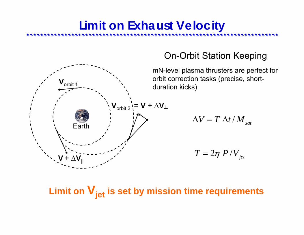
Limit on Exhaust Velocity
Vorbit 1
V + ∆V||
Earth
Vorbit 2 = V + ∆V
On-Orbit Station KeepingmN-level plasma thrusters are perfect for orbit correction tasks (precise, short-duration kicks)
/ satV T t M∆ = ∆
Limit on Vjet is set by mission time requirements
2 / jetT P Vη=

Types of Electric Propulsion
1. Electrothermal propulsion, wherein the propellant is heated by some electrical process, then expanded through a suitable nozzle
a. Resistojetsb. Arcjetsc. Inductively and radiatively heated devices
2. Electrostatic propulsion, wherein the propellant is accelerated by direct application of electrostatic forces to ionized particles
a. Ion Thrusters (IT)b. Field Emission Electric Propulsion (FEEP)c. Colloidal Thrusters
3. Electromagnetic propulsion, wherein the propellant is accelerated under the combined action of electric and magnetic fields
a. MagnetoPlasmaDynamic (MPD) Thrustersb. Hall Thrusters (HT)c. Pulsed Plasma Thrusters (PPT)d. Inductive Thrusters
1960 1970 1980 1990 1994 1998
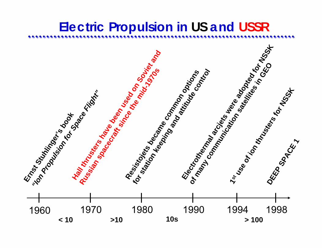
Electric Propulsion in US and USSREr
nst S
tuhl
inge
r’s b
ook
“Ion
Prop
ulsi
on fo
r Spa
ce F
light
”
Resi
stoj
ets
beca
me
com
mon
opt
ions
for s
tatio
n ke
epin
g an
d at
titud
e co
ntro
l
Hall t
hrus
ters
hav
e be
en u
sed
on S
ovie
t and
Russ
ian
spac
ecra
ft si
nce
the
mid
-197
0s
Elec
troth
erm
al a
rcje
ts w
ere
adop
ted
for N
SSK
of m
any
com
mun
icat
ion
sate
llite
s in
GEO
1st us
e of
ion
thru
ster
s fo
r NSS
K
DEEP
SPA
CE 1
< 10 >10 > 10010s

Electrothermal ResistojetHeat is transferred to propellant (hydrazine) from some solid surface, such as chamber wall or heater coil
Power level: 750 WattsThrust level: 300 mNExhaust velocity: 3.5 km/sEfficiency: 80 %

Cathode (emitter) Anode (nozzle )Tangentialgas flow
Propellant (hydrazine) is heated by an electric arc driven through it
Power level: 1.5 kWThrust level: 200 mNExhaust velocity: 5 – 6 km/sEfficiency: 40 %
Electrothermal Arcjet
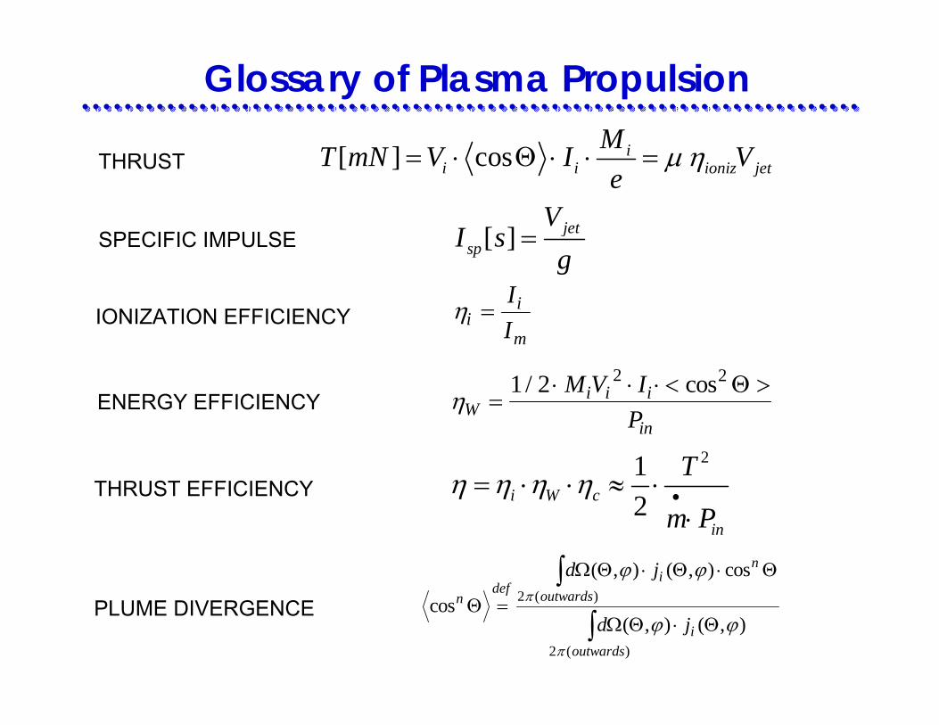
Glossary of Plasma Propulsion
[ ] cos ii i ioniz jet
MT mN V I Ve
µ η= ⋅ Θ ⋅ ⋅ =THRUST
SPECIFIC IMPULSE [ ] jetsp
VI s
g=
212i W c
in
T
m Pη η η η •= ⋅ ⋅ ≈ ⋅
⋅
IONIZATION EFFICIENCY
cos
( , ) ( , ) cos
( , ) ( , )( )
( )
ndef
ioutwards
n
ioutwards
d j
d jΘ
Ω Θ Θ Θ
Ω Θ Θ=
⋅ ⋅
⋅
∫
∫
ϕ ϕ
ϕ ϕπ
π
2
2
ηii
m
II
=
ηWi i i
in
M V IP
=⋅ ⋅ ⋅ < >1 2 2 2/ cos Θ
PLUME DIVERGENCE
ENERGY EFFICIENCY
THRUST EFFICIENCY
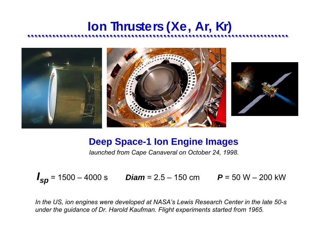
Ion Thrusters (Xe, Ar, Kr)
launched from Cape Canaveral on October 24, 1998. Deep Space-1 Ion Engine Images
Isp = 1500 – 4000 s Diam = 2.5 – 150 cm P = 50 W – 200 kW
In the US, ion engines were developed at NASA’s Lewis Research Center in the late 50-s under the guidance of Dr. Harold Kaufman. Flight experiments started from 1965.
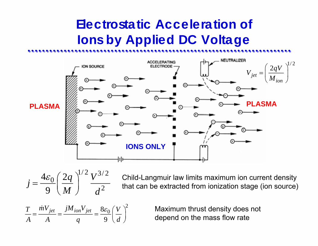
Electrostatic Acceleration of Ions by Applied DC Voltage
1/ 2 3/ 20
24 29
q VjM d
ε ⎛ ⎞= ⎜ ⎟⎝ ⎠
Child-Langmuir law limits maximum ion current densitythat can be extracted from ionization stage (ion source)
PLASMA PLASMA
IONS ONLY
208
9jet ion jetmV jM VT V
A A q dε ⎛ ⎞= = = ⎜ ⎟
⎝ ⎠
1/ 22
jetion
qVVM
⎛ ⎞= ⎜ ⎟
⎝ ⎠
Maximum thrust density does notdepend on the mass flow rate

Key Issue of Ion Thrusters
Accelerator gridUpstream side
normal
normal
damaged
damaged
Accelerator gridDownstream side
normal
damaged
Screen gridDownstream side
Soulas, G. C., “Improving the Total Impulse Capability of the NSTAR Ion Thruster with Thick-Accelerator Grid Ion Optics,” IEPC-01-081
Y. Hayakawa, S. Kitamura, and K. Miyazaki. Endurance Test of C/C Grids for 14-cm Xenon Ion Thrusters. AIAA 2002-3958
Grid erosion due to ion bombardment limits thruster lifetime

Ion Thruster Diagnostics
(Non-Intrusive )
Laser-Induced Fluorescence –for measurements of ion velocity and energy
Laser Interferometry –for measurements of electron, ion, and neutral densities
Spectrographic analysisof quartz crystal microbalances and fused silica samples placed in the plume –for determining the content and origin of the non-propellant flux coming out (erosion assesment)
Schematic of the cw diode laser system(NASA GRC)
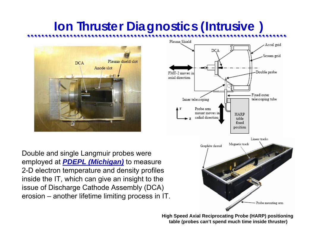
Ion Thruster Diagnostics (Intrusive )
High Speed Axial Reciprocating Probe (HARP) positioning table (probes can’t spend much time inside thruster)
Double and single Langmuir probes wereemployed at PDEPL (Michigan) to measure2-D electron temperature and density profilesinside the IT, which can give an insight to the issue of Discharge Cathode Assembly (DCA)erosion – another lifetime limiting process in IT.

E&M Propulsion: MPD ThrustersI sp = 1500 -8000 sec Power: 200 kW – 1 MW
Efficiency > 40% Thrust Density: 105 N/m2
Princeton 100 kW-class Lithium Lorentz-Force Accelerator (MPD-T)
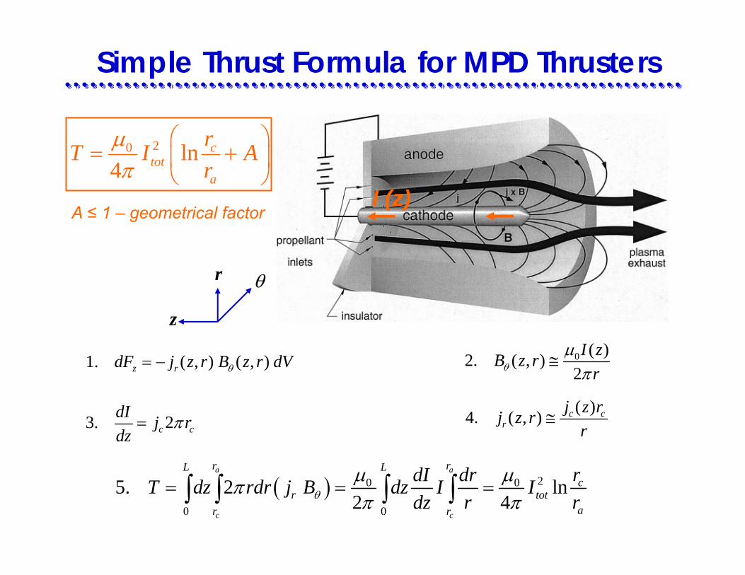
Simple Thrust Formula for MPD Thrusters
I (z)
r
z
θ
1. ( , ) ( , )z rdF j z r B z r dVθ= − 0 ( )2. ( , )2I zB z r
rθµ
π≅
3. 2c cdI j rdz
π=( )4. ( , ) c c
rj z rj z r
r≅
( ) 20 0
0 0
5. 2 ln2 4
a a
c c
r rL Lc
r totar r
dI dr rT dz rdr j B dz I Idz r rθ
µ µππ π
= = =∫ ∫ ∫ ∫
20 ln4
ctot
a
rT I Ar
µπ
⎛ ⎞= +⎜ ⎟
⎝ ⎠
A ≤ 1 – geometrical factor
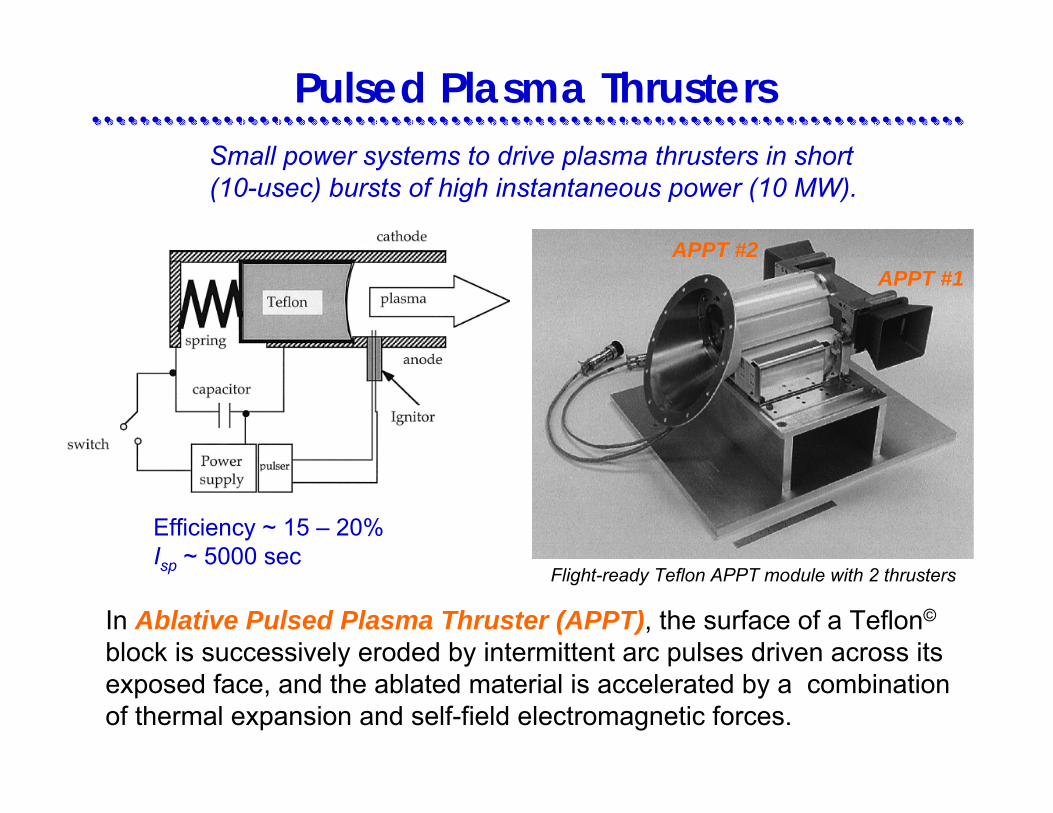
Pulsed Plasma Thrusters
In Ablative Pulsed Plasma Thruster (APPT), the surface of a Teflon©
block is successively eroded by intermittent arc pulses driven across its exposed face, and the ablated material is accelerated by a combination of thermal expansion and self-field electromagnetic forces.
Efficiency ~ 15 – 20%Isp ~ 5000 sec
Small power systems to drive plasma thrusters in short (10-usec) bursts of high instantaneous power (10 MW).
Flight-ready Teflon APPT module with 2 thrusters
APPT #1APPT #2
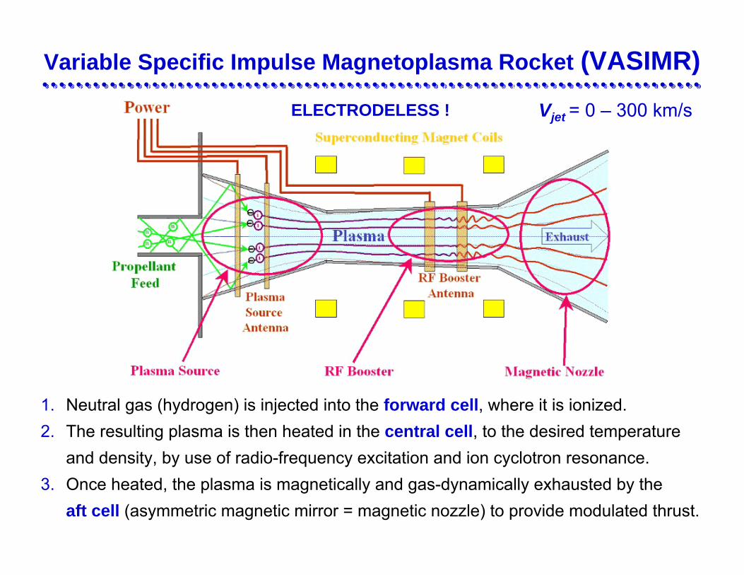
Variable Specific Impulse Magnetoplasma Rocket (VASIMR)
Vjet = 0 – 300 km/s
1. Neutral gas (hydrogen) is injected into the forward cell, where it is ionized. 2. The resulting plasma is then heated in the central cell, to the desired temperature
and density, by use of radio-frequency excitation and ion cyclotron resonance.3. Once heated, the plasma is magnetically and gas-dynamically exhausted by the
aft cell (asymmetric magnetic mirror = magnetic nozzle) to provide modulated thrust.
ELECTRODELESS !

Hall ThrustersPPPL
Buzek ClusterP5 Cluster
Michigan PDEPL:
12.3 cm HT
PPPL
12.3 cm HT
Power = 0.2 – 3 kW
Voltage = 0.1 – 1 kV
Current = 2 – 5 A
µ (Xe) = 2 – 5 mg/s
Vjet = 15 – 25 km/s
Thrust = 40 – 80 mN
Efficiency ~ 50%

Hall Thruster is an ExB Discharge Device
IH
CATHODE (neutralizer)
Magnetic coils
ANODE(gas distributor)
Magnetic core
Plasma jet
Ceramic walls
rLi >> Lchannel >> rLe

Hall Thruster Experiment at PPPL
2 kW Hall Thruster
Planar ProbeFor Plume
Measurements
Two-Plate EnergyAnalyzer
Probe ApparatusFor Near-AnodeMeasurements
Fast-ReciprocatingProbe Apparatus
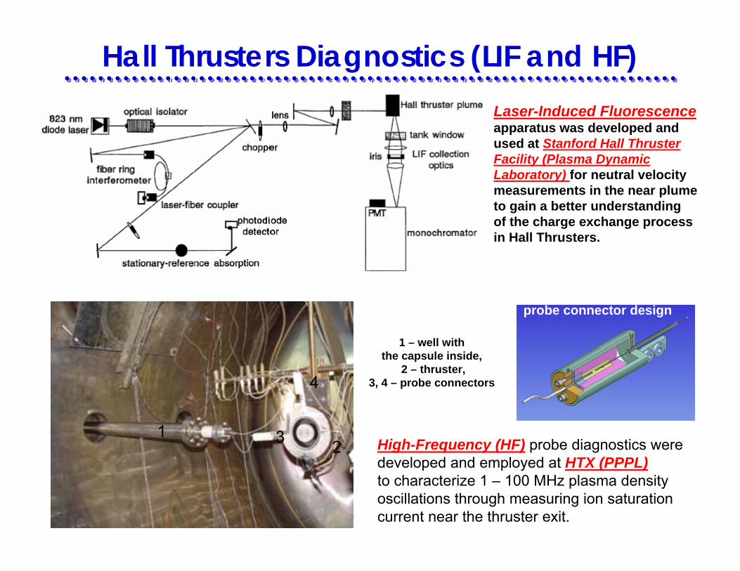
Hall Thrusters Diagnostics (LIF and HF)Laser-Induced Fluorescenceapparatus was developed and used at Stanford Hall Thruster Facility (Plasma Dynamic Laboratory) for neutral velocity measurements in the near plumeto gain a better understanding of the charge exchange process in Hall Thrusters.
123
4
1 – well with the capsule inside,
2 – thruster, 3, 4 – probe connectors
probe connector design
High-Frequency (HF) probe diagnostics weredeveloped and employed at HTX (PPPL)to characterize 1 – 100 MHz plasma densityoscillations through measuring ion saturationcurrent near the thruster exit.
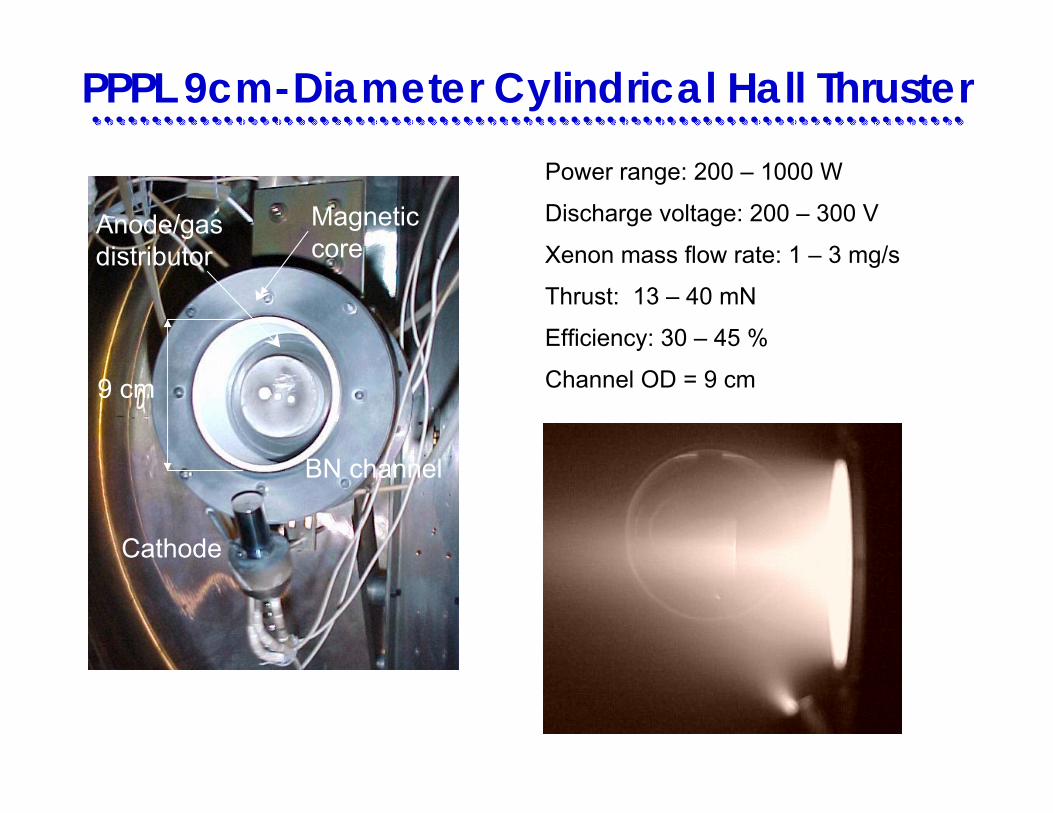
PPPL 9cm-Diameter Cylindrical Hall Thruster
Cathode
9 cm
BN channel
Anode/gasdistributor
Magnetic core
Power range: 200 – 1000 W
Discharge voltage: 200 – 300 V
Xenon mass flow rate: 1 – 3 mg/s
Thrust: 13 – 40 mN
Efficiency: 30 – 45 %
Channel OD = 9 cm

Cylindrical Hall Thruster has larger volume to surface ratio than conventional thrusters
N
N
E
B
AnodeCathode-neutralizer
Electromagnets
B
Ceramic channel
Ve
S
N
S
Annular part
• Electron drift is azimuthal ⇒closed drift
• Ion axial acceleration ∼ Ieθ x Br
• In a short annular part the density of neutrals is higher ⇒better for ionization
• Length of the annular region ∼ λion
• Compared to a conventional (annular)Hall thruster, the CHT has lowersurface-to-volume ratio ⇒potentially smaller wall losses in thechannel
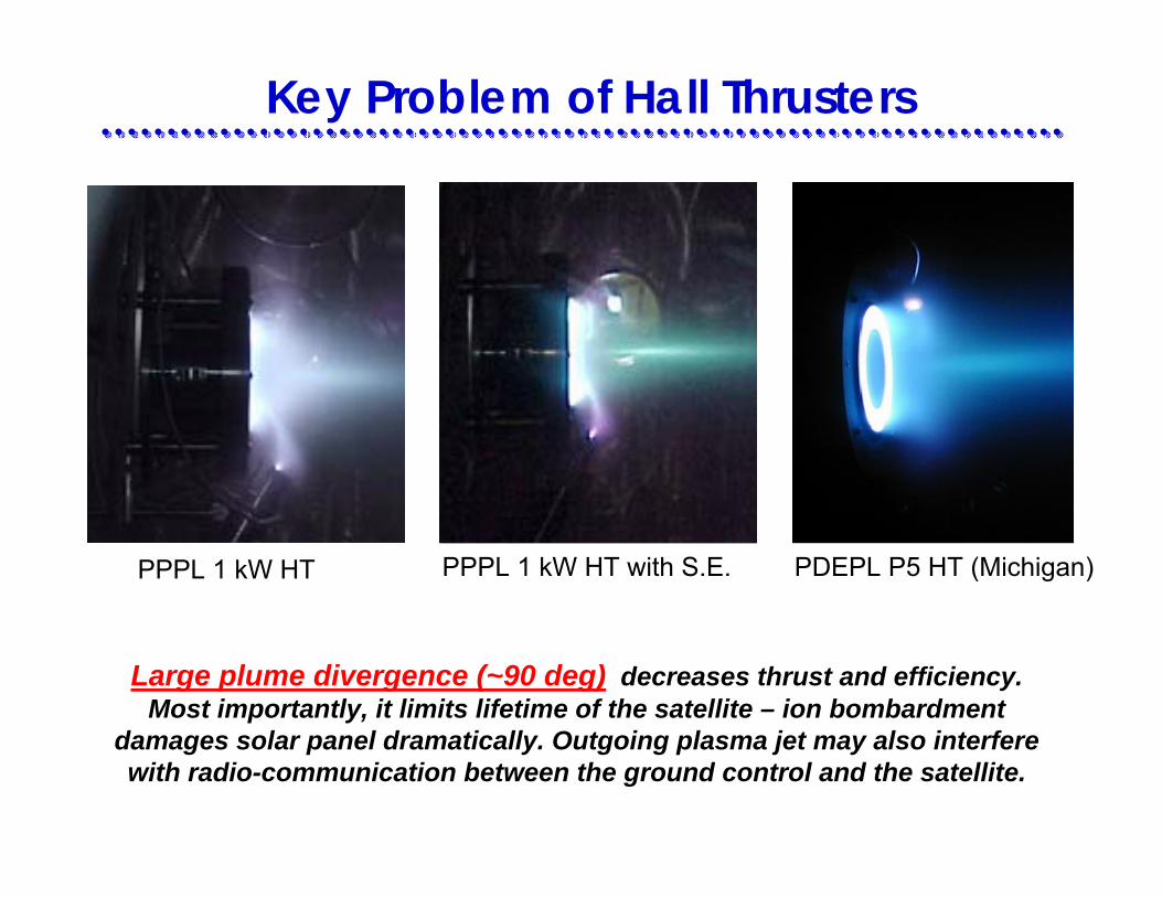
Key Problem of Hall Thrusters
PPPL 1 kW HT PPPL 1 kW HT with S.E. PDEPL P5 HT (Michigan)
Large plume divergence (~90 deg) decreases thrust and efficiency. Most importantly, it limits lifetime of the satellite – ion bombardment
damages solar panel dramatically. Outgoing plasma jet may also interfere with radio-communication between the ground control and the satellite.

Controlling Plume with Segmented Electrodes Anode Cathode
B E
Segmented electrodes(localize potential drop -reduce beam divergence
30
35
40
45
50
55
150 200 250 300 350
Discharge Voltage, V
Hal
f Plu
me
angl
e, d
eg
WS
NS1 floating
NS1 cathodebiasNS2 floating
NS2 cathodebiasNS3 floating
NS3 cathodebias
Single electrode configuration
Anode mass flow rate = 1.7 mg/sProbe
1 kW HT
Segmented Electrode
Grooves (anti-sputtering)

Temperature Profile in Hall Thrusters
Te = β φplβ = 0.08 – 0.14
1. In acceleration region:
Discharge Voltage, VMax
imum
Ele
ctro
n Te
mpe
ratu
re, e
V measured
µ = 5 mg/s
RESULTS:
2. Maximum electron temperaturesaturates with discharge voltage

Anode Sheath = Adjoint Space-Charge Layer
Positive Anode Fall = Electron-attracting Anode Sheath
z
V e
V i
Ano
de p
lane
Neg
ative
fallPo
sitive
fall
Cat
hode
pla
ne
( )zϕ
Cha
nnel
exi
t pla
ne
Sheath
Negative Anode Fall = Electron-repelling Anode Sheath

-7-5-3-113579
11
0 2 4 6 8 10 12 14
Distance from Anode, mm
Plas
ma
Pote
ntia
l, V
At channel median = 5 mg/s = 0, biased probe
CLEAN ANODE = NEGATIVE ANODE FALL
COATED ANODE = POSITIVE ANODE FALL
m anϕ
Decreasing Anode Area Reverses Anode Fall
400 V
300 V200 V
400 V
300 V
200 V

CLEAN ANODECOATED ANODE
Decreasing Anode Collecting Surface Area Manifests Itself
Positive anode fallNegative anode fall

Hall thruster operation appears to be MORE STABLE WITH COATED ANODE
(i. e. with Electron-Attracting Anode Sheath or Positive Anode Fall)
0
0.2
0.4
0.6
0.8
1
150 200 250 300 350 400 450
Rel
ativ
e O
scill
Am
pl
Discharge Voltage, V
Coated Clean
3 mg/s
3 mg/s
5 mg/s
5 mg/s
Discharge Current Oscillations Measurements
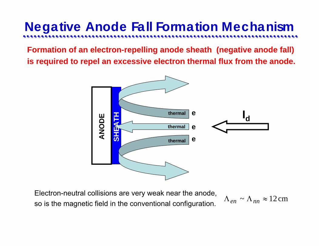
Formation of an electron-repelling anode sheath (negative anode fall)is required to repel an excessive electron thermal flux from the anode.
Negative Anode Fall Formation Mechanism
Electron-neutral collisions are very weak near the anode, so is the magnetic field in the conventional configuration.
cm12~ ≈ΛΛ nnen
AN
OD
E thermal
thermal
thermal
e
eeSH
EATH Id

Additional electron flux gets drawn into the anode by the electron-attracting sheath that appears at the inner, metal anode surfaces.
conductivesurface
stainlesssteel anode,
Φan = 0
Φplasma ~ – 6 V
ANODE
CAVITY
e–
e–
Id
only 40%of discharge
current
dielectriccoating
ΛD ~ 0.075 mm ∆B = 0.6 mm
Thermal electroncurrent constitutes
Positive Anode Fall Formation Mechanism
Axis of symmetry
Φ pl
, V Z, mm
-6
-4
-2
0
2
4
0 2 4 6 8 10 12
OW
IW
MC
B negΦ
pl,
V
Z, mm4
6
8
10
12
0 2 4 6 8 10 12
OW
IW
MC
B 0
Φ pl
, V
Z, mm
-202468
101214
0 2 4 6 8 10 12
OW
IW
MC
B pos
B0 Bpos
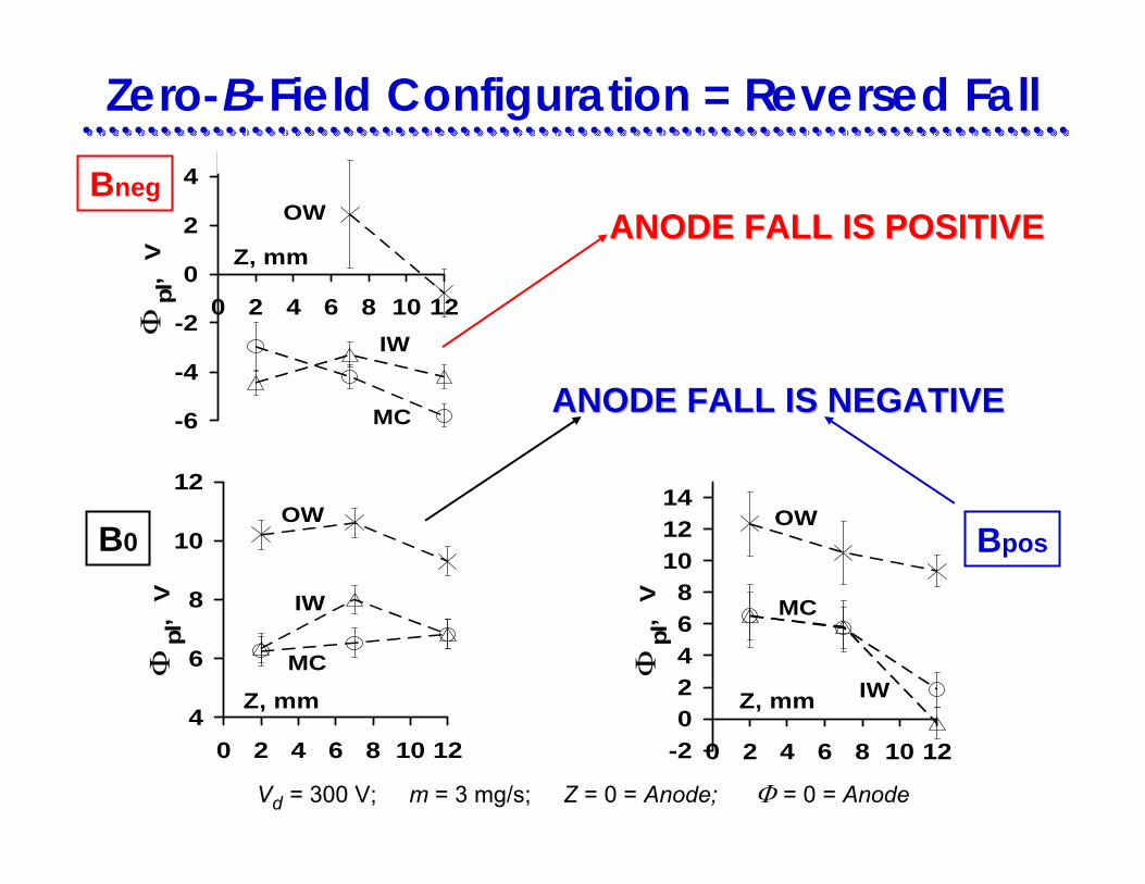
Zero-B-Field Configuration = Reversed Fall
ANODE FALL IS POSITIVEANODE FALL IS POSITIVE
Vd = 300 V; m = 3 mg/s; Z = 0 = Anode; Φ = 0 = Anode
Bneg
ANODE FALL IS NEGATIVEANODE FALL IS NEGATIVE

0
5
10
15
20
25
30
0 1 2 3 4 5 6 7 8 9Distance from Anode, cm
Elec
tron
Tem
pera
ture
, eV
B0
Bpos
Bneg
Quasi-1D Model
300VdV = 3mg/sm =
1. Input parameters:
2. System of fluid equations for 3-species (e, i, n) quasineutral plasma. Includes ion wall losses terms “quasi-1D”
03 profiles ( ), , , = = Experimental values
r dB z I n sheath
3. Fitting parameter, α, for electron cross-field mobility, µe: ( )16erB z
αµ =
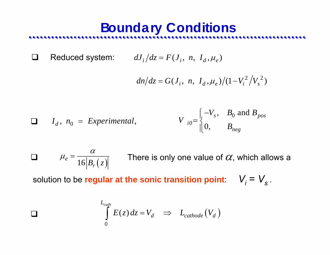
Boundary Conditions
There is only one value of α, which allows a
solution to be regular at the sonic transition point: Vi = Vs .
Reduced system: ( , , , )i i d edJ dz F J n I µ=
2 2( , , , ) (1 )i d e i sdn dz G J n I V Vµ= −
0, ,dI n Experimental=0
0
, and
0,s pos
ineg
V B BV
B
−⎧⎪= ⎨⎪⎩
( )16erB z
αµ =
( )0
( )cathL
d cathode dE z dz V L V= ⇒∫