By Kyle Lick. About EDI ◦ Who is Engine Distributors ◦ Industrializing a Ford Engine Engine...
120
Ford Industrial Service Engine Training By Kyle Lick
-
Upload
travis-caudle -
Category
Documents
-
view
233 -
download
2
Transcript of By Kyle Lick. About EDI ◦ Who is Engine Distributors ◦ Industrializing a Ford Engine Engine...

Ford Industrial Service Engine
Training By
Kyle Lick

About EDI Who is Engine Distributors Industrializing a Ford Engine
Engine Basics Identification Specifications
Cooling System Water Pump Thermostat
Fuel system; Gasoline, LPG, NG Differences in Setups Gasoline Fuel Pump, Fuel Block, Injector Wiring Gaseous Fuel DEPR and Lock Off Valve Wiring
Exhaust System General Layout O2 Sensor Positioning and Wiring
Engine Electronics GCP Specs/Capabilities Controls Interface Sensors Fuse box Component Wiring; MAP, Throttle, CAM, CRANK, ECT/CHT Starting and Charging Circuits
Engine Display Interface Software (EDIS) Purpose Installing the Software Using the Software Using the MIL
Overview

Engine Distributors, Inc. has been a leading distributor of Ford, Deutz, Kubota, and Crusader engines and parts for over 30 years. As a family owned business since 1958, EDI is recognized as a leader in the industry. President Glenn Cummins Jr., with sons Glenn Cummins III and Jaime Cummins have taken all of the necessary steps to provide OEM’s and consumers with product support, sales and service. Our highly experienced personnel, coupled with our deep product line of inventory, insure our commitment to total customer satisfaction. Our corporate office is located in Blackwood, NJ and with our 5 branch locations along the East Coast and Worldwide distributor network; EDI is dedicated to distributing our product lines domestically and globally.
Who is Engine Distributors?

EDI purchases base engines from Ford Ford has excess capacity within their plants Engines selected are based on availability and
whether it was designed for dry fuels
EDI fits the control and fuel system to the engine Engine is EPA and CARB certified
Other items are added onto the engine Bell housing and flywheel Cooling packages
Industrializing a Ford Engine
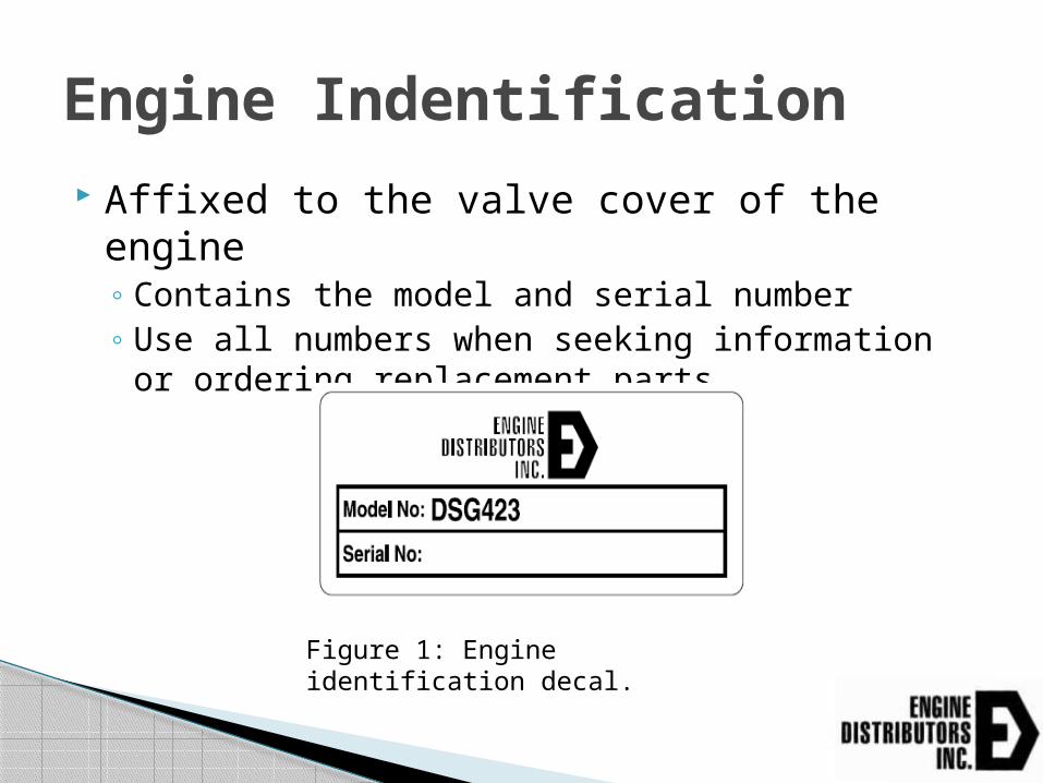
Affixed to the valve cover of the engine Contains the model and serial number Use all numbers when seeking information or
ordering replacement parts
Engine Indentification
Figure 1: Engine identification decal.

Also located on the engine manifold
Emissions Label
Figure 2: Emissions label
*Useful life is the amount of time the engine and its emissions components should be able to comply with emissions

Engine SpecificationsTSG416 Engine Type…………….. I-4, SOHC Bore and Stroke………… 3.23” x 2.97” Displacement…………… 1.6L (97.4 CID) Compression Ratio…….. 9.5:1 Oil Capacity……………… 4.4 qts. Including filter Net Weight………………. 200 Lbs. Basic Dimensions.……... L24.1” x W18.9”x H24.7”
Certified on Gasoline, LPG, and NG 650 – 3200rpm
SAE 5 Housing and SAE 7.5” flywheel available

Engine SpecificationsMSG425 Engine Type…………….. I-4, DOHC Bore and Stroke………… 3.5”x3.93” Displacement…………… 2.5L (152.5 CID) Compression Ratio…….. 9.7:1 Oil Capacity……………… 7 qts. Including filter Net Weight………………. 351 Lbs. w/acc. Basic Dimensions.……... L30.3” x W23.3”x H32.6”
Certified on Gasoline, LPG, and NG 650 – 3200rpm
SAE 4 Housing and SAE 10” flywheel available

Engine SpecificationsWSG1068 Engine Type…………….. V-10, SOHC Bore and Stroke………… 3.55” x 4.17” Displacement…………… 6.8L (415 CID) Compression Ratio…….. 9:1 Oil Capacity……………… 6 qts. Including filter Net Weight………………. 640 Lbs. Basic Dimensions.……... L30.4” x W28.5”x H31.7”
Certified on Gasoline, LPG and NG 650 – 3200rpm
SAE 3 Housing and SAE 11.5” flywheel available

Fuel Type Gasoline (corrected per SAE J1995)
Fuel Spec……………..87 A.K.I.
TSG416 Inter. Gross Power….56 HP @3200 RPM Cont. Gross Power….47 HP @ 3200 RPM Inter. Gross Torque…92 Ft. Lbs. @ 3200 RPM Cont. Gross Torque…79 Ft. Lbs. @ 3200 RPM
MSG425 Inter. Gross Power….84 HP @3200 RPM Cont. Gross Power….75 HP @ 3200 RPM Inter. Gross Torque…137 Ft. Lbs. @ 3200 RPM Cont. Gross Torque…123 Ft. Lbs. @ 3200 RPM
Power Specifcations
WSG1068 Inter. Gross Power….222 HP @3200 RPM Cont. Gross Power….201 HP @ 3200 RPM Inter. Gross Torque…360 Ft. Lbs. @ 3200 RPM Cont. Gross Torque…324 Ft. Lbs. @ 3200 RPM

Liquid cooled Engine mounted coolant pump External radiator
Full flow system regulated behind thermostat Located behind water outlet connection Controls and maintains engine temperature
Typically opens at 180ºF, fully open around 200ºF
Cooling System
Figure 4: 2.3L Belt layout

Driven off of the main FEAD belt
Full flow depending on engine speed
Regulated by thermostat
Water Pump

Typically starts to open between 180-190° F
Fully Open between 200-210°F
Engines will operate between 190-210°F depending on load and ambient temperatures.
Located at coolant inlet on 2.3/2.5L (front intake side of engine)
Located back of 1.6L at the coolant inlet
Sensors will be covered in the electronics section
Thermostat

EDI offers a suction and pusher fan for every engine model
TSG416 and MSG425 use separate belt drive for the fan. Tension is applied by tightening the bearing bracket up.
DSG423 and WSG1068 run the fan off of the main FEAD. Tension is supplied by an auto tensioner DSG423 runs off a lone fan pulley WSG1068 runs off of the coolant pump
Cooling Fans

MSG425 Fan Drive
TSG416 Uses Similar Type of Drive
Fan Pulley
Extended Crank Pulley
Main FEAD Belt
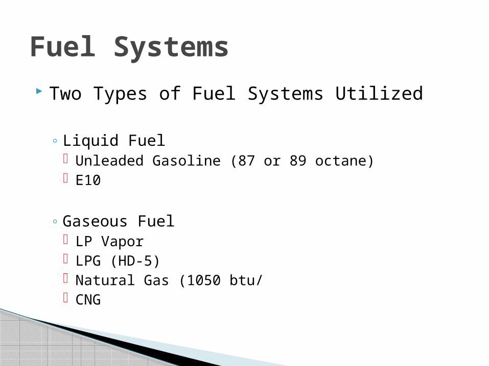
Two Types of Fuel Systems Utilized
Liquid Fuel Unleaded Gasoline (87 or 89 octane) E10
Gaseous Fuel LP Vapor LPG (HD-5) Natural Gas (1050 btu/ CNG
Fuel Systems
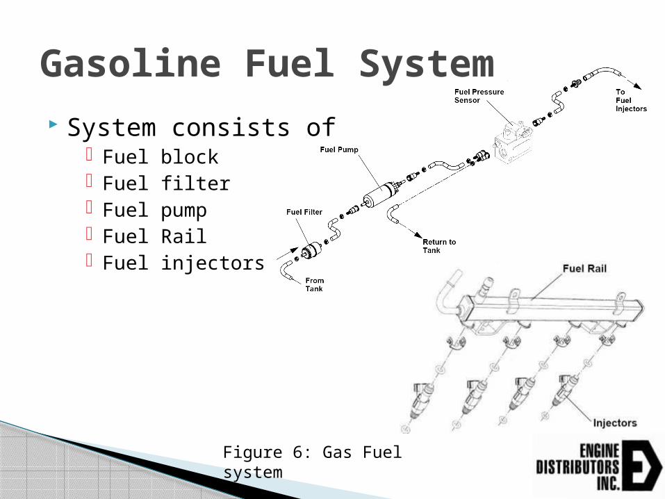
System consists of Fuel block Fuel filter Fuel pump Fuel Rail Fuel injectors
Gasoline Fuel System
Figure 6: Gas Fuel system

Fuel block provides fuel temperature and pressure readings to ECU
Fuel pump is PWM controlled based on the pressure reading from fuel block Fuel pressure is a preset value in the ECU
TSG416: 54.6 psia DSG423: 74.7 psia MSG425: 58.0 psia WSG1068: 58.0 psia
Gasoline Fuel System

Fuel Pump Typical Voltages Fuel Pump positive to direct ground
~12 volts DC Power is supplied through 15Amp fuse and fuel pump relay
Fuel Pump positive to fuel pump negative ~6-7 volts DC depending on pressure
Fuel Block Wiring / Voltages (four wires) Pressure – White/Lt Green – Typically 1.0 to 2.7 volts Temperature – Lt. Green/White – 0 to 5 volts 5 Volt Reference – Brown/White – 5 volts 5 Volt Return – Gray/Red
Gasoline Fuel System

Each injector has a red wire Supplies 12 volts from relayed power Always on when cranking and running
Color wires are ground pulses from ECU This triggers the fuel injectors to spray
Timing is preset in the ECU
Fuel Injectors

Fuel Injector Wiring
LPG System
Natural Gas System
CNG System
LP Vapor System
Gaseous Fuel Systems

Liquefied Petroleum Gas (LPG Grade HD-5) Propane is vaporized and pressure reduced
Pressure is regulated with an Electronic Pressure Regulator (EPR)
Fuel goes to the mixer where it is mixed with air and then goes through the throttle and into the intake air manifold
LPG Fuel System
Consists of Dry Fuel Mixer Electronic Pressure Regulator Vapor Regulator Lock off Valve
This is true for all current EDI Ford engines TSG416 and MSG425 utilize the same
components for their LPG fuel system WSG1068s components are the same as the
smaller displacement engines except larger in scale
LPG Fuel System
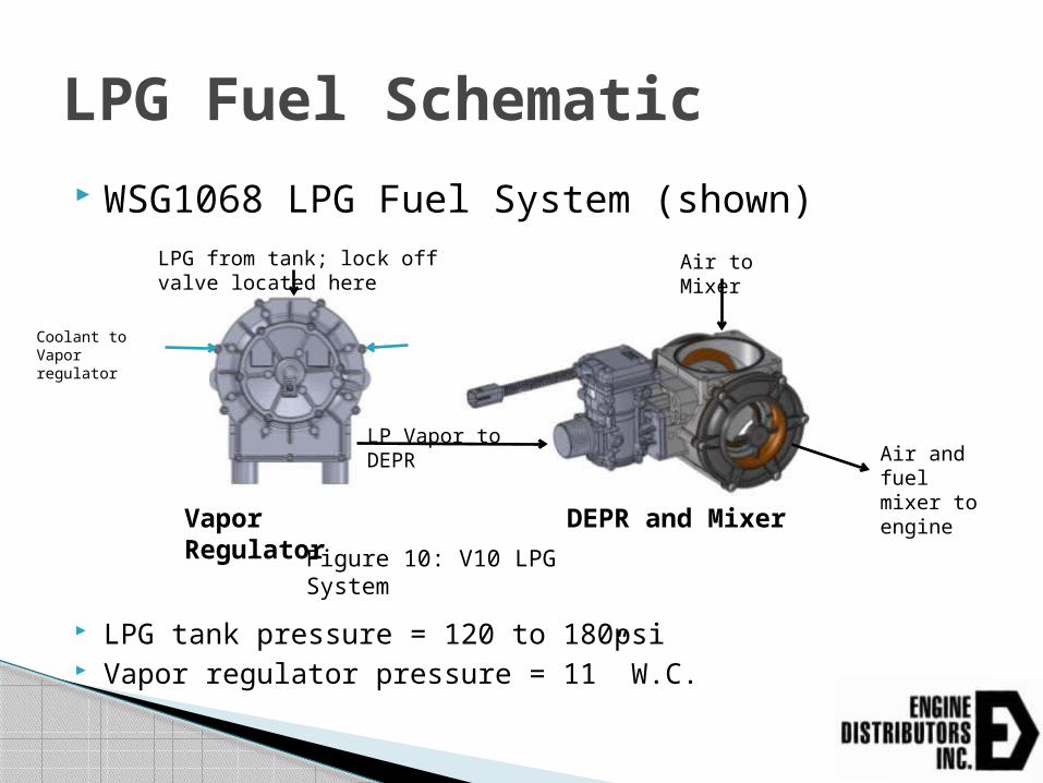
WSG1068 LPG Fuel System (shown)
LPG tank pressure = 120 to 180psi Vapor regulator pressure = 11” W.C.
LPG Fuel Schematic
Figure 10: V10 LPG System
Vapor Regulator
DEPR and Mixer
LPG from tank; lock off valve located here
Air and fuel mixer to engine
LP Vapor to DEPR
Air to Mixer
Coolant to Vapor regulator

LPG System Pict
TSG416
Mixer
DEPR
Lock Off
Vapor Regulator

1050 btu/ft^3 is supplied to the engine at 11 inches of water columun
Pressure is then regulated with an Electronic Pressure Regulator (EPR)
Fuel goes to the mixer where it is mixed with air and then goes through the throttle and into the intake air manifold
Natural Gas Fuel System

WSG1068 NG Fuel System (shown)
Natural Gas pressure to DEPR = 11” W.C. Same for whole product line regardless of engine size
Natural Gas Fuel Schematic
DEPR and Mixer
LPG from tank; lock off valve located here
Air and fuel mixer to engine
NG to DEPR
Air to Mixer

Natural Gas System Pict
MSG425 Engine
Mixer
DEPR
Lock off

Fuels stored at higher pressures
LP Vapor – Propane already in a vapor state; typically at 300psi Setup is similar to natural gas; low pressure lock off valve Pressure needs to be reduced to 11” W.C. before reaching
the electronic pressure regulator
CNG – Natural stored at ~3000psi. Similar to LPG setup; high pressure lock off valve Pressure needs to be reduced to ~100-300psi before
entering supplied regulator on engine
CNG and LP Vapor

DEPR (Direct electronic pressure regulator)
TSG416
WSG1068

Actuator in the EPR controls the fuel pressure to the mixer Actual “delta P” matches the GCP command
Extremely accurate open loop type of fuel control
After preset amount of time (50 seconds), engine goes to closed loop control Uses information from the pre and post cat oxygen
sensors to allow further adjustment to meet emission regulations
DEPR (Direct Electronic Pressure Regulator)
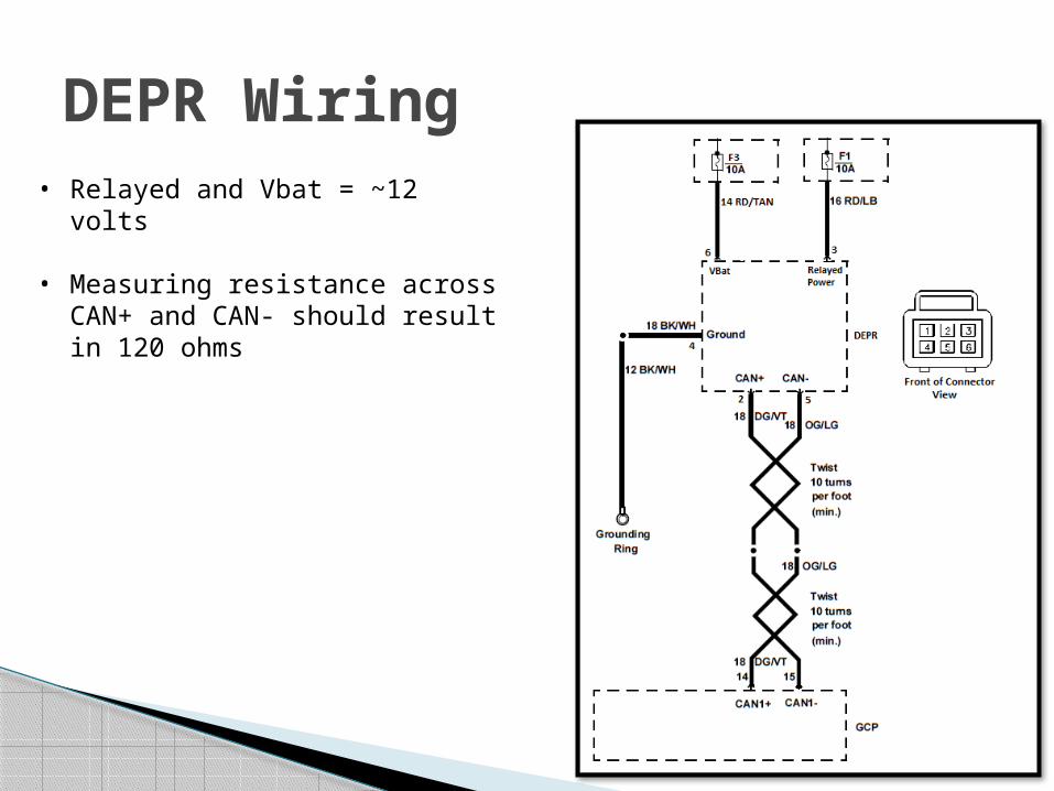
DEPR Wiring• Relayed and Vbat = ~12 volts
• Measuring resistance across CAN+ and CAN- should result in 120 ohms

Mixer
WSG1068
TSG416

Device by which fuel can be added to passing air flow
Amount of fuel is related to amount of air passing through the mixer
This is controlled by the differential pressure across the diaphragm
More air the engine demands the lower the pressure in the throat is which relates to the diaphragm
Diaphragm overcomes the spring force holding it down to allow more fuel to mix with the air
Dry Fuel Mixer

Figure 12: Diaphragm Mixer Operation
12 volt DC Solenoid driven valve located before the EPR or vapor regulator
Only open when the engine is starting and running When user initiates engine shutdown, the valve
closes Prevents fuel from getting to the intake system Engine will continue to run for about 3 seconds to use up
the remaining fuel in the manifold Prevents an engine backfire from occurring during the
next startup Referred to as Fuel Run-Out Low pressure valve used for NG/LP Vapor Higher pressure valve used for LPG/CNG
Lock Off Valve

Lock Off Valve Positioning Lock off should be placed as close as
possible to vapor regulator (LPG) or DEPR (NG)
This will reduce fuel run-out time
LPG Vapor Regulator
DEPR and Mixer
Lock Off Here on LPG
Lock Off Here on NG
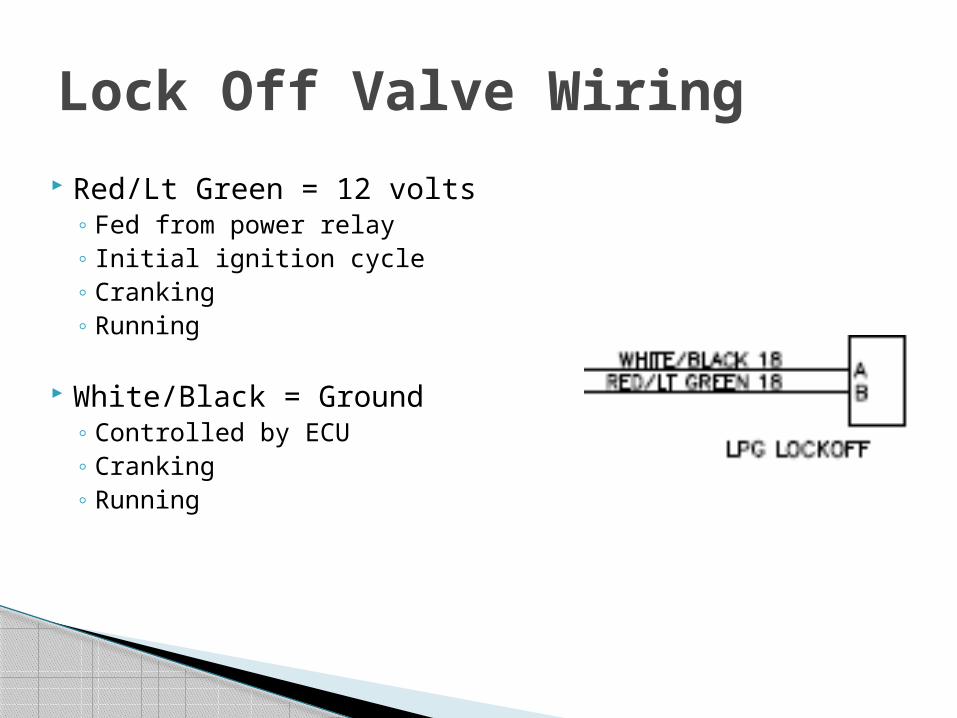
Red/Lt Green = 12 volts Fed from power relay Initial ignition cycle Cranking Running
White/Black = Ground Controlled by ECU Cranking Running
Lock Off Valve Wiring

Vapor Regulator (Vaporizer) Used on LPG only Fuel from tank connects directly Combined with the EPR on the 2.3L Separate on all other engines
(D)EPR (Electronic Pressure Regulator) Precisely controls the fuel into the engine Used for both LPG and NG 11” W.C. to EPR on NG
Lock Off valve Prevent fuel from building up in the intake which could cause a
backfire Mixer
Where the fuel from the EPR is mixed with air Governor
After the fuel and air is mixed the governor regulates the mixer into the air intake manifold
Dry Fuel System Review

Position of the vapor regulator to mixer/DEPR is very important Refer to emission install instructions for:
Length of LPG hose between vapor regulator and mixer
Height relative to mixer If these are not followed this could lead to
premature failure of the vapor regulator Could cause oils to build up in vapor regulator and
LPG lines Keep Distance of Lock off valve to vapor regulator
or DEPR as short as possible
Dry Fuel System Installation Notes

Exhaust must be a closed system Emission install instructions list
Distance of pre-cat sensor from exhaust manifold Distance of center of catalyst from exhaust manifold Length of solid pipe required after post-cat sensor to
avoid false oxygen readings
Ensure oxygen sensors are properly oriented to prevent water from burning out the sensors
Use 409 stainless steel pipe or equivalent Must last useful life of engine
Exhaust System

Exhaust Layout Example
Pre-cat sensorMust be within 8 inches of exhaust manifold
Post-cat sensor
Figure 13: Exhaust layout

Oxygen Sensor Positioning
Must be inclined at least be 10º above the horizontal
Figure 14: O2 Sensor Positioning

Gray/Red – 5 volt return
Gray/Lt. Blue – Sensor signal to ECU 0 – 1.2 volts Post cat sensor = Gray/Yellow
Red – 12 volts from relayed power
Black/Lt Green – Heater ground
Oxygen Sensor Wiring

GCP (Global Control Platform) 90 pin computer that connects to the below
components on the engine
GCP Capabilities
Figure 15: GCP components

12 volt system only (6-18volts) IP 67 rated -40°F to 225°F normal operating
temp. 1m drop onto concrete surface 15 mins. in four inches of water 8G vibration at ECM header pins 0.005 AMP draw when powered
down
GCP Specs

Programmable four speed electronic governing, throttle-by-wire or variable speed control governing.
Programmable emergency warning/shut-down feature for high water temperature, low oil pressure, etc.
Starter lockout Programmable over speed protection Automatic altitude compensation Sequential port fuel injection (gasoline) with pressure
regulator to precisely control fuel delivery Certified closed loop dry fuel control Configurable outputs available based on ECT, RPM or MAP
signals and customer requirements Diagnostic software allows viewing of historical and active
faults with on-demand diagnostics to assist technicians and reduce equipment downtime.
GCP Features
Protects the user and the engine from hazards such as: Over speed Over temperature Over voltage Low oil pressure Unauthorized tampering Over cranking the starter motor Dry fuel run-out
GCP Safety Features

Operating conditions being read Engine coolant temperature Exhaust oxygen content Manifold absolute pressure Battery voltage Throttle Position/Electronic actuator Fuel pump voltage Intake air temperature Camshaft position Crankshaft position
GCP Inputs

Throttle 0 – 5 volts with an IVS
Potentiometer 0 – 5 volt input
Discrete Speed 12 volt signals directly ramp the engine to a set speed
Tap Up / Tap Down 12 volt signals variably increases or decreases the speed
J1939 Can use TSC1 Commands
GCP Control

Systems controlled Spark Electronic throttle control Electric fuel pump or Dry Fuel Pressure Regulator Diagnostics – Malfunction indicator lamp (check
engine lamp) Diagnostics – Data Link Connector (DLC)
GCP Outputs
Outputs common J1939 Parameters Throttle position Engine Speed Engine Temperature Oil Pressure (9psi or 99psi with switch) Engine Hours Fuel Consumption Battery Voltage Faults codes via a SPN and FMI #
Can also take throttle commands via TSC1 Address is configurable
GCP J1939
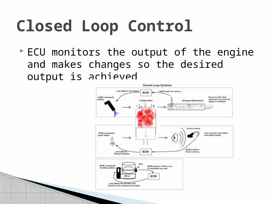
ECU monitors the output of the engine and makes changes so the desired output is achieved
Closed Loop Control

Certain conditions must be must Coolant temp of 100 deg[F] Run time of engine, 15 seconds after reaching
temp above
Once closed loop ECU actively monitors the EGO sensor to
determine fueling accuracy If it is not accurate it will begin adding or
subtracting fuel to achieve a stoichiometric fuel mixture
Closed Loop Fueling

Primary interface from the OEM customer wiring to the engine harness 5080030 – Pin kit with 42 pin connector F8JL14324AC – 42 pin connector with wire leads
42 Pin Connector
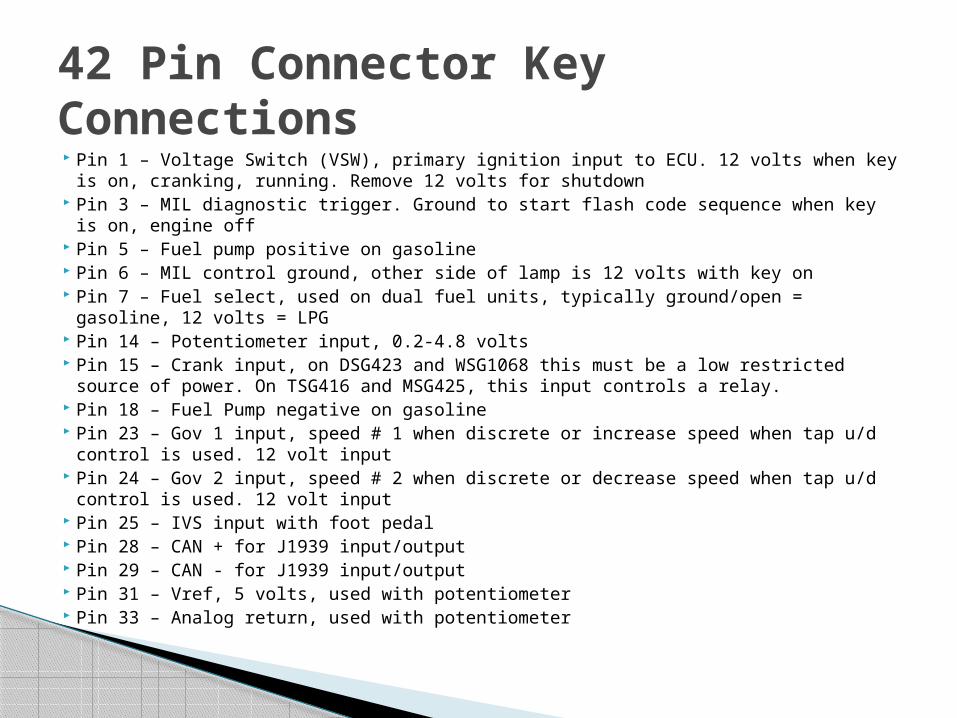
Pin 1 – Voltage Switch (VSW), primary ignition input to ECU. 12 volts when key is on, cranking, running. Remove 12 volts for shutdown
Pin 3 – MIL diagnostic trigger. Ground to start flash code sequence when key is on, engine off
Pin 5 – Fuel pump positive on gasoline Pin 6 – MIL control ground, other side of lamp is 12 volts with key on Pin 7 – Fuel select, used on dual fuel units, typically ground/open = gasoline, 12 volts
= LPG Pin 14 – Potentiometer input, 0.2-4.8 volts Pin 15 – Crank input, on DSG423 and WSG1068 this must be a low restricted source of
power. On TSG416 and MSG425, this input controls a relay. Pin 18 – Fuel Pump negative on gasoline Pin 23 – Gov 1 input, speed # 1 when discrete or increase speed when tap u/d control
is used. 12 volt input Pin 24 – Gov 2 input, speed # 2 when discrete or decrease speed when tap u/d control
is used. 12 volt input Pin 25 – IVS input with foot pedal Pin 28 – CAN + for J1939 input/output Pin 29 – CAN - for J1939 input/output Pin 31 – Vref, 5 volts, used with potentiometer Pin 33 – Analog return, used with potentiometer
42 Pin Connector Key Connections

Electronic Distributor less Ignition System (EDIS) Individual ignition coils (DSG423/MSG425/WSG1068)
Located directly above each spark plug Ignite the fuel in the cylinders Each coil has a red wire; 12 volts from relayed power Engine ECU provides ground to fire coil (color wires)
Spark is only allowed when the CAM and crank sensor are detected together
Distributorless Ignition System
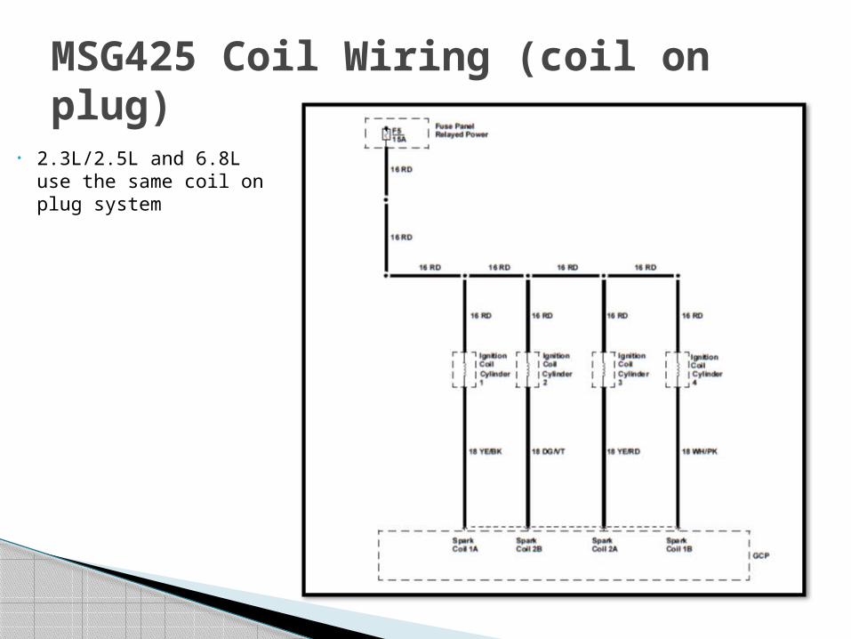
MSG425 Coil Wiring (coil on plug)
• 2.3L/2.5L and 6.8L use the same coil on plug system

Waste Spark Circuit 1 fires
cylinders 1 & 4
Circuit 2 fires cylinders 2 & 3
TSG416 Coil Pack Wiring
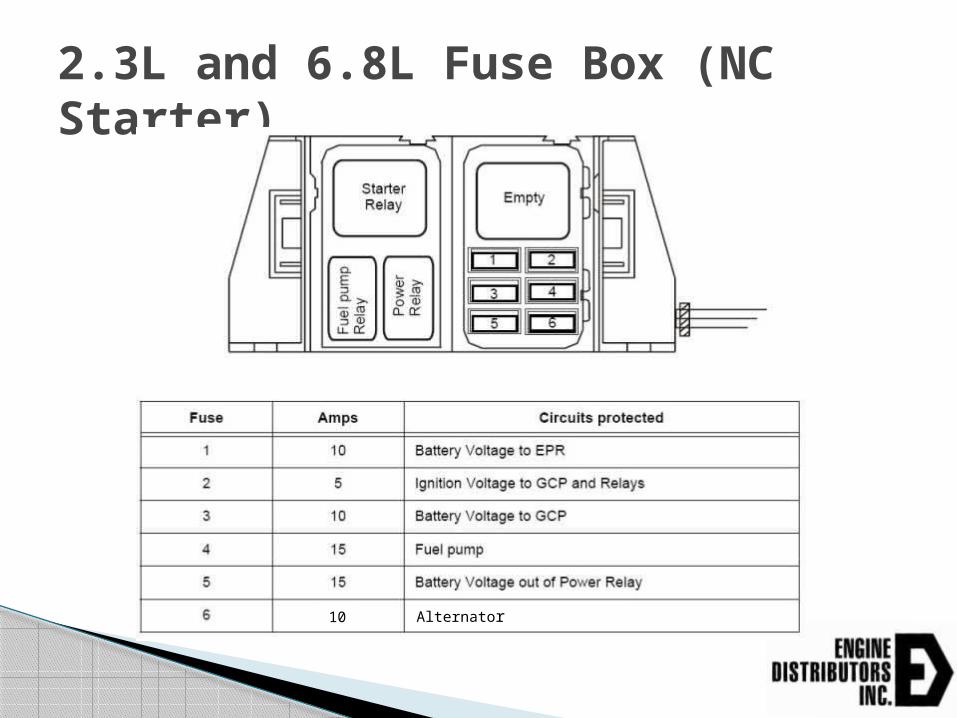
2.3L and 6.8L Fuse Box (NC Starter)
Alternator10

1.6L and 2.5L Fuse Box (NO Starter)
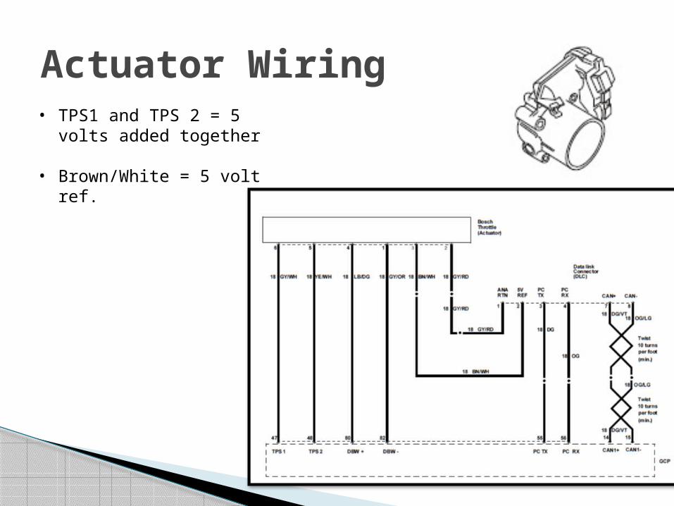
Actuator Wiring• TPS1 and TPS 2 = 5
volts added together
• Brown/White = 5 volt ref.
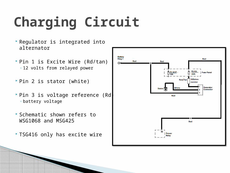
Regulator is integrated into alternator
Pin 1 is Excite Wire (Rd/tan) 12 volts from relayed power
Pin 2 is stator (white)
Pin 3 is voltage reference (Rd) battery voltage
Schematic shown refers to WSG1068 and MSG425
TSG416 only has excite wire
Charging Circuit

DSG423 and WSG1068
Starter relay is a pass through
ECU opens circuit after 8 seconds of continuous cranking to prevent over cranking
Voltage to the solenoid is provided by the users panel side
Starting Circuit – NC Starter

TSG416 and MSG425 Starting circuit
Starter Solenoid Engagement circuit is internal to the wiring harness
ECU controls ground side of starter Relay.
User controls positive side of starter relay.
Starting Circuit – NO Starter

1.6L and 2.5L utilize a ECT sensor Engine coolant temperature direct measurement Both located on back of engine near the coolant outlet
2.3L and 6.8L utilize a CHT sensor Cylinder head temperature measurement Coolant temp. displayed is based off of calculation from
CHT measurement 6.8L located underneath the intake manifold towards the
front of the engine 2.3L located in between coils 2 and 3 on top of the engine
Both sensor types are 0 – 5 volts
ECT/CHT Sensor

Pull up type circuit When open the circuit defaults to 5 volts Sensor applies a resistive load between the
sensor signal and its ground and brings down the voltage
Gray/Red – 5 volt return
Lt Green/Red (37) – Signal to ECU
ECT/CHT Wiring

Resistance vs. TemperatureMSG425
DSG423

Resistance vs. TemperatureWSG106
8TSG416

Intake air temperature and manifold air pressure measurement sensor
Intake air = ~ambient air temperatures
MAP = 4psia to 14.7psia The greater the delta from 14.7, the smaller the load The closer to 14.7psia, the larger the load
Both are 0 – 5 volt sensors.
Same sensor used on all Ford NA engines
TMAP Sensor
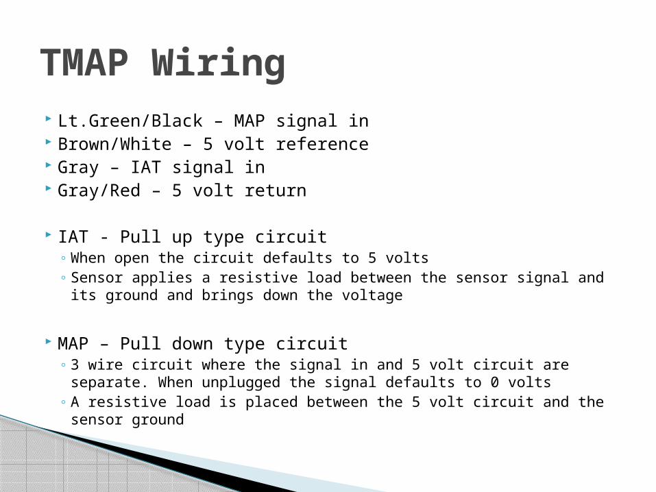
Lt.Green/Black – MAP signal in Brown/White – 5 volt reference Gray – IAT signal in Gray/Red – 5 volt return
IAT - Pull up type circuit When open the circuit defaults to 5 volts Sensor applies a resistive load between the sensor signal and its
ground and brings down the voltage
MAP – Pull down type circuit 3 wire circuit where the signal in and 5 volt circuit are separate.
When unplugged the signal defaults to 0 volts A resistive load is placed between the 5 volt circuit and the sensor
ground
TMAP Wiring

2.5L/1.6L – Hall effect with pull-up Three wire sensors
5 volt reference CAM+: Signal CAM –: 5 volt return
2.3L/6.8L Magnetic Pickup Two wire sensor; crank+
and crank- Typical resistance values
2.3L: 0.422 kΩ 6.8L: 0.388 kΩ
CAM SensorComponent Measurement Unit
CAM Sensor:Viewing PINS with sensor side
down
5.2 MΩOL4.6 MΩ
MSG425 CAM sensor resistance Measurements
Component Measurement Unit
CAM Sensor:Viewing PINS with sensor side
down
265 kΩOL2.6 MΩ
TSG416 CAM sensor resistance Measurements

1.6L/2.3L/2.5L/6.8L – Magnetic pickup Two wire sensor of crank+ and crank-
Typical resistance values 1.6L: 0.388 kΩ 2.3L: 0.459 kΩ 2.5L: 0.452 kΩ 6.8L: 1.3 Ω
2.3L/2.5L/6.8L – Read off of the front crank pulley
1.6L – Reads off of the flywheel
Crank Sensor

Monitors engine noise to prevent pre-ignition Two wire sensor – knk+ and knk-
Typical resistance values 1.6L: 1Ω 2.3L: 4.8 MΩ 2.5L: 4.8 MΩ
Knock Sensor

All engines utilize a normally open switch Open without pressure Closed with pressure Monitored by ECU and will cause a shutdown if
open for 15 seconds when above 650 RPM
Typically opens/closes at 7psig
0 volts on circuit when running 5 volts on circuit when low or off
Oil Pressure Switch

Only on the MSG425
Constant 12volts on hot side; at initial key on, cranking, and running
Ground is PWM Controlled
Will through DTC 11: Intake cam/distributor position error Typically a result of the
positive or PWM wire being disconnected
MSG425 Variable Valve Timing Solenoid

Three methods to obtain fault codes
1. Flash codes out via MIL (malfunction indicator lamp)
2. Retrieve the fault using the GCP display software
3. Via SPN and FMI #s from CAN display
Obtaining Fault Codes
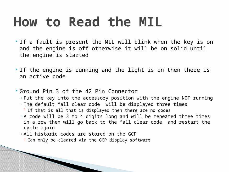
If a fault is present the MIL will blink when the key is on and the engine is off otherwise it will be on solid until the engine is started
If the engine is running and the light is on then there is an active code
Ground Pin 3 of the 42 Pin Connector Put the key into the accessory position with the engine NOT running The default “all clear code” will be displayed three times
If that is all that is displayed then there are no codes A code will be 3 to 4 digits long and will be repeated three times in a
row then will go back to the “all clear code” and restart the cycle again All historic codes are stored on the GCP
Can only be cleared via the GCP display software
How to Read the MIL

TSG416/DSG423/WSG1068 1 – 2 – 3
MSG425/All future engines 1 - 6 – 5 - 4
All Clear Code
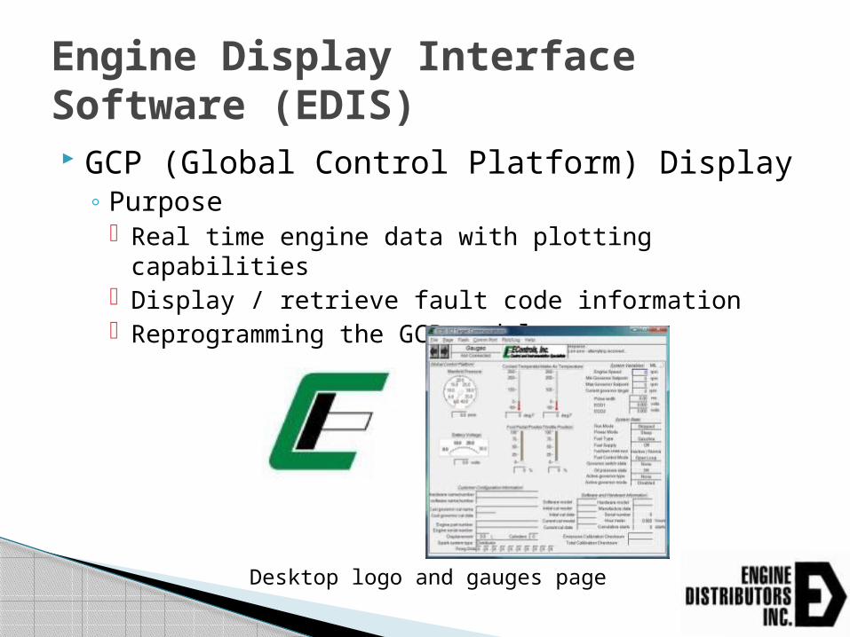
GCP (Global Control Platform) Display Purpose
Real time engine data with plotting capabilities Display / retrieve fault code information Reprogramming the GCP module
Engine Display Interface Software (EDIS)
Desktop logo and gauges page

Serial connection to the PC Can use a USB to serial adapter if needed
Connector below attaches to adapter located on the engine harness
Cable
Figure 18: GCP connector

Open the CD “GCP Display” Latest_GCP_Display
PC_Display Double Click “GCP Display” file
Follow install instructions Once installed copy password from gcp password
text file Paste password into prompt box when opening the
software
Installing the Software
Figure 19: Enter GCP password

Menus located on top of the screen File Menu: Used primarily to perform disk and file management
functions.
Page Menu: Used to select the active page and configure which pages will be visible for use during a software session.
Flash Menu: Commits updated calibration variables to flash memory
Comm Port Menu: Selects the PC’s active serial communication port and displays communication statistics.
Plot/Log Menu: Graphically plots or numerically logs static and dynamic variables and metrics that have been tagged for plotting or logging. Tag by right clicking a variable.
Help: Provides general information about EDIS and defines shortcuts for use in the software
In the software
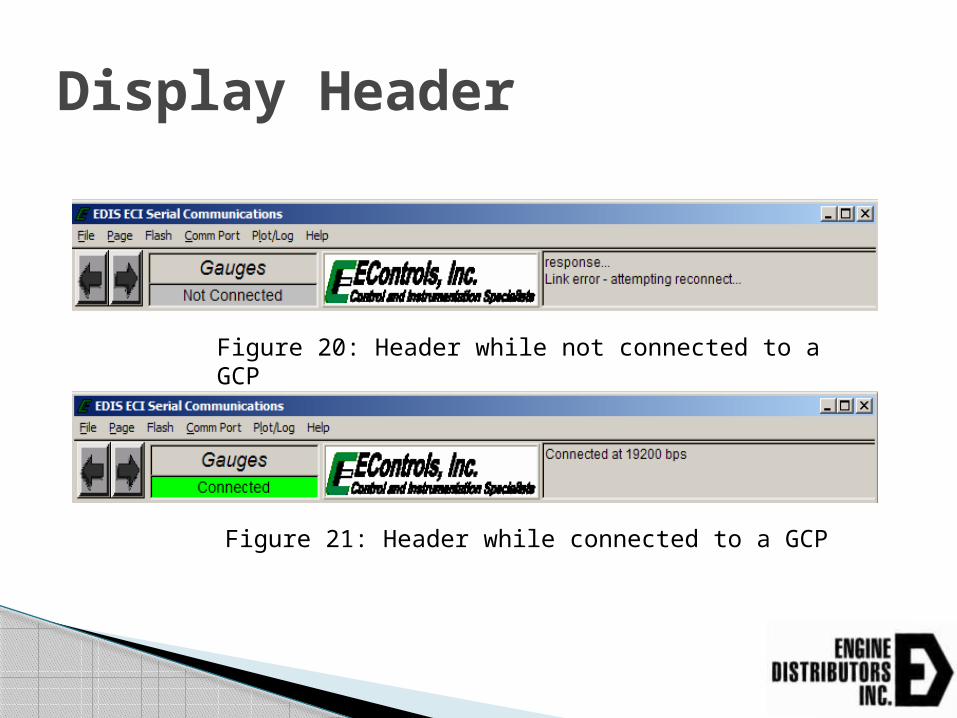
Display Header
Figure 20: Header while not connected to a GCP
Figure 21: Header while connected to a GCP

Save Calibration to Disk: Saves calibration variables, accessible from the display software, from the GCP’s flash memory to the PC.
Load Calibration from Disk: Loads a partial calibration from a
calibration file on the PC to the GCP’s flash memory. Only variables for which your password has write access will be updated.
Clear Cal Tags: Removes all calibration tags from EDIS memory during software use.
Reprogram Target: Reprograms the GCP processor with a binary MOT file (S-record) that contains both a full calibration and embedded software control algorithms.
Bulk Reprogram: Used to program multiple GCPs for an OEM’s end-of-line production process.
Print Panel: Sends a snapshot of the active EDIS page to a printer.
File Menu Functions

Calibration File (.CAL) Static variables Not the entire calibration Use “Load Calibration from Disk” to upload
MOT File (.mot) Full calibration Embedded software algorithms Necessary to completely configure the GCP Can not be viewed or executed on a PC Use “Reprogram Target” to upload
File Types

Uploads a calibration from a partial calibration file stored on the connected PC to the GCP flash memory Only changes variables your password has write
access to
Load Calibration from Disk
Figure 22: Successful calibration load prompt

Reprograms the GCP’s microprocessor with a binary MOT file that contains the full calibration and embedded software control algorithms.
Performed when software modifications have been released or a full calibration is needed to be loaded
Reprogram Target

Go to File ->Reprogram Target
Figure 23: Prompts
Locate the .mot file on your PC Click Ok
Then follow these prompts Clicking Yes

After the Progress Bar Reaches 100%
Figure 24: Successful MOT load

If there is an error while uploading the MOT file, you will receive this prompt Try reloading again If it continues to fail contact EDI
Reprogramming Target
Figure 25: Unsuccessful MOT load prompt

Allows the user to select the PC’s active serial port and provides information about communication statistics
Automatic (Default): Permits the software to cycle through available RS-232 serial communication ports until a connection is established with a target.
COM1, COM2, etc.: Specifies which communication port to connect through for a given software session. This setting is not retained once the software has been exited.
Show Stats (Ctrl+S): Displays communication statistics between the PC and ECM once a connection has been established Statistics include serial baud rate, transmit and receive loads, and time information.
Comm Port Menu Functions

Allows the user to graphically plot or numerically log variables that have been tagged for plotting/logging
To plot or log variables, a tag must be assigned to each variable of interest Right click over the variable to tag it If a variable is tagged it will be highlighted green Maximum of 20 variables can be tagged for
logging and 10 for plotting
Plot/Log Menu Functions

Clear Tags: Releases all plot/log variables. Plot Tags (Ctrl + P, or P): Graphically plot all tagged
variables. Log Tags (Ctrl + L): Numerically log all variables that have
been tagged for plotting/logging.
New Mark: Takes a 5 second average of highlighted variables and saves into an excel file
Mark: View marks taken during GCP display session, marks are deleted unless saved
Recorder Settings: Change recorded settings (time, sampling rate, etc..)
Load Recorder Settings:Loads and tags same variables for plotting/logging that are present in a plot file (.bplt).
Plot/Log Menu Functions

*Tagged variables shown in green

Plotting Can plot up to 10 different tagged variables

Once completed hit Snapshot! This will open up the data in a .bplt window
Can save the .bplt file to windows Can then use the EDIS_SADBPLT program to view
the .bplt files View parameters with the cursors
Click show cursors
Plotting

Logging Can log up to 20 variables Can be viewed in Excel
Set the file name and save location Can set to log for a set time or until stopped

1. Gauges2. RawVolts3. Service14. Service25. Faults
Pages Available to View
Figure 29: GCP display pages
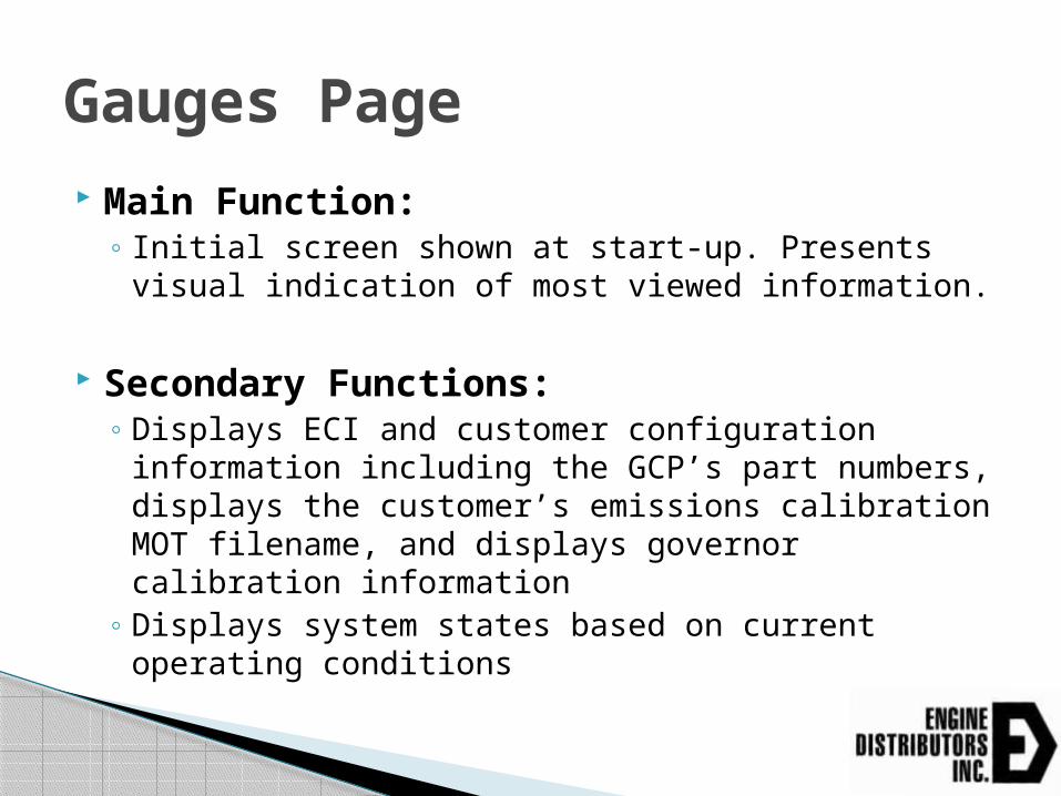
Main Function: Initial screen shown at start-up. Presents visual
indication of most viewed information.
Secondary Functions: Displays ECI and customer configuration
information including the GCP’s part numbers, displays the customer’s emissions calibration MOT filename, and displays governor calibration information
Displays system states based on current operating conditions
Gauges Page

Gauges page

EDI part #
Calibration #
Displacement
Engine Part #
Firing order

Calibration #EDI Ford Calibration Identification Key
Model, Customer and Base Cal # Quick Reference Parameters
# # # # X # # X XX X # X#
Module OEM (EDI REFERENCE)EngineModel
Option 1 Option 2 Revision -- Fuel -- Control Type --
Speeds idle(optional),
max-- MISC
Fuel Control Type
Module # Type of Module Manufacturer GAS FP - Foot Pedal 1 EPM Econtrols LP HT - Hand Throttle 2 L series Woodward NG TAPUD - Tap Up/Down
3 GCP Econtrols DF( Gas/LP) DIS - Discrete Speed
TSC1 - J1939 CAN Control FIXED - Goes directly to set RPM
(Genset)
Engine Model Engine Model D DSG 423 T TSG 416 E ESG 642 W WSG 1068 M MSG425
Notes: Example Engines from December 2012 and beyond will follow the
above labeling system.
3125M13B_NG_TAPUD_2100 Explanation
Customer # 125 has an MSG425 on natural gas with tap up/down control up to 2100 RPM.
Engines prior to December 2012 and large volume OEMs that have standardized calibrations will follow the "Model,
Customer, Base Cal #" system
*Also located on GCP sticker
Main Function: Displays raw voltage feedback from GCP inputs
and outputs.
RawVolts Page


Aux_DIG1 volts – Fuel select; 12 volts, gnd, open Aux_DIG3 volts – Brake input if used TPS1_Raw volts – Throttle position sensor 1 voltage TPS2_Raw volts – Throttle position sensor 2 voltage FPP1(2)_raw – Foot pedal (1 & 2) input voltage Gov1_raw – Governor 1 input; 12 volts (engage), 0 volts (ground) or 2
volts (open) Gov2/DIG4_raw - Governor 2 input; 12 volts (engage), 0 volts (ground)
or 2 volts (open) Oil pressure voltage – Reference voltage; 5 volts = open, 0 volts = ok MAP_raw – Sensor is 0 volts if open, 0-5 volts when operating ECT_raw – ECT/CHT Sensor is 5 volts if open, 0 -5 volts when operating IAT_raw - Sensor is 5 volts if open, 0 -5 volts when operating Aux_PWM3 – Gasoline fuel pump ground control Aux_PU1 – Gasoline fuel block temperature voltage Aux_PD2 – Gasoline fuel block pressure voltage
Key Rawvolts Page Parameters

Main Function: Displays information generally used during fault
detection and provides fault code interaction.
Historic and active faults are displayed here
Provides some variables to aid in diagnosing faults
Can clear the faults from this page as well
Faults Page

Figure 32: Faults page
Engine Speed – Reading from the crank sensor Manifold Pressure – Pressure reading from intake manifold; typically 4 to 14psia depending on
load Barometric pressure – Reading from MAP sensor at key on; typically 14.7psia Coolant temperature – Direct reading from ECT sensor or estimation from CHT Cylinder head temp – Direct reading CHT if equipped Intake air temperature – Reading of the manifold intake temperature from TMAP sensor Spark Advance – Shows current timing of ECU, preset in ECU Fuel rail pressure – Pressure reading from gasoline fuel block Fuel temperature – Temperature reading from gasoline fuel block Gaseous pressure target – DEPR target output pressure to mixer Gaseous pressure actual – DEPR actual output pressure to mixer; should match target Current governor target – Engine speed ECU is trying to achieve Engine load; torque – Estimation of % load/torque based on MAP, Engine speed, etc. Vbattery – Battery voltage value into GCP; should equal battery voltage Vswitch – Ignition voltage from keyswitch; voltage at start/running, zero volts at shutdown Hour meter – current engine hours logged by ECU MIL-total on time – Amount of hours engine ran with MIL on Cumulative starts – Amount of start attempts made on engine
Key Faults Page Parameters

EG01 – Pre-catalyst O2 sensor voltage; switches between 0-1.0 volts Closed loop 1 – shows fueling accuracy, 0 = stoichiometric; typically will switch
between negative (rich) and positive (lean); +/-1%. Adaptive 1 – Where the fueling correction is added to the ECU permanent memory.
If closed loop 1 goes more than +/- 1% for a certain amount of time. Compensates for manufacturing tolerances in the engine assembly.
EGO2 – Post catalyst sensor voltage; typically ~1 volt OL, 0.8 volts CL TPS Command – Throttle position ECU is commanding TPS Position – Actual position of the throttle, should match the command TPS1 percent – throttle position sensor 1 % open TPS2 percent – throttle position sensor 2 % open TPS1 voltage – Voltage value of the throttle position 1 TPS2 voltage – Voltage value of the throttle position 2; TPS1 and TPS2 = 5 volts
added together FPP Command - % of the foot pedal being registered by ECU FPP Position - % of the actual foot pedal position FPP1 Voltage – Voltage input of foot pedal, 0.2 to 4.8 volts FPP2 Voltage - Voltage input of foot pedal 2, 0.2 to 4.8 volts IVS Voltage – Voltage of the IVS switch from foot pedal
Key Faults Page Parameters 2
Run Mode – Shows the current engine state; stopped, cranking, running Power Mode – Key Off, Standby, Active Fuel Type – Current fuel type the ECU is set too; Gasoline, Propane, Natural
Gas Fuel supply – On or off Fuel Control Mode – Showing if the system is open loop, closed loop, or
closed loop with adaptive learn Active governor mode – Isochronous or droop, typically all EDI engines are
isochronous Oil pressure state – low, low-ignored, OK Oil Pressure config. – Ground = Ok, or visa versa Gov 1 Voltage – Governor 1 input; 12 volts (engage), 0 volts (ground) or 2
volts (open) Gov 2 Voltage - Governor 2 input; 12 volts (engage), 0 volts (ground) or 2
volts (open) Oil pressure voltage – Reference voltage; 5 volts = open (low or off), 0 volts
= closed (ok) MAP Voltage – Sensor is 0 volts if open, 0-5 volts when operating ECT/CHT voltage – Sensor is 5 volts if open, 0 -5 volts when operating IAT voltage - Sensor is 5 volts if open, 0 -5 volts when operating
Key Faults Page Parameters 3

Spark kill – On gasoline only coils can be disabled to locate a possible bad coil; #s listed is firing order
Injector kill - On gasoline only fuel injectors can be disabled to locate a possible bad injector; #s listed is firing order
DBW test – To test the throttle body by verifying if it goes to commanded position, KOEO, sends the throttle to 0% position.
External power – KOEO; Auto (standard ECU control), Relay On (turns power relay on), All On (turns power relay and fuel pump relay on)
De-rates/Warnings – Shows if a code is forcing a de-rate, idle, or other condition onto the engine.
Snapshot / Flight data base definitions – Shows defaults settings as well as custom definitions that can be added
Historic Faults – All of the faults that have occurred on the engine, can only be cleared via the GCP display software
Active fault – Only shows faults that are currently active on the engine. Once issue is corrected this fault will disappear and only be listed as historic.
Key Faults Page Parameters 4

Monitored Drivers Injector-on low-side voltage
0 volts all times Injector-off low-side voltage
12 volts when running 0 volts when unplugged or off
Coil Driver Spark dwell [ms] Preset Values in ECU– based on system voltage
Key Faults Page Parameters 5

Two sets of data are recorded Fault snapshot and Flight data recorder
All the variables recorded for each can be seen on the bottom right of the faults page
Double click red light next to fault code
Viewing a Fault

After double clicking this page comes up Can clear the fault or view the Snap Shot Data or
the Flight Data Recorder
Viewing a Fault

SSD and Flight Data Recorder
Diesel/Contaminated fuel introduced into the gasoline system Clean lines/fuel rail, replace injectors, block filter and pump
Low power on a natural gas Genset Typically not enough fuel pressure to the engine
No start, no codes present Typically fuel related issue
High gasoline fuel pressure; code 1561 Bad fuel block or fuel was grounded directly (normally PWM
controlled) O2 sensor failure; code 134 or 154
Improper mounting from installation Liquid being introduced into the
Bricked GCP (Bootstrap Mode) User lost power or unplugged the COMs cable while programing
Common Issues

On the Flash Drive Engine Wiring Schematics Panel Wiring Schematics GCP Diagnostic Manual J1939 to DTC Fault Code List Service Manuals Parts Manuals Warranty Information
Important Service Documents to Have

Questions???