By Katy Thompson Section 6 11-27-12 - Stewart...
13
Theremin By Katy Thompson Section 6 11-27-12
Transcript of By Katy Thompson Section 6 11-27-12 - Stewart...
Theremin
By Katy Thompson
Section 6
11-27-12

1
Introduction
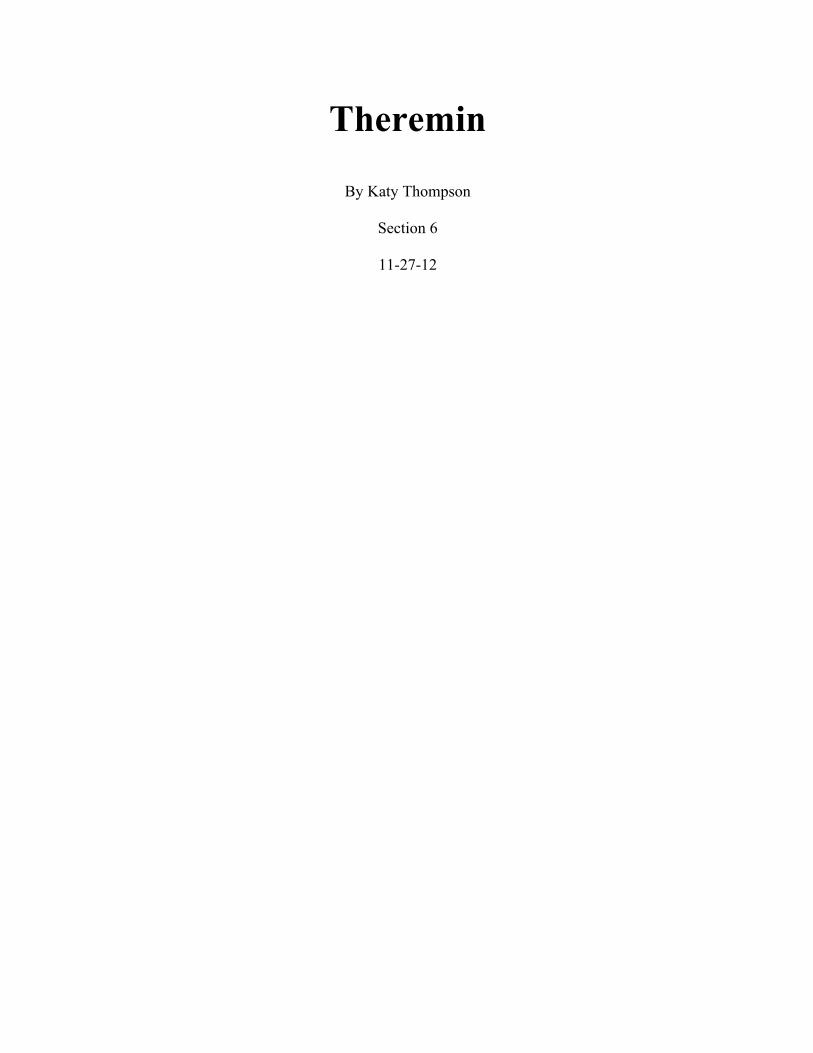
The theremin, invented in 1919 in the Soviet Union, is considered one of the first
fully developed electronic musical instruments. It was named after its creator, the
physicist Lev Sergeyevich Termen, or Leon Theremin. (History Lesson) This instrument
gets its recognition from the uniqueness and originality behind it. The original basic
structure consists of a wooden box fitted with two radio-frequency oscillators and two
metal antennas, a vertical rod on the instrument's right and a horizontal ring on its left.
The vertical antenna controls the pitch and the horizontal controls the volume. It’s unique
because of the ability to play this instrument without any physical contact. Just by waving
a hand in front of each antenna, a player can produce many different sounds and tones.
The theremin has been incorporated in music anywhere from the early orchestra to
popular music of today. (Columbia Electronic Encyclopedia)
History
Theremin’s invention began the emergence of electronic music. In 1915 Lee De
Forest invented the oscillator, which revolutionized the radio industry. In turn Theremin
used this new technology to revolutionize the music industry. He travelled all through
Russia demonstrating his device on the invite of Lenin. In 1926 he arrived in Europe
where audiences especially in Germany, France, and England praised him. Critics
claimed his instrument as a transformation of the world of music. (Glettler) This
excitement and his sensational performances commenced Theremin’s international
recognition. In 1927, he made his way to the US. To promote his instrument he trained
many musicians in his New York studio to be able to play the theremin in order to bring

2
it into the public eye. His best student Clara Rockmore has been considered the best
thereminist ever with unparalled precision by developing her own aerial fingering
techniques. Theremin ended up selling his patent rights to the Radio Corporation of
America. From 1927 to 1931 they manufactured and sold 500 instruments. He abruptly
left in 1938 under the Soviets demand. While in solitude he worked in a special lab under
the Internal Affairs department of the Soviet Union. After his release he was given the
Stalin Prize in 1947. Many compared this prize to the Nobel Prize of the USSR. He
received his award for his espionage devices that could easdrop on US embassies.
(Glinsky) “Some of the bugging devices were so advanced that the U.S. did not discuss
them until 1960, over ten years since their discovery.” (Mattis) He did not return to the
United States until 1991. Two years later he died right after an American documentary
premiered about his life, “Theremin, An Electronic Odyssey” (TVOX) His musical
device had left his legacy and imprint across the globe.
This musical instruments commercial downfall was due to its best feature,
complete freedom. Many compared it to “singing with someone else’s voice” and could
not master it. However others took note of this and attempted many of their musical
aspirations. Its unique eerie and haunting sounds are difficult to replicate. This device has
been involved across the board in the entertainment industry from its background music
in “The Bride of Frankenstein” to its use in Led Zeppelin’s songs.
3
Figure 1. Modern Day Theremin vs. Original theremin
Components of the Theremin
LC Circuit Tank
The simplest form of sound is just a wave produced by something oscillating.
This motion can be described as a function of sine. How fast an object takes to complete
one full cycle of oscillation, from its starting point and back again, with respect to time is
its frequency. This movement, or vibration, is characterized as simple harmonic motion.
(SHM) In nonelectric musical instruments there are objects that perform SHM. For
example, the strings on a piano or the air inside a flute are the vibrating objects. (Berg)
Well in electrical instruments, an electric oscillator replaces these objects. This is a
device that generates electric currents or voltages in this motion by nonmechanical
means.
An LC circuit tank acts as the electric oscillator in a theremin. This type of circuit
consists of an inductor (L) and a capacitor (C). An inductor is an electric component,
usually a coil, that when current passes through it produces a magnetic field. And a

4
conductor is a device used to store an electric charge. At certain frequencies the
combination of the two produces a “resonant” circuit that outputs a resonant frequency.
(Zhu) This is when the inductance and capacitance reactances are equal and cancel. This
only leaves the resistance of the circuit to oppose the flow of current. (Skeldon)
The LC circuit tank can be described using figure 1 below. The capacitor stores
its energy as static voltage and the inductor stores its energy in the form of an
electromagnetic field. The capacitor is charged up by a voltage supply by moving the
switch to A. Once fully charged the circuit switches back to B where the capacitor begins
to discharge causing all the energy to be stored as the electromagnetic field. As soon as
there is no more voltage to maintain a current, the magnetic field begins to collapse. This
induces an emf keeping the current flowing back to the original direction. This process
theoretically continues back and forth producing a sinusoidal voltage. (Glettler) This
action mimics the physical motion of oscillation.
Figure 2. Representation of the LC Circuit (Storr)

5
Vacuum Tubes
LC tank circuits need to be “recharged” sometimes. This is because resistance
exists in the inductor, capacitor, and the wires. In the original design of the theremin,
vacuum tubes were used to keep the LC tank circuit oscillating. Versions of this
invention were matured and patented by Lee De Forest in 1907. The tube is said to have
started the revolution of electronics. (History Lesson) A vacuum tube is basically a
heated cathode, plate, and a grid. Electric potential is applied to both the cathode and
plate. When the plate is more positive, electrons jump from the cathode to the plate. This
acceleration of the electrons form an electric current. However this current can only go
one direction. The effect of the grid allows the tube to operate both as a current switch
and a voltage controlled current amplifier. (Simonton) The vaacum tube, or valve, is
replaced today by transistors.
Capacitance
The resonant frequency of an LC oscillator can be mathematically expressed by
the equation !! =!
!! !". (Glettler) In order to change the frequency of an LC oscillator,
then one of its variables needs to change. Among the capacitance or the inductance,
capacitance is the easiest to change. As we learned earlier in the semester the capacitance
depends on both the distance between the conductors and the area of their surface. The
human body and the antenna are the conductors in the theremin’s case. The movement of
the theremin player’s hand near the antenna changes the capacitance therefore it stands to
reason it changes the resonant frequency also. However this change does not make a very
significant effect. The change of capacitance can result in as little as a few picofarads.
6
With that said for a device to be feasible, the oscillator frequency must be arranged to
operate upwards of 500kHz. At this higher frequency even just a 1% change in the
capacitance can change the resonant frequency by around 5kHz. (Skeldon) This could be
a very significant change in the musical scale.
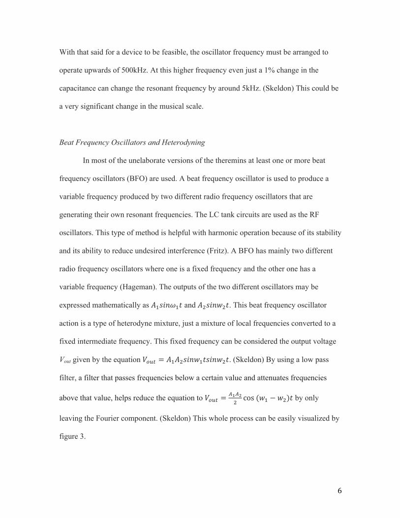
Beat Frequency Oscillators and Heterodyning
In most of the unelaborate versions of the theremins at least one or more beat
frequency oscillators (BFO) are used. A beat frequency oscillator is used to produce a
variable frequency produced by two different radio frequency oscillators that are
generating their own resonant frequencies. The LC tank circuits are used as the RF
oscillators. This type of method is helpful with harmonic operation because of its stability
and its ability to reduce undesired interference (Fritz). A BFO has mainly two different
radio frequency oscillators where one is a fixed frequency and the other one has a
variable frequency (Hageman). The outputs of the two different oscillators may be
expressed mathematically as !!!"#$!! and !!!"#$!!. This beat frequency oscillator
action is a type of heterodyne mixture, just a mixture of local frequencies converted to a
fixed intermediate frequency. This fixed frequency can be considered the output voltage
Vout given by the equation !!"# = !!!!!"#!!!"#$!!!. (Skeldon) By using a low pass
filter, a filter that passes frequencies below a certain value and attenuates frequencies
above that value, helps reduce the equation to !!"! =!!!!!cos (!! − !!)! by only
leaving the Fourier component. (Skeldon) This whole process can be easily visualized by
figure 3.

7
Figure 3. Module of the Beat Frequency Oscillator System (Skeldon 946)
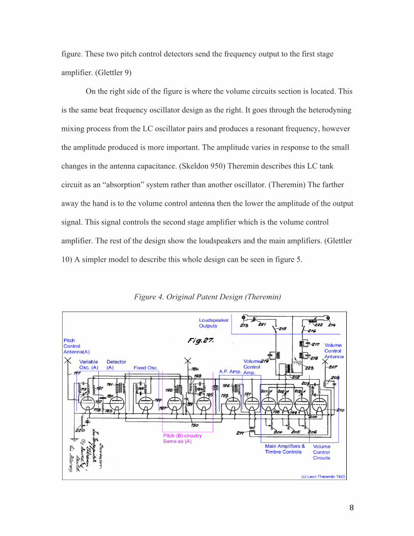
Original Analog Theremin Design
Now that we understand the main components of the theremin we can look at the
whole design of the original schematic of the U.S. patent in 1928. In figure 4 is the edited
schematic for Leon Theremin’s original design. It illustrates the complete system for
producing the musical sounds and tones and in the actual patent it describes each
characteristic thereof. (Theremin US)
On the left side of the figure is the pitch control circuits section. There are 2 LC
tank oscillators on this side. Earlier we discussed how usually in a beat frequency
oscillator there are two resonant frequency oscillators, where one has a fixed frequency
and the other has a variable frequency. The LC tank oscillator closest to the antenna is the
variable oscillator. The frequency of this oscillator depends on the player’s hand. Two
sections over is where the fixed LC oscillator is where the frequency is the same. These
two signals are mixed, which is the previously described process of heterodyning. The
heterodyning signal is then picked up by the detector located in between the two
oscillators. There is also another identical pitch control section in the middle of the
8
figure. These two pitch control detectors send the frequency output to the first stage
amplifier. (Glettler 9)
On the right side of the figure is where the volume circuits section is located. This
is the same beat frequency oscillator design as the right. It goes through the heterodyning
mixing process from the LC oscillator pairs and produces a resonant frequency, however
the amplitude produced is more important. The amplitude varies in response to the small
changes in the antenna capacitance. (Skeldon 950) Theremin describes this LC tank
circuit as an “absorption” system rather than another oscillator. (Theremin) The farther
away the hand is to the volume control antenna then the lower the amplitude of the output
signal. This signal controls the second stage amplifier which is the volume control
amplifier. The rest of the design show the loudspeakers and the main amplifiers. (Glettler
10) A simpler model to describe this whole design can be seen in figure 5.
Figure 4. Original Patent Design (Theremin)

9
Figure 5. Model of Theremin design
Conclusion
The design described in this paper is just the analog version of the theremin.
Unfortunately trying to replicate the original theremin can be very difficult and
expensive. Many of the original components aren’t used in everyday life now so that is
where the project becomes a little pricey. With today’s modern day technology, many
different modified versions of the theremin do exist though. The range of size and
complexity is very broad from anywhere to digital designs to optical designs.
Instead beat frequency oscillators digital designs use CMOS oscillators. These
produce different DC levels. One varies with the distance between the pitch antenna and
the hand and the other with volume antenna. The advantages behind this design are that
the DC levels are able to control a filter involving voltages. This makes the sound much
higher quality (Skeldon).
Optical designs are different because it creates the audio frequency directly
instead of operating a circuit to do so. However to do this it is useless to change the
capacitance. The resistance has to change by using photocells. These are light dependent
resistors. This theremin depends on the amount of light from the photocells rather than
the distance from the antennas.
10
As simple of an instrument the theremin was, it started a revolution not only in the
world of music, but in the world of science also. From the early 1920’s when it made its
way across nightclubs and orchestras to the horror and sci fi movies in the 1960’s. This
instrument was a cornerstone for many things. Theremin’s technology behind his
invention opened many doors for other scientists as well.

11
Bibliography
1. Berg, R.E. and Stork, D.G. “The Physics of Sound.” Burgess Reviews. 2nd Edition.
2. "Capacitive Touch Sensors." 2009.Machine Design 81 (3): 45-45. http://0-
search.proquest.com.library.uark.edu/docview/217193766?accountid=8361.
3. Fritz, Langford-Smith. Radiotron's Designer Handbook. 4thth ed. N.p.: University of
Virginia
4. Glettler, James. M.I.T., “Theremaniac Bringing Leon Theremin and his instrument
from the twenties to the twenty first century.” Last modified 2002. Accessed
October 3, 2011
www.mit.edu/~glettler/resume/undergrad/phys489_Theremaniac.pdf
5. Grimes, Gerlinda. "How a Theremin Works." How Stuff Works.
http://electronics.howstuffworks.com/gadgets/audio-music/theremin2.htm.
6. Hageman, Rachel and Steve Hageman. 1997. "Metal Detector Uses Single IC." EDN
42 (26): 94-96. http://0-
search.proquest.com.library.uark.edu/docview/222393291?accountid=8361.
7. "History Lesson [the Vacuum Tube]." 2000.CIO Canada 8 (3): 12-12. http://0-
search.proquest.com.library.uark.edu/docview/217421078?accountid=8361.
8. Max ‘Whiskers.’ “Maxies Pages - sitemap.” Maxies Pages.
9. "Theremin." Columbia Electronic Encyclopedia, 6th Edition 1. 2011.
10. THEREMIN, LS. "THEREMIN." U.S. Patent 1,658,953, issued February 14, 1928.
11. Simonton, John. “PAiA: How Tubes Work.” PAiA.
http://www.paia.com/tubworks.htm
12
12. Skeldon, Kenneth D., Lindsay M. Reid, Viviene McInally, Brendan Dougan, and
Craig Fulton. "Physics of the Theremin." American Journal of Physics 66 (1998):
945.
13. Storr, Wayne. "LC Oscillator." Basic Electronics Tutorials. http://www.electronics-
tutorials.ws/oscillator/oscillators.html.
14. Web Design Cochin. "Beat Frequency Oscillators (BFO)."
http://www.circuitstoday.com/beat-frequency-oscillator-bfo.
15. Zhu Liying; , "Modeling and dynamics of switching electrical LC-circuits," Control
Conference (CCC), 2011 30th Chinese , vol., no., pp.1555-1559, 22-24 July 2011
URL:http://ieeexplore.ieee.org/stamp/stamp.jsp?tp=&arnumber=6001081&isnumbe
r=6000362