By Authority Of - Public.Resource.Org · drostatic test pressure, as well as the stresses...
26
By Authority Of THE UNITED STATES OF AMERICA Legally Binding Document By the Authority Vested By Part 5 of the United States Code § 552(a) and Part 1 of the Code of Regulations § 51 the attached document has been duly INCORPORATED BY REFERENCE and shall be considered legally binding upon all citizens and residents of the United States of America. HEED THIS NOTICE : Criminal penalties may apply for noncompliance. Official Incorporator : THE EXECUTIVE DIRECTOR OFFICE OF THE FEDERAL REGISTER WASHINGTON, D.C. Document Name: CFR Section(s): Standards Body: e
-
Upload
truongtuyen -
Category
Documents
-
view
214 -
download
0
Transcript of By Authority Of - Public.Resource.Org · drostatic test pressure, as well as the stresses...

By Authority OfTHE UNITED STATES OF AMERICA
Legally Binding Document
By the Authority Vested By Part 5 of the United States Code § 552(a) and Part 1 of the Code of Regulations § 51 the attached document has been duly INCORPORATED BY REFERENCE and shall be considered legally binding upon all citizens and residents of the United States of America. HEED THIS NOTICE: Criminal penalties may apply for noncompliance.
Official Incorporator:THE EXECUTIVE DIRECTOROFFICE OF THE FEDERAL REGISTERWASHINGTON, D.C.
Document Name:
CFR Section(s):
Standards Body:
e
carl
Typewritten Text
American Society of Sanitary Engineering
carl
Typewritten Text
24 CFR 3280.604(b)(2)
carl
Typewritten Text
carl
Typewritten Text
ASSE 1001: Performance Requirements for Pipe Applied Atmospheric Type Vacuum Breakers

., •••• - 'f
ASSE *10U1 88 8M U(~~~(~ UUUUUU( ,
A.S.S.E. Standard No.1 001 Issued: May, 1966
Performance Requirements for
PIPE APPLIED ATMOSPHERIC TYPE VACUUM BREAKERS
. Revised:' Oct., 1970 ANSI No. A112.1.1-1971
Revised: July, 1981) ANSI Approved 1990 ~
• Sponsored by: American Society of Sanitary Engineering
AMERICAN SOCIETY OF SANITARY ENGINEERING p.o. Box 40362 - Bay Village,.OH44140 Phone: 216-835-3040 - FAX: 216-835-3488
/"Tr"In1:rnTr1rTfT1 'I!. ___ ': ___ 1"1 __ .! _ .L ___ r.... '.


General Information
Neither this standard, nor any portion thereof, may be reproduced wi thout the written consent of the American Society of Sanitary Engineering.
Al though this standard may be used as a benchmark for in-house product evaluation, no product may be said to be A. S. S. E. approved unless the manufacturer has applied to the A. S. S. E.. has had his product test.ed by an official A. S. S. E. recognized independent laboratory, according to. the applicable A.S.S.E. Standard, and when the product has passed the test, displays the A. S. S. E. Seal on the product. Instructions· for receiving the authorization. to display the Seal are available from the A. S. S. E. Central Office.
It is recommended that all devices designed for . plumbing systems, especial! y those which pertain to public health and s:afety. should be installed consistant with local codes by qualified and trained prof~ssionals.
American Society of Sanitary Engineering
© Copyright ,966 © Copyright ,988
COPYRIGHT American Society of. Simitarv Enain",,,,r;na

Foreword
Standards for the components of Plumbing Syst~ms are consldered by the American Society of Sanitary Engine,ering (A.S.S.L) to be of prime importance in the development of improvedplumbinS ~ystems and for the increased protection of public health and safety.
To accomplish this the A.S.S.E. is enco~rogtng manufacturers to cooperate with its standards Committee to develop and revise standards for performance and testing procedures for their prQducts that will have the endorsement of the manufacturers and still be acceptable by the society.
Realizing the need for a uniform Standard and Test PrQcedure. that manufact~rers and laboratory personnel could.follb~ to test a~d evaluate the performance of anti-siphon vacuum breakers,theA.S.S.E in 1958 formed a committee consisting of the Directors and personnel of the plumbing testing laboratories of Chicago,Detroit and-Los Angeles I as well as a representative of the Bureau of Water Register of the New York City Department of Water Supply, to develop such a standard. Through the _ Standards Committee,- with the cooperation of interested manufacturers, there was developed the following Standard of Performance Requirements .and Test Methods for Pipe-Applied, Atmospheric Type, 'Anti-Syphon Devices (hereinafter referred to as vacuum breakers) for installation in potable water supply systems.
At the 1962 Annual Meeting of the Society held in LittieRock, Arkansas, the work of the committee culminated in the acceptance of this standard and assigned the official number 1001. Since that time, Standard 1001 has been revised in 1970, 1980, and 1988.
Although many of the material specificati9ns are_ detailed within Section 1.4 of this Standard, it is the responsibility of the manufacturer to comply with the requirements of the Safe Drinking Water Act, United States Public Law 93-523. -
If there are comments or suggestions regarding standard 1001, pleaSe submit them to Dr. Stuart F. Asay, P.E.,Ph.O.,~.S.S.E. Standards Coordinator, 11166 N. Huron, Unit 29, Northglenn,- CO 80234. (503) 451-0978, FAX (303) 452-9776.
COPYRIGHT American Society of Sanitary Engineering

A~~I:. *.1UU.1 88 _ U'~'1'1h~ UUUOD1D 9 _
1988 - A.S.S.E. Standards committee Members
Stuart F. Asay, P.E., Ph.D. A.S.S.E. StandardsCoordinato~
Northglenn, Colorado
Robert C. Smith, P.E. Standards Committee Chairman'
Tulsa, Oklahoma
Joe Adam Washington, DC
Sid Cavanaugh Alta Loma, California
Patrick J. Higgins Frederick, Maryland
Morris Weinberg, P.E. Atlantic City, New Jersey
Julius Ballanco L P.E. <?ountry Club Hills, Illinois
William Gallagher ~ittsb~rgh. Pennsylvania
Sterling Neblett Houston; Texas·
Working group members for the revision of the ASSE backflow prevention device standards.
Stuart F. Asay, P.E., Ph.D.,ChQi~ A.S.S.E. Standards Coordinator.
Northglenn, COlorado .
Rand fl. Ackroyd Watts Regulator Company
North Andover, Massachusetts
Dick Breneman Woodford Mfg. Co.
Colorado Springs, Colorado
Wil1iam Dunmire FEBCO
Fresno, California
Leo Fleury Grinnell Corporation
Cranston, Rhode Island
Richard G. Myers Ford Meter Box Co.
Wabash, Indiana
Bob Purzycki 8ackflow Apparatus & Valve Co.
Gardena, California
George H. Swenson Conbraco Industries, Inc. Matthews, North Carolina
COPYRIGHT American Society of ,'ian; t-arv Rnrdn",,,,r;nn
.. led 8eyke ·Honeywell
.ScarboroyghjOntario; Canada .
Bernie Clarke 8ackflowPrevention Device Tester
Valencio,California
_ LesEngelmqnn Ames Company, Inc.
Woodland Park,California
_ 10m Konen, P.-E. Stevens Institute of Technology . Hoboken, New Jersey
Brad l. Nol1 Wilkins Regulator Co.
Paso Robles, California
Robert E. Sands Mueller Company
Decatur, Illino~s

1 .. 1
1.2
1.3
1.4
1.5
A')')t. +JlUUJI 00 - ... I ...... - ------- -
PIPE APPLIED ATMOSPHERIC TYPE VACUUM BREAKERS
SECTION I
General Construction .. . " . . . . . . . . . . . . . . . . . .1
1.1.1 Class of Devices . 1
1 . 1 .2 Sizes . . . . . . . . . . . . . . . . . . . . . . . . . . . . 1 1.1.3 Working P~essure ....•................. 1
,. 1 .1.4 Temperature Range . . . . . . . . . . . . . . . . . . . . . .1
Purpose ... . . . . . . . . . . . . . . . . . . . . . . .1
Limitation of Design
1 .3. 1 Flow Capacity . . . . . . . . . . . . . . . . . . . . . . . . 1 1.3.2 Air Port Shi~lds ...................... 1 1.3.3 Air -Port Opening Area .1 1 . 3( 4 -Structural Strength . . 1.3.5 Mechanical Function ..
.2
.2
.2 1.3.5.1 Durability 1.3.5.2 1.3.5,.3
1.3.5.4
1.3.S.5 1.3.5.6
1.3.5.7 1.3.5.8,
1.3.5.9
1.3.5.10
Chatter or Vibration .2 Water Hanuner . . . . .2 Unaffected by Line Surges . . . . . . . . . . . 2 Leakage - Low Pressure .2 Moving Part Clearances ............. 2 Action Under Vacuum 2 Leakage . . . . 2 Misassembling . . ,. 2 Female Threaded Connections 2
Materials . . . .2
.2
.3
.3
1.4.1 Reference Standards 1.4.2 Toxic -Mat'erials ..
Dissimilar Metals . 1.4.3
1.4.4
1.4.5 1.4.6
Bodies and Internal Non-Cast Parts . . . . . . . . . . . . . 3 Valve discs, Seat-facings, etc ................ 3 Metal to Metal Seating of Check Valves 3
1.4.7 Pipe Threads ... . 3
Instructions for Marking and Installation . .. 3
COPYRIGHT American Society of Sanitary Engineering

2.0 2.1
2.2 2.3
2.4
2.5 2.6
2.7
2.8
2.9
3.0
Table Table Table
1 .5.1 Marking af Devices . . . . . . . . . . _. . . . . ',' 3 1 .5.2 Installation Instructions . . . . . . . . . . . . .. . . . .4 1.5.3 Installation Recommendations. . . . . . .. . ..•... 4
SECTION II
CRITERIA AND PROCEDURES FOR EVALUATION . . . • . . . . . .. . . . 5 Drawings. . . . . . .5 Laboratory Testing ....................•.... 5 Noise .................. ' ..•. ' ......... 5 Hydrostatic and Air Inlet Test of' Complete. Devi.ce .. . . -. . .5 Deterioration at Extremes of Manufacturer's rempe.rature Range Allowable Pressure Loss at Rated Flow . • . .. , • 'I· • •
.5
.6 Air Port Shields ...........••. ' ........... 7 Air Flow Test . Water Rise Test
SECTION III
Definitions . . . .
LIST OF TABLES AND ILLUSTRATIONS
1 Hot Water Flow Rates for Testing. '.' •..
.7
.8
.' " .' .....• 14
••••• 6
2 Required Rated Flow and Maximum Allowable Pressure Loss .7
.9 3 Fouling Wire Diameters. . . .. .. ,;; ..
Figure Vacuum Breaker Hookup . Fouling Wire Replacement. Fouling Wire Replacement. Fouling Wire Replacement. Vacuum Tank Test Hookup • Setup for Hot Water Testing
.8
.9
10
10
11,
12
Figure 2
Figure 3
Figure 4
Figure 5
Figure 6 ..
COPYRIGHT American Society of SanitarY Enaineerina
1 . 1
1 .1.1
1.1.2
1.1. :5
1.1.4
1.2
1.3
1. 3.1
1.3.1.1
1.3.1.3
1.3.1.4
1.3.2
1.3.3
A.S.S.E. Standard No. 1001 Revised: August. 1988
PIPE APPLIED ATMOSPHERIC TYPE VACUUM BREAKERS
SECTION I
GENERAL - CONSTRUCTION
Class of Devices
Vacuum breakers, other than air gaps, may be classified into two general types:
(1) AtmospheriC ty~e, (2) Pressure type (See A.S.S.E. Standard 1020.)
The design consists of a check valve member and an air vent that is normally closed whe~ the device is pressurized and open when the inlet pressure is atmospheric.
~hi~ standard applies only to those devices classified as "atmospheric-type" that are single pipe-applied and does not apply to tank ball cocks or similar devices that depend on float operated valves to control flow.
Sizes - Inlet and outlet pipe sizes one-quarter inch (1 /4") to four inch (4").
Working Pressure - Devices shall be designed for a working pressure of at least 125 p.s.i. (862 kPa) but not less than 8 p.s.i. (55 kPa). -
Temperature Range
(a), Cold Water Service: From 33 degrees Fahrenheit (0.55 degrees Celsius) up -to 110 degrees Fahrenheit (43 degrees Celsius).
(b) Hot Water Service: From 33 degrees Fahrenheit (0.55 degrees Celsius) up, to 180 degrees Fahrenheit (82.2 degrees Celsius) minimum. -
Purpose - To prevent backflow or back-siphonage into a potable water distribution system when installed with the Critical Level point (as described later herein) at least 6 inches above the flood level rim of the receptacle served or greatest elevation of use, and when installed on the disc harpe side of the last control valve, and th~backflow source is subJect to no more than normal atmospheric pressure. This device shall not be subjected to more than twelve (12) hours 9f continuous water pressure.
Limitations on Design
Flow Capacity'
The water passageway through the device shall be of sufficient size to deliver the required volume rate of water to any fixture or receptacle served.
Flowways shall be designe,d to reduce cavitation and to meet the pressure loss requirements of this standard.
Interior Finish -The interior of the device shall be reasonably smooth and free of burrs.
Air Port Shields - Air ports of vacuum breakers shall be shielded so as to minimize the probability of port fouling. Air port shields shall extend down the body of the device, over the air ports, to the ',lowest p'orti_on ~ of the air ports, and shall maintain a minimum 3/16" (4.8 mm) clearance between the inner lower edge of the shield and the lowest surface plane of the air ports.
Air Port Openin~ Area - The size and positioning of the air ports shall be effect1ve in admitting a volume rate of air flow through
~
C:OPYRIGHT American Society of Sanitary Engineering Page 1

1.3.4
1.3.4.1
1:3.4.2
1.3.5
1.3.5.1
1.3.5.2
1.3.5.3
1.3.5.4
1.3.5.5
1.3.5.6
1.3.5.7
1.3.5.8
,",~..,)L.. ~..uuu.u uu _ '-', .... I • 1_
A.S.S.E. Standard No~ 1001 . Revised : August, 1988
the air ports into the discharg.a outlet of -the device equal to' or ~reater than the volume rate of air flow obtainable through :the l.nlet water passageway of the devic~ -in~o the discharge outlet under conditions of equal yac.uum appl~catl.ons.
Structural strength
All parts of the devits shall be designed to withstan~ ~ithout permanent distortion, the . stresses .. developed by the spe<;a fl.edhy-drostatic test pressure, as well as the stresses resultl.ng from a speci fied water working pressure coincident with operation under a specified unbalanced pressure condition.
Design and construction shall be such that in normal handling in transit and during installation. the device will not be damaged in any way which will prevent it from functioning as required.
Mechanical Function
The air vent must be in the fully open positio~ when the valve is at atmospheric pressure. -
Durability
(a) It is essential that devices be as trouble free as sound engineeringdesign can achieve.
(b) A reasonable planned life expectancy of. the . vacuum breaker and its parts shall be incorporated in. the' design. _
All moving parts shall be 'designed to operate up to the rated flow without objectionable chattero~ vibration ..
The operation of the device snal1 not cause water hammer.
The design shall be such that the ~erformance of the device will not be adversely affected by normal ~inepressure surges.
The air vent must not permit water leakage when the device is pressur:-ized from. atmosphericpre~sur~beyond the amoun~ of leak-age whl.ch can be contal.ned. by desl.gn .l.0 the vent area Wl. thout being visible as an external leak.
Moving part clearances shall be such.as to minimize the probabil~ i ty of immobilization in ordinary field' use. '
The device shall not permit o'water-,rise of more than 3 inches (76 mm) in a tube connected to .the outlet end of the vacuum breaker even when the. check '. member is .. held off its seat (as required in Sect~on 2.7) during varied vacuum applications ranging from 0 to 25 l. nches (0-84.5 kPa) of mercury l corrected for sea level pressure). ..' . . . .
Leakage. All joints shall be ~Qtertight where subject to water pressure.
1.~.5.9 Misassembling. The design sh61lbe suchihot ~he parts cannot be easily misassembled. .
1.3.5.10 Female pipe threaded connections· shall be. so constructed that it will not be possible to ,run a pip-einto them far enough to re- . strict the flow through the device or interfere with working parts. '. ' .. " • '... . "
1.4 Materials
1.4.1 Reference to ANSI.1 and ASTM2 Standards mean the latest edition.
Amerl.can Natl.onal Standards Institute, 14~6 Broadway, New York, NY 10018. {212} ~54-~~OO
2 American Society for Testing and Materiais,'1916 Race street. Philadelphia, PA 19103. (215) 229-5400
"- - --'---. -----
Page 2

A~~t. If:.IJUU.IJ 00 _ U I...J • I I L. ............ ---- - -
A.S.S.E. Standard No. 1001 Revised: August, 1988
1.4.2 Toxic Materials
1.4.2.1 Materials which could contaminate the water and make it injurious to pers~ns cd~sumingit shall not be used in the device where the material would be in contact with the water.
1.4.2.2 All, elastomers and polymers coming in contact with the water shall have·. characteristics that. sholl campI y wi th the Un i ted States Code of Federbl Regulations (CFR), Title 21, 177.2600, or shall be certified as non-toxic by an approved independent laboratory.
1 .4.3 ' Dissimilcir Metals - Diversity of metals in the construction of devices used in water' pipe lines is conducive to galvanic corrosion. Where di fferentmaterials are used, this action can be substontially reduced by selecting materials which are close to each other in the electromotive scale. The use of insulation may also be employed. Both expedients shall be employed to the fullest practical extent.
1.4.5 '-Bodies and internal parts shall be of material having a corrosion resistance at lea,st egu,ol to a non-ferrous alloy of not less than fi fty-eight per cent {58~) copper. ' , '
1.4.6 Valve "discs. seat facings or other non-metallic parts shall be designed for continuous ,exposure to water at the maximum rated operating temperature of the device without change in physical characteristics which would prevent fuB, compliance with all requirements efthe' stardard.
1.4.7 Metal to metal seating of r'elief means venting to atmosphere is not acceptable. Either seat. valve disc or both shall be of nonmetallic materials 'which will assure pressure tight seating and reseating.
1.4.8
1.4.8.1
1.4.8.2
1.4.8.2
1.4.8.~
1.5
1. 5.1
1.5.1.1
1.5.1.2
Pipe Threads
Taper pipe threads except dryseal shall be in compliance with St,andard ANSI lASME'5 B1. 20.1-
Dryseal shall comply with the Standard ANSI ASME 81.20.3.
Dryseal shall comply with Standard ANSI B2.2.
Other types of -, connections ~hall conform to appropriate standards.
Instructions for Marking and Installation
Marking of Devices
Each device shall have the following inf'ormation marked on it where it will be visible af'ter the device has been installed.
* ~l * d e
. f
Name of manufacturer or trademark 'Model number of the device Maximum rated working pressure Maximum water temperature for which device is designed Nominal valve size ' The direction of water flow through the devic.e
* Maybe omitted on 1/4" and 3/8" sizes.
The markings shqllbe either cast, etched, stamped or engraved on the body of the "device or on a brass or stainless steel plate securely attached to the devibe with a corrosion resistant mate-rial. '
3 Amencen $o(aety of Mechanical Engineers, United Engineering Center. 345 E. 47th Street. New York; NY 10017. (212) 705-7722
Poge 3
~OPYRIGHT American Society of sanita~y Engineering
.'
1.5.2
1.5.2.1
1.5.2.2
1.5.2.3
1.5.2'~4
1.5.3 '
1.5.3.1
ASSE *1001 88 .. 0759972 000001b T .. ;,
A.S.S.E. Standard No. 1001 Revised:. August. 1988,
In$tallation Instructions
Complete instructions for installation of the device must be packaged with the device. Drawings Or ~chematic sketches which would be useful to the installer shall be part of these instructions. These instructions must provide all information necessary to enable correct installation. The instructions shall describe or show by drawings the correct instcilled position.
Where the device is a separate unit, in the absence of ~ Critical Installation level (CIl) mark, the extreme bottom of. the body casting shall be used to d~termineits installed position. Where the device is incorporated in an outle,t tube furnished by. the manufacturer, the extreme bottom of the internal unit shall be noted on the outside of the tube by a ell line. for use in determining its installed position.
For all devices capable of being maintained or repaired in the, field. complete detailed instructions shallb"e fUrnished.
Devices shall not be subjected to continuou~ presstire for more than twelve (12) hours. This requirement shall' be included in the installation instructions.. ~
Installation Recommendations
The device shall not be installed in a concealed or inacceSSible location. nor where the venting water from 'the device during its normal functioning may be deemed objectionable.
"'\:~"'Io..
COPYRIGHT American Societv Df Sanitarv R~ainpprinn

2.0
2.1
2.2
2.2.1
2.2.2
2.3
2.3.1
2.4
2.4.2
2.4.3
2.4.4
2.5
2.5.1
2.5.2
2.5.3
SECTION II
CRITERIA AND PROCEDURES FOR EVALUATION
.u -
A.S.S.E. Standard No. 1001 Revised: August, 1988
Drawings - Assembly drawings arid other data which are needed to enable a testing agency to determine compliance with this standard, together with installation drawings, shall accompany devices when submitted for examirtation and performance tests under this standard.
Laboratory Testing
Three (3) units shall be submitted by the manufacturer of each size and model. All tests shall be run in order listed on one (1) device.
The testing agency shall select one of each type or model and size for full test. If the first valve should fail any test, a second valve shall be tested. Failure of both devices shall be cause for rejection of that type or model and size until the manufacturer has corrected the fault and submitted new devices for testing. . .
Noise - The· device shall not produce and objectionable noises when subjected to any flow rate' up to its maximum capacity, at any pressure up to its rated maximum, maintained at the inlet of the device. . . '
Conditions ~f noise shall be observed during the tests prescribed in the standard and shall be reported.
Hydrostatic and Air Inlet Test of Complete Device
The device to be tested shall be mounted in its normal working position. A control valve shall be mounted in the outlet end of the device and 'a pressure tap shall be provided in the inlet opening. The inlet supply pipe shall be connected to a water supply line whose pressure can be raised to 125 p. s. 1. (862 kPa) from the minimum wor~ing pressure. The pressure shall be raised to the rated pressure. in 25 p.s.i. (172 kPA) increments and maintained for a period of not less than five (5) minutes.
Water shall be allowed to flow freely through the device. Then the control valve at the outlet end of the device shall be closed and the water pressure in the test assembly allowed to rise to twice the rated working pressure. This pressure shall be maintained for five minutes during which time the device shall be examined for evidence of any leaks or structural deformation.
Any leaks or indications of domage shall be cause for rejection of the device.
Deterioration at Extremes of Manufacturer's Temperature Range
When exposed to water at extremes of manufacturer's temperature range, any material, whose memory is essential to the continued functioning of the device, shall not be adversely affected.
Cold water devices shall be tested at 40 degrees Fahrenheit (4-degrees Celsius) and 110 degrees Fahrenheit (43.3 degrees Celsius). Hot water, devices shall be tested at 180 degrees Fahrenheit (82 degrees Celsius) minimum or the manufacturer's maximum rated temperature, and 40 ,degrees Fahrenheit (4 degrees Celsius) .
Install the device as in Figure 6 with a heater capable of maintaining required temperature, a reservoir located above the heater, and a, pump capable of circulating' water listed in Table 1, through device continuously. The reservoir shall be vented to atmosphere. A recirculated system may be used instead of the vented reservoir at the option of the Testing Laboratory. Water
Page 5 COPYRIGHT American Society ef Sanitary Engineering

2.5.4
2.5.5
t
2.6
2.6.1
2.6.2
2.6.3
2.6.4
. -~~- ~ ... - IJ I ""' I I rc: UUUUUJJO ,j _
A.S.S.E. Standard No. 1001 Revised: A~gust. 1988
at the manufacturer's maximum rated temperature and pressure shall be circulated through the device for 8 hours per day for a total of 10 days (Total of 80 hours). Ad~quately insulate device and piping as required to maintain required temperature. through the device. After each eight (8) hour test penod, verify that the air vent returns to its fully opened position when the system pressure is reduced to atmosphere.
Run water maintained at 40 degrees Fahrenheit (4 degrees Celsius) through the device for at least one h~ur~
Any indication of change in physical characteristics of the materials which would prevent full compliance· with all requirements of this Standard shall be cause for rejection of the device.
Table 1
Size of Device Min. Hot Water FloW' inches 9m!! li.l2l-
1/4 1 0.06 3/8 2' 0.13 1/2 5 0.32 3/4 7 0.44
1 8 0.50 1 1/4 9 0.57 1 1/2 10 0.63
2 15 0.95 2 1/2 25 ·1.58
3 30 1.89 4 35 2.20
Allowable Pressure Loss at Rated Flow
The required rated water flow shall. be' obtained at or below maximum allowable pressure loss shown. in Table 2.' .
The test system shall be equipped with means for accurately measuring the rate of flow through the device Clnd indicating or recording pressures. Pressure gauges. shall be located approximately 5 pipe diameters upstream and 10 downstream of the device. The supply system shall be capable of supplying a volume of cold water adequate to meet the maximum·flow.' requirements of the device on test while SUstaining a steady inlet pressure of not less than 25 p. s. i.. Repeat attherated working pressure of· the device. .' . . ..
Purge the air from the system and then close the discharge valve. Open the supply valve fully and· gradually open. the discharge valve until the minimum required rate of flow is reached or the maximum allowable pressure 1.oss is obtained and record the data observed. Adjust for pressure loss in the piping between the gauges and the device on test. . .
Failure to achieve the minimum all.owable pressure loss shall be cause for rejection of the device. .'
Page 6 COEYRIGHT American Society of SanitarY Enain~~rina .

Table 2
A.S.S.E. Standard No. 1001 Revised: August, 1988
Maximum Allowable Pres.sure Loss Across the Device at Required Rated Water Flow
2.7
2.7.1
2.7.2
2.7.3
2.8
2.8.1
2.8.2
Size of Rated Flaw Maximum Allowable Device Pressure Loss inches ,UQ!!!. UL.tl (:!.s. i. l!5f.£L
1/4- '3 0.19 10 69 3/8 _ 6 0.38 10 69 1/2 10 0.63 10 69 3/4 17 1.07 10 69
1 28 1.77 10 69 1 1/4- 4-~ 2.84- 10 69 1 1/2 65 4.10 10 69
2 100 6.31 10 69 ,2 1/2 160 ~10.10 10 69
3 24-0 15.14 10 69 4- 4-00 25.24 10 69
Air Port Shields
Air port shiel~ishall be examined to determine if they extend down to the bottom of the lowest air port opening.
Clearances between the shield and the body of the device shall be measured to determine if an unobstructed 3/16" (4.8 mm) air passageway is.maintained.
Failure to meet either of these criteria shall be cause for rejection of the d9vice.
Air Flow Test
The device shall be subjected to tests to compare the effective throughway area from its water inlet to outlet in relation to its available internal air relief area. Tests shall be conducted as follows: -
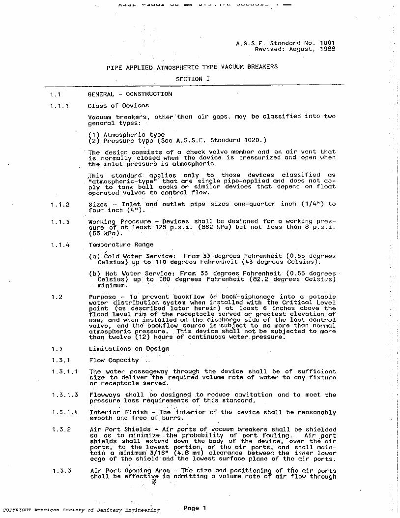
Install the device in the normal operating position with the 'check or moving member held fully open and the air valve held closed. Connect the discharge outlet of the device .by means of a 12" (30.5 em) 'length of reamed corresponding size piping to an adequdtely .izedvacuum tank capable of providing at least a 10 second air flow, and with the inlet open and a 12" (30.5 cm) reamed nipple of corresponding size threaded into the inlet (Figure 1) dissipate the vacuum in the tank from 25 inchesto 5 inches (84.5 to 17 kPa) of mercury throu9h the check valve orifice by operating a quick opening valve, t1ming the operation. See Figure 1 and Figure 5.
Page 7
COPYRIGHT American Society of Sanitary Engineeri'h'g---_________ _

2.8.3
2.8.4
2.8.5
2.9
2.9.1
2.9.2
2.9.3
PIPE APPUED A'TMOSPHERIC TYPE
VACUUM BREAKER
12 INCHES
(30.5 em)
FIGURE 1
A~S.S.E. Standard No. 1001 Revised: August, 1988
UNE TO VACUUM TANK FOR AIR
,-__ -:-_ .... _ .. _ FLOW TEST.
t~un£T PIPING
~ INLET PIPING
With the discharge outlet still ciQnn~ctedto iha vacuum tank and the inlet check held in a closed. position, hold the air valve open and dissipate the vacuum intha. tank. from 25 inchesto 5 inches (845 to 17 kPa) of mercury ~n the same manner through the air port or ports, timing the operation .. _.
The time for Section 2.8.3 shall be. equal to or less than Section 2.8.2 based on the average result of not less than three test runs, indicating that the opening(s) tQ~tmosphere is (ar~) equal to or. greater than the effective_wate~way·througl1 the device.
Failure to meet the requirements oT Section 2.8.4 shall be cause for rejection of the device.
Water Rise Test
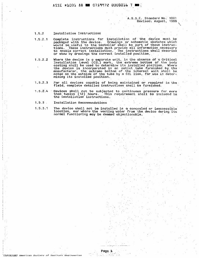
The device shall be subjected to tests ~o determine the internal reverse flow leakage should the check(s) or moving member(s) or its seat become scored. or fouled wi th a foreign substance on the seating area. The test apparatus shall conform to that shown in Figure 5. . .
To foul the check(s) or moving--member(s) of. the device, a wire shall be applied to the seat.' Wire sizes shall be a minimum of the size indicated in Table 3.
Test wires shall be furnished· by~he manufacturer, sh'aped or formed to fit the contour of the seat Or tube. The shaped test wires submitted must be in conTorrrioncewi th Table' 3. NOTE: Fouling wires mayor may not 'cause leakage.
rnDVPTr1U''T' llTno.,...';;"'.::." c,..,,',..;ot- ... , ,.."F C!.::.".;,.."' ..... ~,. 'C' ...... ,-y; ................... ; .... ,... Page -8

2.9.4
Wire Sii~d
Size of Vacuum Breaker
inches
1/8 1/4 3/8 1/2 3/4
1 1-1/4 1-1/2
2 2-1/2
, 3 4
for
Table 3
A.S.S.E. Standard No. 1001 Revised: August, 1988
Fouling Check Member
Test Wire Size Required
inches ~ 0.032 0.81 0.032 0.81 0.032 0.81 0.032 0.81 0.040 1.00 0.048 1.22 0.056 1.42 0.064 1.63 0.080 2.03 0.096 2.44 0.112 2.85 0.144 3.66
This wire sholl be placed in the lower quadrant of a suspended check( s) opposi t. e the hinge( s} or point( s) of suspension. (See Figure 2). When testing a device in which the check member(s) is (are) not hinged, but it moves vertically, the wire or spacer sholl be placed a a single point of suspension on the seating area, on center line in the direction of the outlet port, as illustrated (See Figure 3 & Figure 4). Devices having other types of moving par1!s shall have said ports spaced or defaced to accomplish the intent of this section.
FIGURE 2
.TEST WIRE TO BE PLACED ACROSS THE SEAT AT THIS POINT
Page 9
COPYRIGHT American Society of Sanitary Engineering

A.S.S.E. Standard No. 1001 Revised: August, 1988
FIGURE --3--
TEST WIRE TO BE PLACED AT POINT OF OUTlET ~
• ' ," ~ .. ,' •••• ~ ~." .:;' ,: ~ ". • :. _. - < • - • .' • • -. -
FIGURE 4
~ CHECK MEMBER
-~
_ J -
SEAT ~TEST WIRE TO _ - 8E PLACED AT
'l A'"7'?-'I!-II-----.... IIIIfIij..7!rJ _ POINT OF OUTLET
COPYRIGHT American Society of- Sanitary EnainAAr;na

18 I~ .... 5l "l
~ m 'i fo. () III b
(J) 0 () fo. m rt '<: 0 ... (J) III b fo. rt III
~ ~
!Q fo. t:1 m m 'i fo. b
!Q
""0 Q
(Q ~
.... ....
VACUUM TANK HOOK-UP TO TEST 1/4n
TO 2') SIZE VACUUM BREAKER~ RELATED ~IPING MUST BE ENLARGED AND AN ADDlllONAL TANK ADDED
. FOR LARGER SIZE "VACUUM BREAKERSVIHEN. NECESSARY
TANKS ARE SOOQAL. (1893 I) CM>AaN EACH
-A- - VACUUI.l ~UGE: AND IIERCUR'f S'I'IfTtI1 CON1Rtl.
. 1/2 ~Cii PIPING \
-A- 0\ . ...
TO VAOlIW PUWP
! 2 INCH PIPiNG ~'
1 INCH PI?ING'~ ~ DRAIN UNE _
. /" ~QUICK OPENING ~TE VAl..Vf.
~EC11ON TO VACUUII"BRE:AI<ER BElNG 1ES1ID
12 INCH (30.5an) NIPPLE AT VACUUII ~ CONNEC1lON NAY BE REDUCED IN SIZE TO CORRE:SPOOO VIm! 'THE VAOlIUI.l BREAKER UNIT BEING TESTED.
HOT£: " , ' 'tHE 2 INai UNE cotiNECllNO 1HE TANI< HEADER SHAll. NOT EXCEED 10 fEET (3m) IN LENG'Ili TO lHE12 INCH (JO.5cm) LONG 'NJPPLE.: TAKE-oFT TO 'THt V .... ClJUI,I BRf:.t..KER eElNG TES'TED.
r lNL£T AND 0U1l:ET. LOCAllONS . ", VAAY Wl1H WAKE OF VACUUJ,I BREAKER
.....-' t .. .t ... ~ ..... 8 INQiES' (i~2mrn) FROM 1HE BOTTOM
, I "-I a:- lliE V;a. TO 1HE
',' 1HE:' RECEPTAClE.
~ 'TRANSPARENT' iUBE: WfoORE EQUAl.. TO Plf'E SIZE. W / 1/1 S(1.Smrh~ GRADUAllONS ~ A 6 SCALE FAS'TtNEO TO iUBE. L
' -- FUJlO l£VEl. 'IN
N~~ 12- •• r .. ~::1f1f::~ (JO.5cm) LONG --=---=-.:-:--=---:::f1 TO yt.OJ1.JIJ ~ , UNE:HEADER
O~ TRACER ADDED
TANK CAPAOrr SHOULD BE ADEQUATE TO PROW>E .... T LEAST A 10 SECOND FLOW THROUGH 1HE DEVICE D~NG 1HE AIR Fl.OW TEST.
FIGURES
» C/l
C/) ;:0-(l)rT1 < . t-'-Cilc/) (l)C+ 0.0 .. :::l
0. »0 c, tOo. c rnz C+O
........ tOO eno en .....

A~~t. lIClIUUlI e,e, .. U (~'1'1 (r:!. UUUUUr:!. ... '1_:
A.S.S.E. Standard No. 1001 Revised: August. 1988
RATE OF' FlOW INOICATOR~
VACUUM BR£AI<ER ON ~ IVENT TO A"Jl,(OSPHERE
~ v......A...A...
,TER SUPPL~ ~nuNGVALVE
--------~--~---
RESERVOIR· ~ -'
HEATER
• NOTE: A ClOSED REClRCUlA liON SYS1EJ.C MAY BE USED INSlEAD Of ntE VENTED RESERVOIR.
2.9.5
2.9.6
""""--- REC1RCULAl1NG' PUMP' .... - .. FIGURE 6 c
The device shall be installed in its normal position; The check(s) member(s) shall be fouled with the proper size wire or spacer in the proper Rosition orbydefdce~ent ~epending on the type of check member(s) ,and the inlet of the device connected to a vacuum line. A transparent "sight" tube shall be connected to the outlet of the device and the ,lower end of such tube submer~ed in water to within 6 inches (152 mm) of the bottom Or ell P01nt of the device.
The device shall then be subjected to tests. as described below involving (a) sustained vacuum. (b) intermittent vQcuum, (c) effects of instantaneously applied vacuum. and (d) gradually increasing and decreasing vacuums to establish creep.

2.9.7
2.9.8
A~~~ ~1UU1 66 .. U(~jj(c UUUUUc~ U ..
A.S.S.E. Standard No. 1001 Revised: August, 1988
The following tests shall be re_peated to obtain five successive measurements under each set of conditions:
(a) Instantly apply a-constant vacuum of at least 25 inches (84.5 kPa) of mercury for a period of , at least 30 seconds.
,(b) ApplX intermittent vacuums of 2, 5, '10, 15, and 25 inches of mercury {7, 17, 34, 51, and 84.5 kPa). Each application shall be for 5 seconds on and 5 seconds off.
(c) First, slowJ,y apply a vacuum increasing at a uniform rate . from 0 inches to 25 inches (0-84.5 kPa) of mercury. Second. slowly apply a vacuum decreasing at a uniform rate from 25 inches to 0 1nches of mercury (84.5-0 kPa).
Note: In tests (a) through (c) vacuum levels are sea-level values; at high altitudes, appropriate corrections shall be made so as to produce the same vacuum in terms of fractional parts of an atmosphere at the higher altitude.
Obs~rve the elevation to which -the water surface rises in the transparent tube beneath the vacuum breaker in each test described in Section 2 . 9.7. If the water rise exceeds ;5 inches (76 mm) in anyone of 'the observations lit shall be cause for rejection of the device.
COPYRIGHT American Society of Sanitary Engineering Page 13

ASSE *1001 88 .. 0759972 OUUUUcb C ..
SECTION :U1
A.S.S.E. Standard No. 1001 ReVised: August, 1988
3.0 Definitions
Defini tions not found in this Section' may be located in the Plumbing Dictionary, Third Edition published by the A.S:S.E.
Air Gap - The air gap in a water supply system is the unobstructed vertic:al distance through the, free' atmosphere between the. lowest open~ng from any pipe or faucet sUPl?lyingwater to a tank or plumblOg fixture and the flood level r1mof the receptacle~
Air Inlet - The air inlet of a vacuum breaker is an op:eriing or series of openings through the body of the dey ice from the free atmosphere to the liquid passageway of the device.
Atmospheric Vacuum Breaker - AVB -The' term (also know as the non-pressure type vacuum breaker) shall mean an assembly containing Q flQatcheck, a check seat and an:air inlet port. . The flow of water into the body causes the float to close the air inlet port. When' the flow of water stops the float falls and forms a check valve against backsiphonage and at ,the same time opens the air inlet
.. port to allow air to enter arid satisfy the vacuum., A shut-off valve immediately upstream may be' an integr:al part of the assembly. An atmospheric vaCUUI"!I breaker is designed to protect against a health hazord (L e • contaminant) under a backsiphonage condition only. See A.S.Si~. Stand~rd 1001. . ,
. . . .
Backflow - 1. A term which denotes the reversal of flow from that normally intended. 2. the flow Qf wa:ter or other liquids, mixtures, or substances into the distributing' pipe~' of a, potable supply of water from any source or sources other than its intended source. Back-Siphonage is one typeo,fbackflow.
Backflow Preventer - Device or meanstQ prevent backflow.
Back Pressure - ,. A reverse pressure.· greater than that. in the intended normal direction and/or pressure of flow or thrust. 2. Air pressure in drainage pipes greater than atlTlosphericpressure.
Back Siphonage - 1. The applicatiQnaf a 'simple siphon to' cause reverse flow of gravity. 2. an escape of liquid by virtue of the physics af a simple siphon, 3. Air pressure in plumbing pipes-that is 'less than atmospheric pressure.. 4. . The flowing. back of used.
'contaminated, or polluted'w<;lter from a plumbing fixture or vessel or other source into a negativepre~surein suc~ pipe. .
Contamination - The introduction into.' water 'of microorganisms, chemicals, wastes, ar wastewater.in a qoncentratian thatmokes the water unfit for its intended use.
Contaminant - Any material (solid or liquid ar gas) which if introdubed into a potable water supply, would cause it to be unfit for human or animal consumption.
Control Valve - A discharge valve.
Critical Installation level - (Criticd1 level) ~ Refers to a designated operational limitation prescribing. a safe height for the installed vacuum breaker above the flood level rim of the fixture or receptacle served. In the absence of a physical mark on the device, indicating a heig~tl1leasur'ement re~erence point, the extreme bottom of the deV1ce' shall be cQns1dered this height reference point. .
Cross Connection - A physical ,connect~on or arrangement between two otherwise separate (piping) systems, one of which cantains potable water and the other water' of questionable or unknown safety: as, 'steam, gas, or chemicals. There may be a 'flow from one s,ystem. to the. other ,the direction of flow' depending on the pressure d1fferent1al between the two systems.
"'''''n'l'7'n-rr'lTTrn 'II. ___ '! ___ ~ __ .!_.L. __ .-_£ "' __ .!L.~ ___ ""--.!-----.!-- ":-.

ASSE *1001 t.H~ _ ut.!J'1'1 tc UUUUUc ( Ii -
A.S.S.E. Standard No. 1001 Revised; August. 1988
Double Check Valve Assembly -', DCVA - The tElrm shall mean an assembly composed of two indElpendently acting, approved check valves. including tightly closing shut-off valves located at each end of the assembly and fitted with properly located test cocks. This assembly shall only be used to protect against q non-health hazard {i.e. pollutant).,' See, A.S.S.E. standard 1015
Dual Check Valve - These devices consist of two independently acting check valves, internally force ldad~d to a normally closed position. and 'designed and constructed to operate under interm~ttent or continuous pressure "conditions. The purpose of this backflow preventer is to keep polluted water from flowing back into the potable water system when something in the system causes the pressure' to be temporarily higher in the polluted part of the system than in the potable water piping. The Dual Check Valve is considered suitable for use only where there is no health hazard involved. ' , .. ,
Flood Level Rim - The edge of the recep~acle from which water overflows.
Hose Bibb Backflow Preventers - Are designed to be installed on the discharge side of the hqse bibb or sill ,cock. The design embrace,s a check valve member force loaded, or biased, to a closed position, 'and an atmospheric vent Valve, or means, force loaded,or biased, to an open position when'the device is not under pressure. This dev1ce, shall be used on systems where ciddi tional sources of pressure may not be introduced. For the protection . of the potable water supply against pollution by contaminants which can otherwise be caused to enter.the system by back-siphonage and. low head back pressure backflow' through the hose threaded ~utlets. S~e A.. s. S. E. Stand~rds 1011, and 1019.
Independently-Acting Check 'Valve :.. An" independent check shall share no , common parts except for body housing. There can be no contact
bEltween bny moving components of either check valve throu!ilh its normal operation. The total failure of either check valve ~n any mode can in no way effect the' ope,ration of the other check valve.
Memory - (As applied to non-metallic material) Ability to retain original physical characteristics despite being subjected to extremes of
"temperature. '
Potable Water.';' 1 . W.ater whi<:h is sui table for drinking" culinary. and personal purposes. 2.· Water free from impurities present in amounts ,sufficient to' cause disease or harmful physiological effects. Quality is normally controlled by public health r~gulations. '
Pollution -, 1 •. Specifi~ impa~rment ,of wa~er qL!ality :by agricultural, domestlc, or lndu~tr'lal wastes (lnc1ud~ng thermal 'and atomic wastes) ; to a degree, that has an adverse effect upon any beneficial USEI of. water: 2 .. ~h~ addition to. a" natural. body of water of any materlal wh~ch dlm~n~shes the opt1rrtal econom~cal Use of the water body by the population which it serVes, and has an adverse effect on the surrounding environment.
Ports, Vent -. Openings fr:om t!te inside of .the . device/a~seinbly ,to the outsl.de for allowuig a~r to enter the dev~celassembly under back
,siphonag'e conditions, or water to drain from the -deVice/assembly under back-pressure b.ackf10V( _conditions. -
Pressor·e Vacuum Breaker'Assembly - PV8 - The term shall mean an assembly .90ntaining an indepel)dentlyopera:tin!] loaded check valve and an 1ndependently' operat1ng, loaded a~r ~nlet valve located on the discharge side of the check valve. The assembly , is to be equipped, with, properly located test cocks and tightly closing shut,-:,off valves, located at each end of the ,assembly. This assemblY' is designed to protect against a health hazard (i. e. cqntaminan,t) 4nder a backsiphonage condi ti,<;m onl V. See A. S. S. E. Standard 1020. '
Page 15
COPYRIGHT ,American Society of Sanitary Engineering

Pressure.
M"")w\- "---------- ----
A.S.S.E. Standard No. 1001 Revised: August. 1988
Working - The pressure at which the water supply system nominally operates. It is a lower pressure than the setting of pressure relieving devices in th~ system in. order to prevent their frequent openings. Such safety devices are set at the maximum allowable working pressure. In the same context, a hydrostatic test pressure for the system·. could be stated to be twice .the working pressure whereas the destruction test pressure might be three to five times the working pressure, depending on design considerations. .
Rate of Flow - The rate of flow of water, silt, or other mobile substance which emerges from an opening, pump, or turbine or passes along a condui t or channel, usual I y expressed as cubic feet per second I cubic meters per second, gallons per minute, or million gallons per day. .
Reduced Pressure Principle Backflow Prevention Assembly - RP - There term shall mean an assembly containing two independently acting approved check valves together. with Q hydraull.cally operating, mechanically independent pressure ·differential relief valve located between the check valves and at the same time below the first check valve. The unit sheill include properly located testcocks and tightly closing shut-off valves at each .end of the assembly. This assembly is designed to pr.otect against a health hazard (i.e. contaminant). See A.S~S.E. Standard 1013.
Shall The term, when used in a plumbing code,· has mandatory meaning. Compare "May" which is permissive rather than mandatory.
Should - Where used, indicates a feature or requirement which is desirable but not mandatory.
Toxic Not fit for human consumption. Poisonous.
Page 16
Asso~iated ~ith leaching.
£,~." W