Butterfl y Valves - Albion Valves BROCHURE...Butterfl y valves are used more and more in piping...
28
Butterfly Valves Technical information
Transcript of Butterfl y Valves - Albion Valves BROCHURE...Butterfl y valves are used more and more in piping...

Butterfl yValves
Technical information

This data sheet is designed as a guide and should not be regarded as wholly accurate in every detail. We reserve the righ to amend the specifi cation of any product without notice.
Features
Application
Features1. Compact construction results in low weight, less space in storage and installation.
2. Central shaft position, 100% bidirectional bubble tight shut off makes installation acceptable at any direction.
3. Full bore body gives low resistance to fl ow.
4. No cavities in the fl ow passage, easy to clean and disinfect for potable water system etc.
5. Liner creates seal with mating fl anges so no media is in contact with the valve body.
6. ISO 5211 top fl ange for easy fi tting of actuators.
7. Low operating torques results in easy operation and economical actuator sizing.
8. PTFE lined bearing on shaft allows for low friction & wear without using lubricants.
9. 1) Lining bonded to the body to ensure no corrosion between body and lining, longer life, suitable for vacuum service, eg. at the suction side of the pump, suitable for end of line use.
2) Inserted lining to the body, liner easy to replace, no corrosion between body and lining, suitable for end of line use.
Pressure Rating PN6 PN10 PN16 PN25 ANSI CLASS125 ANSI CLASS150
Size 2”-80” 2” -60” 2”-48” 2”-12” 2”-12” 14”-48” 2”-12”
Shell Test 0.9MPa 1.5MPa 2.4MPa 3.75MPa 2.5MPa 1.9MPa 2.6MPaTesting Pressure Sealing Test 0.66MPa 1.1MPa 1.76MPa 2.75MPa 1.5MPa 1.1MPa 2.2MPa
Applicable Medium Potable Water, Fresh Water, Sewage, Sea Water, Air, Vapor, Food, Drink, Medicine, Oil, Coal Gas, Natural Gas, Acids, Alkalis, Salts, Pulp, Beer, Etc.
Industry Using HVAC/ATC, Chemical/Petrochemical, Food and Beverage Industry, Power and Utilities, Pulp and Paper Industry.
Applicable Temperature -40°c -180°c
FunctionsButterfl y valves are used more and more in piping systems instead of traditional valves due to their general advantages. The Albion range is designed strictly in accordance with API609, EN593, MSS SP-67, AWWA C504, and specially designed for the following process functions: Isolating (100% tight shut off; zero leakage) and/or; Flow control regulation or modulating duties.
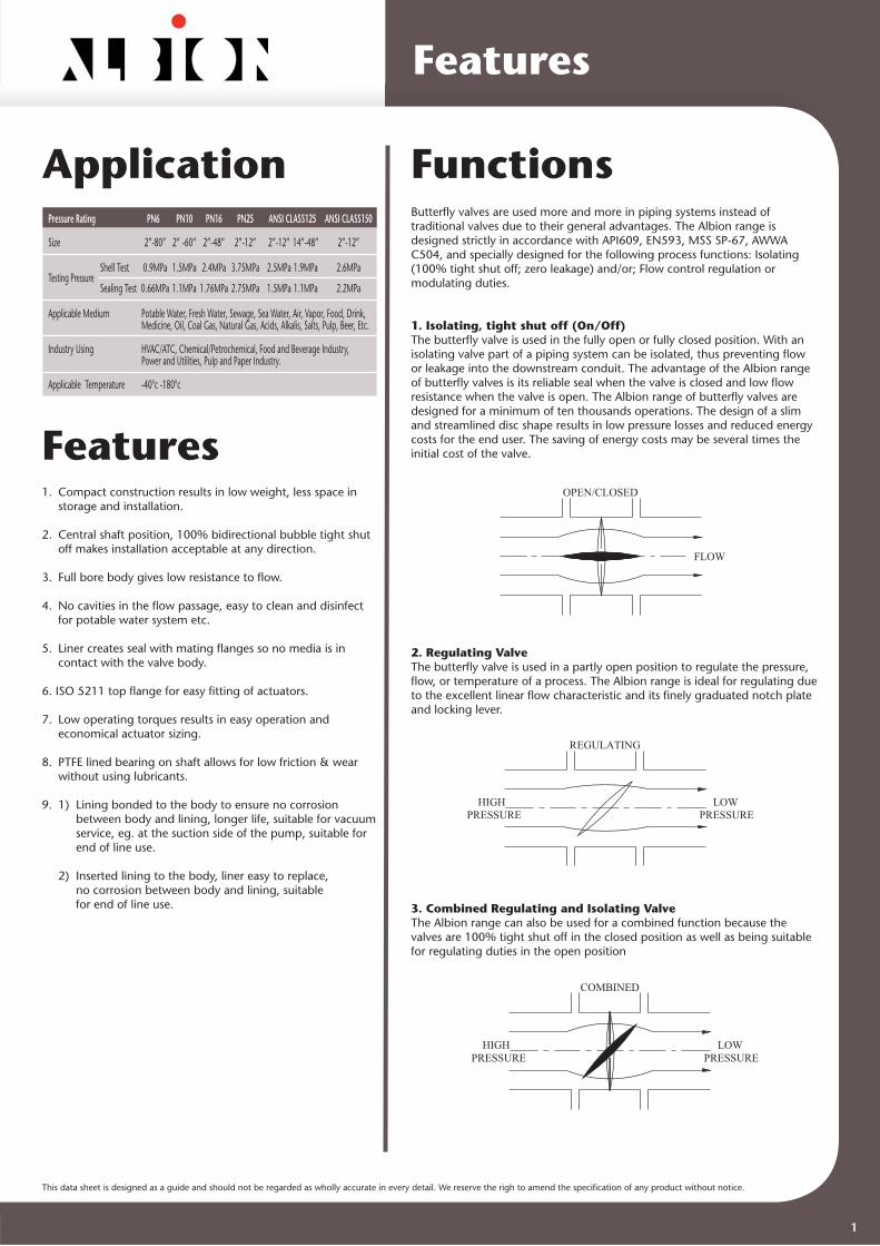
1. Isolating, tight shut off (On/Off) The butterfl y valve is used in the fully open or fully closed position. With an isolating valve part of a piping system can be isolated, thus preventing fl ow or leakage into the downstream conduit. The advantage of the Albion range of butterfl y valves is its reliable seal when the valve is closed and low fl ow resistance when the valve is open. The Albion range of butterfl y valves are designed for a minimum of ten thousands operations. The design of a slim and streamlined disc shape results in low pressure losses and reduced energy costs for the end user. The saving of energy costs may be several times the initial cost of the valve.
2. Regulating Valve The butterfl y valve is used in a partly open position to regulate the pressure, fl ow, or temperature of a process. The Albion range is ideal for regulating due to the excellent linear fl ow characteristic and its fi nely graduated notch plate and locking lever.
3. Combined Regulating and Isolating Valve The Albion range can also be used for a combined function because thevalves are 100% tight shut off in the closed position as well as being suitablefor regulating duties in the open position
FLOW
OPEN/CLOSED
HIGHPRESSURE
LOWPRESSURE
REGULATING
HIGHPRESSURE
LOWPRESSURE
COMBINED
1

This data sheet is designed as a guide and should not be regarded as wholly accurate in every detail. We reserve the righ to amend the specifi cation of any product without notice.
Dimensions
Face to Face Mating FlangeInternational Flange Standard
Flange
Butterfl y valves are designed with face to face dimensions according to international standard.
Wafer valve types PN6/10/16/25 Double fl anged valves Basic series 20 Basic series 13 ISO ASME ISO EN 5752/20 GB API609 B16.10. EN 5752/13 GB API609 558-1/20 DIN 3202 12221-89 tab.8 558-1/13 DIN 3202, 12221-89 DN NPS K1 col.3/4 F16
40 1 1/2 33 33 33 - 33 106 106 106 -
50 2 43 43 43 43 43 108 108 108 -
65 2 1/2 46 46 46 46 46 112 112 112 -
80 3 46 46 46 46 46 114 114 114 114
100 4 52 52 52 52 52 127 127 127 127
125 5 56 56 56 56 56 140 140 140 -
150 6 56 56 56 56 56 140 140 140 140
175 7 - - - - - - 140 - -
200 8 60 60 60 60 60 152 152 152 152
250 10 68 68 68 68 68 165 165 165 165
300 12 78 78 78 78 78 178 178 178 178
350 14 78 78 78 78 78 190 190 190 190
400 16 102 102 102 102 79 216 216 216 216
450 18 114 114 114 114 102 222 222 222 222
500 20 127 127 127 127 111 229 229 229 229
600 24 154 154 154 154 154 267 267 267 267
700 28 165 165 165 - - 292 292 292 -
750 30 - - - 165 165 - - - -
800 32 190 190 190 - - 318 318 318 -
900 36 203 203 203 200 200 330 330 330 -
1000 40 216 216 216 - - 410 410 410 -
1050 42 - - - 251 251 - - - -
1100 44 - - - - - - - - -
1200 48 254 254 254 276 276 470 470 470 -
1400 56 279 - 279 - - 530 530 530 -
1600 64 318 - 318 - - 600 600 600 -
1800 72 356 - 356 - - 670 670 670 -
2000 80 406 - 406 - - 760 760 760 -
EN ANSI GB JIS BS
PN6 1092-1, 1092-2 9113 4504
PN10 1092-1, 1092-2 9113 4504
PN16 1092-1, 1092-2 9113 4504
Class 125 B16.1
Class 150 B16.5, B16.47
JIS 5K B 2211
JIS 10K B 2212
JS 16K B 2213
Size EN1092-1 PN6 EN1092-1 PN10 EN1092-1 PN16
DN NPS OD PCD Bolt OD PCD Bolt OD PCD Bolt
40 1 1/2 130 100 4XM12 150 110 4XM16 150 110 4XM16
50 2 140 110 4XM12 165 125 4XM16 165 125 4XM16
65 2 1/2 160 130 4XM12 185 145 4XM16 185 145 4XM16
80 3 190 150 4XM16 200 160 8XM16 200 160 8XM16
100 4 210 170 4XM16 220 180 8XM16 220 180 8XM16
125 5 240 200 8XM16 250 210 8XM16 250 210 8XM16
150 6 265 225 8XM16 285 240 8XM20 285 240 8XM20
200 8 320 280 8XM16 340 295 8XM20 340 295 12XM20
250 10 375 335 12XM16 395 350 12XM20 405 355 12XM24
300 12 440 395 12XM20 445 400 12XM20 460 410 12XM24
350 14 490 445 12XM20 505 460 16XM20 520 470 16XM24
400 16 540 495 16XM20 565 515 16XM24 580 525 16XM27
450 18 595 550 16XM20 615 565 20XM24 640 585 20XM27
500 20 645 600 20XM20 670 620 20XM24 715 650 20XM30
600 24 755 705 20XM24 780 725 20XM27 840 770 20XM33
700 28 860 810 24XM24 895 840 24XM27 910 840 24XM33
800 32 975 920 24XM27 1015 950 24XM30 1025 950 24XM36
900 36 1075 1020 24XM27 1115 1050 28XM30 1125 1050 28XM36
1000 40 1175 1120 28XM27 1230 1160 28XM33 1255 1170 28XM39
1100 44 - - - 1340 1270 32XM33 1355 1270 32XM39
1200 48 1405 1340 32XM30 1455 1380 32XM36 1485 1390 32XM45
1400 56 1630 1560 36XM33 1675 1590 36XM39 1685 1590 36XM45
1500 60 - - - 1785 1700 36XM39 1820 1710 36XM52
1600 64 1830 1760 40XM33 1915 1820 40XM45 1930 1820 40XM52
1800 72 2045 1970 44XM36 2115 2020 44XM45 2130 2020 44XM52
2000 80 2265 2180 48XM39 2325 2230 48XM45 2345 2230 48XM56
2
This data sheet is designed as a guide and should not be regarded as wholly accurate in every detail. We reserve the righ to amend the specifi cation of any product without notice.
Dimensions
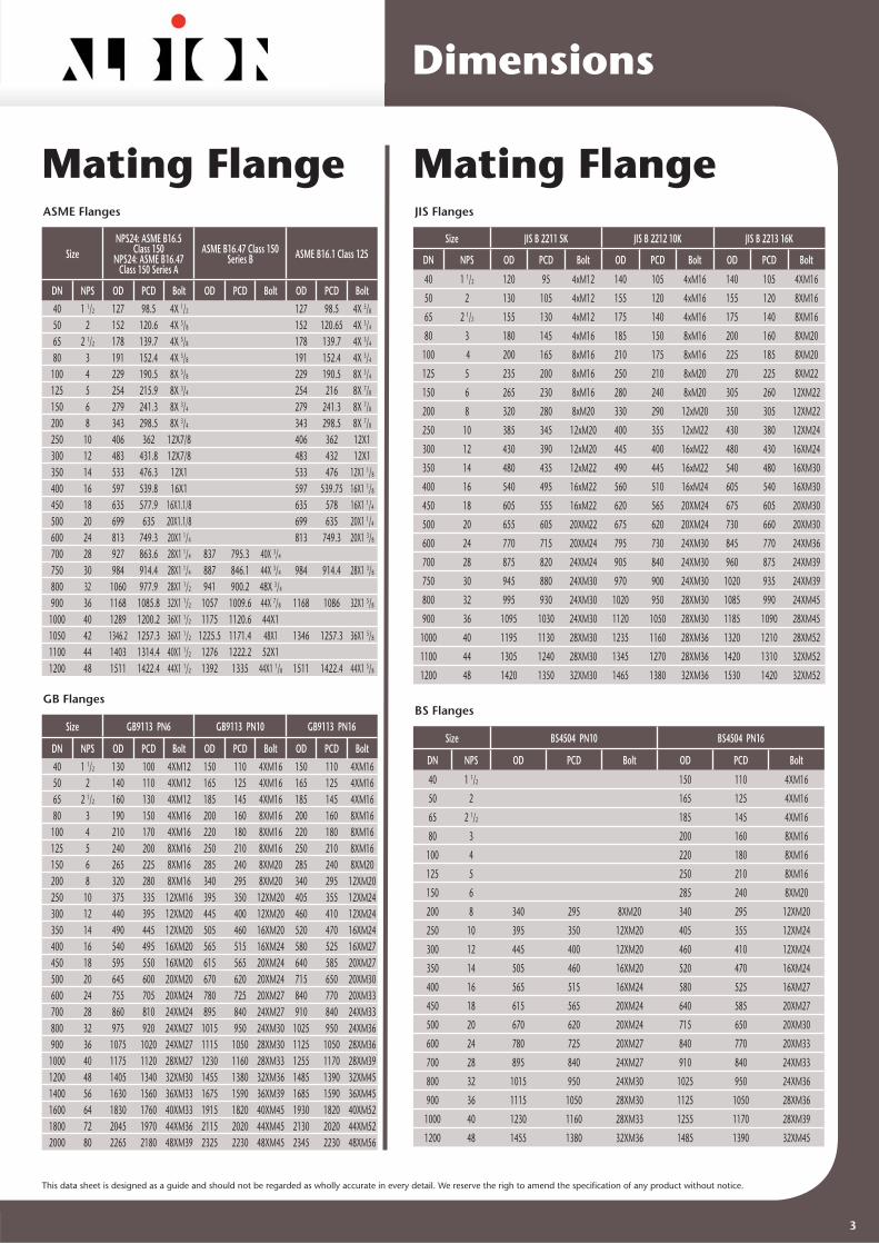
Mating FlangeASME Flanges
GB Flanges
SizeNPS24: ASME B16.5
Class 150NPS24: ASME B16.47
Class 150 Series A
ASME B16.47 Class 150 Series B ASME B16.1 Class 125
DN NPS OD PCD Bolt OD PCD Bolt OD PCD Bolt
40 1 1/2 127 98.5 4X 1/2 127 98.5 4X 5/8
50 2 152 120.6 4X 5/8 152 120.65 4X 3/4
65 2 1/2 178 139.7 4X 5/8 178 139.7 4X 3/4
80 3 191 152.4 4X 5/8 191 152.4 4X 3/4
100 4 229 190.5 8X 5/8 229 190.5 8X 3/4
125 5 254 215.9 8X 3/4 254 216 8X 7/8
150 6 279 241.3 8X 3/4 279 241.3 8X 7/8
200 8 343 298.5 8X 3/4 343 298.5 8X 7/8
250 10 406 362 12X7/8 406 362 12X1300 12 483 431.8 12X7/8 483 432 12X1350 14 533 476.3 12X1 533 476 12X1 1/8
400 16 597 539.8 16X1 597 539.75 16X1 1/8
450 18 635 577.9 16X1.1/8 635 578 16X1 1/4
500 20 699 635 20X1.1/8 699 635 20X1 1/4
600 24 813 749.3 20X1 1/4 813 749.3 20X1 3/8
700 28 927 863.6 28X1 1/4 837 795.3 40X 3/4
750 30 984 914.4 28X1 1/4 887 846.1 44X 3/4 984 914.4 28X1 3/8
800 32 1060 977.9 28X1 1/2 941 900.2 48X 3/4
900 36 1168 1085.8 32X1 1/2 1057 1009.6 44X 7/8 1168 1086 32X1 5/8
1000 40 1289 1200.2 36X1 1/2 1175 1120.6 44X11050 42 1346.2 1257.3 36X1 1/2 1225.5 1171.4 48X1 1346 1257.3 36X1 5/8
1100 44 1403 1314.4 40X1 1/2 1276 1222.2 52X11200 48 1511 1422.4 44X1 1/2 1392 1335 44X1 1/8 1511 1422.4 44X1 5/8
Mating FlangeJIS Flanges
BS Flanges
Size JIS B 2211 5K JIS B 2212 10K JIS B 2213 16K
DN NPS OD PCD Bolt OD PCD Bolt OD PCD Bolt
40 1 1/2 120 95 4xM12 140 105 4xM16 140 105 4XM16
50 2 130 105 4xM12 155 120 4xM16 155 120 8XM16
65 2 1/2 155 130 4xM12 175 140 4xM16 175 140 8XM16
80 3 180 145 4xM16 185 150 8xM16 200 160 8XM20
100 4 200 165 8xM16 210 175 8xM16 225 185 8XM20
125 5 235 200 8xM16 250 210 8xM20 270 225 8XM22
150 6 265 230 8xM16 280 240 8xM20 305 260 12XM22
200 8 320 280 8xM20 330 290 12xM20 350 305 12XM22
250 10 385 345 12xM20 400 355 12xM22 430 380 12XM24
300 12 430 390 12xM20 445 400 16xM22 480 430 16XM24
350 14 480 435 12xM22 490 445 16xM22 540 480 16XM30
400 16 540 495 16xM22 560 510 16xM24 605 540 16XM30
450 18 605 555 16xM22 620 565 20XM24 675 605 20XM30
500 20 655 605 20XM22 675 620 20XM24 730 660 20XM30
600 24 770 715 20XM24 795 730 24XM30 845 770 24XM36
700 28 875 820 24XM24 905 840 24XM30 960 875 24XM39
750 30 945 880 24XM30 970 900 24XM30 1020 935 24XM39
800 32 995 930 24XM30 1020 950 28XM30 1085 990 24XM45
900 36 1095 1030 24XM30 1120 1050 28XM30 1185 1090 28XM45
1000 40 1195 1130 28XM30 1235 1160 28XM36 1320 1210 28XM52
1100 44 1305 1240 28XM30 1345 1270 28XM36 1420 1310 32XM52
1200 48 1420 1350 32XM30 1465 1380 32XM36 1530 1420 32XM52
Size BS4504 PN10 BS4504 PN16
DN NPS OD PCD Bolt OD PCD Bolt
40 1 1/2 150 110 4XM16
50 2 165 125 4XM16
65 2 1/2 185 145 4XM16
80 3 200 160 8XM16
100 4 220 180 8XM16
125 5 250 210 8XM16
150 6 285 240 8XM20
200 8 340 295 8XM20 340 295 12XM20
250 10 395 350 12XM20 405 355 12XM24
300 12 445 400 12XM20 460 410 12XM24
350 14 505 460 16XM20 520 470 16XM24
400 16 565 515 16XM24 580 525 16XM27
450 18 615 565 20XM24 640 585 20XM27
500 20 670 620 20XM24 715 650 20XM30
600 24 780 725 20XM27 840 770 20XM33
700 28 895 840 24XM27 910 840 24XM33
800 32 1015 950 24XM30 1025 950 24XM36
900 36 1115 1050 28XM30 1125 1050 28XM36
1000 40 1230 1160 28XM33 1255 1170 28XM39
1200 48 1455 1380 32XM36 1485 1390 32XM45
Size GB9113 PN6 GB9113 PN10 GB9113 PN16
DN NPS OD PCD Bolt OD PCD Bolt OD PCD Bolt
40 1 1/2 130 100 4XM12 150 110 4XM16 150 110 4XM1650 2 140 110 4XM12 165 125 4XM16 165 125 4XM1665 2 1/2 160 130 4XM12 185 145 4XM16 185 145 4XM1680 3 190 150 4XM16 200 160 8XM16 200 160 8XM16
100 4 210 170 4XM16 220 180 8XM16 220 180 8XM16125 5 240 200 8XM16 250 210 8XM16 250 210 8XM16150 6 265 225 8XM16 285 240 8XM20 285 240 8XM20200 8 320 280 8XM16 340 295 8XM20 340 295 12XM20250 10 375 335 12XM16 395 350 12XM20 405 355 12XM24300 12 440 395 12XM20 445 400 12XM20 460 410 12XM24350 14 490 445 12XM20 505 460 16XM20 520 470 16XM24400 16 540 495 16XM20 565 515 16XM24 580 525 16XM27450 18 595 550 16XM20 615 565 20XM24 640 585 20XM27500 20 645 600 20XM20 670 620 20XM24 715 650 20XM30600 24 755 705 20XM24 780 725 20XM27 840 770 20XM33700 28 860 810 24XM24 895 840 24XM27 910 840 24XM33800 32 975 920 24XM27 1015 950 24XM30 1025 950 24XM36900 36 1075 1020 24XM27 1115 1050 28XM30 1125 1050 28XM36
1000 40 1175 1120 28XM27 1230 1160 28XM33 1255 1170 28XM391200 48 1405 1340 32XM30 1455 1380 32XM36 1485 1390 32XM451400 56 1630 1560 36XM33 1675 1590 36XM39 1685 1590 36XM451600 64 1830 1760 40XM33 1915 1820 40XM45 1930 1820 40XM521800 72 2045 1970 44XM36 2115 2020 44XM45 2130 2020 44XM522000 80 2265 2180 48XM39 2325 2230 48XM45 2345 2230 48XM56
3

This data sheet is designed as a guide and should not be regarded as wholly accurate in every detail. We reserve the righ to amend the specifi cation of any product without notice.
SizePN10 PN16
Stud Bolt Hexagon Head Bolt Stud Bolt Hexagon
Head Bolt
DN NPS Qty Dia Length Qty Dia x L Qty Dia Length Qty Dia x L
50 2 4 M16 130 4X2 M16X40 4 M16 130 4X2 M16X40
65 2 1/2 4 M16 140 4X2 M16X45 4 M16 140 4X2 M16X45
80 3 8 M16 140 8X2 M16X45 8 M16 140 8X2 M16X45
100 4 8 M16 150 8X2 M16X50 8 M16 150 8X2 M16X50
125 5 8 M16 150 8X2 M16X50 8 M16 150 8X2 M16X50
150 6 8 M20 165 8X2 M20X50 8 M20 165 8X2 M20X50
200 8 8 M20 175 8X2 M20X55 12 M20 175 12X2 M20X55
250 10 12 M20 185 12X2 M20X60 12 M24 185 12X2 M24X60
300 12 12 M20 195 12X2 M20X65 12 M24 200 12X2 M24X65
350 14 16 M20 195 16X2 M20X65 16 M24 200 16X2 M24X65
400 16 16 M24 220 16X2 M24X75 16 M27 230 16X2 M27X75
450 18 20 M24 250 20X2 M24X80 20 M27 254 20X2 M27X80
500 20 20 M24 290 20X2 M24X90 20 M30 294 20X2 M30X99
600 24 20 M27 324 20X2 M27X100 20 M33 334 20X2 M33X100
700 28 24 M27 334 24X2 M27X100 24 M33 341 24X2 M33X100
800 32 24 M30 364 24X2 M30X100 24 M36 375 24X2 M36X100
900 36 28 M30 388
1000 40 28 M33 411
Installation
Wafer Butterfl yValveSize & Quantity of Bolts
SizeANSI 125/150, MSS-SP44
Stud Bolt Hexagon Head Bolt
DN NPS Qty Dia Length Qty UNCXL
50 2 4 5/8" 120 4X2 5/8"X35
65 2 1/2 4 5/8" 130 4X2 5/8"X40
80 3 4 5/8" 133 4X2 5/8"X40
100 4 8 5/8" 139 8X2 5/8"X45
125 5 8 3/4" 152 8X2 3/4"X45
150 6 8 3/4" 155 8X2 3/4"X45
200 8 8 3/4" 165 8X2 3/4"X50
250 10 12 7/8" 183 12X2 7/8"X60
300 12 12 7/8" 196 12X2 7/8"X65
350 14 12 1" 214 12X2 1"X70
400 16 16 1" 241 16X2 1"X85
450 18 16 1 1/8" 265 16X2 1 1/8"X90
500 20 20 1 1/8" 284 20X2 1 1/8"X100
600 24 20 1 1/4" 305 20X2 1 1/4"X110
700 28 28 1 1/4" 350 28X2 1 1/4"X110
750 30 28 1 1/4" 355 28X2 1 1/4"X110
800 32 28 1 1/2" 410 28X2 1 1/2"X110
900 36 32 1 1/2" 450
1000 40 36 1 1/2" 490
Installation Type
Installation forDifferent Body Types
Albion butterfl y valves are designed for installation between fl anges. They areeasily installed or removed from the pipeline system. It is important the correct body style is selected for the designed installation requirements.
Body types
Valveinstallation requirements
Full wafer short type
Semi-lug wafer short
type
Lugged wafer short
type
Single fl anged
wafer short type
Double fl anged
wafer short type
Double fl anged
type
Clamping between fl anges OK OK OK OK
Installation between fl anges and possibility for downstream pipe dismantling
OK OK OK OK
Valve bolted at end of the line fl ange OK OK OK OK
Bolting directly to hull OK OK
Suitable for insulation of pipes OK OK OK OK OK OK
Full wafer short type
STUD BOLT
Semi-lug wafer short type
STUD BOLT
Single flanged wafer short type
STUD BOLT
Double flanged type
STUD BOLT
Double flanged wafer short type
STUD BOLT
Lugged wafer short type
HEXAGON HEAD BOLT
4
This data sheet is designed as a guide and should not be regarded as wholly accurate in every detail. We reserve the righ to amend the specifi cation of any product without notice.
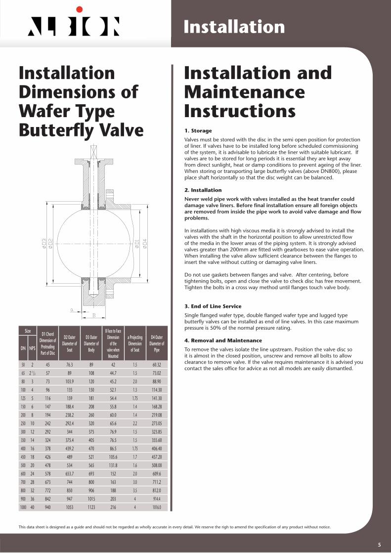
Size D1 Chord Dimension of
Protruding Part of Disc
D2 Outer Diameter of
Seat
D3 Outer Diameter of
Body
B Face to Face Dimension
of the valve when Mounted
a Projecting Dimension
of Seat
D4 Outer Diameter of
PipeDN NPS
50 2 45 76.3 89 42 1.5 60.32
65 2 1/2 57 89 108 44.7 1.5 73.02
80 3 73 103.9 120 45.2 2.0 88.90
100 4 96 135 150 52.1 1.3 114.30
125 5 116 159 181 54.4 1.75 141.30
150 6 147 188.4 208 55.8 1.4 168.28
200 8 194 238.2 260 60.0 1.4 219.08
250 10 242 292.4 320 65.6 2.2 273.05
300 12 292 344 375 76.9 1.5 323.85
350 14 324 375.4 405 76.5 1.5 355.60
400 16 378 439.2 470 86.5 1.75 406.40
450 18 426 489 521 105.6 1.7 457.20
500 20 478 534 565 131.8 1.6 508.00
600 24 578 653.7 693 152 2.0 609.6
700 28 673 744 800 163 3.0 711.2
800 32 772 850 906 188 3.5 812.0
900 36 842 947 1015 203 4 914.4
1000 40 940 1053 1123 216 4 1016.0
Installation
InstallationDimensions ofWafer Type Butterfl y Valve
Installation and MaintenanceInstructions1. Storage
Valves must be stored with the disc in the semi open position for protection of liner. If valves have to be installed long before scheduled commissioning of the system, it is advisable to lubricate the liner with suitable lubricant. If valves are to be stored for long periods it is essential they are kept away from direct sunlight, heat or damp conditions to prevent ageing of the liner. When storing or transporting large butterfl y valves (above DN800), please place shaft horizontally so that the disc weight can be balanced.
2. Installation
Never weld pipe work with valves installed as the heat transfer could damage valve liners. Before fi nal installation ensure all foreign objects are removed from inside the pipe work to avoid valve damage and fl ow problems.
In installations with high viscous media it is strongly advised to install the valves with the shaft in the horizontal position to allow unrestricted fl ow of the media in the lower areas of the piping system. It is strongly advised valves greater than 200mm are fi tted with gearboxes to ease valve operation.When installing the valve allow suffi cient clearance between the fl anges to insert the valve without cutting or damaging valve liners.
Do not use gaskets between fl anges and valve. After centering, before tightening bolts, open and close the valve to check disc has free movement.Tighten the bolts in a cross way method until fl anges touch valve body.
3. End of Line Service
Single fl anged wafer type, double fl anged wafer type and lugged type butterfl y valves can be installed as end of line valves. In this case maximum pressure is 50% of the normal pressure rating.
4. Removal and Maintenance
To remove the valves isolate the line upstream. Position the valve disc so it is almost in the closed position, unscrew and remove all bolts to allow clearance to remove valve. If the valve requires maintenance it is advised you contact the sales offi ce for advice as not all models are easily dismantled.
5

This data sheet is designed as a guide and should not be regarded as wholly accurate in every detail. We reserve the righ to amend the specifi cation of any product without notice.
Size Standard disc, maximum differential pressure
DN NPS 6bar 10bar 200LBF/IN2 13bar 285LBF/
IN2 25bar
50 2 14 14 15 15 15 15
65 2 1/2 14 14 17 17 20 20
80 3 19 19 22 22 40 40
100 4 33 33 34 34 50 50
125 5 46 46 48 48 70 70
150 6 72 72 73 73 95 95
200 8 145 145 155 155 220 220
250 10 230 230 236 236 320 320
300 12 320 320 330 330 421 421
350 14 560 570 720 790
400 16 770 850 1000 1180
450 18 1210 1220 1380 1520
500 20 1420 1430 1780 1930
600 24 2820 2830 3530 3670
700 28 4860 4970
750 30 5230 5280
800 32 6500 6600
900 36 7620 8010
1000 40 8540 10810
1100 44 9760 15110
1200 48 13700 21200
Technical
Valve Seating Torques
Valve Flow RateKV-Values-Valve Rated Flow Coeffi cients (M3/H At 1 Bar ΔP)
90°=fully open. Flow in gallons/min at 1 lbs/in2 pressure drop, multiply Kv by 0.963 for UK gpm, or multiply Kv by 1.156 for US gpm.
All torque values shown on chart are for “wet” (water and other non-lubricating media) on-off service. For “dry” service (non-lubricating, dry gas media), multiply values by 1.15. For “lubed” service (clean, non-abrasive media) multiply values by 0.85. When sizing actuators for single valve applications, multiply the above torques by 1.25. Under certain conditions, hydrodynamic torque can meet or exceed seating and unseating torques. When designing valve systems hydrodynamic torques multiply above torques by 0.85.
Size Opening Angle
DN NPS 10° 20° 30° 40° 50° 60° 70° 80° 90°
50 2 0.9 6.3 14 29 53 94 116 118
65 2 1/2 2.5 11 28 50 92 168 245 258
80 3 5.3 22 50 90 157 282 460 510
100 4 9.8 40 90 158 268 485 823 926
125 5 16 70 150 263 430 766 1350 1500
150 6 84 113 230 395 640 1096 1850 2170
200 8 112 212 405 678 1084 1785 3045 3842
250 10 20 155 309 590 989 1590 2716 4765 5014
300 12 48 283 384 745 1253 2058 3742 6820 9230
350 14 125 314 660 1185 2005 3222 5196 9300 10790
400 16 162 413 863 1545 2622 4200 6772 12140 14081
450 18 198 512 1070 1915 3249 5216 8416 15150 17842
500 20 248 630 1325 2365 4015 6440 10400 18624 22030
600 24 356 905 1899 3408 5778 9273 14985 26758 31780
700 28 485 1236 2580 4640 7862 12628 20358 36482 43200
750 30 556 1586 3420 7280 12300 18624 29372 40050 49780
800 32 630 2012 5080 9700 15000 22205 34508 47580 55000
900 36
1000 40
1100 44
1200 48 Torque in Nm
6

This data sheet is designed as a guide and should not be regarded as wholly accurate in every detail. We reserve the righ to amend the specifi cation of any product without notice.
Type of material Material standard Example for application
Cast ironHT250,EN1561:GJL250 GG25, DIN 1691 Class B, ASTM A126
Grade 250, BS 2789
General application,not suitable for pressure shocks or rapid
closing valves.
Ductile iron
QT400,EN1563:GJS400-15/18; GJS500-7 GGG40, DIN 1693
60-40-18,ASTM A536 400-18, BS 2789
General application
Ductile iron(Heat treated) GGG40.3 DIN 1693 EN1563:GJS400-18
Heavy applications, Cold applications, petrochemical industries, power stations, alternative for cast steel
Cast carbon steel GS-C 25, DIN 17245 WCB, ASTM A216 161-430A,BS 1504
Heavy applications,petrochemical industries.
Cast stainless steel CF8, ASTM A351 CF8M,ASTM A351 Medicine, food, drink
BronzeC-CuSn10Zn, DIN 1705(RG
10) C90500, ASTM B584 LG1, BS 1400
Marine service
Type of material Material standard Temperature range Example for application
Nitrile rubber NBR 0°C - 90°CAliphatic hydrocarbons(fuels, low
aromatic containing oils, gases), sea water, compressed air, powders, granular, gas supply
Ethylene-propylene rubber EPDM -20°C - 110°C
Water in general (hot-, cold-, sea-, ozone-, swimming-, industrial-, etc). Weak acids,
weak salt solutions, alcohols, ketones, sourgases, sugar juice
Specialethylene-propylene rubber Special EPDM -10°C - 70°C Potable water, foodstuffs,
unchlorined drinking water
Specialethylene-propylene rubber Special EPDM -30°C - 120°C HVAC, chilled water, food stuffs & sugar juice
Viton Viton 0°C - 200°CMany aliphatic, aromatic and halogen hydrocarbons, hot gases, hot water,
steam, inorganic acid, alkali
Special viton Special viton 0°C - 130°C Concentrated acids
PTFE PTFE 10°C - 155°C Fit for acids, alkalis, oil, not fi t for low temperature
Materials
Body Materials Body Lining Materials
Type of material Material standard In combination with disc material
Carbon steel zinc plated ASTM A105 Ductile iron, non corrosive hot or cold water, economical valve
Stainless steel SS410 Stainless steel, ductile iron
High strength stainless steel 1Cr17Ni2 ASTM A431 Stainless steel, ductile iron
Stainless steel SS316 Stainless steel, ductile iron, aluminum bronze
Aluminum bronze CuA10Ni5Fe4, DIN 17665 C63000, ASTM B150 Aluminum bronze
Monel NA18, BS 3076 Aluminum bronze(high pressure application)
Hastelloy C276 ASTM B574, N10276 Hastelloy
Shaft MaterialsMaterials for shafts are selected on the basic of disc materials
NOTE: For use in fl uids containing ammonia, all valve parts should be made from materials with no copper content.
It is essential for each individual case, that the selection of the type of rubber complies with medium characteristics. As the body is internally fully rubber lined, the body material is
protected from corrosion by the medium.
Type of material Material standard Example for application
Ductile iron nickel platedQT400,EN1563:GJS400-15/18 GGG40, DIN 1693 60-40-18, ASTM A536 400-18, BS 2789
Air, non corrosive hot or cold water
Ductile iron,340µm nylon coated
QT400,EN1563:GJS400-15/18 GGG40, DIN 1693 60-40-18, ASTM A536 400-18, BS 2789
(PH 4.5-9,70°C) Potable water, water(max. 70°C, PH value
between 4.5 and 9)
Ductile iron, PTFE coatedQT400,EN1563:GJS400-15/18 GGG40, DIN 1693 60-40-18, ASTM A536 400-18, BS 2789
Acids, alkalis, oil, water, air
Cast stainless steel CF8M, ASTM A351
Potable water, demineralized water, solvents, industrial water,
not recommended for sea water, gas
Duplex stainless steel 1.4408, 1.4462, 1.4581, EN 10088 A181, Grade F51 SAF 2507
Potable water, cooling water, sea water, demineralized water,
solvents, foodstuff
Aluminum bronze G-CuAl10Ni, DIN 1714 C95400, ASTM B148 AB2, BS 1400 Sea water, potable water, gas
HastelloyA494, CW-12MW, Hastelloy-C22,
Hastelloy-C276, Hastelloy-C-4, Hastelloy-F, Hastelloy-N
Phosphoric, hypochloric, acetic, formic, sulfurous
Disc MaterialsAs the disc is in contact with medium, the material should be carefully selected.
7

This data sheet is designed as a guide and should not be regarded as wholly accurate in every detail. We reserve the righ to amend the specifi cation of any product without notice.
Valve Operation
Level OperatorsGear OperatorsAlbion butterfl y valves can be supplied for operation by lever,
gearbox or actuator. Bare shaft valves can also be supplied.
Levers are available for sizes DN50 to DN300 (2” to 12”), but it is recommended that gear operators be used on sizes DN200 (8”) and larger size.
The gear box is available for all sizes from DN50 to DN2000 (2”to 80”).
The gear box housing from DN50 to DN300 (2” to 12”)is die-cast aluminum. This is aesthetically pleasing and offers a very light weight construction.
It is fi tted with an accurate position indicator which is lockable making the gearbox extremely good for controlling and setting memory stops.
The housing for DN350 (14”) and above size is cast iron.
For all gear boxes the drive stem and worm stem is made fromCarbon steel and the worm gear is ductile iron.
LEVER+PADLOCK FACILITY
LEVER FOR REGULATING
STANDARD LEVER
TUHS
OPEN Indicator Scale
Indicator Pointer
8
This data sheet is designed as a guide and should not be regarded as wholly accurate in every detail. We reserve the righ to amend the specifi cation of any product without notice.
Valve Operation
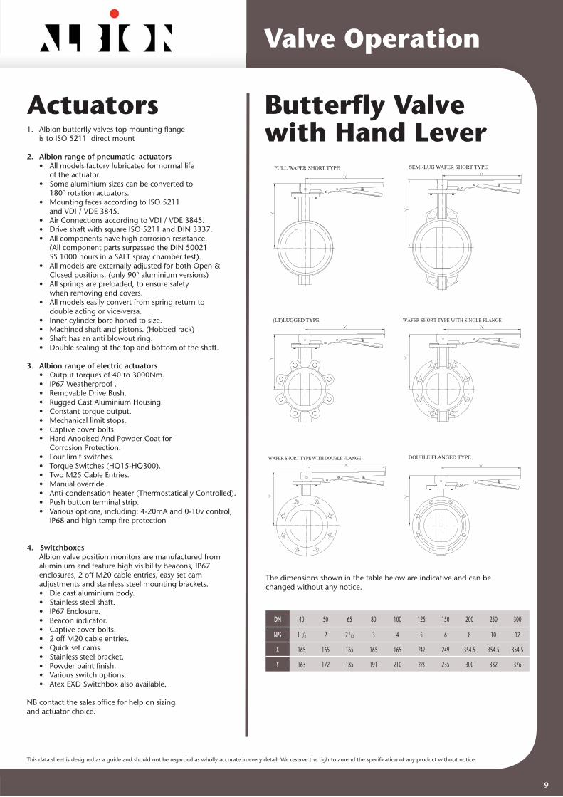
Butterfl y Valvewith Hand Lever
FULL WAFER SHORT TYPE SEMI-LUG WAFER SHORT TYPE
(LT)LUGGED TYPE
DOUBLE FLANGED TYPE
WAFER SHORT TYPE WITH SINGLE FLANGE
WAFER SHORT TYPE WITH DOUBLE FLANGE
The dimensions shown in the table below are indicative and can be changed without any notice.
DN 40 50 65 80 100 125 150 200 250 300
NPS 1 1/2 2 2 1/2 3 4 5 6 8 10 12
X 165 165 165 165 165 249 249 354.5 354.5 354.5
Y 163 172 185 191 210 223 235 300 332 376
9
Actuators1. Albion butterfl y valves top mounting fl ange is to ISO 5211 direct mount
2. Albion range of pneumatic actuators • All models factory lubricated for normal life of the actuator. • Some aluminium sizes can be converted to 180° rotation actuators. • Mounting faces according to ISO 5211 and VDI / VDE 3845. • Air Connections according to VDI / VDE 3845. • Drive shaft with square ISO 5211 and DIN 3337. • All components have high corrosion resistance. (All component parts surpassed the DIN 50021 SS 1000 hours in a SALT spray chamber test). • All models are externally adjusted for both Open & Closed positions. (only 90° aluminium versions) • All springs are preloaded, to ensure safety when removing end covers. • All models easily convert from spring return to double acting or vice-versa. • Inner cylinder bore honed to size. • Machined shaft and pistons. (Hobbed rack) • Shaft has an anti blowout ring. • Double sealing at the top and bottom of the shaft.
3. Albion range of electric actuators • Output torques of 40 to 3000Nm. • IP67 Weatherproof . • Removable Drive Bush. • Rugged Cast Aluminium Housing. • Constant torque output. • Mechanical limit stops. • Captive cover bolts. • Hard Anodised And Powder Coat for Corrosion Protection. • Four limit switches. • Torque Switches (HQ15-HQ300). • Two M25 Cable Entries. • Manual override. • Anti-condensation heater (Thermostatically Controlled). • Push button terminal strip. • Various options, including: 4-20mA and 0-10v control, IP68 and high temp fi re protection
4. Switchboxes Albion valve position monitors are manufactured from aluminium and feature high visibility beacons, IP67 enclosures, 2 off M20 cable entries, easy set cam adjustments and stainless steel mounting brackets. • Die cast aluminium body. • Stainless steel shaft. • IP67 Enclosure. • Beacon indicator. • Captive cover bolts. • 2 off M20 cable entries. • Quick set cams. • Stainless steel bracket. • Powder paint fi nish. • Various switch options. • Atex EXD Switchbox also available.
NB contact the sales offi ce for help on sizingand actuator choice.

This data sheet is designed as a guide and should not be regarded as wholly accurate in every detail. We reserve the righ to amend the specifi cation of any product without notice.
Butterfl y Valvewith Gearbox
FULL WAFER SHORT TYPE SEMI-LUG WAFER SHORT TYPE
(LT)LUGGED TYPE
DOUBLE FLANGED TYPE
WAFER SHORT TYPE WITH SINGLE FLANGE
WAFER SHORT TYPE WITH DOUBLE FLANGE
The dimensions shown in the table below are indicative and can be changed without any notice.
DN 40 50 65 80 100 125 150 200 250 300
NPS 1.1/2 2 2.1/2 3 4 5 6 8 10 12
X 140 140 140 140 140 140 140 222 222 222
X1 45 45 45 45 45 45 45 76 76 76
Y 161 170 183 189 208 221 233 284 316 360
D 133 133 133 133 133 133 133 215 215 215
Butterfl y Valvewith Gearbox
The dimensions shown in the table below are indicative and can be changed without any notice.
DN 400 450 500 600 700 750 800 900 1000 1200 1400 1600 1800 2000
NPS 16 18 20 24 28 30 32 36 40 48 56 64 72 80
D 300 300 300 386 386 386 386 386 386 386
X 186 186 186 243 243 243 243 278 278 320
X1 270 270 270 350 350 350 350 450 450 490
Y 466 488 546 640 702 738 750 855 935 1076
Y1 66 66 66 95 95 95 95 126 126 126
SEMI-LUG WAFER SHORT TYPE (LT )LUGGED TYPE
DOUBLE FLANGED TYPE
WAFER SHORT TYPE WITH SINGLE FLANGE WAFER SHORT TYPE WITH DOUBLE FLANGE
Valve Operation
10
This data sheet is designed as a guide and should not be regarded as wholly accurate in every detail. We reserve the righ to amend the specifi cation of any product without notice.
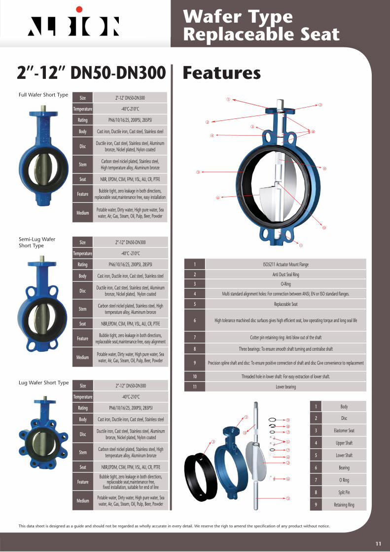
Wafer TypeReplaceable Seat
2”-12” DN50-DN300Full Wafer Short Type Size 2"-12" DN50-DN300
Temperature -40°C-210°C
Rating PN6/10/16/25, 200PSI, 285PSI
Body Cast iron, Ductile iron, Cast steel, Stainless steel
Disc Ductile iron, Cast steel, Stainless steel, Aluminum bronze, Nickel plated, Nylon coated
Stem Carbon steel nickel plated, Stainless steel,High temperature alloy, Aluminum bronze
Seat NBR, EPDM, CSM, FPM, VSL, AU, CR, PTFE
Feature Bubble tight, zero leakage in both directions, replaceable seat,maintenance free, easy installation
Medium Potable water, Dirty water, High pure water, Sea water, Air, Gas, Steam, Oil, Pulp, Beer, Powder
Size 2”-12” DN50-DN300
Temperature -40°C -210°C
Rating PN6/10/16/25, 200PSI, 285PSI
Body Cast iron, Ductile iron, Cast steel, Stainless steel
Disc Ductile iron, Cast steel, Stainless steel, Aluminum bronze, Nickel plated, Nylon coated
Stem Carbon steel nickel plated, Stainless steel, High temperature alloy, Aluminum bronze
Seat NBR,EPDM, CSM, FPM, VSL, AU, CR, PTFE
Feature Bubble tight, zero leakage in both directions, replaceable seat,maintenance free, easy alignment
Medium Potable water, Dirty water, High pure water, Sea water, Air, Gas, Steam, Oil, Pulp, Beer, Powder
Semi-Lug WaferShort Type
Lug Wafer Short Type Size 2”-12” DN50-DN300
Temperature -40°C-210°C
Rating PN6/10/16/25, 200PSI, 285PSI
Body Cast iron, Ductile iron, Cast steel, Stainless steel
Disc Ductile iron, Cast steel, Stainless steel, Aluminum bronze, Nickel plated, Nylon coated
Stem Carbon steel nickel plated, Stainless steel, High temperature alloy, Aluminum bronze
Seat NBR,EPDM, CSM, FPM, VSL, AU, CR, PTFE
Feature Bubble tight, zero leakage in both directions,
replaceable seat,maintenance free,fi xed installation, suitable for end of line
Medium Potable water, Dirty water, High pure water, Sea water, Air, Gas, Steam, Oil, Pulp, Beer, Powder
Features1
23
4
5
6
7
8
9
10
11
3
1
2
4
5
6
6
7
6
7
8
9
1 ISO5211 Actuator Mount Flange
2 Anti Dust Seal Ring
3 O-Ring
4 Multi standard alignment holes: For connection between ANSI, EN or ISO standard fl anges.
5 Replaceable Seat
6 High tolerance machined disc surfaces gives high effi cient seat, low operating torque and long seal life
7 Cotter pin retaining ring: Anti blow out of the shaft
8 Three bearings: To ensure smooth shaft turning and centralise shaft
9 Precision spline shaft and disc: To ensure positive connection of shaft and disc Give convenience to replacement
10 Threaded hole in lower shaft: For easy extraction of lower shaft.
11 Lower bearing
1 Body
2 Disc
3 Elastomer Seat
4 Upper Shaft
5 Lower Shaft
6 Bearing
7 O Ring
8 Split Pin
9 Retaining Ring
11

This data sheet is designed as a guide and should not be regarded as wholly accurate in every detail. We reserve the righ to amend the specifi cation of any product without notice.
Parts List
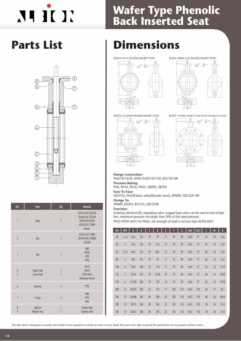
No Parts Qty Material
1 Body 1
ASTM A126 CLASS BDuctile Iron GGG40 ASTM A216 WCBASTM A351 CF8M
Bronze
2 Disc 1 ASTM A351 CF8M
ASTM B148 C95800GGG40
3 Seat 1
NBREPDM
FPM (Viton)PTFE
45
Upper shaftLower shaft
1 1
SS316SS410
ASTM A431Aluminum bronze
6 Bushing 4 PTFE
7 O ring 2 NBRPTFEFPM
89
Split pin Retainer ring
1 1
Carbon steelStainless steel
Wafer TypeReplaceable Seat
DimensionsBODY: FULL WAFER SHORT TYPE
BODY: SEMI-LUG WAFER SHORT TYPE
BODY: LUGGED WAFER SHORT TYPE
DN NPS A B C D E F G nXH ISO5211 L W d
50 2 52.6 142 19 73.5 11 70 90 4X10 F7 43 10 12.6
65 2.1/2 64.4 155 19 80.5 11 70 90 4X10 F7 46 10 12.6
80 3 78.9 161 19 93 11 70 90 4X10 F7 46 10 12.6
100 4 104.1 180 19 110 11 70 90 4X10 F7 52 12 15.77
125 5 123.4 193 19 122.8 14 70 90 4X10 F7 56 14 18.92
150 6 155.96 205 19 139 14 70 90 4X10 F7 56 14 18.92
200 8 202.87 250 25 175 17 102 125 4X12 F10 60 17 22.1
250 10 250.88 282 40 208 22 102 125 4X12 F10 68 22 28.45
300 12 301.9 326 40 244 22 102 125 4X12 F10 78 24 31.6
Flange Connection:PN6/10/16/25, ANSI CLASS125/150, JIS5/10/16KPressure Rating:PN6, PN10, PN16, PN25, 200PSI, 285PSIFace To Face:ISO5752, EN558 basic series 20 (wafer short), API609, GB12221-89Design To:API609, EN593, BS5155, GB12238, BS3952, MSS-SP-67, JIS B2032Function:Isolating valve(on/off), regulating valve Lugged type valve can be used at end of pipe line, maximum pressure not larger than 50% of the rated pressurePN25 ASTM A431 For PN25, the strength of shaft is not less than ASTM A431
12

This data sheet is designed as a guide and should not be regarded as wholly accurate in every detail. We reserve the righ to amend the specifi cation of any product without notice.
Full Wafer Short Type
Semi-Lug WaferShort Type
Lug WaferShort Type
Double FlangedWafer Short Type
Size 1.1/2"-14" DN40-DN350Temperature -40°C -210°C
Rating PN6/10/16/25, 200PSI, 285PSI
Body Cast iron, Ductile iron, Cast steel, Stainless steel
Disc Ductile iron, Cast steel, Stainless steel, Aluminum bronze,Nickel plated, Nylon coated
Stem Carbon steel nickel plated, Stainless steel,High temperature alloy, Aluminum bronze
Seat NBR, EPDM, CSM, FPM, VSL, AU, CR, PTFE
Feature Bubble tight, zero leakage in both directions, replaceable seat,maintenance free, easy installation
Medium Potable water, Dirty water, High pure water, Sea water,Air, Gas, Steam, Oil, Pulp, Beer, Powder
Size 1.1/2” -14” DN40-DN350 Temperature -40°C -210°C
Rating PN6/10/16/25, 200PSI, 285PSI
Body Cast iron, Ductile iron, Cast steel, Stainless steel
Disc Ductile iron, Cast steel, Stainless steel, Aluminum bronze, Nickel plated, Nylon coated
Stem Carbon steel nickel plated, Stainless steel, High temperature alloy, Aluminum bronze
Seat NBR,EPDM,CSM,FPM,VSL,AU,CR,PTFE
Feature Bubble tight, zero leakage in both directions, replaceable seat,maintenance free, easy alignment
Medium Potable water, Dirty water, High pure water, Sea water, Air, Gas, Steam, Oil, Pulp, Beer, Powder
Size 1.1/2" -14" DN40-DN350Temperature -40°C -210°C
Rating PN6/10/16/25, 200PSI, 285PSI
Body Cast iron, Ductile iron, Cast steel, Stainless steel
Disc Ductile iron, Cast steel, Stainless steel, Aluminum bronze,nickel plated, Nylon coated
Stem Carbon steel nickel plated, Stainless steel,High temperature alloy, Aluminum bronze
Seat NBR, EPDM, CSM, FPM, VSL, AU, CR, PTFE
FeatureBubble tight, zero leakage in both directions, replaceable
seat,maintenance free,fi xed installation, suitable for end of line
Medium Potable water, Dirty water, High pure water,Sea water, Air, Gas, Steam, Oil, Pulp, Beer, Powder
Size 1.1/2” -14” DN40-DN350 Temperature -40°C -210°C
Rating PN6/10/16/25, 200PSI, 285PSI
Body Cast iron, Ductile iron, Cast steel, Stainless steel
Disc Ductile iron, Cast steel, Stainless steel,Aluminum bronze, Nickel plated, Nylon coated
Stem Carbon steel nickel plated, Stainless steel,High temperature alloy, Aluminum bronze
Seat NBR, EPDM, CSM, FPM, VSL, AU, CR, PTFE
Feature Bubble tight, zero leakage in both directions, replaceable seat, maintenance free, stable for installation, suitable for end of line
Medium Potable water, Dirty water, High pure water,Sea water, Air, Gas, Steam, Oil, Pulp, Beer, Powder
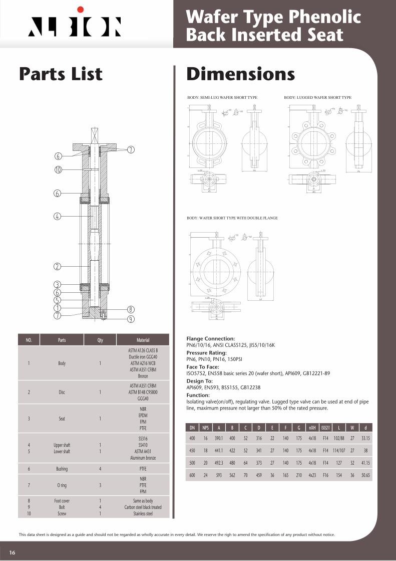
Wafer Type PhenolicBack Inserted Seat
11/2”-14” DN40-DN350 Features
1 ISO5211 Actuator Mount Flange
2 Anti Dust Seal Ring
3 O-Ring
4 Multi standard alignment holes: For connection between ANSI, EN or ISO standard fl anges.
5 Seat: Inserted seat with phenol back
6 High tolerance machined disc surfaces gives high effi cient seat, low operating torque and long seal life
7 Cotter pin retaining ring: Anti blow out of the shaft
8 Three bearings: To ensure perfect shaft turning and shaft centric position
9 Precision spline shaft and disc: To ensure positive connection of shaft and disc Give convenience to replacement
10 Threaded hole in lower shaft: For pulling out lower shaft when re-assembly.
11 Lower bearing
1 Body
2 Disc
3 Seat With Phenol Back
4 Upper Shaft
5 Lower Shaft
6 Bearing
7 O Ring
8 Split Pin
9 Retaining Ring
1
2
3
4
5
6
7
8
9
10
11
3
1
2
4
5
6
9
8
7
6
7
6
13
This data sheet is designed as a guide and should not be regarded as wholly accurate in every detail. We reserve the righ to amend the specifi cation of any product without notice.
Parts List Dimensions
NO. Parts Qty Material
1 Body 1
ASTM A126 CLASS BDuctile iron GGG40ASTM A216 WCBASTM A351 CF8M
Bronze
2 Disc 1ASTM A351 CF8M
ASTM B148 C95800GGG40
3 Seat 1
NBREPDMFPMPTFE
45
Upper shaftLower shaft
1 1
SS316SS410
ASTM A431Aluminum bronze
6 Bushing 4 PTFE
7 O ring 2 NBRPTFEFPM
89
Split pin Retainer ring
1 1
Carbon steelStainless steel
BODY: FULL WAFER SHORT TYPE BODY: SEMI-LUG WAFER SHORT TYPE
BODY: LUGGED WAFER SHORT TYPE BODY: WAFER SHORT TYPE WITH DOUBLE FLANGE
DN NPS A B C D E F G nXH ISO5211 L W d
40 1.1/2 42.6 133 19 70 11 70 90 4x10 f7 33 10 12.6
50 2 52.6 142 19 73.5 11 70 90 4x10 F7 43 10 12.6
65 2.1/2 64.4 155 19 80.5 11 70 90 4x10 F7 46 10 12.6
80 3 78.9 161 19 93 11 70 90 4x10 F7 46 10 12.6
100 4 104.1 180 19 110 11 70 90 4x10 F7 52 12 15.77
125 5 123.4 193 19 122.8 14 70 90 4x10 F7 56 14 18.92
150 6 155.96 205 19 139 14 70 90 4x10 F7 56 14 18.92
200 8 202.87 250 25 175 17 102 125 4x12 F10 60 17 22.1
250 10 250.88 282 40 208 22 102 125 4x12 F10 68 22 28.45
300 12 301.9 326 40 244 22 102 125 4x12 F10 78 24 31.6
350 14 334.01 358 40 270 22 102 125 4x12 F10 78 24 31.6
Flange Connection:PN6/10/16/25, ANSI CLASS125/150, JIS5/10/16KPressure Rating:PN6, PN10, PN16, PN25, 200PSI, 285PSI Face To Face:ISO5752, EN558 basic series20(wafer short), API609, GB12221-89Design To:API609, EN593, BS5155, GB12238 Function:Isolating valve(on/off), regulating valve. Lugged type valve can be used at end of pipe line, maximum pressure not larger than 50% of the rated pressure. PN25 ASTM A431 For PN25, the strength of shaft is not less than ASTM A431
Wafer Type PhenolicBack Inserted Seat
14

This data sheet is designed as a guide and should not be regarded as wholly accurate in every detail. We reserve the righ to amend the specifi cation of any product without notice.
16”-24” DN400-DN600Semi-Lug WaferShort Type
Size 16” -24” DN400-DN600
Temperature -40°C -210°C
Rating PN6/10/16, 150PSI
Body Cast iron, Ductile iron, Cast steel, Stainless steel
Disc Ductile iron, Cast steel, Stainless steel, Aluminum bronze, nickel plated, Nylon coated
Stem Carbon steel nickel plated, Stainless steel, High temperature alloy, Aluminum bronze
Seat NBR, EPDM, CSM, FPM, VSL, AU, CR, PTFE
Feature Bubble tight, zero leakage in both directions,
replaceable seat,maintenance free, easy alignment
Medium Potable water, Dirty water, High pure water, Sea water, Air, Gas, Steam, Oil, Pulp, Beer,
Powder
Size 16”-24” DN400-DN600
Temperature -40°C -210°C
Rating PN6/10/16, 150PSI
Body Cast iron, Ductile iron, Cast steel, Stainless steel
Disc Ductile iron, Cast steel, Stainless steel, Aluminum bronze, Nickel plated, Nylon coated
Stem Carbon steel nickel plated, Stainless steel, High temperature alloy, Aluminum bronze
Seat NBR, EPDM, CSM, FPM, VSL, AU, CR, PTFE
Feature Bubble tight, zero leakage in both directions,
replaceable seat,maintenance free,fi xed installation, suitable for end of line
Medium Potable water, Dirty water, High pure water, Sea water, Air, Gas, Steam, Oil, Pulp, Beer,
Powder
Size 16” -24” DN400-DN600
Temperature -40°C -210°C
Rating PN6/10/16, 150PSI
Body Cast iron, Ductile iron, Cast steel, Stainless steel
Disc Ductile iron, Cast steel, Stainless steel, Aluminum bronze, nickel plated, Nylon coated
Stem Carbon steel nickel plated, Stainless steel, High temperature alloy, Aluminum bronze
Seat NBR, EPDM, CSM, FPM, VSL, AU, CR, PTFE
Feature Bubble tight, zero leakage in both directions,
replaceable seat, maintenance free, easy alignment, suitable for end of line
Medium Potable water, Dirty water, High pure water, Sea water, Air, Gas, Steam, Oil, Pulp, Beer,
Powder
Lug Wafer Short Type
Double FlangedWafer Short Type
Features
1 ISO5211 Actuator Mount Flange
2 O-Ring
3 Multi standard alignment holes: For connection between ANSI, EN or ISO standard fl anges.
4 Replaceable seat with phenolic backing ring
5 High tolerance machined disc surfaces gives high effi cient seal, low operating torque and long seat life
6 Lower bearing
7 Anti Dust Seal Ring
8 Screw: Anti blow out of the shaft
9 Three bearings: To ensure smooth shaft turning and centralise shaft
10 Hexagonal shaft and disc: To ensure positive connection of shaft and disc
11 Bottom cover: For lower shaft replacement of large size valves
12 Anti Dust Seal ring
1 Body
2 Disc
3 Seat With Phenol Back
4 Upper Shaft
5 Lower Shaft
6 Bearing
7 O Ring
8 Bottom Cover
9 Bolt
10 Screw
1
2
3
4
5
6
7
8
9
10
11
12
3
1
2
4
5
6
9
7
7
6
10
8
7
6
Wafer Type PhenolicBack Inserted Seat
15
This data sheet is designed as a guide and should not be regarded as wholly accurate in every detail. We reserve the righ to amend the specifi cation of any product without notice.
Parts List Dimensions
DRAWINGS AND PARTS M
NO. Parts Qty Material
1 Body 1
ASTM A126 CLASS BDuctile iron GGG40ASTM A216 WCBASTM A351 CF8M
Bronze
2 Disc 1ASTM A351 CF8M
ASTM B148 C95800GGG40
3 Seat 1
NBREPDMFPMPTFE
45
Upper shaftLower shaft
11
SS316SS410
ASTM A431Aluminum bronze
6 Bushing 4 PTFE
7 O ring 3NBRPTFEFPM
89
10
Foot coverBolt
Screw
141
Same as bodyCarbon steel black treated
Stainless steel
DN NPS A B C D E F G nXH ISO5211 L W d
400 16 390.1 400 52 316 22 140 175 4x18 F14 102/88 27 33.15
450 18 441.1 422 52 341 27 140 175 4x18 F14 114/107 27 38
500 20 492.3 480 64 373 27 140 175 4x18 F14 127 32 41.15
600 24 593 562 70 459 36 165 210 4x23 F16 154 36 50.65
Flange Connection:PN6/10/16, ANSI CLASS125, JIS5/10/16K Pressure Rating:PN6, PN10, PN16, 150PSI Face To Face:ISO5752, EN558 basic series 20 (wafer short), API609, GB12221-89Design To:API609, EN593, BS5155, GB12238 Function:Isolating valve(on/off), regulating valve. Lugged type valve can be used at end of pipe line, maximum pressure not larger than 50% of the rated pressure.
BODY: SEMI-LUG WAFER SHORT TYPE BODY: LUGGED WAFER SHORT TYPE
BODY: WAFER SHORT TYPE WITH DOUBLE FLANGE
Wafer Type PhenolicBack Inserted Seat
16

This data sheet is designed as a guide and should not be regarded as wholly accurate in every detail. We reserve the righ to amend the specifi cation of any product without notice.
28”-48” DN700-DN1200Single FlangedWafer Short Type Size 28”-48” DN700-DN1200
Temperature -40°C -210°C
Rating PN6/10, 150PSI
Body Cast iron, Ductile iron, Cast steel, Stainless steel
DiscDuctile iron, Cast steel, Stainless steel,
Aluminum bronze, Nickel plated, Nylon coated
Stem Carbon steel nickel plated, Stainless steel, High temperature alloy, Aluminum bronze
Seat NBR, EPDM, CSM, FPM, VSL, AU, CR, PTFE
FeatureBubble tight, zero leakage in both directions,
replaceable seat, maintenance free, stable for installation
MediumPotable water, Dirty water, High pure water, Sea water, Air, Gas, Steam, Oil, Pulp, Beer,
Powder
Size 28”-48” DN700-DN1200
Temperature -40°C -210°C
Rating PN6/10, 150PSI
Body Cast iron, Ductile iron, Cast steel, Stainless steel
DiscDuctile iron, Cast steel, Stainless Steel,
Aluminum bronze, Nickel plated, Nylon coated
Stem Carbon steel nickel plated, Stainless steel, High temperature alloy, Aluminum bronze
Seat NBR, EPDM, CSM, FPM, VSL, AU, CR, PTFE
FeatureBubble tight, zero leakage in both directions,
replaceable seat, maintenance free, easy installation, suitable for end of line
MediumPotable water, Dirty water, High pure water, Sea water, Air, Gas, Steam, Oil, Pulp, Beer,
Powder
Double FlangedWafer Short Type
Features
1 Bare Shaft
2 O-Ring
3 Pinned Shaft: Ensure perfect shaft and disc connection for large size valve.
4 Replaceable Seat with phenolic backing ring
5 Bearing
6 Lower shaft plug: For lower shaft replacement of large size valve
7 ISO5211 Actuator Mount Flange
8 Anti dust O-ring
9 Three bearings: To ensure smooth shaft turning and centralise shaft
10 Lower bearing
11 Anti Dust O- ring
1 Body
2 Disc
3 Seat With Phenol Back
4 Upper Shaft
5 Lower Shaft
6 Bearing
7 O Ring
8 Bottom Cover
9 Bolt
10 Pin
11 Key
12 Bearing
1
2
3
4
5
6
7
8
9
10
11
1
2
3
4
5
6
7
12
8
9
6
7
11
10
7
6
6
10
Wafer Type PhenolicBack Inserted Seat
17

This data sheet is designed as a guide and should not be regarded as wholly accurate in every detail. We reserve the righ to amend the specifi cation of any product without notice.
Parts List Dimensions
NO. Parts Qty Material
1 Body 1
ASTM A126 CLASS BDuctile iron GGG40ASTM A216 WCBASTM A351 CF8M
Bronze
2 Disc 1ASTM A351 CF8M
ASTM B148 C95800GGG40
3 Seat 1
NBREPDMFPMPTFE
45
Upper shaftLower shaft
11
SS316SS410
ASTM A431Aluminum bronze
6 Bushing 4 PTFE
7 O ring 3NBRPTFEFPM
89
10 11
Foot coverBolt
Pin Bearing
1431
Same as bodyCarbon steel black treated
Stainless steel
DN NPS A B C D F G nXH ISO5211 L a b d h
700 28 694.9 624 82 528 254 300 8X18 F25 165 5 16 55 63
750 30 744.3 660 82 560 254 300 8X18 F25 165 5 16 55 63
800 32 795.6 672 82 600 254 300 8X18 F25 190 5 16 55 63
900 36 864 720 130 659 254 300 8X18 F25 203 6 20 75 100
1000 40 964 800 130 726 254 300 8X18 F25 216 7 22 85 125
1200 48 1160 951 150 868 298 350 8X23 F30 254 8 28 105 140
1400 56 1386 955 980 356 415 8X31 F35 279
1600 64 1586 1079 1096 406 475 8X37 F40 318
1800 72 1776 1176 1187 406 475 8X37 F40 356
2000 80 1976 1276 1287 406 475 8X37 F40 406
Flange Connection:PN6/10/16, ANSI CLASS125, JIS5/10/16K Pressure Rating:PN6, PN10, PN16, 150PSI Face To Face:ISO5752, EN558 basic series 20 (wafer short), API609, GB12221-89Design To:API609, EN593, BS5155, GB12238 Function:Isolating valve (on/off), regulating valve. Lugged type valve can be used at end of pipe line, maximum pressure not larger than 50% of the rated pressure.
BODY: WAFER SHORT TYPE WITH SINGLE FLANGE
BODY: WAFER SHORT TYPE WITH DOUBLE FLANGE
56” to 80” (DN1400-DN2000), 6 bar
Wafer Type PhenolicBack Inserted Seat
18
This data sheet is designed as a guide and should not be regarded as wholly accurate in every detail. We reserve the righ to amend the specifi cation of any product without notice.
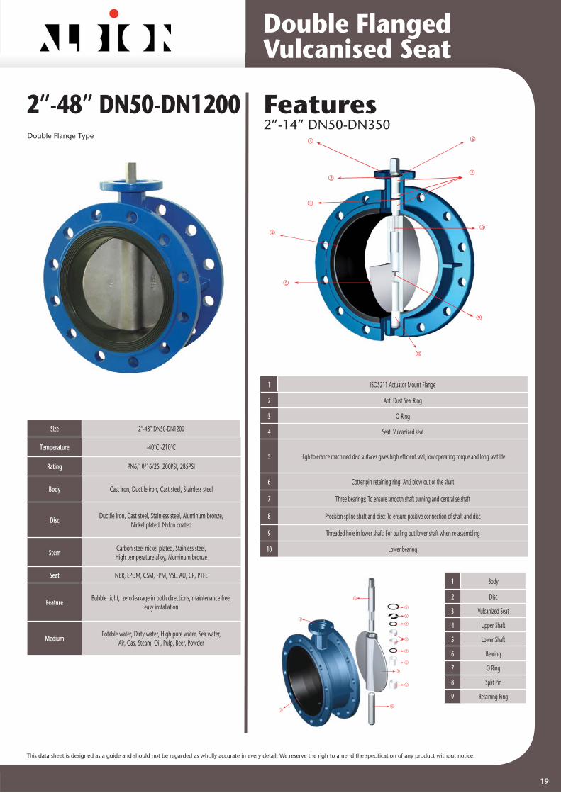
Features2”-14” DN50-DN350
Size 2”-48” DN50-DN1200
Temperature -40°C -210°C
Rating PN6/10/16/25, 200PSI, 285PSI
Body Cast iron, Ductile iron, Cast steel, Stainless steel
Disc Ductile iron, Cast steel, Stainless steel, Aluminum bronze,Nickel plated, Nylon coated
Stem Carbon steel nickel plated, Stainless steel,High temperature alloy, Aluminum bronze
Seat NBR, EPDM, CSM, FPM, VSL, AU, CR, PTFE
Feature Bubble tight, zero leakage in both directions, maintenance free,easy installation
Medium Potable water, Dirty water, High pure water, Sea water,Air, Gas, Steam, Oil, Pulp, Beer, Powder
Double Flange Type
2”-48” DN50-DN12001
2
3
4
5
6
7
8
9
10
1 ISO5211 Actuator Mount Flange
2 Anti Dust Seal Ring
3 O-Ring
4 Seat: Vulcanized seat
5 High tolerance machined disc surfaces gives high effi cient seal, low operating torque and long seat life
6 Cotter pin retaining ring: Anti blow out of the shaft
7 Three bearings: To ensure smooth shaft turning and centralise shaft
8 Precision spline shaft and disc: To ensure positive connection of shaft and disc
9 Threaded hole in lower shaft: For pulling out lower shaft when re-assembling
10 Lower bearing
1 Body
2 Disc
3 Vulcanized Seat
4 Upper Shaft
5 Lower Shaft
6 Bearing
7 O Ring
8 Split Pin
9 Retaining Ring
3
1
2
4
5
6
6
7
6
7
8
9
Double FlangedVulcanised Seat
19
This data sheet is designed as a guide and should not be regarded as wholly accurate in every detail. We reserve the righ to amend the specifi cation of any product without notice.
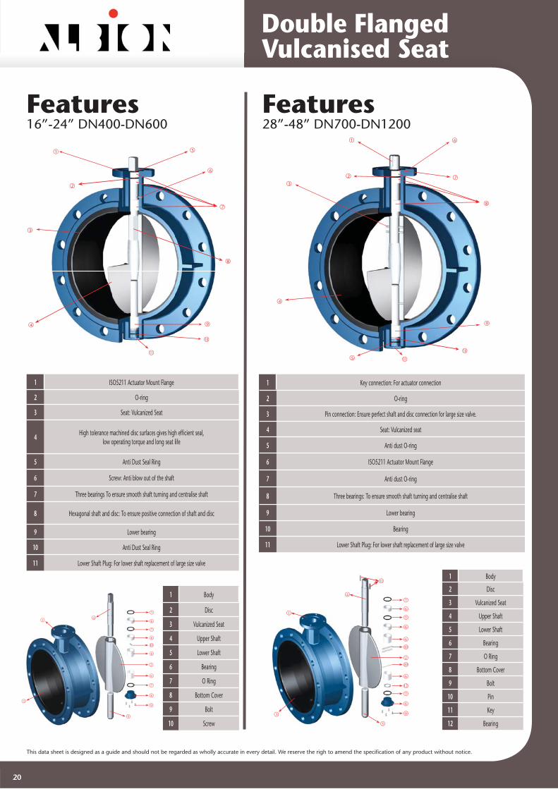
Features28”-48” DN700-DN1200
Features16”-24” DN400-DN600
1 Key connection: For actuator connection
2 O-ring
3 Pin connection: Ensure perfect shaft and disc connection for large size valve.
4 Seat: Vulcanized seat
5 Anti dust O-ring
6 ISO5211 Actuator Mount Flange
7 Anti dust O-ring
8 Three bearings: To ensure smooth shaft turning and centralise shaft
9 Lower bearing
10 Bearing
11 Lower Shaft Plug: For lower shaft replacement of large size valve
1 ISO5211 Actuator Mount Flange
2 O-ring
3 Seat: Vulcanized Seat
4 High tolerance machined disc surfaces gives high effi cient seal,low operating torque and long seat life
5 Anti Dust Seal Ring
6 Screw: Anti blow out of the shaft
7 Three bearings To ensure smooth shaft turning and centralise shaft
8 Hexagonal shaft and disc: To ensure positive connection of shaft and disc
9 Lower bearing
10 Anti Dust Seal Ring
11 Lower Shaft Plug: For lower shaft replacement of large size valve
1 Body
2 Disc
3 Vulcanized Seat
4 Upper Shaft
5 Lower Shaft
6 Bearing
7 O Ring
8 Bottom Cover
9 Bolt
10 Pin
11 Key
12 Bearing
1 Body
2 Disc
3 Vulcanized Seat
4 Upper Shaft
5 Lower Shaft
6 Bearing
7 O Ring
8 Bottom Cover
9 Bolt
10 Screw
1
2
3
4
5
6
7
8
9
10
11
3
1
2
4
5
6
9
7
7
10
8
7
6
6
6
1
2
3
4
5
6
7
8
9
10
11
1
2
3
4
5
6
7
8
9
6
7
11
10
7
6
6
10
12
Double FlangedVulcanised Seat
20

This data sheet is designed as a guide and should not be regarded as wholly accurate in every detail. We reserve the righ to amend the specifi cation of any product without notice.
Dimensions2”-14” DN50-DN350
Parts List2”-14” DN50-DN350
No. Parts Qty Material
1 Body 1
ASTM A126 CLASS BDuctile iron GGG40ASTM A216 WCBASTM A351 CF8M
Bronze
2 Disc 1ASTM A351 CF8M
ASTM B148 C95800GGG40
3 Seat 1
NBREPDMFPMPTFE
45
Upper shaftLower shaft
11
SS316SS410
ASTM A431Aluminium bronze
6 Bushing 4 PTFE
7 O ring 2NBRPTFEFPM
89
Split pinRetainer ring
11
Carbon steel Stainless steel
DN NPS A B C D E F G nxH ISO5211 L W d
50 2 52.6 124 19 83 11 70 90 4x10 F7 108 10 12.6
65 2.1/2 64.4 134 19 95 11 70 90 4x10 F7 112 10 12.6
80 3 78.9 141 19 102 11 70 90 4x10 F7 114 10 12.6
100 4 104.1 156 19 124 11 70 90 4x10 F7 127 12 15.77
125 5 123.4 168 19 137 14 70 90 4x10 F7 140 14 18.92
150 6 155.96 184 19 149 14 70 90 4x10 F7 140 14 18.92
200 8 202.87 205 25 170 17 102 125 4x12 F10 152 17 22.1
250 10 250.88 235 40 198 22 102 125 4x12 F10 165 22 28.45
300 12 301.9 280 40 220 22 102 125 4x12 F10 178 24 31.6
350 14 334.01 368 40 265 22 102 125 4x12 f10 190 24 31.6
Flange Connection:PN6/10/16/25, ANSI CLASS125/150, JIS5/10/16K Pressure Rating:PN6, PN10, PN16, PN25, 200PSI, 285PSI Face To Face:ISO5752, EN558 basic series 13(double fl anged short)Design To:API609, EN593, BS5155, GB12238 Function:Isolating valve (on/off), regulating valve. Double fl anged butterfl y valve can be used at end of pipe line, maximum pressure not larger than 50% of the rated pressure. PN25 ASTM A431 For PN25, the strength of shaft is not less than ASTM A431
Double FlangedVulcanised Seat
21

This data sheet is designed as a guide and should not be regarded as wholly accurate in every detail. We reserve the righ to amend the specifi cation of any product without notice.
Dimensions16”-24” DN400-DN600
Parts List16”-24” DN400-DN600
No. Parts Qty Material
1 Body 1
ASTM A126 CLASS B Ductile iron GGG40
ASTM A216 WCBASTM A351 CF8M
Bronze
2 Disc 1 ASTM A351 CF8M
ASTM B148 C95800GGG40
3 Seat 1
NBREPDMFPM PTFE
45
Upper shaftLower shaft
11
SS316 SS410
ASTM A431Aluminum bronze
6 Bushing 4 PTFE
7 O ring 2 NBRPTFE FPM
89
10
Foot CoverBolt
Screw
141
Same as body Carbon steel black treated
Stainless Steel
DN NPS A B C D E F G nXH ISO5211 L W d
400 16 390.1 340 52 282 22 140 175 4X18 F14 216 27 33.15
450 18 441.1 422 52 315 27 140 175 4X18 F14 222 27 38
500 20 492.3 430 64 348 27 140 175 4X18 F14 229 32 41.15
600 24 593 500 70 390 36 165 210 4X23 F16 267 36 50.65
Flange Connection:PN6/10/16, ANSI CLASS125, JIS5/10K Pressure Rating:PN6, PN10, PN16, 150PSI Face To Face:ISO5752, EN558 basic series 13(double fl anged short)Design To:API609, EN593, BS5155, GB12238 Function:Isolating valve (on/off), regulating valve. Double fl anged butterfl y valve can be used at end of pipe line, maximum pressure not larger than 50% of the rated pressure.
Double FlangedVulcanised Seat
22

This data sheet is designed as a guide and should not be regarded as wholly accurate in every detail. We reserve the righ to amend the specifi cation of any product without notice.
Dimensions28”-80” DN700-DN2000
Parts List28”-80” DN700-DN2000
No. Parts Qty Material
1 Body 1
ASTM A126 CLASS BDuctile iron GGG40ASTM A216 WCBASTM A351 CF8M
Bronze
2 Disc 1ASTM A351 CF8M
ASTM B148 C95800GGG40
3 Seat 1
NBREPDMFPM PTFE
45
Upper shaftLower shaft
11
SS316SS410
ASTM A431 Aluminum bronze
6 Bushing 4 PTFE
7 O ring 2NBRPTFEFPM
89
1011
Foot CoverBoltPin
Bearing
1431
Same as bodyCarbon steel black treated
Stainless Steel Steel
DN NPS A B C D F G nxH ISO5211 L a b d h
700 28 649.9 560 82 450 254 300 8x18 F25 292 5 16 55 63
750 30 744.3 640 82 540 254 300 8x18 F25 318 5 16 55 63
800 32 795.6 640 82 540 254 300 8x18 F25 318 5 16 55 63
900 36 864 665 130 540 254 300 8x18 F25 330 6 20 75 100
1000 40 964 735 130 620 254 300 8x18 F25 410 7 22 85 125
1200 48 1160 917 150 760 298 350 8x23 F30 470 8 28 105 140
1400 56 1386 955 980 356 415 8x31 F35 530
1600 64 1586 1079 1096 406 475 8x37 F40 600
1800 72 1776 1176 1187 406 475 8x37 F40 670
2000 80 1976 1276 1287 406 475 8x37 F40 760
Flange Connection:PN6/10/16, ANSI CLASS125, JIS5/10K Pressure Rating:PN6, PN10, PN16, 150PSI Face To Face:ISO5752, EN558 basic series 13(double fl anged short)Design To:API609, EN593, BS5155, GB12238 Function:Isolating valve (on/off), regulating valve. Double fl anged butterfl y valve can be used at end of pipe line, maximum pressure not larger than 50% of the rated pressure.
56” - 80” (DN1400-DN2000), 6 bar
Double FlangedVulcanised Seat
23

This data sheet is designed as a guide and should not be regarded as wholly accurate in every detail. We reserve the righ to amend the specifi cation of any product without notice.
2”-12” DN50-DN300Semi-Lug WaferShort Type Size 2”-12” DN50-DN300
Temperature -40°C -210°C
Rating PN6/10/16/25, 200PSI, 285PSI
Body Cast iron, Ductile iron, Cast steel, Stainless steel
DiscDuctile iron, Cast steel, Stainless steel,
Aluminum bronze, Nickel plated, Nylon coated
Stem Carbon steel nickel plated, Stainless steel, High temperature alloy, Aluminum bronze
Seat NBR, EPDM, CSM, FPM, VSL, AU, CR, PTFE
FeatureBubble tight, zero leakage in both directions,
replaceable seat,maintenance free, easy alignment
MediumPotable water, Dirty water, High pure water, Sea water, Air, Gas, Steam, Oil, Pulp, Beer,
Powder
Size 2” -12” DN50-DN300
Temperature -40°C -210°C
Rating PN6/10/16/25, 200PSI, 285PSI
Body Cast iron, Ductile iron, Cast steel, Stainless steel
DiscDuctile iron, Cast steel, Stainless steel,
Aluminum bronze, Nickel plated, Nylon coated
Stem Carbon steel nickel plated, Stainless steel, High temperature alloy, Aluminum bronze
Seat NBR, EPDM, CSM, FPM, VSL, AU, CR, PTFE
FeatureBubble tight, zero leakage in both directions,
replaceable seat,maintenance free,fi xed installation, suitable for end of line
MediumPotable water, Dirty water, High pure water, Sea water, Air, Gas, Steam, Oil, Pulp, Beer,
Powder
Lug Wafer Short Type
Features
1 ISO5211 Actuator Mount Flange
2 Anti Dust Seal Ring
3 O-Ring
4 Multi standard alignment holes: For connection between ANSI, EN or ISO standard fl anges.
5 Replaceable Seat
6 High tolerance machined disc surfaces gives high effi cient seal, low operating torque and long seat life
7 Cotter pin retaining ring: Anti blow out of the shaft
8 Three bearings: To ensure smooth shaft turning and centralise shaft
9 Precision spline shaft and disc: To ensure positive connection of shaft and disc Give convenience to replacement
10 Threaded hole in lower shaft: For easy extraction of lower shaft.
11 Lower bearing
1 Body
2 Disc
3 Elastomer Seat
4 Upper Shaft
5 Lower Shaft
6 Bearing
7 O Ring
8 Split Pin
9 Retaining Ring
1
23
4
5
6
7
8
9
10
11
3
1
2
4
5
6
6
7
6
7
8
9
Wafer Type (Short Neck) Replaceable Seat
24

This data sheet is designed as a guide and should not be regarded as wholly accurate in every detail. We reserve the righ to amend the specifi cation of any product without notice.
DimensionsParts List
No. Parts Qty Material
1 Body 1
ASTM A126 CLASS BDuctile Iron GGG40ASTM A216 WCBASTM A351 CF8M
Bronze
2 Disc 1ASTM A351 CF8M
ASTM B148 C95800GGG40
3 Seat 1
NBREPDMFPMPTFE
4 5
Upper shaftLower shaft
11
SS316SS410
ASTM A431Aluminum bronze
6 Bushing 4 PTFE
7 O ring 2NBRPTFEFPM
89
Split pinRetainer ring
11
Carbon SteelStainless Steel
DN NPS A B C D E F G nxH ISO5211 L W d
50 2 52.6 142 19 73.5 11 70 90 4X10 F7 43 10 12.6
65 2.1/2 64.4 155 19 80.5 11 70 90 4X10 F7 46 10 12.6
80 3 78.9 161 19 93 11 70 90 4X10 F7 46 10 12.6
100 4 104.1 180 19 110 11 70 90 4X10 F7 52 12 15.77
125 5 123.4 193 19 122.8 14 70 90 4X10 F7 56 14 18.92
150 6 155.96 205 19 139 14 70 90 4X10 F7 56 14 18.92
200 8 202.87 250 25 175 17 102 125 4X12 F10 60 17 22.1
250 10 250.88 282 40 208 22 102 125 4X12 F10 68 22 28.45
300 12 301.9 326 40 244 22 102 125 4X12 F10 78 24 31.6
Flange Connection:PN6/10/16/25, ANSI CLASS125/150, JIS5/10/16K Pressure Rating:PN6, PN10, PN16, PN25, 200PSI, 285PSI Face To Face:ISO5752, EN558 basic series 20 (wafer short), API609, GB12221-89Design To:API609, EN593, BS5155, GB12238 Function:Isolating valve(on/off), regulating valveLugged type valve can be used at end of pipe line, maximum pressure not larger than 50% of the rated pressure. PN25 ASTM A431 For PN25, the strength of shaft is not less than ASTM A431
BODY: SEMI-LUG WAFER SHORT TYPE
BODY: LUGGED WAFER SHORT TYPE
Wafer Type (Short Neck) Replaceable Seat
25

Distributor