Bushing Connector Application in Suspension Modeling John ... · Bushing Connector Application in...
22
Simulia Community Conference 2012 Bushing Connector Application in Suspension Modeling John Deere Turf and Utility Cary, North Carolina-USA Mukund Rao May 15~17, 2012 Simulia Community Conference, Providence RI
Transcript of Bushing Connector Application in Suspension Modeling John ... · Bushing Connector Application in...

Simulia Community Conference 2012
Bushing Connector Application in Suspension Modeling
John Deere Turf and UtilityCary, North Carolina-USA
Mukund RaoMay 15~17, 2012
Simulia Community Conference, Providence RI
Presentation Outline
1. Suspension assembly in utility vehicles – Overview
2. Coupled bushing-bolt joint construction
3. Ideal Modeling vs. Bushing Connector
4. ABAQUS documentation of bushing connector
5. Coupled bushing-bolt joint modeling
6. Bushing connector stiffness
7. Simplified suspension assembly analysis
8. TEST vs. Simulation correlation
9. Conclusions
Simulia Community Conference 2012
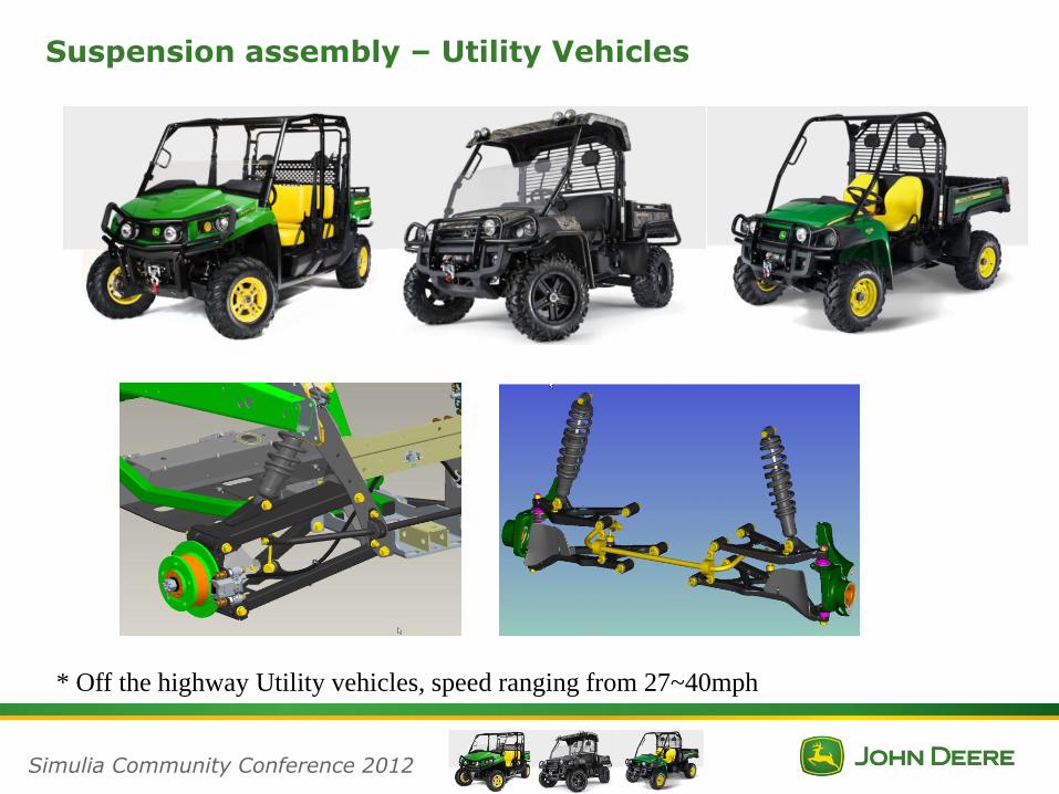
Suspension assembly – Utility Vehicles
* Off the highway Utility vehicles, speed ranging from 27~40mph
Simulia Community Conference 2012

Coupled Bushing-Bolt joint construction
•Bushing Construction has thin metal cylindrical structure with rubber sandwiched in-between•The rubber is already compressed and in a state of severe hyper-elastic strain•The Bushing is further hyper-elastically strained when clamped between the brackets
Simulia Community Conference 2012

Ideal Modeling vs. Bushing Connector
Solid geometry of the Bushing Joint
•Modeling to include rubber bushing with solid hyper elastic elements•All contacts defined with bolt joint modeled and pretension
Simulia Community Conference 2012

Suspension Modeling challenges
Bushing at severallocations in a simple rear suspension assembly
Simulia Community Conference 2012
* Extensive modeling and computationally challenging, if all bushings are modeled as solids along with details of bolt joint
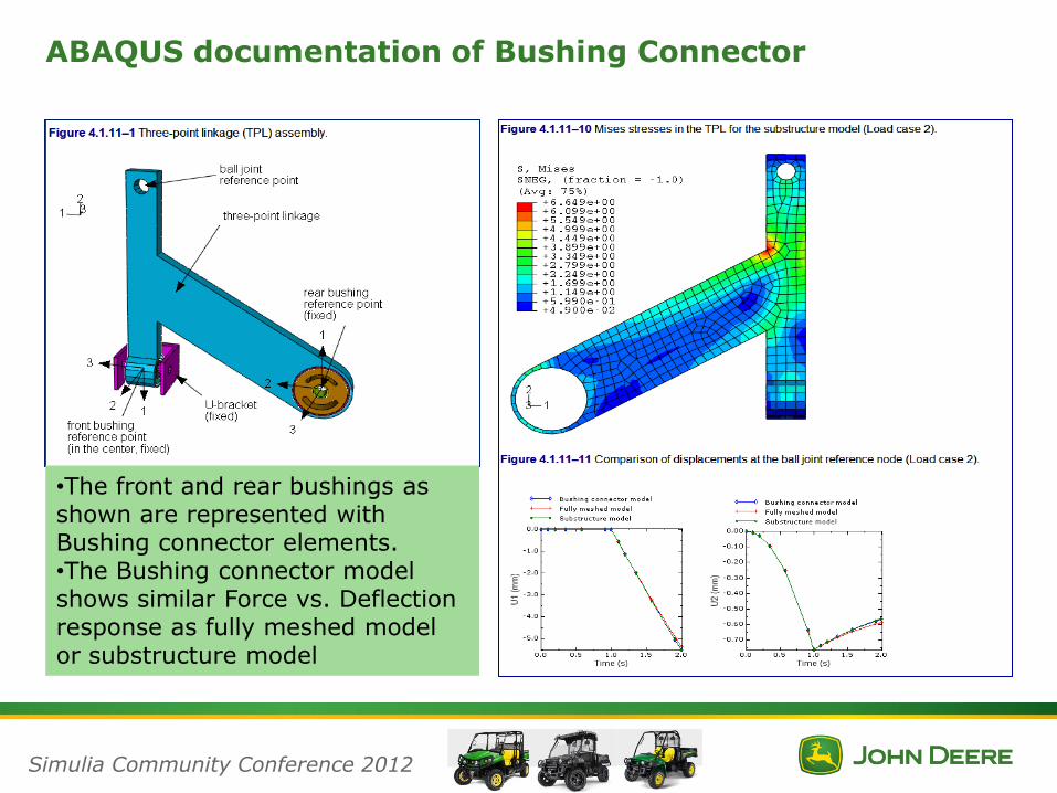
ABAQUS documentation of Bushing Connector
•The front and rear bushings as shown are represented with Bushing connector elements.•The Bushing connector model shows similar Force vs. Deflection response as fully meshed model or substructure model
Simulia Community Conference 2012

Coupled Bushing-Bolt Joint Modeling
Simulia Community Conference 2012
The contact surfaces represented for the hyper-elastic material bonded location and tied together with each node of bushing connector element
Bolt Joint modeled as Beam element or with solid element along with pretension
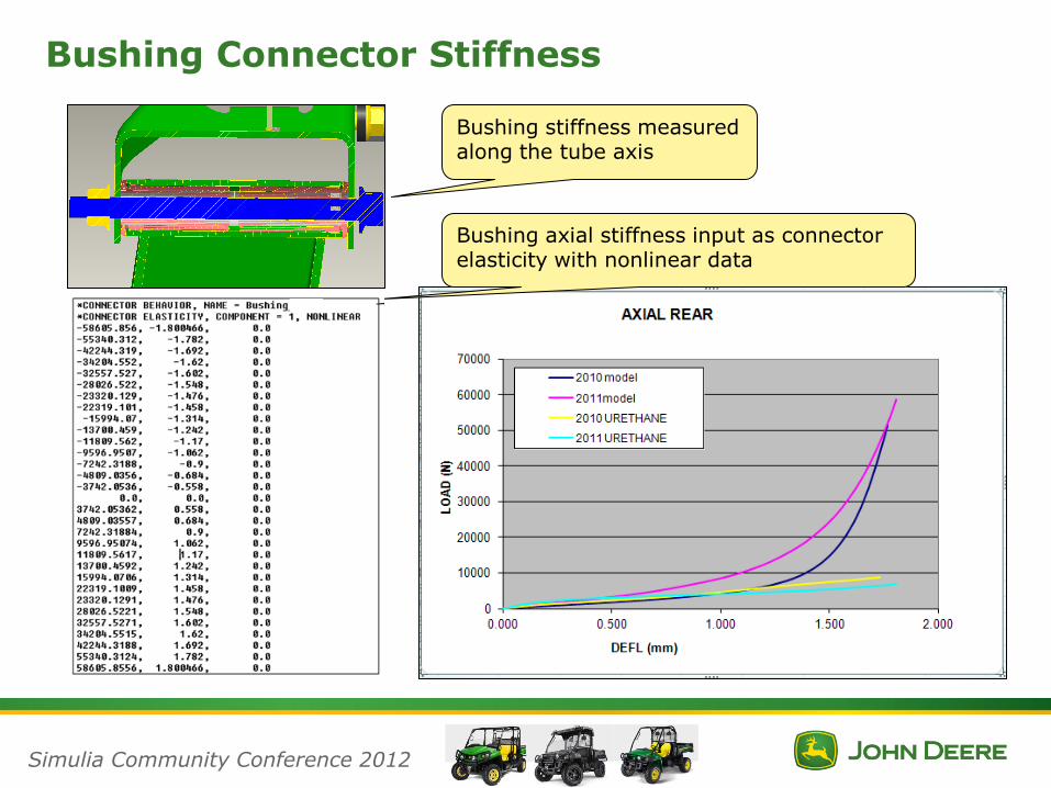
Bushing Connector Stiffness
Bushing stiffness measured along the tube axis
Bushing axial stiffness input as connector elasticity with nonlinear data
Simulia Community Conference 2012
Bushing Connector Stiffness
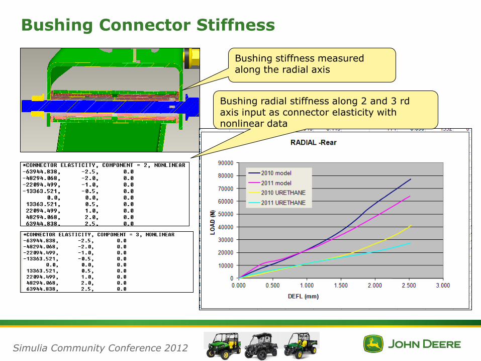
Bushing stiffness measured along the radial axis
Bushing radial stiffness along 2 and 3 rd axis input as connector elasticity with nonlinear data
Simulia Community Conference 2012
Bushing Connector Stiffness
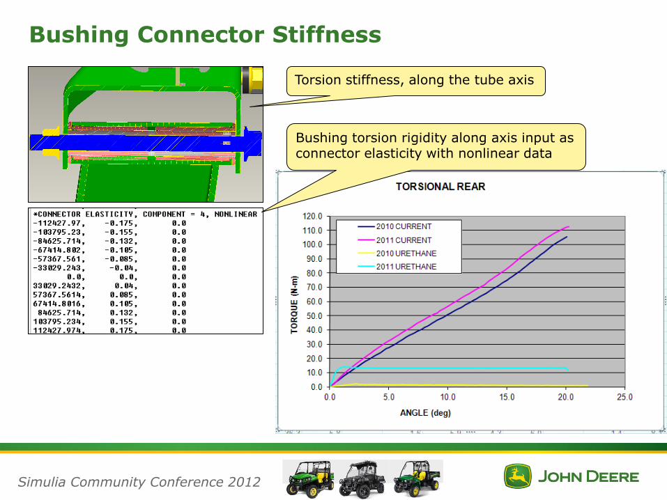
Torsion stiffness, along the tube axis
Bushing torsion rigidity along axis input as connector elasticity with nonlinear data
Simulia Community Conference 2012
Bushing Connector Stiffness
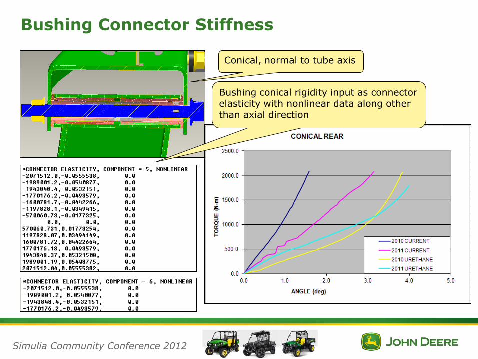
Conical, normal to tube axis
Bushing conical rigidity input as connector elasticity with nonlinear data along other than axial direction
Simulia Community Conference 2012

Simplified Suspension Assembly
The Bushing clamped at one of the upper arm fixed end
The shock replaced with rigid solid bar
FE Model with Bushing connector element and Bolt pretension
Simulia Community Conference 2012
Vertical Load TEST vs. FE
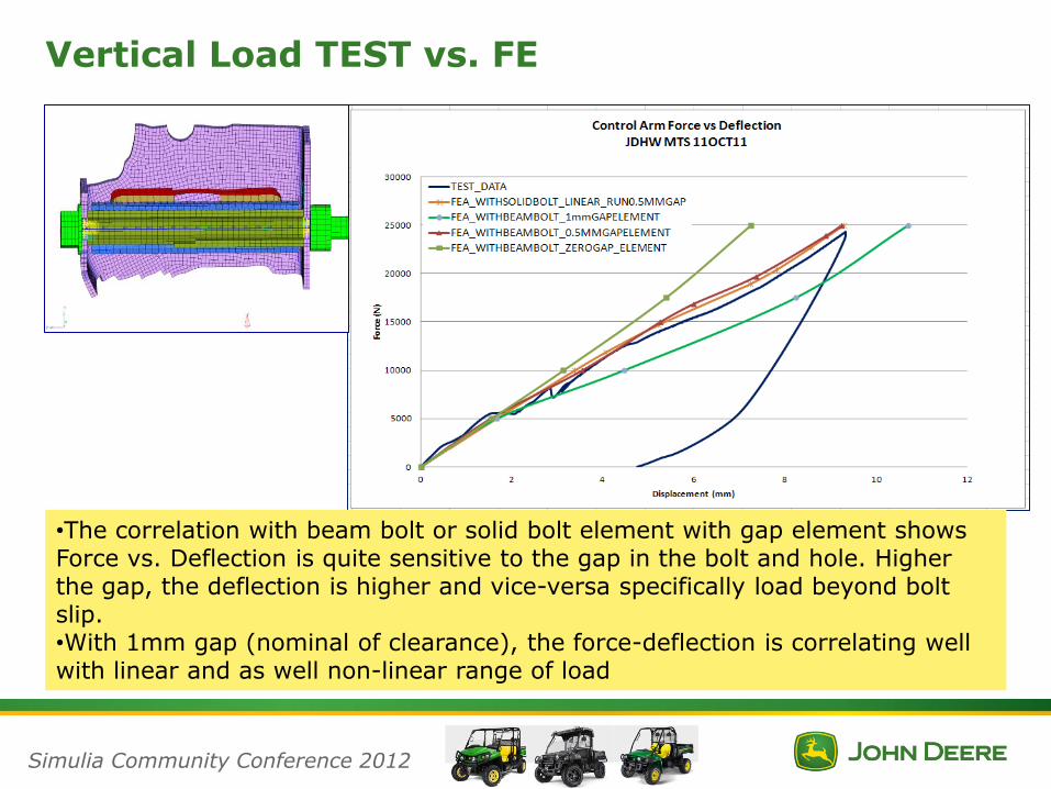
•The correlation with beam bolt or solid bolt element with gap element shows Force vs. Deflection is quite sensitive to the gap in the bolt and hole. Higher the gap, the deflection is higher and vice-versa specifically load beyond bolt slip.•With 1mm gap (nominal of clearance), the force-deflection is correlating well with linear and as well non-linear range of load
Simulia Community Conference 2012

Vertical Load TEST vs. FE
•The correlation with solid bolt element using linear or nonlinear run shows that the infection points are well correlated with peak load <3% variation between FE and TEST results.•The solid bolt element nonlinear run modeled with assumed gap, shows some deviation for load beyond 10kN, as oppose to linear run likely due to varied plasticity in the bolt contact area•Also some deviation are seen in the unloading region likely due to stress relaxation in bushing.
Simulia Community Conference 2012
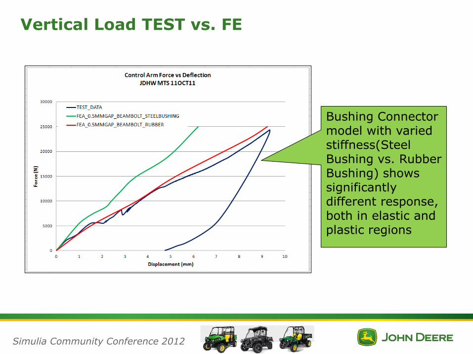
Vertical Load TEST vs. FE
Simulia Community Conference 2012
Bushing Connector model with varied stiffness(Steel Bushing vs. Rubber Bushing) shows significantlydifferent response, both in elastic and plastic regions

Lateral Load Stiffness
Simulia Community Conference 2012

Lateral Load TEST vs. FE
•The correlation with solid bolt element using linear or nonlinear run shows again a very close response between FE and TEST results
Simulia Community Conference 2012

Fore-aft Load Stiffness
Simulia Community Conference 2012

Fore-aft Load TEST vs. FE
•The correlation with beam model element shows good correlation, while the setup may not be suited with rigid shock as parallel load path.
Simulia Community Conference 2012

Summary
1. The Bushing connector element available in ABAQUS standard/explicit has
shown excellent response of Force-Deflection, when correlated between
Simulation and TEST results.
2. The modeling of Bushing connector element with measured stiffness is simple
and complete with nonlinear range.
3. The Bushing connector application in suspension modeling is very useful and
makes solving computationally less intensive.
4. The Bushing connector application also helps to understand the influence of
numerous variables on coupled bushing-bolt joint connections. This is very
significant to understand the suspension assembly parts under peak loads.
5. The measured bushing stiffness is more appropriate, while estimated/simulated
is applicable for new designs in bushing for varied stiffness. However if
bushings are used with bolt pretension, than the bushing stiffness
measurement to include the bolt pretension. The axial stiffness in bushing
seems to see impact from bolt pretension load.
Simulia Community Conference 2012

Simulia Community Conference 2012