Busbar Component Adapters for modern industrial · PDF file Circuit-breakers NZM...
20
www.moeller.net Circuit-breakers NZM Circuit-breakers IZM Switchboard systems Contactors DIL Motor-protective circuit-breakers PKZ Motor-starters MSC Busbar Component Adapters for modern industrial control panels Technical Paper Dipl.-Ing. Wolfgang Esser For Moeller Electric Sales and Support call KMparts.com (866) 595-9616
Transcript of Busbar Component Adapters for modern industrial · PDF file Circuit-breakers NZM...

www.moeller.net
Circuit-breakersNZM
Circuit-breakersIZM
Switchboard systems
Contactors DIL
Motor-protectivecircuit-breakers PKZ
Motor-starters MSC
Busbar Component Adapters for modern industrial control panels
Technical PaperDipl.-Ing. Wolfgang Esser
For Moeller Electric Sales and Support call KMparts.com (866) 595-9616

2
Dipl.-Ing. Wolfgang EsserManager, Product Support Industrial DevicesDivision Circuit Breakers, Motorstarters and DrivesMoeller GmbH, Bonn
With grateful acknowledgment of the support from:Mr. Andre R. Fortin, BA Phys.Manager - Codes & StandardsInternational Corporate Advisor – Power ProductsMoeller Electric Corporation, Millbury, Massachusetts, USAandMr. Dieter Reiß, Dipl.-Ing.Institute for International Product Safety GmbH, Bonn
Busbar Component Adapters– for modern industrial control panel assembly in full compliance with North American market requirements –
Different kinds of switching cabinets
The demands placed on modern engi-neered assembly designs, includingmounting and wiring techniques, downto the way in which current within theassembly is distributed, are very varied.Major differences are encountered as aresult of:
• The end-use application of theassembly.
• Its configuration, geometrical layoutand type of housing.
• Its maximum rated current, • and of course, the physical size of the
components to be mounted within.
Generally speaking, they can be brokendown into two distinct groupings
• Energy Distribution assemblies, or • Electrical apparatus for machinery
(Machines and machine tool controls, with integrated power switching and protective components)
Additional structural differences arenoted in energy distribution assembliesfalling under the DIN EN 60439-1 [1]standard, such as those found in:
• Industrial and commercial applications, as well as in
• the infra-structure of residential living complexes.
In turn, these various types of engineeredassemblies generally feature a differentapproach with respect to the way inwhich current or energy is distributedwithin their housing or enclosure groupings. Typical for energy distributionassemblies would involve a number ofsections, each reflecting a high degreeof standardization in order to moreeasily fulfill the requirements of TSK1-resp. TTA2-Type tested assemblies (Referto Table 1). In industrial applications,a greater mix of motor starter contentand/or serial groupings of smallercomponents addressing lesser loadsare often encountered in energy
distribution sections. Assemblies whichmainly feature motor starters makeuse of a withdrawable drawer designsystem in a high density configuration,from which one or even two loads perunit can be effectively controlled(MCCs3-Motor Control Centers). Thisdesign features complete drawer unitsdirectly plugged into a set of feedervertical busbars. This technology allowsfor quick replacement of damaged unitsin down time critical applications suchas is encountered in the chemical or rawmaterial processing industries.
Assemblies with an inherently highercontent of control circuit functionality(e.g. Electrical apparatus for industrialmachinery) are more likely to requireindividual and customized designengineering since there is often theneed for those particular applicationsto take into account specific and safetyoriented requirements. These would bespelled out in relevant electrical designstandards for machinery, such as IEC/EN60 204-1 [2] in the IEC world and NFPA79 (Electrical Standard for IndustrialMachinery) in North America. Theseparticular assemblies, commonly referredto as Industrial Control Panels andIndustrial Control Panels for IndustrialMachinery very often need to placehigher demands on the design andapplication versatility of their installedcomponents, particularly in the caseof serially built machinery. It’s quitecommon for those to be built andwarehoused ahead of time, before an
Differences abound in the types of engineered assemblies encountered throughout the market
Table 1: Necessary Type testing per IEC/EN 60 439-1can be made easier for manufacturers of switchgearassemblies by standardizing on distribution boardcontent.
Type testing for Type tested assemblies (TSk) per IEC/EN 60 439-1
• Verification of the short circuit withstand strength,
• Verification of temperature-rise limits,• Verification of the continuity of the
protective circuit,• Verification of clearances and creepage
distances,• Verification of the dielectric properties,• Verification of mechanical operation,• Verification of the degree of protection• And additional verifications.
1 TSK = Typ Tested Assemblies in accordance with EN 60439-12 TTA = Type Tested Assemblies3 MCC = Motor Control Center
For Moeller Electric Sales and Support call KMparts.com (866) 595-9616

3
order is actually placed and the finalend-use destination can be determined.This puts a premium on the availabilityof components which incorporate theessential features necessary to makethem fully compliant with pertinentapproval agencies world-wide and thusinsure their global application withoutrestriction. Variations in standardized
design should be avoided wheneverand wherever possible, if anything sothat administrative costs can be keptdown to an absolute minimum. Thebusbar systems and adapters describedin the following pages are optimallydesigned to provide modern andrational solutions for industrial controlpanels used in those applications.
We often see today a differentiationbetween centralized and de-centralizedcontrol and energy distribution concepts.These 2 approaches place differentrequirements on associated housingsand are usually configured differentlywith respect to the number of components per enclosure, as well as to the magnitude of current levels
Table 2: There is more discussion today on the subject of centralized vs. decentralized installation designs. Besides the usual systematic pro and con break-down of aspects from both, a conceptual solution can also be influenced by the way in which varying energy distribution methods and mounting systemscan be applied.
Application possibilities for energy distribution systems as a function of the size, space requirement and functionality of the equipment
Assembly concept Arrange-ment of power switchingand protective devices
Centralized electrical equipment
De-centralized electrical equipment
Arrangementspatious and functional
Grouped as a unit spatious and/or functionallyseparate (e.g. load centers)
Close to load, load basedarrangement
Examples: Machinery equipment Water treatment equipment Conveyor belt or rollertechnology
Power rating [kW]per Unit (Enclosure)
Large power demand, withmany loads, some of whichcan be particularly large
Lesser power requirements,smaller number of loads,noticeable amount of loadcenters in some cases
Mostly small individual loads,often of the same type
Energy supply Single point supply sourcevia cable or bus system
Single point supply sourcevia cable or bus system
Distributed supply sourcevia solid or flexible buswaysystem
Current distribution inindividual enclosures
Preferably via busbar system,partly supplemented withbus link connectors
Preferably via busbar system,partly supplemented withbus link connectors
Direct supply of motor starters,starter groupings will alsofeature bus link connectors
Mounting of motor startersup to 15 kW
On busbar adapters,or mounting rails,or mounting rail adapters
On busbar adapters,or mounting rails,or mounting rail adapters
On mounting rails,or mounting rail adapters
Motor protective switch andcircuit breaker mounting
On busbar adapters, possibleup to 550 A, or on mountingand modular plates
On busbar adapters, possibleup to 550 A, or on mountingand modular plates
On mounting rails ormounting rail adapters,or mounting plates
Arrangement of actuating,input and display devices
Local, application oriented Local, application oriented Often integrated indecentralized enclosures, alsoadditional centralized operatorand display station present
Information- and Signallingexchange
Increasingly viacommunication bus system
Increasingly viacommunication bus system
Primarily via communicationbus system
Special advantages Optimum clarity of design,reduced demands on enclosuremethods
Optimized cabelingrequirements, higher degreeof flexibility for changes
Higher level of standardizing,especially useful in cabelingrequirements, higher degreeof flexibility for changes, plugtechnology for all electricalconnections is common
For Moeller Electric Sales and Support call KMparts.com (866) 595-9616
4
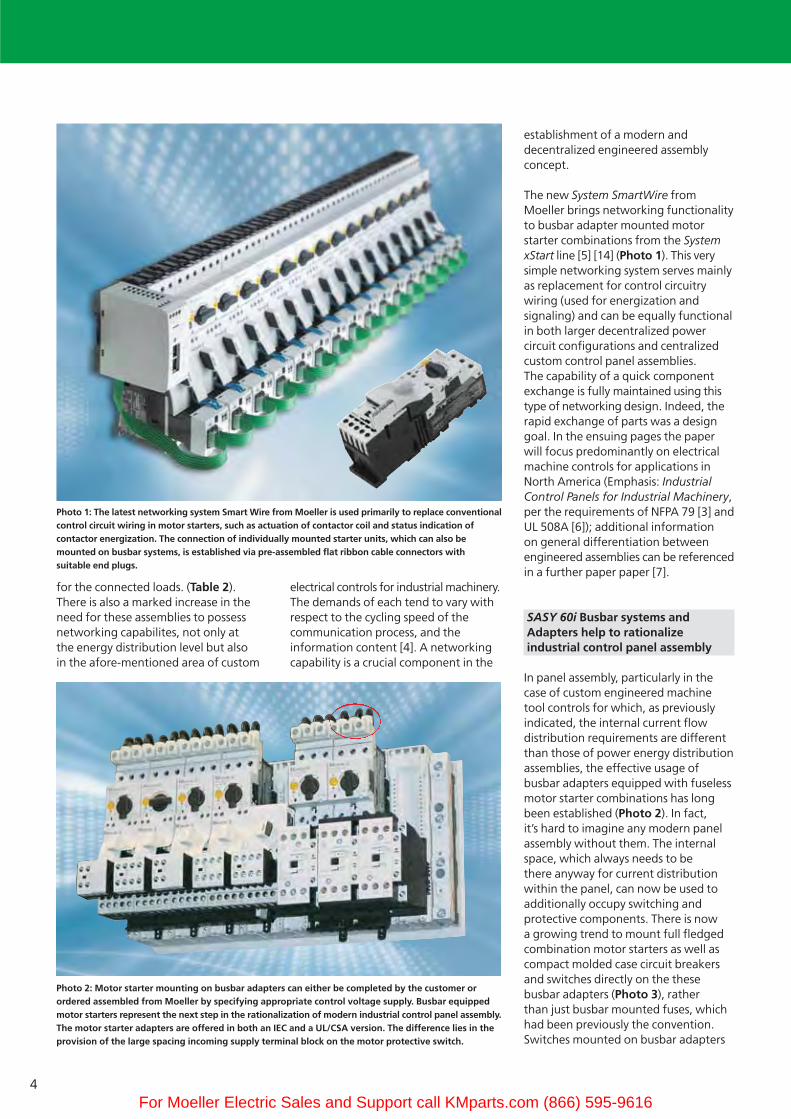
for the connected loads. (Table 2). There is also a marked increase in theneed for these assemblies to possessnetworking capabilites, not only at the energy distribution level but also in the afore-mentioned area of custom
electrical controls for industrial machinery.The demands of each tend to vary withrespect to the cycling speed of the communication process, and the information content [4]. A networkingcapability is a crucial component in the
establishment of a modern and decentralized engineered assembly concept.
The new System SmartWire from Moeller brings networking functionalityto busbar adapter mounted motor starter combinations from the SystemxStart line [5] [14] (Photo 1). This verysimple networking system serves mainlyas replacement for control circuitrywiring (used for energization andsignaling) and can be equally functionalin both larger decentralized power circuit configurations and centralizedcustom control panel assemblies. The capability of a quick componentexchange is fully maintained using thistype of networking design. Indeed, therapid exchange of parts was a designgoal. In the ensuing pages the paperwill focus predominantly on electricalmachine controls for applications inNorth America (Emphasis: IndustrialControl Panels for Industrial Machinery,per the requirements of NFPA 79 [3] andUL 508A [6]); additional informationon general differentiation betweenengineered assemblies can be referencedin a further paper paper [7].
SASY 60i Busbar systems and Adapters help to rationalize industrial control panel assembly
In panel assembly, particularly in thecase of custom engineered machinetool controls for which, as previouslyindicated, the internal current flowdistribution requirements are differentthan those of power energy distributionassemblies, the effective usage ofbusbar adapters equipped with fuselessmotor starter combinations has longbeen established (Photo 2). In fact,it’s hard to imagine any modern panelassembly without them. The internalspace, which always needs to bethere anyway for current distributionwithin the panel, can now be used toadditionally occupy switching andprotective components. There is nowa growing trend to mount full fledgedcombination motor starters as well ascompact molded case circuit breakersand switches directly on the thesebusbar adapters (Photo 3), ratherthan just busbar mounted fuses, whichhad been previously the convention.Switches mounted on busbar adapters
Photo 1: The latest networking system Smart Wire from Moeller is used primarily to replace conventionalcontrol circuit wiring in motor starters, such as actuation of contactor coil and status indication of contactor energization. The connection of individually mounted starter units, which can also be mounted on busbar systems, is established via pre-assembled flat ribbon cable connectors with suitable end plugs.
Photo 2: Motor starter mounting on busbar adapters can either be completed by the customer or ordered assembled from Moeller by specifying appropriate control voltage supply. Busbar equippedmotor starters represent the next step in the rationalization of modern industrial control panel assembly.The motor starter adapters are offered in both an IEC and a UL/CSA version. The difference lies in theprovision of the large spacing incoming supply terminal block on the motor protective switch.
For Moeller Electric Sales and Support call KMparts.com (866) 595-9616

5
serve mainly as incoming feeder orbranch circuit components and canaccommodate loads in the vicinity of550 to 600 A.Current levels in machine tool controlsand industrial control panels aregenerally lower, and the significanceof protective functions tends to besomewhat less critical, than for typicalenergy distribution assemblies. Onthe other hand, requirements for loadswitching devices are comparativelygreater and more varied. Contactorsfacilitate automatic and remoteswitching of power loads and thusfulfill an additional, and vital, role forthose assemblies. In short, electricalcontrol panels such as those for industrialmachinery and the like will be associatedwith a greater need for innovativecomponent mounting and wiringmeans. Moeller raises the functionalityof busbar adapters in industrial controlpanels to new levels by making factoryassembled and connection ready busbaradapter sets equipped with top mountedcombination motor starters readily available as off-the shelf components(Photo 2). This virtually eliminates themounting and wiring time which wouldhave been neccessary in the local panelshop or at the end-use location, andthus drastically cuts down the amountof potentially costly errors which oftenoccur in those types of assemblies.Thetask of providing a control panel shortcircuit rating (Short Circuit CurrentRating, SCCR [8]), which representsa new feature in North american industrial control panels, is madea whole lot easier by the availability
of these fully rated and approved multi-function modules from a singlemanufacturer. These multi-functionunits go a long way in efficiently fulfilling current distribution, protection,switching and signalling functions, all in one package. They can even gofurther towards the establishment of an optimum solution by incorporatingaccessories to enable padlocking andnetworking capabilites.
Special busbar system requirements for applications in North America
World wide, demands for busbarsystems with respect to nominal currentcarrying capacities, voltage levels, andshort circuit ratings, have been on theincrease, even in the domain of industrialcontrols and machinery. A high faultshort circuit withstand rating, a relativelyhigh nominal current rating of 550 A foran adapter mounted circuit breaker, a600 V, 60 Hz voltage rating for Canadaand an even higher 690 V 50 Hz ratingfor applications per IEC standards haveposed absolutely no problems for thesebusbar system innovations.
A number of challenging designchanges to the IEC version of the busbaradapter needed to be addressed beforea successful introduction into theNorth American marketplace could becontemplated. As Photo 4 illustrates,the bus itself, the adapters, and theterminal connector block on theincoming side of the motor protectiveswitch mounted on the adapter liemostly in the feeder circuit of IndustrialControl Panels. In North America, thisparticular area of the circuit generally
Photo 4: The knowledge of a few key definitions is necessary in order to properly understand theapplication of electrical clearances in North America. Every installation includes a supply circuit networkreferred to as the “Feeder Circuit“ , which starts at the point of supply after the service (e.g. the distribution panel in a house, or the supply to a machine as shown above), and ends on the load sideof “Branch Circuit Protective Devices“ . The area is indicated in yellow in the diagram and is subjectto the application of large distribution spacings (Distribution Equipment). In the example shownabove, the busbar system and adapters are effectively located in the feeder circuit. Only in the“Branch Circuit“ portion of the circuit (shown in green) would the smaller industrial control clearancesper UL 508 be allowed (Industrial Control Equipment).
Photo 3: It has become possible in the meantime to design adapters which allow mounting of circuitbreakers or molded case switches, rated up to 550 A and used in incoming or outgoing circuits, directlyonto the busbar system. The actuation possibilites for the switches can also be varied, from manualmeans to remote switching via an electrical motor operator, or even through a flex cable and sidehandle accessory typical of North American installations.
�
Main distributionsystem
or
or
Incoming switch
Load side
Main Switch
Branch Circuit Protective Device
Busbar system
Industrial control panel
Feeder CircuitsLarge creepage andclearance distances
Branch CircuitsSmall creepage and clearance distances
For Moeller Electric Sales and Support call KMparts.com (866) 595-9616
6
requires larger distribution electricalclearances on component field terminations, i.e. distances of an 1” (1 Inch = 25,4 mm) through air and2” (2 Inches = 50,8 mm) over surfacebetween terminals and points of opposite polarity for circuits up to 600V.A clearance over surface of at least 1“ would also be required betweenuninsulated live parts and any groundedmetal surface such as a mounting plateor an enclosure wall. Those are the typical clearances encountered in energydistribution equipment and which subsequently became part of the construction requirements for Type Eand Type F Combination Motor Controllers, described in greater detaillater in the paper. A number of changesin the North American electrical standards had helped establish morecomprehensive testing of IEC stylemanual motor starters and enabled better utilization of their protective characteristics in that market. Part ofthese developments required the largerclearances typically found on the terminations of molded case circuit breakers per UL 489 [9] to become partof the UL 508 [10] component standardTable 76.3 for those components. Busbar systems and adapters describedherein are typically installed in IndustrialControl Panels per UL 508A and arethus generally covered under the UL508 Industrial Control component standard. Some of their internal designaspects may not fully meet the full construction requirements of energydistribution assemblies such as Panelboards (UL 67 [11]) and Dead-Front Switchboards (UL 891 [12]) andthus they are normally considered unsuitable for those applications.
Design engineers involved with busbarsystems should be mindful that not allassemblies available on the markettoday carry the necessary approvals to insure a trouble-free installation inNorth America, and furthermore, thatthe process of selecting the right busbarsystem for the application is not alwaysso readily apparent. Busbar systemswhich are neither approved nor certifiedshould be immediate taboo to anyinternational machine manufacturerand panel builder (OEM) with exportplans to North America. Moeller’s mainline of busbar systems and adapters is deemed to be a “World Market”
offering, since it encompasses all of thepertinent approvals necessary for globalmarkets. Because of varying productioncost levels, Moeller still does offer a lineof busbar holders and componentequipped bus adapters which are notspecifically approved for North America.However, it’s definitely worth consideringwhether a doubling of the inventory withunapproved parts would make any sense economically, given that theapproved model provides the additional,and risk minimizing, benefit of beinguniversally acceptable in all markets.Standardizing on world-market components also eliminates any potential mixup of parts from occurringin a given shipment, which in itselfcould prove to be very costly.
The challenge presented to the manufacturer by the need to providelarger electrical clearances on components was solved easily enoughthrough constructive changes, albeit at a substantial cost when taking intoaccount the investment in componentre-design and the associated follow-uptesting necessary to validate the changes.Although the design engineer must stillconsider certain factors peculiar toNorth American installations, such aslarger clearances between live parts andgrounded metal in the control panelenclosure, he is at least helped by the fact that, through extensive typetesting, the ampacity levels of the bus system are able to be matched up exactly with corresponding IEC ratings.
In the US, busbar ampacities which havenot otherwise been established throughtesting can be conservatively determined
by the equivalence of 1000 A/Inch2, or roughly 1,55 A/cm2, using metricmeasurements. The formula has been in place for years and can also be foundin the UL 508A standard for IndustrialControl Panels. Unfortunately, theampacity values determined by usingthis formula often turn out to be veryconservative, leading to large discre-pancies between permissible UL and IEC bus ampacity levels. However, thisdifferential can be overcome throughcomprehensive testing of the busassembly. The advantages of reachingparity between UL and IEC values canbe significant, enabling machine designand panel layout, at least from the bus system’s point of view, to be uniformand applicable in both markets. A vital consideration for machine manufacturers who export world-wide!
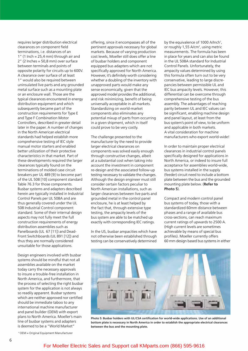
In order to maintain proper electricalclearances in industrial control panelsspecifically designed for applications inNorth America, or indeed to insure fullacceptance for assemblies world-wide,bus systems installed in the supply(feeder) circuit need to include a bottomplate between the bus and the groundedmounting plate below. (Refer toPhoto 5).
Compact and modern control panel bus systems of today, those with a standardized 60mm distance betweenphases and a range of available buscross-sections, can reach maximum current ratings of upwards to 2500 A.(High current levels are sometimesachievable by means of special bus profiles). Moeller currently offers 60 mm design based bus systems in either
Photo 5: Busbar holders with UL/CSA certification for world-wide applications. Use of an additionalbottom plate is necessary in North America in order to establish the appropriate electrical clearancesbetween the bus and the mounting plate.
4 OEM = Original Equipment Manufacturer
For Moeller Electric Sales and Support call KMparts.com (866) 595-9616
7
flat copper or special profile configurations for current levels up to 1600 A.
A comprehensive selection of accessoriesfacilitates the incoming supply connections and enhances shock hazard protection. Unused sections ofexposed bus reserved for subsequentcircuit additions can be safely and easilycovered. It’s also possible today, in addition to the use of bus adapters for components such as motor starters, to mount compact NZM molded casecircuit breakers and PN, N oder NSmolded case switches in similar fashiondirectly onto busbar systems. These canreach current levels on the order of 550 Aand can be used either as incoming supply disconnecting means or for theprotection and/or isolation of outgoingcircuits. It is recommended that theincoming switch, in spite of it beingmounted directly onto a bus system,also be equipped with an incoming line terminal shield, which is readily
available as an accessory for such purposes. For North American assemblies it’s also a good idea to provide adequate spacing between the supply disconnecting means andoutgoing feeder and motor starter circuits, as a means to visually distinguishbetween incoming and outgoingpower circuits.
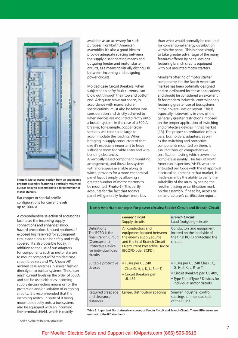
Molded Case Circuit Breakers, whensubjected to hefty fault currents, canblow out through their top and bottomend. Adequate blow-out space, inaccordance with manufacturer specifications, must also be taken intoconsideration and strictly adhered towhen devices are mounted directly ontoa busbar system. In the case of a 500 Abreaker, for example, copper cross-sections will tend to be large to accommodate the loading. When bringing in supply conductors of thatsize it’s especially important to leavesufficient room for cable entry and wirebending clearances. A vertically based component mountingarrangement, and thus a bus systemwith more space available along itswidth, provides for a more economicalpanel layout simply by allowing a greater number of motor starters to be mounted (Photo 6). This partlyaccounts for the fact that today’s panel will generally feature more bus
than what would normally be requiredfor conventional energy distributionwithin the panel. This is done simply to take greater advantage of the manyfeatures offered by panel designs featuring branch circuits equipped with bus mounted motor starters.
Moeller’s offering of motor starter components for the North Americanmarket has been optimally designedand co-ordinated for these applicationsand should be considered an excellentfit for modern industrial control panelsfeaturing greater use of bus systems in their overall design layout. This isespecially noteworthy in view of thegenerally greater restrictions imposedon the proper application of switchingand protective devices in that market[13]. The proper co-ordination of busbars, bus holders, adapters, as well as the switching and protective components mounted on them, is assured through comprehensive certification testing which covers thecomplete assembly. The task of NorthAmerican inspectors (AHJ5), who are entrusted per Code with the of approvalelectrical equipment in that market, ismade easier by the ability to verify thesuitability of the array by seeing theresultant listing or certification mark on the assembly. If need be, access toa manufacturer’s certification report,
Photo 6: Motor starter section from an engineeredproduct assembly featuring a vertically mountedbusbar array to accommodate a large number ofmotor starters.
Table 3: Important North American concepts: Feeder Circuit and Branch Circuit. These differences arenot part of the IEC standards.
North American concepts for power circuits: Feeder Circuit and Branch Circuit
Feeder CircuitSupply circuits
Branch CircuitLoad (outgoing) circuits
DefinitionsThe BCPD is thefinal Branch Circuit(Overcurrent)Protective Devicefor individual loadcircuits
All conductors andequipment located betweenthe energy supply sourceand the final Branch CircuitOvercurrent Protective Device(BCOPD oder BCPD).
Conductors and equipmentlocated on the load side ofthe final BCPD protecting thecircuit.
Suitable protectivedevices
• Fuses per UL 248
Class G, H, J, K, L, R or T,
• Circuit Breakers per UL 489
• Fuses per UL 248 Class CC,G, H, J, K, L, R or T,
• Circuit Breakers per UL 489,
• Type E und Type F Devices forindividual motor circuits
Required creepageand clearancedistances
Larger, distribution spacings Smaller industrial controlspacings, on the load sideof the BCPD
5 AHJ = Authority Having Jurisdiction
For Moeller Electric Sales and Support call KMparts.com (866) 595-9616

88
in which all components of the assemblyare detailed, can be provided for a morecomplete verification. This makes thewhole process much more transparentfor the inspector, as the availability ofcomponents from a single manufacturerand their inclusion in one report is certainly more evident to the processthan the combination of parts frommultiple sources.
Busbar systems for applications worldwide
The basic elements of Moeller’s SASY 60ibusbar system consist of 3 phase busholders with various cross-sections ofcopper busbars to accommodate arange of ampacity requirements. Asan adjunct to that are 1 and 2 pole busholders for N, PE or PEN bus conductors.Moeller offers these systems at somewhatdifferent price levels, depending onwhether or not the system carries thenencessary approvals for installation inNorth America. Busbar type BBS-3/FL-NAare certified for use in North Americaand can accommodate busbar widths of12, 20 or 30 mm, each with either 5 or10 mm thickness. Only slight changesare necessary to adapt each holder forthe varying cross-sections. These can beeasily realized without the use of a toolthrough a rather ingenious bus fittingdesign. These certified busholders canbe used world-wide. The IEC varietyadditionally features busbar widths of15 and 25 mm. Both busbar holderslocated at each respective end of abusbar system in the North Americanare capped with ES-BBS-3/FL end-coversto provide a finger safe design. The bussystem is fed either through a circuitbreaker or molded case switch mounteddirectly on it or via a terminal connectorset. Touch safe terminal connector setscan accommodate supply conductorswith cross-sections of up to 300 mm2,as well as 32 x 20 mm Flexibus (flat andinsulated laminations of flexible copperwire).
An additional 600 mm support holderis provided in the middle in order tomaintain a high level of fault currentwithstand capability for the completebus assembly. The short circuit ratingof the system is very much influencedby the separation between each busholder location. For North American
installations an insulating bottom plateType BBC-BT-NA is placed between thebus system and the metal mountingplate to maintain the necessary 1 inch(25.4 mm) electrical clearances. ThisNorth American type of assembly canof course be applied in industrial panelsfor all markets, including those whichare strictly IEC based.
Explanation of key North Americanterms, which are pertinent for busbar systems suitable for engineered assemblies.
The North American standards differentiate between requirements forcomponents which are deemed suitablefor use in energy distribution systems
Photo 7: The line between Branch Circuit and Feeder Circuit appears at each branch.
� �
Main distributionsystem
or
or
The Feeder Circuit includes all elementsupstream of the BCPD, as well as theincoming supply terminals of the BCPD.(viewed from the load side)
Incoming side
Lastseite
Main Switch
Branch Circuit Protective Device
Incoming terminalsare still part of the feeder circuit.
Branch Circuit Protective Device
The Branch Circuit endsat the Branch Circuit Protective Device BCPD(viewed from the load side)
Busbar system
Busbar system
Industrial Control panel
Feeder CircuitsLarge creepage and clearance distances
Branch CircuitsSmall creepage and clearance distances
Photo 8: The photo shows an additional motor starter grouping. The bus bar system and adapters forit, or the connector links, are located in the branch circuit, whereas the incoming supply to the groupback-up protective switch belongs to the feeder circuit. In this particular case, the small industrialcontrol spacings would apply for the bus system and its components (with the exception of theprotective switch).
� �
Main distributionsystem
or
or
The Feeder Circuit includes all elementsupstream of the BCPD, as well as theincoming supply terminals of the BCPD.(viewed from the load side)
Incoming side
Main Switch
Branch Circuit Protective Device
1 2
3
The Branch Circuit ends at theBranch Circuit Protective Device BCPD(viewed from the load side)
Busbar system
1 ... 4 = large C & C 5 = small C & C1 and 3 are e.g. Type F-Starters, 2 and 4 are NZM
Busbar systmor Three-phasecomming link(small C& C)
Busbar system
Industrial Control panel
Feeder CircuitsLarge creepage and clearance distances
Branch CircuitsSmall creepage and clearance distances
Load side
4
For Moeller Electric Sales and Support call KMparts.com (866) 595-9616

9
(e.g. Molded Case Circuit Breakers perUL 489) versus those for industrialcontrol (Industrial Control Equipmentper UL 508). Differing constructionrequirements are applied for switchingand protective devices, particularlyin the area of electrical clearancespertaining to component design. Amore detailed analysis of these aspectscan be found in a separate technicalpaper [13]. This type of differentiationis not known in IEC markets. There isyet an additional and fundamental difference in the North American electrical landscape which is not recognized in the IEC world. As a consequence of their respective NEC6
and CEC7 electrical Codes, there is a needin the US and Canada to differentiatebetween supply (Feeder Circuits) andoutgoing (Branch Circuits) circuits. Refer to Table 3. This separation canalso be seen to have a direct impact on component design, as well as on resultant electrical clearancesthroughout a circuit network. As a consequence, these differences canimpact subsets of engineered productdesign work, be it a straight-forwardenergy distribution assembly such as a panelboard or a switchboard, or an industrial control panel built inaccordance with the UL 508A standard.As a general assessment, it can be saidthat this type of differentiation is not
well understood in the IEC world, and is often the underlying culprit for fun-damental errors conducted in electricaldesign engineering of assemblies forthe North American market, as well as the root cause of ensuing problemsfrom local inspection authorities duringon-site commissioning of installations.
Diagram 4 shows a simplified exampleof a typical pathway through the supplyand outgoing portions of an electrical
power circuit. It can be inferred fromthe diagram that in the majority ofcases, bus systems will be installed inthe feeder portion of the circuit. In thatcase, the larger energy distribution electrical clearances would be requiredon the system from the point of connection all the way through to the incoming terminals of the BranchCircuit Protective Device. If one wantsto eliminate the need for an additionalback-up protective device in motor starter assemblies there is always thepossibility of providing UL 508 Type Fcombination motor starters (later described) which come equipped with a special connector terminal on theirsupply side to provide for the largerelectrical clearances required (Photo 2).
Diagram 7 shows that the line betweenFeeder and Branch Circuit portions iseasier to locate when looking at it fromthe reference point of each outgoing(Branch) circuit. In effect, the quickestway to identify a branch is to trace itfrom the load all the way to its respectiveovercurrent protective device. Diagram 8 shows an application whichmay not be as common with the use ofbus systems and adapters, but which is nevertheless fully plausible and egitimate. In this case, the bus array is located fully in the branch and thecomponents make up an assembly ofmotor starting devices falling under the group protection provisions of theNorth American electrical Codes
Photo 9: There is only one Branch Circuit Protective Device (BCPD) in group motor starter installationsper the NEC/CEC. The entire grouping is part of a single branch circuit. The outgoing loads are referredto Tapped Circuits in this case. The BCPD with large distribution spacings on its field wiring terminalscan be part of a bus system with the samller industrial control spacings.
Feeder CircuitLarge creepage and clearance distances
Feeder CircuitLarge creepage and clearance distances
1 Branch CircuitSmallcreepage and clearance distances
⎫⎬⎭
1 Branch CircuitSmallcreepage and clearance distances
⎫⎬⎭
�
�
��
��
� � � � � �
�
�
BCPD
BCPD
One Group hasonly one BCPD
In the picture atright the BCPD isalso mounted ontoa busbar system.
The busbar systemis located in theBranch, so smallC & C are permitted.
The BCPD musthave large C & C.
� Branch Circuit Protective Device BCPD, e.g. NZM, large C & C
� Three-phase commoning links, wires or busbar systems, small C & C
�Motor protectors (with Tap Conductor Protector approval), e.g. PKZM0
without additional terminals, or with Group Protection approval, small C & C
� Contactor, e.g. DILM
� „Tapped“ Circuits
C & C = Creepage and clearance distances
Photo 10: The motor starters as shown in Photo 10 and which are part of a group installation per the NEC/CEC are not required to have the larger distribution clearances. The additional large spacing terminal block is not required in this case. The photo doesn’t show the group back-up branch circuitprotective device.
6 NEC = National Electrical Code (USA)7 CEC = Canadian Electrical Code
For Moeller Electric Sales and Support call KMparts.com (866) 595-9616
10
(Motor Group Protection). In thisassembly, the upstream back-up protection device is effectively thebranch circuit overcurrent protectivedevice (BCPD) and the entire array of tapped motor starter circuits andconductors (tapped Conductors) make
up only one Branch Circuit per Code(Photo 9). The smaller industrial controlelectrical clearances apply in this caseand thus the motor starters are notrequired to feature the additional largespacing terminal block (Photo 10). Notethat there are additional requirements
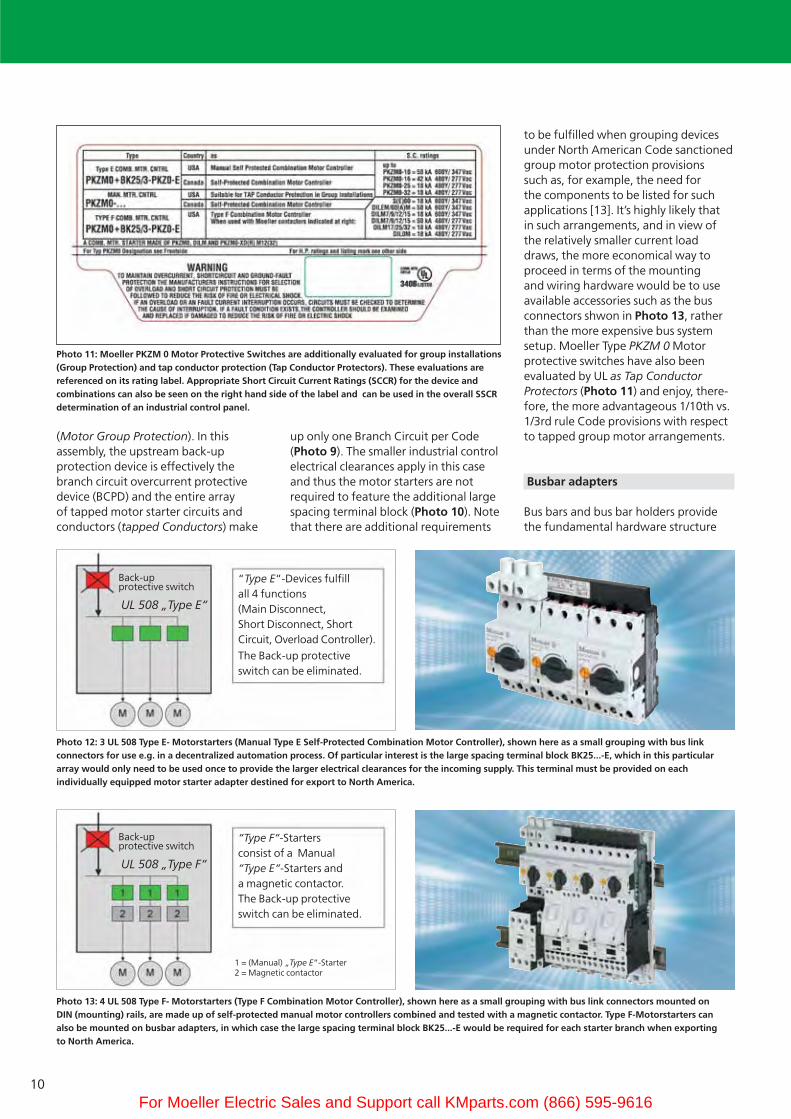
to be fulfilled when grouping devicesunder North American Code sanctionedgroup motor protection provisionssuch as, for example, the need forthe components to be listed for suchapplications [13]. It’s highly likely thatin such arrangements, and in view ofthe relatively smaller current loaddraws, the more economical way toproceed in terms of the mounting and wiring hardware would be to useavailable accessories such as the busconnectors shwon in Photo 13, ratherthan the more expensive bus systemsetup. Moeller Type PKZM 0 Motor protective switches have also been evaluated by UL as Tap Conductor Protectors (Photo 11) and enjoy, there-fore, the more advantageous 1/10th vs.1/3rd rule Code provisions with respectto tapped group motor arrangements.
Busbar adapters
Bus bars and bus bar holders providethe fundamental hardware structure
Photo 11: Moeller PKZM 0 Motor Protective Switches are additionally evaluated for group installations(Group Protection) and tap conductor protection (Tap Conductor Protectors). These evaluations arereferenced on its rating label. Appropriate Short Circuit Current Ratings (SCCR) for the device andcombinations can also be seen on the right hand side of the label and can be used in the overall SSCRdetermination of an industrial control panel.
Photo 12: 3 UL 508 Type E- Motorstarters (Manual Type E Self-Protected Combination Motor Controller), shown here as a small grouping with bus link connectors for use e.g. in a decentralized automation process. Of particular interest is the large spacing terminal block BK25...-E, which in this particular array would only need to be used once to provide the larger electrical clearances for the incoming supply. This terminal must be provided on each individually equipped motor starter adapter destined for export to North America.
Photo 13: 4 UL 508 Type F- Motorstarters (Type F Combination Motor Controller), shown here as a small grouping with bus link connectors mounted on DIN (mounting) rails, are made up of self-protected manual motor controllers combined and tested with a magnetic contactor. Type F-Motorstarters can also be mounted on busbar adapters, in which case the large spacing terminal block BK25...-E would be required for each starter branch when exporting to North America.
UL 508 „Type E“
UL 508 „Type F“
“Type E“-Devices fulfill all 4 functions(Main Disconnect, Short Disconnect, ShortCircuit, Overload Controller).
The Back-up protectiveswitch can be eliminated.
“Type F“-Starters consist of a Manual “Type E“-Starters anda magnetic contactor.The Back-up protectiveswitch can be eliminated.
Back-up protective switch
Back-up protective switch
1 = (Manual) „Type E“-Starter2 = Magnetic contactor
For Moeller Electric Sales and Support call KMparts.com (866) 595-9616

11
Busbar adapters, 3-pole, for bus systems with 60 mm phase to phase bus separationfor 5 mm or 10 mm bus thickness
For Direct-on-Line Starters For Motor Protective Switch General Usage
Screw type terminations Cage clamp Screw type terminations
Ie 25 A 32 A 63 A 63 A 16 A 63 A 63 A 25 A
Ue 690 V 690 V 690 V 690 V 690 V 690 V 690 V 690 V
Conductors AWG 12 AWG 10 AWG 8 AWG 8 AWG 14 AWG 8 AWG 8 AWG 12
~ 4 mm2 ~ 6 mm2 ~ 10 mm2 ~ 10 mm2 ~ 2.5 mm2 ~ 10 mm2 ~ 10 mm2 ~ 4 mm2
Application per UL 508A UL 508A UL 508A UL 508A UL 508A UL 508A UL 508A UL 508A
Width 45 mm 45 mm 55 mm 72 mm 45 mm 54 mm 72 mm 45 mm
Length 200 mm 200 mm 260 mm 260 mm 200 mm 200 mm 200 mm 200 mm
Busses 1 2 2 2 2 1 1 2
for PKZM0 PKZM0 PKZM4 PKZ2 PKZM0-C PKZM4 PKZ2 General Usage
Type BBA0-25 BBA0-32 BBA4L-63 BBA2L-63 BBA0C-16 BBA4-63 BBA2-63 BBA0-25 /2TS
Combinaed with
DILM7 • • DILMC7
DILM9 • • DILMC9
DILM12 • • DILMC12
DILM15 • •DILM17 • • •DILM25 • • •DILM32 • • •DILM40 • •DILM50 • •DILM65 • •
MSC-D-0,25-M7 bisMSC-D-16-M15
•
MSC-D-16-M17 bisMSC-D-32-M32
•
Table 4: Busbar adpaters for Direct-on-Line starters, individual Motor Protective Switches or general usage, with one or two mounting rails
For Moeller Electric Sales and Support call KMparts.com (866) 595-9616

12
Busbar adapters, 3-pole, for bus systems with 60 mm phase to phase bus separationfor 5 mm or 10 mm bus thickness
For Reversing Starters Empty adapter
without
electrical connectorsScrew type terminations Cage clamp
Ie 25 A 32 A 16 A
Ue 690 V 690 V 690 V 690 V 690 V
Supply conductors AWG 12 AWG 10 AWG 14 - -
~ 4 mm2 ~ 6 mm2 ~ 2.5 mm2 - -
Application per UL 508A UL 508A UL 508A UL 508A UL 508A
Width 90 mm 90 mm 90 mm 45 mm 54 mm
Length 200 mm 200 mm 200 mm 200 mm 200 mm
Mounting rails 1 2 2 2 2
for PKZM0 PKZM0 PKZM0-C General usage General usage
Type BBA0R-25 BBA0R-32 BBA0RC-16 BBA0/2TS-L BBA4/2TS-L
Combined with:
2 x DILM7-01 • 2 x DILMC7-01
2 x DILM9-01 • 2 x DILMC9-01
2 x DILM12-01 • 2 x DILMC12-01
2 x DILM17-01 •2 x DILM25-01 •2 x DILM32-01 •
MSC-R-0,25-M7 bisMSC-R-12-M12 •
MSC-R-16-M17 bisMSC-R-32-M32 •
Table 5: Busbar adapters for Reversing starters or empty modules without any electrical connectors, with one or two mounting rails
For Moeller Electric Sales and Support call KMparts.com (866) 595-9616

13
Busbar adapters, 3-pole, for bus systems with 60 mm phase to phase bus separationfor 5 mm or 10 mm bus thickness
For circuit breakers, Switch Disconnectors, Molded Case Switches
Ie 160 A 250 A 550 A
Ue 690 V 690 V 690 V
Supply conductors Integrated flexibus Taking advantage of the device’s rear connection capability
Applications per UL 508A UL 508A UL 508A
Width 90 mm 106 mm 140 mm
Length 200 mm 190 mm 270 mm
Type NZM1-XAD160 NZM2-XAD250 NZM3-XAD550
Combined with:
NZM 1 •PN1 (IEC-Version) •N1 (IEC-Version) •NS1 •
NZM 2 •PN2 (IEC-Version) •N2 (IEC-Version) •NS2 •
NZM3 •PN3 (IEC-Version) •N3 (IEC-Version) •(NS3) in Arbeit •
Rear connection neccessary
- + +
Table 6: Busbar adapters for Circuit Breakers, Switch-Disconnectors and Molded Case Switches
For Moeller Electric Sales and Support call KMparts.com (866) 595-9616
14
adapters, onto which components aremounted, is what truly completes the modern bus system in its overallfunctionality and makes it ideally suitedfor industrial control panel applications.The adapters provide, in effect, the intelligence behind the system, and the refined aspects of its design offerthe end-user a host of useful and functionality driven features, like theability to make rapid module exchangesin the event of a significant fault in thedownstream portion of the branch circuit, or when last minute updates inthe sizing of motors would necessitatea quick change in the motor startercomponent selection. All such adapters,designed to accommodate advantageous,and fuseless, motor starter combinations,are suitable for world markets since, in addition to the availability of thirdparty approvals, each is equipped withconductors sized to North AmericanAWG8-Cross-sections and provided withappropriately rated insulation thicknessesand ratings common in that market.The motor starter adapters are easilysnapped onto the busbars manually without the use of any tools, and establish a reliable and solid connectionthrough spring loaded fastening clips. Larger adapters, designed to accommodate heavier and larger current carrying components, such asmolded case switches and circuit breakers, come equipped with captiveand integrated fastening screws to further secure the component’s placement and connection with the bussystem. One screw per phase is all thatis necessary to secure a fully reliableelectrical and mechanical bond. Whereas individually mounted motorstarter units are normally fed and connected through the top with flexible wires from the adapter’s incoming supply side, a rear connectioncapability proves to be particularly advantageous for larger load carryingcomponents like circuit breakers. Thistype of connection option provides fora touch safe, and especially compact solution. Accordingly, Tables 4 and 6show the adapters to be available in various widths and current loadingcomponent mounting capabilities. The motor starter adapters, dependingon the type and variety of componentsfor any particular motor starter configuration, are available with either1 or 2 mounting rails. The second rail,
which is extendable, facilitates mounting and wiring of larger startersby allowing the use of specially designedinterconnecting links between the motor protective switch and contactorsof various sizes.
Motor Starters per UL 508 and CSA-C22.2 No. 14 standards
Busbar adapters from the Moeller SASY 60i System described herein are in complete conformity with the morestringent approval requirements in effect for applications in North America.As previously mentioned, the incomingsupply wiring to the motor protectiveswitch consists solely of listed and properly sized conductors with AWGcross-sections. But the necessary requirements go much more beyondthat. The supply side of individuallymounted combination motor starterssuitable for branch circuits resides inthe feeder, and the motor protectiveswitch must thus be listed as a “UL 508 Manual Type E – Self-protectedCombination Motor Controller“ (Photo10) which, when combined with a conventional magnetic motor contactorfor remote operation of the starter, canbe additionally evaluated as a so-called“UL 508 Type F-Combination MotorStarter“ (Photo 13). The alphabeticalType E and Type F descriptions are notMoeller terms but rather a part of aninformative short hand method bywhich the construction types of various
combination motor controller configurations currently available in theNorth American market are identifiedin the UL 508 Industrial Control standard. These latest, and specialized,Combination Motor Starter varieties arecomprehensively described in a Moellertechnical paper [13]. The backgroundbehind the need to create these types isbased on the fact that North Americanstandards do not recognize the inherentcapability of conventional IEC typemanual motor starters to provide boththe overcurrent protective and isolatingfunction for motor branch circuits, as isthe case in IEC dominated markets; assimple manual motor controllers theyare able to fulfill switching and overloadprotective duties only. Type E and Type F-Combination Motor starters, inaddition to undergoing special testingto verify their ability to protect againstshort circuits and to fulfill the main disconnect function to the motor branchcircuit, are equipped with an additionalterminal block on their incoming supplyside to provide the larger distributionelectrical clearances (similar to UL 489products) required for connections inthe feeder circuit. These larger supplyside spacings are also obviously requiredwhen mounting these starters on busbaradapters in approved assemblies. Allcomponents, busbars, adapters and the incoming supply side of the Type Emanual motor protective switch thusfeature the large clearances in order topermit their installation in the feederportion of the circuit.
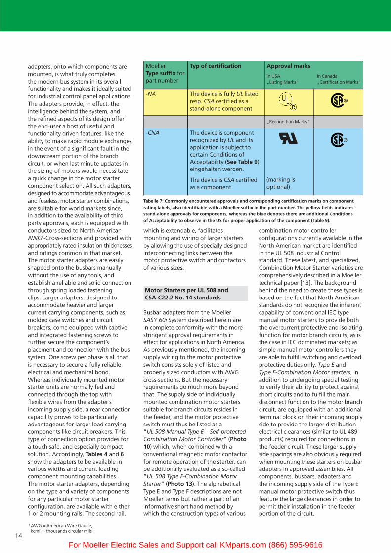
Moeller Type suffix forpart number
Typ of certification Approval marks
in USA in Canada„Listing Marks“ „Certification Marks“
-NA The device is fully UL listedresp. CSA certified as astand-alone component
„Recognition Marks“
-CNA The device is componentrecognized by UL and itsapplication is subject tocertain Conditions ofAcceptability (See Table 9)eingehalten werden.
The device is CSA certifiedas a component
Tabelle 7: Commonly encountered approvals and corresponding certification marks on componentrating labels, also identifiable with a Moeller suffix in the part number. The yellow fields indicatesstand-alone approvals for components, whereas the blue denotes there are additional Conditionsof Acceptability to observe in the US for proper application of the component (Table 9).
(marking isoptional)
®
®
8 AWG = American Wire Gauge, kcmil = thousands circular mils
For Moeller Electric Sales and Support call KMparts.com (866) 595-9616

15
Approval doesn’t always mean approval- Subtle differences, whichalso apply to busbar adapters
In North America, switching and protective devices are subject to thirdparty certification and verification markings. Table 7 describes variousforms of approvals which can be encountered, as well as their significance.The type of approval has an impact onthe requirements of protective andswitching devices and can influencetheir selection, procurement and, ultimately, the manner in which theycan be applied. In this paper the termsapproval and certification are often usedin the same context. The certification isthe official and independently verifedconfirmation, that an evaluated component or assembly has met thatcountry’s application and safety relatedstandards. The afore-mentioned UL andCSA standards are often representative of the country’s officially recognizedstandards amongst international standard making bodies, such as is the case for UL and ANSI9 in the UnitedStates.
Listed Industrial Control Equipment
Without restriction
Recognized Component Industrial Control EquipmentSubject to Conditions of Acceptability
• Devices listed for “field wiring“
• “factory wiring“ is covered by “field wiring“ provisions
i.e.
- Suitable for industrial control panels,and considered complete for field wiring, incl. factories, panel shops and on site.
- Component sale in the US isunrestricted and not subject to anyspecial acceptability considerations,other than they must be applied toper the installation recommendationsof the local electrical Codes.
• As components, devices are subjectto “factory wiring“ provisions
i.e.
- Components must be supplementedwith additional equipment in orderto be properly applied in the endproduct.
- Component selection was conductedby qualified persons in accordancewith application considerations andrelevant acceptability conditions.
- Components are suitable for use inindustrial control panels which aredesigned, assembled and testedby technically qualified personsin appropriate factories and panelshops.
Mark: Mark:
Table 8: In the US, industrial control equipment evaluated per UL 508 can be categorized as “ListedIndustrial Control Equipment“ and “Recognized Component Industrial Control Equipment“.
UL 508 Type F Combination Motor Controllers Suitably listed without contactor as a UL 508 Manual Type E Self-Protected Combination Motor Controller
Maximum HP Ratings3-phase, 60 Hz
Set Current ranges Short CircuitCurrent Rating SCCR
Supply sideterminalblock(alwaysrequired)
MotorProtectiveSwitch
Magnetic-Contactor
208 V (200 V)
240 V (230 V)
480 V 1)
(460 V)600 V 1)
(575 V)Thermal(Adjustable)
Magnetic(Fixed)
200 V240 V480 V1)
600 V1)
HP HP HP HP A A kA kA Type Type Type
Table 9: Short circuit rating of Moeller combination motor starters mounted on busbar adapter. Selection data for the North American market, with individual part numbers shown for field completion of assembly on appropriate bus systems by customers and installers.
BK25/3- PKZM0-0,25 DILM7PKZ0-E PKZM0-0,4 DILM7
PKZM0-0,63 DILM7PKZM0-1 DILM7PKZM0-1,6 DILM7PKZM0-2,5 DILM7PKZM0-4 DILM7PKZM0-6,3 DILM7PKZM0-10 DILM9PKZM0-12 DILM12PKZM0-16 DILM15PKZM0-20 DILM25PKZM0-25 DILM25PKZM0-32 DILM32
BK50/3- PKZM4-16 DILM17PKZ4-E PKZM4-25 DILM25
PKZM4-32 DILM32PKZM4-40 DILM40
0.2 - 0.25 3.4 50 500.3 - 0.4 5.6 50 500.4 - 0.63 8.8 50 50
m m 0.6 - 1 14 50 50o 1 1 - 1.6 22 50 50
m m 1 1m 1.6 - 2.5 35 50 501 1 2 3 2,5 - 4 56 50 50
1m 1m 3 5 4 - 6 88 50 503 3 7m 10 6.3 - 11 140 50 503 3 7m - 8 - 12 168 50 -3 5 10 - 10 - 16 224 50 -5 5 10 - 16 - 20 280 18 -5 7m 15 - 20 - 25 350 18 -
7m 10 20 - 25 - 32 448 18 -
3 5 10 - 10 - 16 224 50 257m 7m 20 - 20 - 25 350 50 2510 10 25 - 25 - 32 448 50 2510 10 30 - 32 - 40 560 50 25
1) Suitable only for use in grounded supply networks rated 480 Y/277 V 60 Hz resp. 600 Y/347 V 60 Hz .
9 ANSI = American National Standards Institute
For Moeller Electric Sales and Support call KMparts.com (866) 595-9616

16
UL 508 Type F Combination Motor Controllers, mounted and wired on busbar adaptersShort Circuit Rating of the combination when mounted on appropriate busbar system
Suitably listed without contactor as a UL 508 Manual Type E Self-Protected Combination Motor Controller
Maximum HP Ratings 3-phase, 60 Hz
Set Current ranges Short Circuit Cur-rent Rating SCCR
Completed busbaradapter
(For IEC-Versions, see notein right side column)
Supply sideterminal block(alwaysrequiredfor UL)
Type: BK25/3 -PKZ0-E
208 V (200 V)
240 V (230 V)
480 V 1)
(460 V)600 V 1)
(575 V)Thermal(Adjustable)
Magnetic(Fixed)
200 V240 V480 V1)
600 V1)
HP HP HP HP A A kA kA Type
Table 10: Short Circuit Rating of combination motor starters mounted on Moeller busbar system. Selection data for the North American market, with partnumbers shown referring to the motor starter equipped and connection ready busbar adapter.
MSC-D-0,25-M7(24VDC)/BBAMSC-D-0,4-M7(24VDC)/BBAMSC-D-0,63-M7(24VDC)/BBAMSC-D-1-M7(24VDC)/BBAMSC-D-1,6-M7(24VDC)/BBAMSC-D-2,5-M7(24VDC)/BBAMSC-D-4-M7(24VDC)/BBAMSC-D-6,3-M7(24VDC)/BBAMSC-D-10-M9(24VDC)/BBAMSC-D-12-M12(24VDC)/BBAMSC-D-16-M17(24VDC)/BBAMSC-D-20-M25(24VDC)/BBAMSC-D-25-M25(24VDC)/BBAMSC-D-32-M32(24VDC)/BBA
0.2 - 0.25 3.4 50 500.3 - 0.4 5.6 50 500.4 - 0.63 8..8 50 50
m m 0.6 - 1 14 50 50o 1 1 - 1.6 22 50 50
m m 1 1m 1.6 - 2.5 35 50 501 1 2 3 2.5 - 4 56 50 50
1m 1m 3 5 4 - 6 88 50 503 3 7m 10 6.3 - 11 140 50 503 3 7m - 8 - 12 168 50 -3 5 10 - 10 - 16 224 50 -5 5 10 - 16 - 20 280 18 -5 7m 15 - 20 - 25 350 18 -
7m 10 20 - 25 - 32 448 18 -1) Suitable only for use in grounded supply networks rated 480 Y/277 V 60 Hz resp. 600 Y/347 V 60 Hz .
In the US, Industrial Control Equipmentper UL 508 [10] as well as equipment for energy distribution (e.g. UL 489 [9])can be encountered with either fullstand-alone certification (e.g. UL Listed)or under the more restrictive recognition category (Recognized Components). Different laboratorymarks apply to both types. Fully Listedequipment (typically denoted by thesuffix “-NA” for certain Moeller components) can be installed with virtually no restrictions, as long as theyare applied within their ratings andcapabilities per the Electrical Codes."Recognized Components" (with Moeller suffix “-CNA“ in their partnumbers) are by themselves consideredincomplete, and often need to be combined with additional componentsin order to be applied properly. These application considerations arealways covered and described in themanufacturer’s certification reportunder the heading “Conditions ofAcceptability” and must always be followed in order to insure full compliance with installation Codes. Based on a UL statistical analysis of rejections encountered in the evaluation of electrical installationsthroughout North America, a large
majority of the issues could be traced to the misuse and misapplication ofdevices with component recognitiononly, which were either improperlycombined with other components, orsimply not applied per their intendedevaluation. As a consequence, approvalauthorities tend to place a greateremphasis on the proper selection and combination of recognized onlycomponents with other devices and elements in the circuit, as well as theneed for their assembly in an enduseproduct to be performed and monitoredin an approved manufacturing location.Approved assembly factories andworkshops are subject to routine andregularly scheduled inspections fromthe approval authorities to monitortheir work and compliance with appropriate standards (Follow-up-Service). The manufacturer’s report andprocedure pages describe in detail whattype of assembly can be performed ineach respective location. Only approvedmanufacturing locations are entitled toapply listing marks to component combinations and assemblies.
In Canada, the approval authoritieshave always paid the same type ofattention to this issue albeit without
the same type of officially publicizeddifferentiation afforded to RecognizedComponents in the US. In a furtherdevelopment to this effect, CSA hasnow begun to introduce a special symbol on components to denote their special, “recognized only” status. A yellow triangle will be placed on products with a known history andtrack record of mis-application in Canada. This will be done in order tobetter alert the approval authorities tothe need of insuring that the product isbeing applied in conformity with localinstallation Codes.
Note: An approval without restriction (e.g. UL-LISTED or CSA-CERTIFIED)in no way implies that these components can be readily used and applied in the same manner as they are in the IEC world. The suitability and functionality of a fully listed product or assembly are established by the approval authorities through the evaluationprocess and are subsequently documented in a report. Apart from the additional restrictions placed on “Recognized Components” as described in Table 8, the validity of a stand-
For Moeller Electric Sales and Support call KMparts.com (866) 595-9616

17
alone listing or certification is onlymeaningful with its relevance to North American installation Codes, and products so listed and certified must be applied accordingly.
Applications for which these devices aresuitable (Energy distribution or controlpanels, motor starters, elevator controlsetc..) and for which required ratingswere obtained and documented in areport, must always be reflected andcovered by the rating labels provided on the product or, when allowed, inaccompanying documentation supplied with the product.
Adapters equipped with motor starters
Moeller offers bus adapters fully equippedfor combination motor starters. Theseadapters are suitable for use in the IECworld as well as in North Americanbranch circuits. When installed withtheir incoming supply in the feeder circuit, these motor starters must be additionally equipped with the aforementioned BK25/3-PKZ0-E largespacing terminal block. Fully equippedadapters, with type suffix „-NA“, will be possible for customer specific NorthAmerican motor starter combinations in large volume. Whereas, generallyspeaking, not much attention is focusedon whose motor protective devices andcontactors end up mounted and wiredon busbar adapters in the IEC world, the situation with respect to NorthAmerican exports is decidedly morecomplicated.
Empty busbar adapters, i.e. thosewithout any components mounted,cannot be listed as stand-alone equipment in North America since theymust be completed in some form oranother in order to be installed andachieve proper functionality in power circuits. Such adapters, therefore, fallunder the Recognized Componentscategory. As previously alluded to, a componentrecognition for these accessories willlikely require them to be combined andtested with specific components, andalso possibly subject them to additionalconditions of acceptability. The entire assembly, along with any such
stipulations, would then be detailed ina manufacturer’s certification report.This would also include a description ofthe busbars, bus holders and any otherrelated hardware, as well as all of the significant power circuit components.Indeed, all vital elements of the busbarsystem, including all motor starterpower circuit components, need to beincluded in overall testing in order toinsure the viability of the entire assembly,particularly under fault conditions. At this point it should become clear to anyone involved in specifying orinstalling such systems that it would be very difficult to obtain written validation of the expected performance,under overload or fault conditions, of components which were obtainedfrom 2 or 3 different suppliers, and randomly assembled together as a complete unit. A certificate for eachindividual component may be easyenough to secure, but there is a muchlesser likelihood of securing verificationfor a complete assembly, as it properlyshould be the case. Obtaining fullytested bus adapter combinations, suchas those from Moeller, would be thesafest, and most advantageous, way togo, since a certification report for thecomplete assembly would be readilyavailable. That in itself is already a lotmore than just simply taking advantageof the mounting and wiring features ofa busbar and bus adapter based system.That is especially the case today forassemblies in compliance with the industrial control panel standard UL 508A, which mandates the establishment of an overall Short Circuit Current Rating based on theSCCRs of all power circuit componentsincluded in the assembly.
In terms of component ratings, it makesabsolutely no difference in Moeller equipment whether the electrical connections between the motor protective switch and the associatedcontactor are made with specially designed, pre-fabricated connectors(e.g. Type PKZM0-XM32DE), or with adirect plug-in connection design, whichis considered just as technologicallymodern and comfortable in terms of installation. All Moeller combinationsare tested together and evaluated withthe bus system as an assembly, and theresults are summarized and tabulated in the certification report. In addition,
the rating labels of each motor protectiveswitch are marked to indicate therespective contactors with which theywere tested as a combination. In NorthAmerica, a great deal of work is requiredon the part of manufacturers withrespect to the description of permissiblecomponent combinations which can be applied. As long as there is strictadherence to the overall assemblies thathave been comprehensively described ina manufacturer’s certification, and theirassociated ratings, the panel builder isfree to combine the components on his own as best suits the application(Table 9). If the panel in question ismeant to be suitable for world markets,then it would be necessary to equip the motor starter adapters, fed directlyfrom a feeder circuit, with the additionallarge spacings terminal accessory (Table10). Type E und Type F-Combinationmotor starters in North America arerated for grounded wye type distributionnetworks. Consult the Moeller catalogfor appropriate frame sizes and nominalcurrent and voltage ratings (e.g.480Y/277 V or 600Y/ 347 V). For IECmarkets only, the use of the additionalspacings terminal on the bus adaptermounted motor starters is not necessary.
Summary
Mounting motor starters and moldedcase circuit breakers on busbar adaptersin industrial control panels is not aswidely practiced in North America as it is in the the IEC world. Nevertheless,machine manufacturers from Europeand overseas are helping to propogatethis modern and effective technology inNorth America through their exports. As a tool to help expand and promotethe concept even further, this paperoutlines the necessary measures whichneed to be undertaken in order for the technology to be in conformitywith pertinent North American safety standards and applicable electrical installation codes.
Smartly designed busbar systems and adapters are not only useful in saving precious mounting and wiring time, but they contribute greatly by defaulttowards a more refined and effectiveuse of space, as well as an overall muchcleaner panel component layout. All thefeatures combine to provide a highly
For Moeller Electric Sales and Support call KMparts.com (866) 595-9616

18
esthetic and modern look while guaran-teeing maximum levels of mechanicalrobustness and electrical safety. Moellercomponents from the Busbar SystemSASY 60i have the necessary features tofulfill all of the essential requirementsfor world market applications, includingthe unique demands of the North American market. Moeller improves onthe efficacy of the system by makingconnection ready motor starter equippedbus adapters available for most applications. It’s much quicker and less error prone to perform essentialmounting and wiring of units in a factory setting rather than on a shopfloor, or worse, at the installation site.Of particular importance is the certification report, in which all of thesystem elements are properly described,and which makes it much easier to accurately determine the short circuitrating (SCCR) of the overall controlpanel. The availability of such a reportgreatly facilitates the entire approvalprocess of the assembly in North America.The provision of an overall short circuitrating (SCCR) on the nameplate of control panels for industrial machinery(Control Panels for Industrial Machinery),indeed all control panels, became arequirement of UL 508A in April of2006. [8]. Similarly, Article 409 of theNEC mandates Short Circuit CurrentRatings (SCCR) for all industrial controlpanels since the beginning of 2005. This additional, and broad reaching, requirement has certainly caused itsshare of major headaches amongstpanel builders throughout the industry.The advent in the market of connectionready, and short circuit rated, componentequipped busbar adapters falls exactlyin line with this concept, and shouldmake the ones available from Moellerthat much more attractive to the panelbuilder. In particular, the short circuitlevels achieved for the Moeller units canbe categorized in the “very high fault”category, which will not be the casewith unevaluated assemblies made upof individual components, the maximumratings of which could be capped atrelatively low levels of short circuit current ratings. (The UL 508A standardhas a provision to assign values forunevaluated and unmarked componentson average in the range of 5kA to 10kA,depending on the component.)Fully equipped adapters with customerspecific combinations in larger volumes
can be made available. For North American installations, Type E or Type Fcombination motor controllers must be fitted with a distribution spacing terminal block on their incoming supplyside. The mounting of molded case circuit breakers and switches up to 550 Ashould be of particular technical, as well as economical, interest. Apart fromthe components presented herein, theMoeller busbar system SASY 60i alsoencompasses provisions for bus mountedIEC fuse assemblies, as well as NorthAmerican fuses. New, additional rationalization potentials are on tapfeaturing simple networking (eliminatingcontrol circuit wiring) using MoellerSystem Smart Wire technology.
Bibliography:
[1] IEC 60 439-1, DIN EN 60 439-1,VDE 0660 Part 500: 2000-08,“Low-voltage switchgear andcontrolgear assemblies - Part 1:Type-tested and partially type-tested assemblies”.VDE-Verlag, Berlin-Offenburg
[2] IEC / EN 60204-1 and DIN EN60204-1 * Classification VDE 0113Part 1 “Safety of machinery - Electrical equipment of machines -Part 1: General requirements”(1992, 1993) and IEC 204-1 Draft 9/2002
[3] NFPA 79, Electrical Standard forIndustrial Machinery, 2002 EditionCopyright: National Fire Pretection Association
[4] Wolfgang Esser,„Kommunikation bei Leistungs-schaltern immer wichtiger“Elektropraktiker, Berlin 57 (2003) 1,Sonderdruck VER 1230-930, Moeller GmbH, Bonn
[5] Wolfgang Esser,“xStart – The New Generation:100 Years of Moeller contactors –Continuous Progress!“, VER 2100-937GB, Moeller GmbH, Bonn, 2004
[6] UL 508A, “Standard for IndustrialControl Panels, September 1, 2005ISBN 0-7629-0398-8Copyright: Underwriters Laboratories INC.
[7] Wolfgang Esser“Xstart – Modern Switching Installations Efficiently Fitted, and Wired Securely“VER 2100-938GB Moeller GmbH, Bonn, 2004
[8] Wolfgang Esser“SCCR – overall Short Circuit Current Rating per NEC and UL standards- a distinguishing feature of North American Industrial Control Panels-”Moeller GmbH, Bonn, 2006VER1200+2100-953Download: http://www.moeller
[9] UL 489, “Molded Case Circuit Breakers,Molded Case Switches and CircuitBreaker Enclosures“,dated June 30, 2006 ISBN 0-7629-0677-4Copyright: Underwriters Laboratories INC.
[10] UL 508, “Industrial Control Equipment”,1999, July 11, 2005ISBN 0-7629-0404-6Copyright: Underwriters Laboratories INC.
[11] UL 67 “Standard for Panelboards,redaction 1993-12-08, Revision 2006-04-12“,Copyright: Underwriters Laboratories INC.
[12] UL 891 “Switchboards”, dated July 26, 2005ISBN 0-7629-1056-9Copyright: Underwriters Laboratories INC.
[13] Wolfgang Esser“Special considerations governingthe application of Manual MotorControllers and Motor Starters inNorth America”Moeller GmbH, Bonn, 2004VER1210-1280-928GB, Article No.: 267952Download:http://www.moeller.net/binary/ver_techpapers/ver_motorstarter-na_de.pdf
[14] Moeller Solution 14easyConnect SmartWireConnecting Instead of Wiring KM0213-4287GBArticle No.: 108784Download:http://www.moeller.net/binary/automatisierung/ms14en.pdf
For Moeller Electric Sales and Support call KMparts.com (866) 595-9616

19
• Conventional wiring
Motor starters from standard components
+ Tool-less plug connector+ SmartWire
+ Busbar adapter
+ Tool-less plug connector+ SmartWire
+ Three-phasecommoning link
+ Tool-less plug connector
+ SmartWire
• Saving space and maincircuit wiring
• Saving control circuitwiring and PLC I/O
• Saving space and main circuit wiring• Saving control circuit wiring and PLC I/O• Saving power supply wiring
+ Tool-less plug connector
• Saving spaceand main circuitwiring
The System Module for Your Individual Solution
Machine builders, panel builders and electricians are able to use SmartWirestraightaway since the SmartWire system is an addition to the established Moellerrange. For example, the SmartWire module for DILM is plug fitted simply like anauxiliary contact onto contactors up to 32 A. The motor-protective circuit-breakerfrom the standard range is added to create a motor starter. This combination cannow be fitted directly to a top-hat rail, extended with a three-phase commoninglink or mounted on a busbar adapter. The system accessories for contactors andmotor-protective circuit-breakers can still be used. For example, the space-savingSmartWire module for DILM can be used to create motor starters up to 15 kW.
For Moeller Electric Sales and Support call KMparts.com (866) 595-9616

Xtra Combinations
Xtra Combinations from Moeller offers a range of productsand services, enabling the best possible combination optionsfor switching, protection and control in power distributionand automation.
Using Xtra Combinations enables you to find more efficientsolutions for your tasks while optimising the economic viability of your machines and systems.
It provides:■ flexibility and simplicity■ great system availability■ the highest level of safety
All the products can be easily combined with one another mechanically, electrically and digitally, enabling you to arriveat flexible and stylish solutions tailored to your application –quickly, efficiently and cost-effectively. The products are proven and of such excellent quality thatthey ensure a high level of operational continuity, allowingyou to achieve optimum safety for your personnel, machinery,installations and buildings.
Thanks to our state-of-the-art logistics operation, our com-prehensive dealer network and our highly motivated servicepersonnel in 80 countries around the world, you can count on Moeller and our products every time. Challenge us! We are looking forward to it!
Moeller addresses worldwide:www.moeller.net/address
E-Mail: [email protected]: www.moeller.net
Issued by Moeller GmbHHein-Moeller-Str. 7-11D-53115 Bonn
© 2007 by Moeller GmbHSubject to alterationsVER4300-960GB MDS/?? 02/07 Printed in Germany (03/07)Article No.: 110775
For Moeller Electric Sales and Support call KMparts.com (866) 595-9616