BUS - belimo.ch VAV_en.pdf · the sensor materials is to be tested (see Technical data VFP-.. and...
36
www.belimo.eu S4-VRP-M VAV • en • v4.2 • 06.2016 • Subject to changes 1 / 36 Product information System VRP-M VAV MP BUS ® TECHNOLOGY BY BELIMO Adaptive VAV control system for sensitive working areas Table of contents Overview of the system 2 System description 3 Technical data sheets Adaptive VRP-M digital PID volumetric flow controller 5 Application 6 Functions 10 System configuration 13 Operating data settings (with VRP-M-Tool) 14 PC-Tool connection 16 Service-Tool ZTH-GEN 18 Bus operation 20 VFP-.. static pressure value sensors for neutral to slightly aggressive gases 23 VFD3 dynamic pressure value sensor for room ventilation applications 25 Fast-running damper actuator for VRP-M system solution LMQ24A-SRV-ST 27 Fast-running damper actuator for VRP-M system solution NMQ24A-SRV-ST 29 Damper actuator for VRP-M system solution NM24A-V-ST 31 Spring-return actuator with emergency setting function for VAV and CAV units SF24A-V-ST 33 Dimensions 35
Transcript of BUS - belimo.ch VAV_en.pdf · the sensor materials is to be tested (see Technical data VFP-.. and...

www.belimo.eu S4-VRP-M VAV • en • v4.2 • 06.2016 • Subject to changes 1 / 36
Product information System VRP-M VAV
MP BUS®
TECHNOLOGY BY BELIMO
Adaptive VAV control system for sensitive working areas
Table of contents
Overview of the system 2
System description 3
Technical data sheetsAdaptive VRP-M digital PID volumetric flow controller 5
Application 6Functions 10System configuration 13Operating data settings (with VRP-M-Tool) 14PC-Tool connection 16Service-Tool ZTH-GEN 18Bus operation 20
VFP-.. static pressure value sensors for neutral to slightly aggressive gases 23VFD3 dynamic pressure value sensor for room ventilation applications 25Fast-running damper actuator for VRP-M system solution LMQ24A-SRV-ST 27Fast-running damper actuator for VRP-M system solution NMQ24A-SRV-ST 29Damper actuator for VRP-M system solution NM24A-V-ST 31Spring-return actuator with emergency setting function for VAV and CAV units SF24A-V-ST 33
Dimensions 35

VRP-M VAV Overview of the system
2 / 36 S4-VRP-M VAV • en • v4.2 • 06.2016 • Subject to changes www.belimo.eu
Application VAV / CAV STP (pressure)
∆pw w
+ –
∆pw w
+ –
Supply/exhaust air systems ●Extraction systems ●Duct/section pressure ●Actuator variants Standard actuator or fast runner
Spring-return actuator with emergency position OPEN or CLOSED (see Damper actuators)
Sensor variants static or dynamic (see Pressure sensors)Optimiser function for energy-efficient fan control ● 1)
Stage control ●Modulating control ●Local override functions CLOSED / min / mid / max /
OPENCLOSED / Pmin / Pmax / Motor stop
/ OPENBus integration MP bus (MP partner systems), LONWORKS, KNX, Modbus, BACnet,
COU24-A-MP
1 Controller platformVRP-M
VAV / CAV STPSupply AC/DC 24 V
Reference variable control 0 / 2 ... 10 V, 0 / 4 ... 20 mAFeedback, actual value Volumetric flow 0 / 2 ... 10 V ∆p 0 / 2 ... 10 VTools PC-Tool VRP-M module, Service-Tool ZTH-GENOptimiser-compatible ●Suitable gateways UK24LON, UK24EIB, UK24MOD, UK24BACSuitable MP-masters DDC systems from Belimo MP partners, COU24-A-MP
2 Pressure sensors
VFP-100 VFP-300 VFP-600 VFD3Measuring principle static static static dynamicPressure range 0 ... 100 Pa 0 ... 300 Pa 0 ... 600 Pa selectable 0 ...
100 / 300 / 600 Pa 5)
Comfort zone ●Dusty air Dusty to very dusty 2) dusty 2)
Corrosive media Corrosive air 3) 4)
Connection Integrated cable/plug unit, suitable for VRP-M
3 Damper actuators
NM24A-V-ST LMQ24A-SRV-ST NMQ24A-SRV-ST SF24A-V-STFunction Standard Fast runners Fast runners Spring-returnTorque 10 Nm 4 Nm 8 Nm 20 NmRunning time 110 ... 150 s 2.5 s 4 s 150 sEmergency function OPEN or CLOSEDConnection Integrated cable/plug unit, suitable for VRP-M
1) Limitation: Optimiser function requires actuator with standard running time, fast runners are not permitted.2) Independent of the sensor type, the pick-up device (unit component) must be tested at cyclical intervals and
be cleaned as needed.3) The VAV unit (pick-up device, etc.) must be selected in accordance with the medium. The compatibility of
the sensor materials is to be tested (see Technical data VFP-.. and VFD3).4) Compatible with duct cleaning agent and duct disinfecting agent.5) Differential pressure measurement up to 500 Pa.
12
3
12
3
. . . . . .
. . . . . .
www.belimo.eu S4-VRP-M VAV • en • v4.2 • 06.2016 • Subject to changes 3 / 36
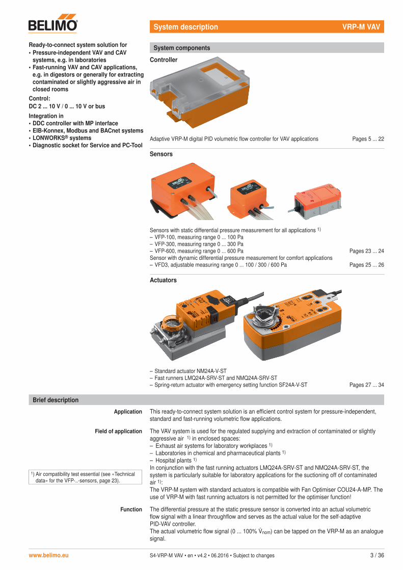
Ready-to-connect system solution for• Pressure-independent VAV and CAV
systems, e.g. in laboratories• Fast-running VAV and CAV applications,
e.g. in digestors or generally for extracting contaminated or slightly aggressive air in closed rooms
Control:DC 2 ... 10 V / 0 ... 10 V or busIntegration in• DDC controller with MP interface• EIB-Konnex, Modbus and BACnet systems• LONWORKS® systems• Diagnostic socket for Service and PC-Tool
Brief description
Application This ready-to-connect system solution is an efficient control system for pressure-independent, standard and fast-running volumetric flow applications.
Field of application The VAV system is used for the regulated supplying and extraction of contaminated or slightly aggressive air 1) in enclosed spaces:– Exhaust air systems for laboratory workplaces 1)
– Laboratories in chemical and pharmaceutical plants 1)
– Hospital plants 1)
In conjunction with the fast running actuators LMQ24A-SRV-ST and NMQ24A-SRV-ST, the system is particularly suitable for laboratory applications for the suctioning off of contaminated air 1):The VRP-M system with standard actuators is compatible with Fan Optimiser COU24-A-MP. The use of VRP-M with fast running actuators is not permitted for the optimiser function!
Function The differential pressure at the static pressure sensor is converted into an actual volumetric flow signal with a linear throughflow and serves as the actual value for the self-adaptive PID-VAV controller.The actual volumetric flow signal (0 ... 100% nom) can be tapped on the VRP-M as an analogue signal.
System components
Adaptive VRP-M digital PID volumetric flow controller for VAV applications Pages 5 ... 22
Sensors
Sensors with static differential pressure measurement for all applications 1)
– VFP-100, measuring range 0 ... 100 Pa– VFP-300, measuring range 0 ... 300 Pa– VFP-600, measuring range 0 ... 600 PaSensor with dynamic differential pressure measurement for comfort applications– VFD3, adjustable measuring range 0 ... 100 / 300 / 600 Pa
Pages 23 ... 24
Pages 25 ... 26
Actuators
– Standard actuator NM24A-V-ST– Fast runners LMQ24A-SRV-ST and NMQ24A-SRV-ST– Spring-return actuator with emergency setting function SF24A-V-ST Pages 27 ... 34
Controller
System description VRP-M VAV
1) Air compatibility test essential (see «Technical data» for the VFP-..-sensors, page 23).

4 / 36 S4-VRP-M VAV • en • v4.2 • 06.2016 • Subject to changes www.belimo.eu
Safety notes
!• The VRP-M system solution is not allowed to be used outside the specified field of
application, especially in aircraft or in any other airborne means of transport.• Only components explicitly approved for this purpose by Belimo are allowed to be used for
the VRP-M system solution.• The equipment configuration and settings form part of the unit manufacturer's system
solution (OEM) and are not allowed to be modified without the OEM's prior authorisation. All changes are liable to disrupt operation and cause damage to the system or injury to persons!
• Attention must be paid to the following during the planning phase and before the VRP-M system solution is operated:– The compatibility of the pressure sensors with the medium to be controlled must be tested,– The specifications supplied by the damper manufacturer (design, place of installation)
must be consulted and– The local technical regulations must be observed.
• Applications with fast running actuator LMQ24A-SRV-ST or NMQ24A-SRV-ST: The actuator moves first to the top, then to the bottom spindle end stops when the supply voltage is switched on for the first time or after pressing the «Adaption» push-button. It then moves into the position required by the system. The VRP-M control function is inoperative during this procedure.
• If the VRP_M solution is operated in a bus system, the cycle times of the MP bus and the higher-level system must be taken into account.
• The damper manufacturer (OEM) is responsible for ensuring that the VRP-M-system solution is installed and set correctly as well as for overall precision. If replacement devices are ordered, they are configured by the OEM at the factory according to the installed system. The VRP-M system solution is sold exclusively via the OEM channel for this reason.
System characteristics
Control characteristics Adaptive, digital PID VAV controller (see «System components», page 3).
Pressure measurement Belimo pressure sensors (see «System components», page 3).
Damper actuators Belimo VAV damper actuators (see «System components», page 3).
Optimally matched components In addition to standardised VAV and CAV applications, the VRP-M system solution is also suitable for fast running applications such as those required in laboratories. The solution comprises the components optimally matched with one another that are therefore only permitted to be used in the controller-sensor-actuator combinations specified by Belimo and selected by the unit manufacturer (see «System components», page 3).
VAV – variable volumetric flow Variable air volume applications based on a modulating reference variable, e.g. supplied by a DDC controller, room temperature controller or bus operation,The reference signal for the min ... max operating range can be set as follows:DC 0 ... 10 V / DC 2 ... 10 V or bus operation
CAV – constant volumetric flow Constant air volume applications with operating modes: CLOSED / min / mid / max / OPEN (bus operation)
Bus function Up to eight Belimo MP devices (VRP-M / VAV-Compact / damper actuator / valve) can be connected via the MP bus and integrated into the following systems:– DDC controller with integrated MP bus protocol– EIB Konnex system with Gateway UK24EIB– LONWORKS® system with Gateway UK24LON– Modbus system with Gateway UK24MOD– BACnet system with Gateway UK24BACSee «Bus system», pages 20 to 22.The VRP-M system with standard actuators is compatible with Fan Optimiser COU24-A-MP. See System documentation COU24-A-MP.
Diagnostics tool PC-Tool VRP-M module, ZTH-GEN, can be plugged into the VRP-M or via external cable connection.
VRP-M VAV System description
Brief description (continued)
The actual value x is compared with the setpoint w set on the VAV controller and the connected damper actuator is connected according to the resulting control deviation. The VRP-M controller can be controlled according to its application as a CAV constant controller (min / max) or a VAV controller via the reference value input w with a modulating 0 … 10 / 2 … 10 V signal in the range from min … max. Control inputs with OPEN/CLOSE/mid functions are available for special applications.The VRP-M can be integrated into an MP system via the MP bus connection.
LimitationThe use of VRP-M with fast running actuators is not permitted for the optimiser function!

www.belimo.eu S4-VRP-M VAV • en • v4.2 • 06.2016 • Subject to changes 5 / 36
Adaptive digital PID volumetric flow controller for VRP-M system solutions• For pressure-independent VAV and
CAV systems• Control: 0 ... 10 / 2 ... 10 V or MP bus• Diagnostic socket for Service or PC-Tool
Technical data
Electrical data Nominal voltage AC 24 V, 50/60 HzDC 24 V
Nominal voltage range AC ±20% / DC ±10%Power consumption Operation
Dimensioning1.1 W (incl. Sensor VF.., without damper actuator)2.6 VA (incl. Sensor VF.., without damper actuator)
Connection ActuatorPressure sensorTerminals 1 ... 7VRP-M-Tool
Plug, 6-pinPlug, 4-pin7-pin screw terminals, 0.5 mm2 ... 1.5 mm2
Plug, 3-pin
Functional data Reference signal w (terminal 3)Range: min ... max
Input impedance >200 k�– DC 0 ... 10 / 2 ... 10 V or– 0 ... 20 / 4 ... 20 mA (with 500 � resistance)
Actual value, volumetric flow U5 (terminal 5)Range 0 ... 100% nom
DC 0 ... 10 / 2 ... 10 V, max. 5 mA
OPEN operating mode – z1 (terminal 6) OPEN, input impedance >300 k�CAV operating modes z2 (terminal 7) CLOSED / min / mid / max
Contact current <1 mAControl characteristics PID, adaptiveControl tolerance ±5% of nom
Ranges nommaxmin 1)
mid (intermediate position) 2)
Nominal volumetric flow (manufacturer-dependent)30 ... 100% of nom0 ... 100% of nom0 ... 100% of min ... max
LED display AC/DC 24 V supplyPressure too high/too low, zero VFP-..sensor
MP bus function (terminal 4) 3)
Address in bus operationFunctionality
MP 1 ... 8 (classic operation: PP)Adjustable with VRP-M-Tool and address push-buttonSlave
Operation / service VRP-M-Tool
Safety Protection class III Safety extra-low voltageDegree of protection IP42EMC CE according to 2004/108/ECPrinciple of operation Type 1 (EN 60730-1)Ambient temperature 0 ... +50°CNon-operating temperature –20 ... +80°CAmbient humidity 5 ... 95% r.h., non-condensing (EN 60730-1)Maintenance Maintenance-free
Dimensions / Weight Dimensions See «Dimensions» on page 35Weight Approx. 250 g (without sensor)
1) See «Creep flow limitation and minimum setting limit», page 102) Not available with DC 24 V supply3) See «Bus operation», pages 20 to 22
Technical data sheet VRP-M

6 / 36 S4-VRP-M VAV • en • v4.2 • 06.2016 • Subject to changes www.belimo.eu
Electrical connections
Front panel
Assignment of connecting terminals 1 ... 7
Safety notes
!• The controller is not allowed to be used outside the specified field of application, especially
not in aircraft or in any other airborne means of transport.• The device does not contain any parts that can be replaced or repaired by the user.• The manufacturer of the unit (OEM) is responsible for ensuring that the VRP-M
controller is installed and set correctly as well as for the overall precision of the unit. If replacement devices are ordered, they are configured by the OEM at the factory according to the installed system. The VRP-M controller is sold exclusively via the OEM channel for this reason.
• The device contains electrical and electronic components and must not be disposed of as household refuse. All locally valid regulations and requirements must be observed.
Application
Together with a VFP-.. / VFD3 pressure sensor and a damper actuator, the VRP-M forms a control system for pressure-independent variable (VAV) and constant (CAV) volumetric flow controls.For more information, see «VRP-M system description», pages 3 ... 4
Connecting terminals 1 ... 7Supply and control Tab connection
Damper actuator
Tab connectionPressure sensor
Service/PC-Tool diagnostic socket
AC 24 VDC 24 V
~T
+_
1 2 3 4 5 6 7
T ~+ MPw U5 z1 z2
LED display and address push-button
PWR Green LED LED on:– Supply AC/DC 24 V OK– Device ready for operation
LED off:– Supply failure– Device defective
Flashing – With Set push-button pressed down for MP addressing+ Red LED LED on:
– Volumetric flow > setpoint = damper closes or is closed– Red LED LED on:
– Volumetric flow < setpoint = damper opens or is open�p > 0 Yellow LED Zero offset pressure sensor VFP-..
(for procedure, see page 9)Set Push-button for assigning the MP address in bus operation
(for procedure, see page 22)
VAV reference signal min ... max
PP/MP communicationVolumetric flow actual value 0 ... 100% nom
OPEN operating modeCAV CLOSED operating mode / min / mid / max
VRP-M Adaptive volumetric flow controller

www.belimo.eu S4-VRP-M VAV • en • v4.2 • 06.2016 • Subject to changes 7 / 36
Electrical installation
Wiring diagrams: VAV operation Example 1:With analogue reference signal
Example 2:DC 0 ... 10 V with shut-off (CLOSED)
Conventional operation:Functional description such as control priority
See pages 11 ... 12
AC 24 V DC 24 V
~ T
+ _
T
4 3 2 1 VRP-M MP w
~ T
+ _ 5 6 7 U5 z1 z2
VFP-..LM.. / NM.. / SF..VRP-M
Tool
4 3 2 1 VRP-M MP w
~ T
+ _ 5 6 7 U5 z1 z2
VFP-..LM.. / NM.. / SF..VRP-M
Tool
+ DC 24 V _
AC 24 V DC 24 V
~ T
+ _
T
Example 3:DC 0 ... 10 V with shut-off / parallel control
4 3 2 1 VRP-M MP w
~ T
+ _ 5 6 7 U5 z1 z2
VFP-..LM.. / NM.. / SF..VRP-M
Tool
+ DC 24 V _
AC 24 V DC 24 V
~ T
+ _
4 3 2 1 VRP-M MP w
~ T
+ _ 5 6 7 U5 z1 z2
VFP-..LM.. / NM.. / SF..VRP-M
Tool
+ DC 24 V _
T
Example 4:With bus control
Example 5:Typical application: MP with shut-off (CLOSED)
Bus operation:See pages 18 to 20 for a functional description
MP
~ T
+ _ AC 24 V DC 24 V
4 3 2 1 VRP-M MP w
~ T
+ _ 5 6 7 U5 z1 z2
VFP-..LM.. / NM.. / SF..VRP-M
Tool
MP
~ T
+ _ AC 24 V DC 24 V
4 3 2 1 VRP-M MP w
~ T
+ _ 5 6 7 U5 z1 z2
VFP-..LM.. / NM.. / SF..VRP-M
Tool
Reference value input w0 ... 10 / 2 ... 10 / adjustable
PP/MP communication
CLOSED (shut-off)
CLOSED (shut-off)
CLOSED (shut-off)
Reference value input w0 ... 10
Notes– Supply via safety isolating transformer!– We recommend routing connections 1, 2
(AC/DC 24 V) and 4 (MP signal) to accessible terminals (floor distributor, control cabinet, etc.), in order to simplify access with the VRP-M-Tool for diagnostic and service work.
!
VRP-M Adaptive volumetric flow controller
Control input z1/z2
PP/MP communication
Actual value volumetric flow U50 ... 10 / 2 ... 10 / adjustable
Actual volumetric flow valueU5 0 ... 10 / 2 … 10 / adjustable
Version overview, Release Note - VRP-M system solution
Up-to-date information about compatibility, versions and functions can be found atwww.belimo.eu
8 / 36 S4-VRP-M VAV • en • v4.2 • 06.2016 • Subject to changes www.belimo.eu
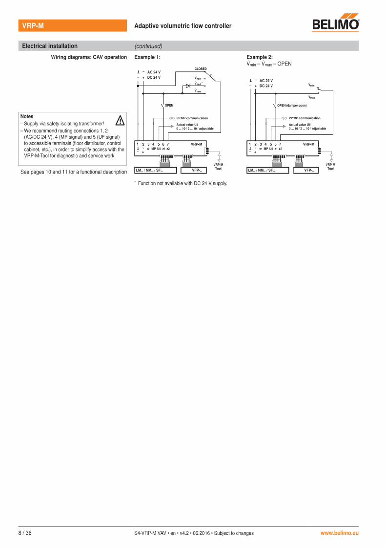
Electrical installation (continued)
Wiring diagrams: CAV operation Example 1: Example 2:min – max – OPEN
See pages 10 and 11 for a functional description
4 3 2 1 VRP-M MP w
~ T
+ _ 5 6 7 U5 z1 z2
VFP-..LM.. / NM.. / SF..VRP-M
Tool
+ DC 24 V _
AC 24 V DC 24 V
~ T
+ _
4 3 2 1 VRP-M MP w
~ T
+ _ 5 6 7 U5 z1 z2
VFP-..LM.. / NM.. / SF..VRP-M
Tool
+ DC 24 V _
AC 24 V DC 24 V
~ T
+ _
* Function not available with DC 24 V supply.
VRP-M Adaptive volumetric flow controller
Notes– Supply via safety isolating transformer!– We recommend routing connections 1, 2
(AC/DC 24 V), 4 (MP signal) and 5 (UF signal) to accessible terminals (floor distributor, control cabinet, etc.), in order to simplify access with the VRP-M-Tool for diagnostic and service work.
!
CLOSED
OPEN
min
max
OPEN (damper open)
mid *
PP/MP communication
Actual value U50 ... 10 / 2 ... 10 / adjustable
PP/MP communication
Actual value U50 ... 10 / 2 ... 10 / adjustable
min
max

www.belimo.eu S4-VRP-M VAV • en • v4.2 • 06.2016 • Subject to changes 9 / 36
Commissioning
Prerequisites The following has been accomplished by the unit manufacturer for the system solution:– The system solution is mounted on the VAV unit– The static pressure sensor has been balanced to the zero point offset or the pressure range of
the dynamic pressure sensor has been adjusted, respectively– The VRP-M has been correctly calibrated and parameterised to the ∆p @ nom value of the
VAV unit– The electrical connection has been made and checked– 24 V supply and control have been made ready for operation– The ventilators have been put into operation
Procedure – Test the electrical connection– Check the zero offset with static pressure sensor or the pressure range setting with dynamic
pressure sensor, respectively– Check the damper mobility– Test the damper angle of rotation setting, correcting it if necessary, and carry out an angle of
rotation adaptation– Check the min / max setting, correcting it if necessary– Test the supply pressure (supply/exhaust air ventilator in operation and balanced)– Test the control signal setting, adjusting it if necessary
Damper actuator angle of rotation adaptation An angle of rotation adaptation is to be performed after each adjustment of the damper angle of rotation limitation, particularly in plants which are operated with a fan optimiser function.In the case of fast runner damper actuators LMQ24A-SRV-ST and NMQ24A-SRV-ST, it is mandatory that a angle of rotation adaptation be carried out after every adjustment of the angle of rotation limitation
Procedure:
– Switch on the 24 V supply– Press the «Adaption» push-button (actuator travels CLOSED … OPEN … setpoint position)
Static pressure sensor VFP-..Zero offset
– Disconnect both (!) hose connections from the sensor– Remove the cover of the sensor housing– Rotate the zero potentiometer inside the VFP-.. until the LED in the VRP-M [p > 0] lights up– Rotate it back until the LED just gets off or
rotate it back until the voltage U5 is <0.04 V / 2.04 V (Mode = 0 ... 10 V / 2 ... 10 V)– Connect the hose connections to the sensor: observe + / – setting!
VFP-100 VFP-300 VFP-600
VRP-M
Dynamic pressure sensor VFD3Pressure range setting
The DIP switches for adjusting the pressure range are located under the VFD3 housing cover.
DIP
DIP switchPosition
Pressure range Remarks
0 ... 100 Pa
0 ... 300 Pa Default setting
0 ... 600 Pa Differential pressure measurement up to 500 Pa
–20 ... 100 Pa
Cannot be used with the VRP-M
If necessary, the setting of the DIP switches can be sealed with a compatible lacquer. It is recommended for purposes of documenting the setting that the selected pressure range be marked on the housing cover with a waterproof felt-tip pen.The VFD3 is not equipped with an external zero adjustment.
NoteFast runner damper actuators LMQ24A-SRV-ST and NMQ24A-SRV-STOnce the push button gear disengagement key is pressed, a synchronisation is carried out, i.e. the actuator moves CLOSED and returns to the setpoint position.
U5
1 5
LED �p > 0Zero potentiometer Zero potentiometer
NoteStatic pressure sensors VFP-..In the event of a mounting orientation that deviates from the perpendicular position, it is mandatory that a zero offset be carried out.
NoteDynamic pressure sensor VFD3The pressure range of the VFD3 is set in the factory by the manufacturer of the VAV unit and configured accordingly in the VRP-M. It is mandatory that an adjustment of the pressure range requires an adaptation in the VRP-M configuration.The pressure range –20 ... 100 Pa cannot be used with the VRP-M.
VRP-M Adaptive volumetric flow controller
. . . . . . . . . . .

10 / 36 S4-VRP-M VAV • en • v4.2 • 06.2016 • Subject to changes www.belimo.eu
VRP-M Adaptive volumetric flow controller
0/2 10 [V]
2
30%
0%
100% 100%
2
1
a
bc
ab
c
1
Functions
Nominal volumetric flow nom nom corresponds to the maximum volumetric flow of the VAV unit at which the pressure drop and noise are still within the permissible operating conditions. The nom values are specified and programmed permanently by the unit manufacturer.The volumetric flow actual value signal U5 is always in reference to the nom. For this reason, changes in the operating volumetric flow setting min and max have no influence on the U5 V signal
Creep flow limitationMinimum setting limit min
Creep flow limitation (1)
This function suppresses differential pressure signals in the zero region. Thanks to this limitation, undefined actuator movements in the effective pressure range of 1 ... 6 Pa are prevented. The operating range is physically limited owing to the dynamic behaviour of the differential pressure sensor in this area and the flow pattern of the fluid being pumped.
Sensor Pressure range LimitationVFP-100 0 ... 100 Pa 1 PaVFP-300 0 ... 300 Pa 3 PaVFP-600 0 ... 600 Pa 6 PaVFD3 0 ... 100 Pa 1 Pa
0 ... 300 Pa 3 Pa0 ... 600 Pa 6 Pa
Unit manufacturer's minimum setting limit (2)
Oversized VAV units can make it harder to regulate the lowermost pressure value range. The manufacturer will specify the lowest permissible volumetric flow for the units, usually corresponding to a pressure value of approximately 5 ... 12 Pa. Functional restrictions in this range can be avoided by complying with the unit manufacturer's volumetric flow adjustment.
Start point
End point
nom
Volumetric flow [nom]
Volumetric flo
w actual va
lue signal U
5 [V]
Setting[min]
Setting[max]
Reference signal w
Optimum rangeSetting with restriction
Setting with greatest restriction
Creep flow limitation <2 Pa
Unit manufacturer's minimum setting limit
0 ... 10 V2 ... 10 Vadjustable

www.belimo.eu S4-VRP-M VAV • en • v4.2 • 06.2016 • Subject to changes 11 / 36
VRP-M Adaptive volumetric flow controller
0,0 10
0,0 0,1 102,0
min
0…10 V
2…10 V
max
max
min
Functions (continued)
Control tolerance The maximum permissible control tolerance is defined as a percentage of the nominal volumetric flow nom. If the control deviation exceeds or undershoots this tolerance, the actuator is adjusted so that the actual volumetric flow corresponds to the required setpoint.Control tolerance: ±5% of nomThe two LEDs [+p] and [-p] will show the following when the maximum control tolerance is exceeded or undershot or when the actuator in movement must be corrected by the deviation:LED [+p]: actual value > (setpoint + control tolerance) = damper closesLED [-p]: actual value < (setpoint + control tolerance) = damper opens
VAV operating volumetric flowSetting min ... max
In variable operation, the pressure is specified by means of the reference signal in the range min ... max.– max forms the upper limit value as a function of the nominal volumetric flow.
Adjustment range 30 ... 100% of nom.– min forms the lower limit value as a function of nom.
Adjustment range 0 ... 100% of nom.
Voltage level
In 2 … 10 V mode, it is possible to achieve shut-off operation (damper CLOSED) by lowering the reference signal to 0.0 V.
For override control in VAV operation, e.g. CLOSED or OPEN, the reference signal w (Input 3) can be overridden by wiring the control inputs 6 (z1) and 7 (z2).
CAV operating modesCLOSED / min / mid / max / OPEN
Five operating modes are available for step mode:– Shut-off operation – Damper CLOSED: The damper is moved into the CLOSED position in a
defined manner.– Operating modes min / mid / max: The VRP-M permanently regulates the selected
volumetric flow.– Flushing operation – damper OPEN: The damper can be opened for maximum ventilation, in
which case volumetric flow control is deactivated!The operating mode control signals are connected to inputs 6 (z1) and 7 (z2). If signals appear at these two inputs simultaneously, input 6 (z1) for the OPEN function takes priority.
Reference signal w[V]
nommax
[min]
Variable operation
Volumetric flow [% nom]
Volumetric flow actual value signal U5 [V]
Exam
ple
with
Mod
e 0
… 1
0 V
< Modulating operation >
< Modulating operation >
Start point End point
Shut-off
[max]
Mode:
CLOSED

12 / 36 S4-VRP-M VAV • en • v4.2 • 06.2016 • Subject to changes www.belimo.eu
VRP-M Adaptive volumetric flow controller
862 4
30 40
100%30 40 50 60 70 80 90
0 10010 20 50 60 70 80 90
41%
10
0
10
2
4
6
8
Functions (continued)
100%30 40 50 60 70 80 90
0 10010 20 30 50 60 70 80 90
43%
40
VAV operation with overrideCLOSED / min / mid / max / OPEN
If necessary, the VAV min ... max range can be overridden by fixed operating modes in VAV applications.The following operating modes are available:– Shut-off operation – Damper CLOSED: The damper is moved into the CLOSED position in a
defined manner.– Operating modes min / mid / max: The VRP-M permanently regulates the selected
volumetric flow.– Flushing operation – damper OPEN: The damper can be opened for maximum ventilation, in
which case volumetric flow control is deactivated!
Priorities for reference value input 3 (w) and control inputs 6 (z1) / 7 (z2)
If several signals appear simultaneously, they are processed according to the following priorities.
Reference signal w[V]
CAV operating mode
OPEN(depending on supply pressure)
nom
max
min
CLOSED
[min]
Volumetric flow [% nom]
[max]
Volumetric flow [% nom]
[max]
CLOSED
OPEN
nommax
[min]
Constant operation
Variable operation
Constant operation
min
Volumetric flow actual value signal U5 [V]
Exam
ple
with
Mod
e 2
… 1
0 V
Notes– min: All inputs (3 / 6 / 7) open.– mid not available with DC 24 V supply.
Terminal Priority Function6 z1 1 OPEN7 z2 2 CLOSED / min / mid / max
3 w 3 min … max
mid
mid
Notemid is not available with DC 24 V supply.

www.belimo.eu S4-VRP-M VAV • en • v4.2 • 06.2016 • Subject to changes 13 / 36
VRP-M Adaptive volumetric flow controller
System configuration
Unit manufacturer's settings The system solution selected by the unit manufacturer is mounted by the latter on the VAV unit and configured according to the system requirements (as stated in the order). This configuration comprises the following settings:
VRP-M-ToolExpert tab
System information
Function Volumetric flow
Sensor The pressure sensor type is specified to enable the pressure range to be adapted.
Actuator The actuator type is specified for the adaptation of the running time characteristics.
Density Density adjustment to the environment.
Height Height above sea level for density calculation.
Control – reference signal w, actual volumetric flow signal U5
The reference signal w and the volumetric flow actual value signal U5 are adapted to the MCR system.Selection DC 0...10 V / DC 2...10 V / adjustable (sequence matching in the 0...10 V range)
Calibration – nom The nom values are specified and permanently programmed by the unit manufacturer.With the setting of the nom, every VRP-M system solution is optimally adapted to the VAV unit used. nom corresponds to the maximum volumetric flow of the VAV unit at which the pressure drop and noise are still within the permissible operating conditions. The nom setting is specified by the unit manufacturer.
Replacement orders If replacement devices are ordered, they must be parameterised beforehand by the OEM at the factory according to the installed system. The VRP-M is sold exclusively via the OEM channel for this reason.
Volumetric flowActual value signal U5
[V]
NoteThe equipment configuration and settings form part of the unit manufacturer's system solution (OEM) and are not allowed to be modified without the OEM's prior authorisation. All changes are liable to disrupt operation and cause damage to the system or injury to persons!
0
10
2
4
6
8
NW...NW...NW100 NW...
Volumetric flow [nom]
nom
SmallestNominal diameter
LargestNominal diameter
OEM unit product range
14 / 36 S4-VRP-M VAV • en • v4.2 • 06.2016 • Subject to changes www.belimo.eu
VRP-M Adaptive volumetric flow controller
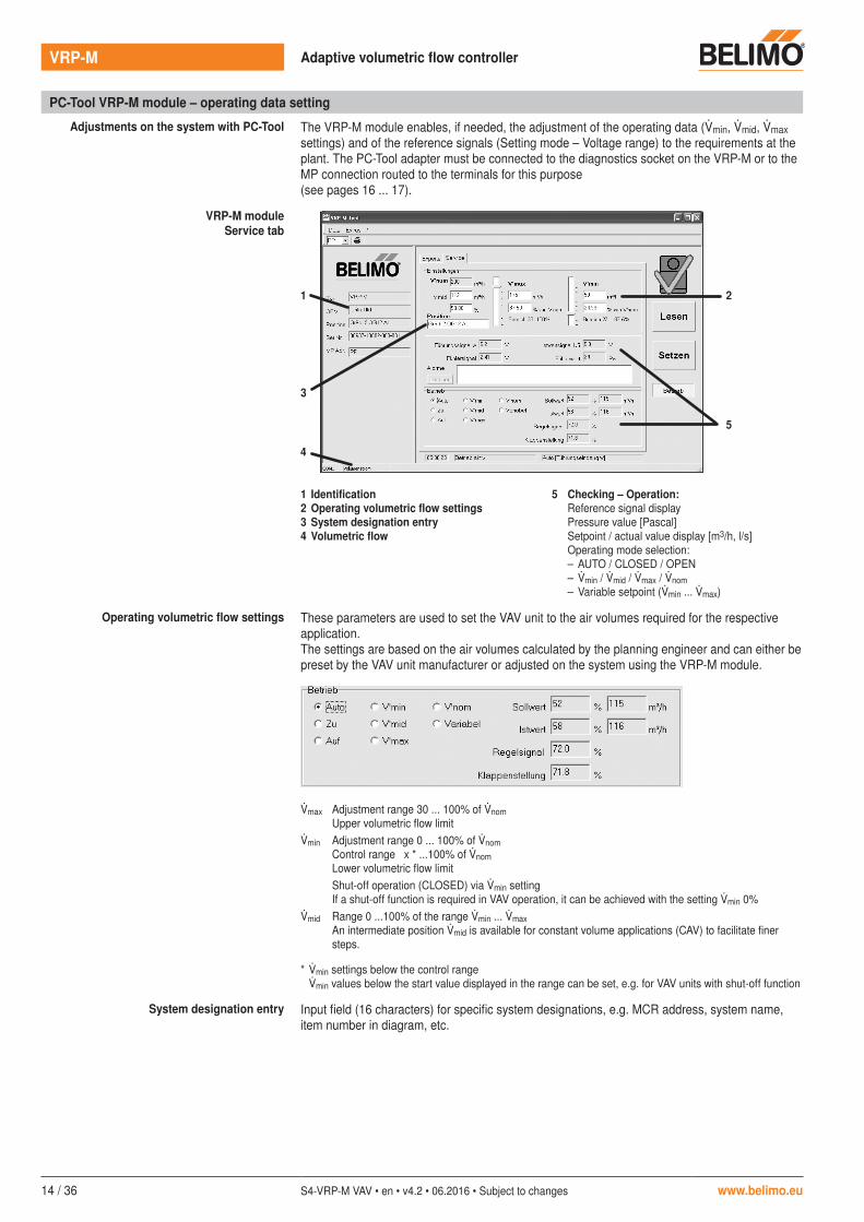
PC-Tool VRP-M module – operating data setting
Adjustments on the system with PC-Tool The VRP-M module enables, if needed, the adjustment of the operating data (min, mid, max settings) and of the reference signals (Setting mode – Voltage range) to the requirements at the plant. The PC-Tool adapter must be connected to the diagnostics socket on the VRP-M or to the MP connection routed to the terminals for this purpose (see pages 16 ... 17).
VRP-M moduleService tab
1 Identification2 Operating volumetric flow settings3 System designation entry4 Volumetric flow
5 Checking – Operation:Reference signal displayPressure value [Pascal]Setpoint / actual value display [m3/h, l/s]Operating mode selection:– AUTO / CLOSED / OPEN– min / mid / max / nom– Variable setpoint (min ... max)
Operating volumetric flow settings These parameters are used to set the VAV unit to the air volumes required for the respective application.The settings are based on the air volumes calculated by the planning engineer and can either be preset by the VAV unit manufacturer or adjusted on the system using the VRP-M module.
max Adjustment range 30 ... 100% of nomUpper volumetric flow limit
min Adjustment range 0 ... 100% of nomControl range x * ...100% of nomLower volumetric flow limitShut-off operation (CLOSED) via min settingIf a shut-off function is required in VAV operation, it can be achieved with the setting min 0%
mid Range 0 ...100% of the range min ... maxAn intermediate position mid is available for constant volume applications (CAV) to facilitate finer steps.
* min settings below the control range min values below the start value displayed in the range can be set, e.g. for VAV units with shut-off function
System designation entry Input field (16 characters) for specific system designations, e.g. MCR address, system name, item number in diagram, etc.
1
3
2
5
4

www.belimo.eu S4-VRP-M VAV • en • v4.2 • 06.2016 • Subject to changes 15 / 36
VRP-M Adaptive volumetric flow controller
PC-Tool VRP-M module – Operating data settings (continued)
VRP-M moduleExpert tab
1 Mode setting:Standard 0 ... 10 / 2 ... 10 V
3
4
VRP-M system information– VRP-M version and calibration value setting– Volumetric flow function– Sensor type– Actuator typeAmbient conditions– Height above sea level– Density
2 ControlIndividual setting– Reference signal w– Volumetric flow actual value signal U5
Mode setting Options: 0... 10 V / 2...10 V / individual settingThe mode setting acts on the reference signal w and the volumetric flow actual value signal U5.Variable settings are displayed here and can also be reset by selecting 2 ... 10 / 0 ... 10 V. Variable settings are entered in the «Control» field above.
ControlVariable setting
It is sometimes essential to adapt the reference signal w or the volumetric flow actual value signal U5 to the MCR system directly on the control system.The reference signal w and the volumetric flow actual value signal U5 can be set to different values (e.g. reference signal w: 2 ... 10 V / actual value signal U5: 0 ... 10 V).
Reference signal [w] / operating range min ... max
Start point: DC 0.0 ... 8 VStop point: DC 2.0 ... 10 V
Actual value signal [U5] / display range 0 ... 100% nom
Start point: DC 0.0 ... 8 VStop point: DC 2.0 ... 10 V
Ambient conditions With this function, the VRP-M solution and the VFD3 sensor can be adjusted to the geographical environment of the plant.
550 m
785 m
0 m
All relevant parameters can be entered through the «Ambient conditions» adjustment marker in the Expert tab. the following values are required for calculating the density and the correction value for the VFD3 signal:
Correction influence Typical setting value
Height above sea level large e.g. 1822 m, for St. Moritz,
SwitzerlandTemperature of medium medium Mean value, e.g. 19°C
Humid medium negligible Average, e.g. 45% r.h.
1
2
3
4
Plant
Sea level

16 / 36 S4-VRP-M VAV • en • v4.2 • 06.2016 • Subject to changes www.belimo.eu
VRP-M Adaptive volumetric flow controller
PC-Tool connection
The PC-Tool required for settings and servicing can be connected either directly to the 3-pin service socket on the VRP-M controller or via the MP connection (terminal 4). A level converter ZIP-USB-MP or ZIP-RS232 is required for communication.
Conventional operation (PP) Connection via service socket
VRP-M
AC 24 V
ZIP-RS232
1 2 5 OFF
Actuator
RS2
32
ON U
PP
~ T
AC 230 V
ZN23
0-24
VRP-MModul VRP-M
Modul
ZKS-MP
ZIP-USB-MP
USBUSB
AC/DC 24 V
Connection in control cabinet
VRP-M
1 2 4
VRP-MModul
PP/MP GND
ZK2-GEN
USB
ZIP-USB-MP
AC/DC 24 V
PC-Tool VRP-M module – Availability
The current version of the PC-Tool or the VRP-M module, respectively, and the associated documentation can be downloaded from www.belimo.eu.
white = GND (1)green = MP (4)blue = do not connect

www.belimo.eu S4-VRP-M VAV • en • v4.2 • 06.2016 • Subject to changes 17 / 36
VRP-M Adaptive volumetric flow controller
PC-Tool connection
MP bus mode The PC-Tool can only be connected via the bus master during MP bus operation because otherwise two MP masters would be connected on the same MP bus. This means the local connection to the VRP-M is not permitted to be operating at the same time as the MP master.
MP 1
MP-Bus
MP ..
UK24LON
2
MP 8
MP ..
- +
- +
VRP-MModul
ZKS-MP
USB
ZIP-USB-MP
Notes• The service plug integrated in the VRP-M is not
available with bus operation.• The MP bus cannot be used to transmit open
and closed-loop control functions if it is also used to connect the PC-Tool. Workaround: Undo MP bus (terminal 4) and use local MP plug or tool connection on the UK24...

18 / 36 S4-VRP-M VAV • en • v4.2 • 06.2016 • Subject to changes www.belimo.eu
VRP-M Adaptive volumetric flow controller
Service-Tool ZTH-GEN
Service-Tool for parameterisable and communicative Belimo actuators and VAV controllers. Local connection via service socket on the device or remote control via MP/PP connection.
Connection and supply The ZTH-GEN is supplied via the actuator/VAV controller. The connection is set up• directly at the Service socket of the actuator/VAV controller or • via the PP/MP connection, e.g. connection socket, in the control cabinet, room controller CR24
Local connection via service socket Connection to Cable type Connection
VRP-M ZK4-GEN
GND
~ / +
PP
1
2
4
3
ZK4-GEN
blue
ZTH-GEN connection in MP bus system:The MP connection should be separated from the MP bus while the ZTH-GEN is operating.
Direction connection to terminals Connection to Cable type Connection
VRP-M ZK2-GEN
white
blue
GND
PP
1
2
4
3
~ / +
turquoise
VAV-Universal actuators:The V actuators NM24A-S-ST, LMQ24A-SRV-ST and NMQ24A-SRV-ST, suitable for the VAV universal controller VRP-M (STP), have a tool connection, but are not tool-capable.
Connection in the MP bus systemZTH-VAV
▲ ▼ – + OK
MP1
MP4
MP2 MP3
MP7
MP5
MP6
MP8
Right ZTH-VAV
▲ ▼ – + OK
MP1
MP4
MP2 MP3
MP7
MP5
MP6
MP8
Wrong
Direct connection to the MP bus or MP master is not possible with the ZTH-GEN.Solution: Use the service socket on the VAV controller or temporarily disconnect the MP connection of the MP device from the MP bus and connect the ZTH-GEN to the MP connection.
Menu structure, handling The operating menu can be run through from both sides ▼▲.
▼▼
- + OK
z1
z2
z2
▼▼
+- OK
+- OK
Starting / ending The connection to the actuator/VAV controller is started by plugging in the RJ plug and terminated by unplugging it.
TypePosition
TypeSerial number
TypeFirmware
TypeDesignation
Option 1
Option 2
x ... y
x ... y
RJ plugs
Starting / ending
Data, settings Option, range
Device identification

www.belimo.eu S4-VRP-M VAV • en • v4.2 • 06.2016 • Subject to changes 19 / 36
VRP-M Adaptive volumetric flow controller
Configuration
Start Configuration 1. Press the key (OK) while simultaneously plugging in the connecting cable
2. Configuration menu display appears
Configuration menu Option / Display Setting Product range ExplanationHW Version Vx.xFW Version Vx.x
Display of the current hardware and firmware version of the ZTH-GEN
Text German / English -VAV unit m3/h / l/s / cfm VAVEPIV unit m3/h / l/min / gpm ValvesSupply. ...AC … V VHW: … %
Display of the current AC 24 V supply voltage, with direct connection to terminals (ZK2-GEN)
Start MP tester OK - MP bus diagnostics tool for system integrators. The MP tester is not a component part of this documentation.
PICCV function 0 / 1 Valves Belimo USEnable PICCV Wizard function
Expert Mode 1) 0 / 1 VAV 3) Enable VAV settings:– Switching mode,– set min / max to original values
(call up OEM setting)Advanced Mode 2) 0 / 1 VAV 3)
Fire protectionEnable settings:– VAV: Direction of rotation,– BF-Top: Adaption
Exit Configuration OK
Activate options 1) and 2) only as needed and with the respective know-how; the adjustment of the respective parameters requires special expertise.3) only for VAV-Compact
Functions for VAV product range
Menu tree
- + OK
z1z2▼
z2
z2
z2 +- OK
z1z2 +- OK
▼
▼
▼
▼
z1z2 +- OK▼
z1
z2
z2
▼
▼
▼
▼
▼
▼
z1z2 +- OK▼
z1▼
▼
▼
z1z2 +- OK
▼▼
TypePosition
TypeSerial number
TypeFirmware
TypeDesignation
Auto / Open / Closed / max / min / Stop
Start
Data, settings
Option, range
Device identification
VolumeSetpoint
125 m3/h124 m3/h
∆pPositionStep
164 Pa65%
>Auto<
Mode– new
2 ... 10 V0 ... 10 V
min– new
10 m3/h25 m3/h
Address– new
PPMP4
0 ... max
PP / MP1 / MP2 / MP3 ... MP8
Expe
rt
0 ... 10 / 2 ... 10 V
max– new
250 m3/h200 m3/h
nom 250 m3/h
min ... max

20 / 36 S4-VRP-M VAV • en • v4.2 • 06.2016 • Subject to changes www.belimo.eu
VRP-M Adaptive volumetric flow controller
Bus operation
The VRP-M system solution can be interconnected with other Belimo MP actuators (damper actuators, valve actuators, VAV-Compact controllers, VRP-M system solutions) thanks to the integrated communication principle over the Belimo MP bus. The maximum of eight Belimo MP devices are supplied with a digital control signal by the higher-level bus master and then opened to the position dictated by this signal.The switching from conventional to bus mode takes place automatically, as soon as an MP address (1...8) is assigned to the MP actuator.The Belimo MP devices can be integrated in the following systems:– LONWORKS®: The variables of Functional Profile 8110 can be used in conjunction with the
Belimo UK24LON interface.– EIB-Konnex: In connection with the Belimo UK24EIB interface– DDC controller with an integrated MP bus protocol: Available from several manufacturers
Damper position (starting with VRP-M Version V3.x)
(nvoAbsAngle – absolute actuator position in angular degrees ( ))The feedback signal, i.e. the network variable nvoAbsAngle, is not available for applications with NM24-V-ST actuators (old actuator generation).
MP bus cycle time
The cycle time of the MP bus must be noted when integrating setpoints and actual values. It is typically 2…8 s, depending on the number of connected bus users and integrated sensors.The local VRP-M control function is not affected by the cycle time. The cycle time of the MP bus must always be taken into account, however, when selecting setpoints via the MP bus.
Principle of operation Sensor integration (starting with VRP-M version V3.x)
The VRP-M can be connected to an additional active 0 ... 10 V signal in MP bus mode independently of the VAV control loop. The sensor signal is connected to the reference value input that is not used in MP bus mode (connection 3).The VRP-M acts in this capacity as an analogue/digital converter for the transmission of the sensor signal to the higher-level system. This must know the physical address (which sensor at which MP device) and be able to interpret the respective sensor signal.
Active sensor connection
Active 0 ... 10 V sensors for open and closed-loop control functions in the higher-level system, such as moisture or CO2 sensors. The cycle time must be taken into account in the implementation!Reference signal w setting if an active sensor is connected: 0 … 10 V
Integration of switches, passive resistance sensors
The VRP-M only supports active sensors with a 0 … 10 V output; i.e. no switches or passive sensors (resistance elements) can be integrated.
Principle of VRP-M in bus operation In bus operation, the VRP-M controller receives its reference signal from the higher-level control system and adjusts the volumetric flow to the fixed selected value in the range min ... max.If needed, the VAV range min ... max can be overridden in bus operation by fixed operating modes (control inputs z1 and z2).The following operating modes are available:– Shut-off operation – Damper CLOSED: The damper is moved into the CLOSED position in a
defined manner.– Operating modes mid / max: The VRP-M permanently moves the selected volumetric flow.– Flushing operation – damper OPEN: The damper can be opened for maximum ventilation, in
which case the volumetric flow control is deactivated.
Sensor
MP
4321 VRP-MPPw
~T
+_5 6 7
U5 y z
~T
T
+_
0 … 10 V
DC 24 V
www.belimo.eu S4-VRP-M VAV • en • v4.2 • 06.2016 • Subject to changes 21 / 36
VRP-M Adaptive volumetric flow controller
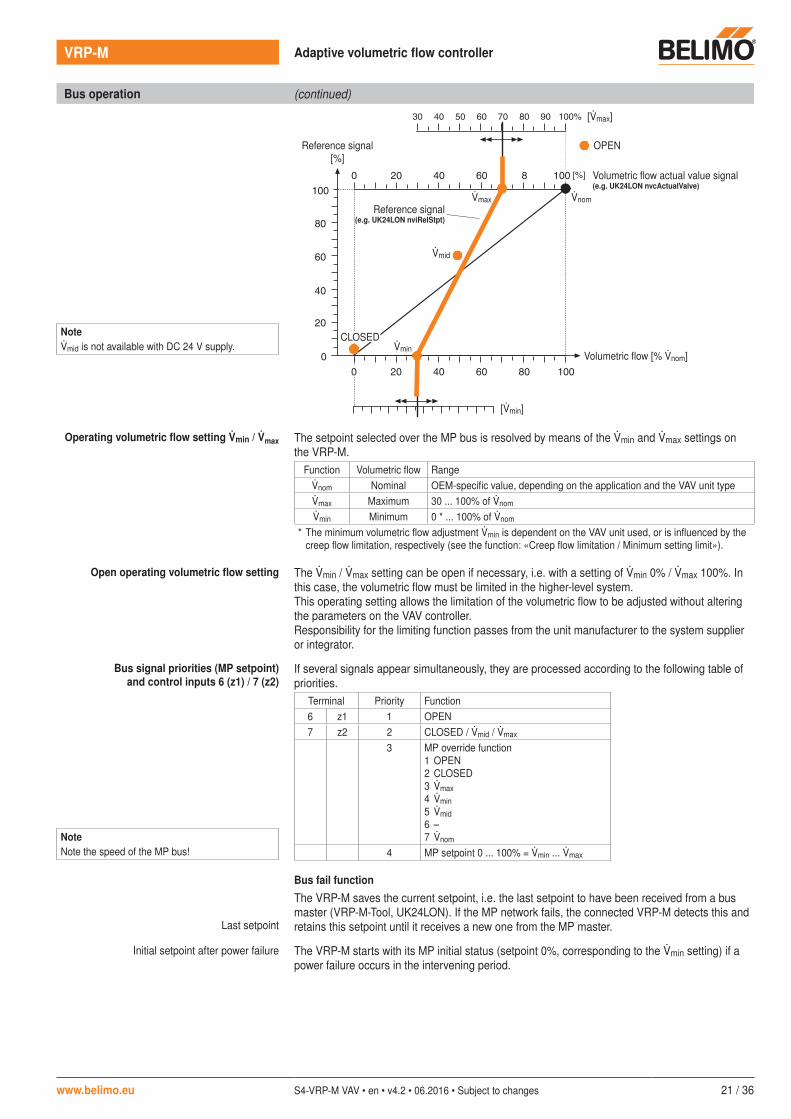
Bus operation (continued)
Operating volumetric flow setting min / max The setpoint selected over the MP bus is resolved by means of the min and max settings on the VRP-M.
Function Volumetric flow Rangenom Nominal OEM-specific value, depending on the application and the VAV unit typemax Maximum 30 ... 100% of nom
min Minimum 0 * ... 100% of nom
* The minimum volumetric flow adjustment min is dependent on the VAV unit used, or is influenced by the creep flow limitation, respectively (see the function: «Creep flow limitation / Minimum setting limit»).
Open operating volumetric flow setting The min / max setting can be open if necessary, i.e. with a setting of min 0% / max 100%. In this case, the volumetric flow must be limited in the higher-level system.This operating setting allows the limitation of the volumetric flow to be adjusted without altering the parameters on the VAV controller.Responsibility for the limiting function passes from the unit manufacturer to the system supplier or integrator.
Bus signal priorities (MP setpoint)and control inputs 6 (z1) / 7 (z2)
If several signals appear simultaneously, they are processed according to the following table of priorities.
Terminal Priority Function6 z1 1 OPEN7 z2 2 CLOSED / mid / max
3 MP override function1 OPEN2 CLOSED3 max4 min5 mid6 –7 nom
4 MP setpoint 0 ... 100% = min ... max
Bus fail function
The VRP-M saves the current setpoint, i.e. the last setpoint to have been received from a bus master (VRP-M-Tool, UK24LON). If the MP network fails, the connected VRP-M detects this and retains this setpoint until it receives a new one from the MP master.
Initial setpoint after power failure The VRP-M starts with its MP initial status (setpoint 0%, corresponding to the min setting) if a power failure occurs in the intervening period.
Reference signal[%]
[max]
CLOSED
OPEN
nommax
[min]
min
Volumetric flow actual value signal(e.g. UK24LON nvcActualValve)
Volumetric flow [% nom]
Reference signal(e.g. UK24LON nviRelStpt)
Notemid is not available with DC 24 V supply.
NoteNote the speed of the MP bus!
Last setpoint
mid

22 / 36 S4-VRP-M VAV • en • v4.2 • 06.2016 • Subject to changes www.belimo.eu
MP bus
Topology The cables of up to eight actuators can be laid in a freely definable topology. The following topologies are permitted: star, ring, tree or mixed forms.
Connection The network consists of a 3-pin connection (MP communication and 24 V supply). Neither special cables nor terminating resistors are required. Power can be supplied either through the bus cable or from a local power supply.
MP
4321 VRP-MMPw
~T
+_5 6 7U5 z1 z2
4321 VRP-MMPw
~T
+_5 6 7U5 z1 z2
~T
+_AC 24 VDC 24 V
Network Up to eight MP actuators can be connected in a network (VAV-Compact, VRP-M etc.).
Supply with AC or DC voltage
Nominal voltage AC 24 V, 50/60 Hz, DC 24 VPower supply range AC 19.2...28.8 V, DC 21.6...26.4 VDimensioning See «Technical data», page 7
MP bus signal cable length
The cable lengths are limited:– By the sum of the performance data of the connected devices, e.g. VAV controllers, actuators– By the type of supply (AC 24 V or DC 24 V)– By the cable cross-section.
For more information about planning and installation, see www.belimo.com
– VAV-Compact NMV-D2-MP products informationBus and communication systems section
Addressing If the VRP-M system solution is integrated in a bus system, each connected VRP-M must be assigned an MP address in the range 1 ... 8.
Procedure
– Start the addressing procedure on the MP bus master VRP-M-Tool, UK24LON etc.– For the procedure, see the documentation of the bus master used– Procedure with VRP-M-Tool:
a) Select Addressing via serial number Enter the serial number of the VRP-M (sticker on the VRP-M, display in the VRP-M-Tool)
b) Select addressing with acknowledgement on the VRP-M Acknowledge the selected address by pressing the Set key on the desired VRP-M. If the Set key is pressed, then the Power LED will flash (green)
Up to 8 MP bus users
Additional MP bus users
VRP-M Adaptive volumetric flow controller

www.belimo.eu S4-VRP-M VAV • en • v4.2 • 06.2016 • Subject to changes 23 / 36
Static differential pressure sensors for neutral to slightly aggressive gases• Measuring range, type-dependent,
0 ... 100 / 300 / 600 Pa• Cable connection with plug suitable for
VAV-Universal VRP-M
VFP-300 VFP-600
Technical data
Electrical data SupplyConnection
DC 15V (from VRP-M controller)1 m cable with 4-pin plug(suitable for VRP-M)
Functional data Type, principle of operation Pressure measurement by means of diaphragm (static, inductive)
Measuring range See «Type overview»Overload protection See «Type overview»Measuring medium Neutral to slightly aggressive gasesParts in contact with medium Ni, Al, CuBe, PULinearity ±1% of final value (FS)Switching differential Max. 0.1% of final valueTemperature sensitivity Zero
Measuring rangeSee «Type overview»t = +10 ... 40°C (reference temperature t0 = 25°C)
Mounting orientation Upright (nipple on bottom or side)Position dependency Max. ±4.5 Pa
With 90° rotation around horizontal spindleConnection for pressure hoses Hose nipple
for hose with 4 ... 6 mm interior diameter
Safety Protection class III Safety extra-low voltageDegree of protection IP42EMC CE according to 2004/108/ECPrinciple of operation Type 1 (EN 60730-1)Ambient temperature 0 ... +50°CNon-operating temperature –10 ... +70°CAmbient humidity 5 ... 95% r.h., non-condensing (EN 60730-1)Maintenance Maintenance-free
Dimensions / Weight Dimensions See «Dimensions» on page 35Weight See «Type overview»
Type overview
Type Measuring ranges Overload protection Temperature sensitivity of zero Weight
VFP-100 0 ... 100 Pa max. 500 Pa ±0.1% / K Approx. 500 gVFP-300 0 ... 300 Pa Max. 1500 Pa ±0.05% / K Approx. 280 gVFP-600 0 ... 600 Pa Max. 3000 Pa ±0.05% / K Approx. 280 g
Safety notes
!• The pressure sensors must not be used outside the specified field of application,
especially in aircraft or in any other airborne means of transport.• It may only be installed by suitably trained personnel.
Legal regulations and regulations issued by authorities must be observed during installation.• The devices do not contain any parts that can be replaced or repaired by the user.• The devices contain electrical and electronic components and are not allowed to be disposed
of as household refuse. All locally valid regulations and requirements must be observed.
Technical data sheet VFP-..
VFP-100

24 / 36 S4-VRP-M VAV • en • v4.2 • 06.2016 • Subject to changes www.belimo.eu
VFP-.. Static pressure value sensors
Product features
Application Together with a VRP-M controller and a Belimo damper actuator, the VFP-.. static pressure sensors form a control system for pressure-independent variable (VAV) and constant (CAV) volumetric flow controls.The pressure sensors are used for static differential pressure measurement with pick-up devices installed in air ducts. They can also be used with contaminated or mildly aggressive air 1). Their robust design makes them ideal for installation in laboratories, clean room systems and industrial applications.
Principle of operation A high-quality metal diaphragm is used in the sensor. The measured pressure produces a corresponding diaphragm stroke, which is detected inductively and converted to a pressure-linearised output signal.The measuring signal is influenced by the mounting position due to the dead weight of the diaphragm. The sensor is calibrated in vertical position at the factory, although it can, if necessary, e.g. if installed in another position, be readjusted at the utilisation site.The temperature is compensated to reduce drift to a minimum. The wear-free, inductive measurement method guarantees maintenance-free operation.
1) See «Technical data», page 23For zero offset and more information, see «System description», page 9
Electrical installation
The ready-to-connect sensor unit is connected to the VRP-M controller with the 4-pin plug.

www.belimo.eu S4-VRP-M VAV • en • v4.2 • 06.2016 • Subject to changes 25 / 36
Technical data sheet VFD3
Technical data
Electrical data Nominal voltage AC 24 V, 50/60 Hz / DC 15…24 VNominal voltage range AC 19.2 … 28.8 V / DC 13.5 … 28.8 VPower consumption Operation
Dimensioning0.35 W0.75 VA
Connection Pre-mounted 1 m cable with 4-pin plug, compatible with VRP-M
Functional data Type, principle of operation �p sensor with dynamic measurement principleRange of use, measuring medium Outside air/exhaust air in the comfort zone with
sensor-compatible mediaMedium temperature 0 ... 50°CHumidity of the medium 5 ... 95% r.h., non-condensatingMaterials in contact with medium Glass, epoxy resin, PA, TPEConnection for pressure hoses Hose nipple Ø 6 mm,
with + and – connection designationAdjustment range Can be selected with DIP switch:
0 … 100 Pa0 … 300 Pa (default setting)0 … 600 Pa–20 … 100 Pa (cannot be used with the VRP-M)
Accuracy ±1 Pa in the pressure range –20 … 20 Pa±5% in the pressure range 20 … 500 Pa
Zero <±1%, no balancing requiredLoading capacity ±5000 PaInstallation position Any, no reset necessaryResponse time <50 ms (<100 ms after Power-Up)Output signal 0 ... 10 V, max. load 1 mA
Safety Protection class III Safety extra-low voltageDegree of protection IP40EMC CE according to 2004/108/ECPrinciple of operation Type 1Rated current voltage 0.8 kVControl pollution degree 3Ambient temperature 0 ... +50°CNon-operating temperature –20 ... +60°CAmbient humidity 0 ... 95% r.h., non-condensating
Dimensions / Weight Dimensions (H x W x D) See «Dimensions» on page 35Weight Approx. 170 g
Dynamic pressure value sensor for room ventilation applications in the comfort zone• Adjustment range:
adjustable with DIP switch in the range between 0 ... 100 / 300 / 600 Pa
• Cable connection with plug, suitable for VAV-Universal VRP-M
Safety notes
!• The pressure sensors must not be used outside the specified field of application,
especially in aircraft or in any other airborne means of transport.• It may only be installed by suitably trained personnel.
Legal regulations and regulations issued by authorities must be observed during installation.• The devices contain electrical and electronic components and are not allowed to be disposed
of as household refuse. All locally valid regulations and requirements must be observed.
NoteA setting of 0 ... 600 Pa can be measured differential pressures up to 500 Pa.
. . . . . . . . . . . .. . . . .

26 / 36 S4-VRP-M VAV • en • v4.2 • 06.2016 • Subject to changes www.belimo.eu
Product features
Application Recording of �p values in conventional heating, ventilation and air conditioning room ventilation comfort applications, e.g.:– Negative and positive pressure in the duct system with reference to the ambient pressure– Volumetric flow of supply air/exhaust air in combination with Belimo VAV universal controller
VRP-M
Principle of operation The integrated maintenance-free D3 pressure value sensor functions in accordance with the dynamic measurement principle. The differential pressure �p present at the sensor is available at the analogue output as 0 ... 10 V value.
VFD3 Dynamic pressure value sensor
NoteDynamic pressure sensor VFD3The pressure range of the VFD3 is set in the factory by the manufacturer of the VAV unit and configured accordingly in the VRP-M. It is mandatory that an adjustment of the pressure range requires an adaptation in the VRP-M configuration.The pressure range –20 ... 100 Pa cannot be used with the VRP-M.

www.belimo.eu S4-VRP-M VAV • en • v4.2 • 06.2016 • Subject to changes 27 / 36
Technical data sheet LMQ24A-SRV-ST
Fast-running damper actuator for VRP-M system solution• Torque 4 Nm• Running time 2.5 s
Technical data
Electrical data Supply AC/DC 24 V (from VRP-M controller)Power consumption Operation
Rest positionDimensioning
13 W @ nominal torque1.5 W23 VA
Connection 0.5 m cable with 6-pin plug(suitable for VRP-M)
Functional data Torque (nominal torque) Min. 4 Nm @ nominal voltageDirection of rotation As an option with switch 0 / 1Direction of motion at Y = 0V In switch position 0 or 1Angle of rotation max. 95° , mechanical end stops adjustableRunning time 2.5 s / 90°Sound power level 52 dB (A)Position indication Mechanical, plug-in
Safety Protection class III Safety extra-low voltageDegree of protection IP54 in all mounting positionsEMC CE according to 2004/108/ECPrinciple of operation Type 1 (EN 60730-1)Ambient temperature –30 ... +50°CNon-operating temperature –40 ... +80°CAmbient humidity 95% r.h., non-condensing (EN 60730-1)Maintenance Maintenance-free
Dimensions / Weight Dimensions See «Dimensions» on page 35Weight Approx. 810 g
Safety notes
!• The actuator is not allowed to be used outside the specified field of application, especially in
aircraft or in any other airborne means of transport.• It may only be installed by suitably trained personnel.
Legal regulations and regulations issued by authorities must be observed during installation.• The device may only be opened at the manufacturer's site. It does not contain any parts that
can be replaced or repaired by the user.• The cable must not be removed from the device.• Self adaptation is necessary when the system is commissioned and after each adjustment of
the angle of rotation (press the adaptation push-button).• When calculating the torque required, the specifications supplied by the damper
manufacturers (cross-section, construction, place of installation), and the ventilation conditions must be observed.
• The device contains electrical and electronic components and is not allowed to be disposed of as household refuse. All locally valid regulations and requirements must be observed.
LimitationThe use of VRP-M with fast running actuators is not permitted for the optimiser function!

28 / 36 S4-VRP-M VAV • en • v4.2 • 06.2016 • Subject to changes www.belimo.eu
LMQ24A-SRV-ST Fast-running damper actuator for VRP-M system solution
Product features
Simple direct mounting Simple direct mounting on the damper spindle with a universal spindle clamp; a universal mounting bracket is enclosed to prevent the actuator from rotating.
Manual override Manual override with self-resetting push-button.The position calculation is synchronised in order to prevent deviations as a result of manualoverride. This synchronisation acts at the same time as a simple functional check (see below «Synchronisation»).
Adjustable angle of rotation The angle of rotation is adapted to the available setting range by the manufacturer of the damper by means of integrated, mechanical end stops.Permissible range: 63 ... 100%.
Adaption – Adaptation to the available angle of rotation
This function detects the upper and lower spindle end stops and stores them in the actuator. The running time and the operating range are adapted to the available angle of rotation. Detection of the mechanical end stops enables a gentle approach to the end position and protects the actuator and damper mechanisms. The actuator moves first to the top, then to the bottom spindle end stops when the supply voltage is switched on for the first time, i.e. at the time of commissioning or after pressing the «Adaption» key.
Home position Actuation of the «Gear disengagement» key causes the actuator to move to home position. This function is performed by the actuator, even when the supply voltage is restored, if the «Gear disengagement» key was pressed during the electricity interruption.
After this procedure, the actuator then moves into the position defined by the system.
Functional check An extremely simple functional check of the dampers is possible: The gearbox can be disengaged simply by pressing the «gear disengagement» key on the housing. As long as the key remains pressed, the damper can be operated manually.
High functional reliability The actuators are overload-proof, require no limit switches and automatically stop when the end stop is reached.
Electrical installation
The ready-to-connect actuator unit is connected to the VRP-M controller with the 6-pin plug.
Display and operating elements
1 Direction of rotation switchSwitching over: Direction of rotation changes
2 Push-button and LED display greenOff:Illuminated:Press key:
No power supply or faultOperationInitiates angle of rotation adaptation, followed by standard mode
3 Push-button and LED display yellowOff:Illuminated:Press key:
Standard modeAdaption or synchronisation process activeNo function
4 Gear disengagement keyPress key:Release key:
Gearbox disengaged, motor stops, manual override possibleGearbox engaged, synchronisation starts, followed by standard mode
5 Communication (PC-Tool, ZTH-GEN) is blocked for this actuator type
4
1
2
3
Caution!An adaption must be carried out when the system is commissioned or whenever the end stops for angle of rotation limiting are adjusted (press the «Adaption» push-button once).
!
5
Pos. direction of rotation switch Home positionY = 0 Left end stop
Y = 0 Right end stop1
0 ccw
cw

www.belimo.eu S4-VRP-M VAV • en • v4.2 • 06.2016 • Subject to changes 29 / 36
Fast-running damper actuator for VRP-M system solution• Torque 8 Nm• Running time 4 s
Technical data
Electrical data Supply AC/DC 24 V (from VRP-M controller)Power consumption Operation
Rest positionDimensioning
12 W @ nominal torque1.5 W18 VA
Connection 0.5 m cable with 6-pin plug(suitable for VRP-M)
Functional data Torque (nominal torque) Min. 8 Nm @ nominal voltageDirection of rotation As an option with switch 0 / 1Direction of motion for Y = 0 V In switch position 0 or 1 Angle of rotation max. 95° , mechanical end stops adjustableRunning time 4 s / 90°Sound power level 52 dB (A)Position indication mechanical, plug-in
Safety Protection class III Safety extra-low voltageDegree of protection IP54 in all mounting positionsEMC CE according to 2004/108/ECPrinciple of operation Type 1 (EN 60730-1)Ambient temperature –30 ... +50°CNon-operating temperature –40 ... +80°CAmbient humidity 95% r.h., non-condensing (EN 60730-1)Maintenance Maintenance-free
Dimensions / Weight Dimensions See «Dimensions» on page 35Weight Approx. 930 g
Technical data sheet NMQ24A-SRV-ST
Safety notes
!• The actuator is not allowed to be used outside the specified field of application, especially in
aircraft or in any other airborne means of transport.• It may only be installed by suitably trained personnel.
Legal regulations and regulations issued by authorities must be observed during installation.• The device may only be opened at the manufacturer's site. It does not contain any parts that
can be replaced or repaired by the user.• The cable must not be removed from the device.• Self adaption is necessary when the system is commissioned and after each adjustment of
the angle of rotation (press the Adaption push-button once).• When calculating the torque required, the specifications supplied by the damper
manufacturers (cross-section, construction, place of installation), and the ventilation conditions must be observed.
• The device contains electrical and electronic components and is not allowed to be disposed of as household refuse. All locally valid regulations and requirements must be observed.

30 / 36 S4-VRP-M VAV • en • v4.2 • 06.2016 • Subject to changes www.belimo.eu
NMQ24A-SRV-ST Fast-running damper actuator for VRP-M system solution
Product features
Simple direct mounting Simple direct mounting on the damper spindle with a universal spindle clamp; a universal mounting bracket is enclosed to prevent the actuator from rotating.
Manual override Manual override with self-resetting push-button.The position calculation is synchronised in order to prevent deviations as a result of manualoverride. This synchronisation acts at the same time as a simple functional check (see below «Synchronisation»).
Adjustable angle of rotation The angle of rotation is adapted to the available setting range by the manufacturer of the damper by means of integrated, mechanical end stops.Permissible range: 63 ... 100%.
Adaption – Adaptation to the available angle of rotation
This function detects the upper and lower spindle end stops and stores them in the actuator. The running time and the operating range are adapted to the available angle of rotation. Detection of the mechanical end stops enables a gentle approach to the end position and protects the actuator and damper mechanisms. The actuator moves first to the top, then to the bottom spindle end stops when the supply voltage is switched on for the first time, i.e. at the time of commissioning or after pressing the «Adaption» key.
Home position Actuation of the «Gear disengagement» key causes the actuator to move to home position. This function is performed by the actuator, even when the supply voltage is restored, if the «Gear disengagement» key was pressed during the electricity interruption.
After this procedure, the actuator then moves into the position defined by the system.
Functional check An extremely simple functional check of the dampers is possible: The gearbox can be disengaged simply by pressing the «gear disengagement» key on the housing. As long as the key remains pressed, the damper can be operated manually.
High functional reliability The actuators are overload-proof, require no limit switches and automatically stop when the end stop is reached.
Electrical installation
The ready-to-connect actuator unit is connected to the VRP-M controller with the 6-pin plug.
Display and operating elements
1 Direction of rotation switchSwitching over: Direction of rotation changes
2 Push-button and LED display greenOff:Illuminated:Press key:
No power supply or faultOperationInitiates angle of rotation adaptation, followed by standard mode
3 Push-button and LED display yellowOff:Illuminated:Press key:
Standard modeAdaption or synchronisation process activeNo function
4 Gear disengagement keyPress key:Release key:
Gearbox disengaged, motor stops, manual override possibleGearbox engaged, synchronisation starts, followed by standard mode
5 Communication (PC-Tool, ZTH-GEN) is blocked for this actuator type
4
1
2
3
Caution!An adaption must be carried out when the system is commissioned or whenever the end stops for angle of rotation limiting are adjusted (press the «Adaption» push-button once).
!
5
Pos. direction of rotation switch Home positionY = 0 Left end stop
Y = 0 Right end stop1
0 ccw
cw

www.belimo.eu S4-VRP-M VAV • en • v4.2 • 06.2016 • Subject to changes 31 / 36
Technical data sheet NM24A-V-ST
Damper actuator for VRP-M system solution• Torque 10 Nm• Running time 150 s
Technical data
Electrical data Nominal voltage AC 24 V, 50/60 Hz / DC 24 V(from VRP-M)
Power consumption OperationRest positionDimensioning
3.5 W @ nominal torque1.25 W6 VA
Connection 0.5 m cable with 6-pin plug(suitable for VRP-M)
Functional data Torque (nominal torque) Min. 10 Nm @ nominal voltagePosition accuracy ±5%Direction of rotation As an option with switch 0 / 1Direction of motion at Y = 2V In switch position 0 or 1 Angle of rotation max. 95°
Mechanical end stops adjustableRunning time 150 sSound power level max. 35 dB (A)Position indication mechanical, plug-in
Safety Protection class III Safety extra-low voltageDegree of protection IP54 in all mounting positionsEMC CE according to 2004/108/ECPrinciple of operation Type 1 (EN 60730-1)Ambient temperature –30 ... +50°CNon-operating temperature –40 ... +80°CAmbient humidity 95% r.h., non-condensing (EN 60730-1)Maintenance Maintenance-free
Dimensions / Weight Dimensions See «Dimensions» on page 35Weight Approx. 710 g
Safety notes
!• The actuator is not allowed to be used outside the specified field of application, especially in
aircraft or in any other airborne means of transport.• It may only be installed by suitably trained personnel.
Legal regulations and regulations issued by authorities must be observed during installation.• The device may only be opened at the manufacturer's site. It does not contain any parts that
can be replaced or repaired by the user.• The cable must not be removed from the device.• When the required torque is calculated, the cross section, design and installation site as well
as the air flow conditions must be observed.• The device contains electrical and electronic components and is not allowed to be disposed
of as household refuse. All locally valid regulations and requirements must be observed.

32 / 36 S4-VRP-M VAV • en • v4.2 • 06.2016 • Subject to changes www.belimo.eu
NM24A-V-ST Damper actuator for VRP-M system solution
Accessories
Description Data sheet
Electrical accessories Auxiliary switch S..A.. T2 - S..A..Feedback potentiometer P..A.. T2 - P..A..
Mechanical accessories Shaft extension AV6-20 T2 - Z-NM..A..
Product features
Simple direct mounting Simple direct mounting on the damper spindle with a universal spindle clamp, supplied with a universal mounting bracket to prevent the actuator from rotating.
Manual override Manual override with self-resetting push-button possible (gear disengagement for as long as the button is pressed).
Adjustable angle of rotation Adjustable angle of rotation with mechanical end stops.
Adaption Angle-of-rotation sensing and adaptation of the control range. Triggered by pressing a button on the actuator, with LEDs for status display.
High functional reliability The actuator is overload protected, requires no limit switches and automatically stops when the end stop is reached.
Electrical installation
The ready-to-connect actuator unit is connected to the VRP-M controller with the 6-pin plug.
Display and operating elements
1 Direction of rotation switchSwitching over: Direction of rotation changes
2 Push-button and LED display greenOff:Illuminated:Press key:
No power supply or faultOperationInitiates angle of rotation adaptation, followed by standard mode
3 Push-button and LED display yellowOff:Illuminated:Press key:
Standard modeAdaption or synchronisation process activeNo function
4 Gear disengagement keyPress key:Release key:
Gearbox disengaged, motor stops, manual override possibleGearbox engaged, synchronisation starts, followed by standard mode
5 Communication (PC-Tool, ZTH-GEN) is blocked for this actuator type
4
1
2
3
5

www.belimo.eu S4-VRP-M VAV • en • v4.2 • 06.2016 • Subject to changes 33 / 36
Technical data
Electrical data Nominal voltage AC 24 V, 50/60 Hz / DC 24 V(from VRP-M)
Power consumption OperationRest positionDimensioning
8.5 W @ nominal torque3.5 W11 VA
Connection 1 m cable with 6-pin plug (compatible with VRP-M)
Functional data Torque MotorSpring-return
Min. 20 Nm @ nominal voltageMin. 20 Nm
Position accuracy ±5%Direction of rotation Motor
Spring-returnas an option with switch / As an option by installation L / R
Direction of rotation for Y = 0 V in switch position 1 or 0Manual override With hand crank and interlocking switchAngle of rotation max. 95° (can be limited by
adjustable mechanical stop)Running time Motor
Spring-return≤150 s / 90°≤20 s @ –20 ... 50°C / max. 60 s @ –30°C
Sound power level MotorSpring-return
≤40 dB (A) @ 150 s running time≤62 dB (A)
Service life Min. 60,000 emergency settings
Safety Protection class III Safety extra-low voltageDegree of protection IP54EMC CE according to 2004/108/ECCertification Certified in accordance with IEC/EN 60730-1 and IEC/
EN 60730-2-14 Principle of operation Type 1.AARated current voltage 0.8 kVControl pollution degree 3Ambient temperature –30 ... +50°CNon-operating temperature –40 ... +80°CAmbient humidity 95% r.h., non-condensingMaintenance Maintenance-free
Dimensions / Weight Dimensions See «Dimensions» on page 35Weight Approx. 2.3 kg
Technical data sheet SF24A-V-ST
Spring-return actuator with emergency setting function for VAV and CAV units in ventilation and air conditioning systems for building services installations• Torque 20 Nm• Running time 150 s

34 / 36 S4-VRP-M VAV • en • v4.2 • 06.2016 • Subject to changes www.belimo.eu
Product features
Principle of operation The actuator is controlled by the Belimo VRP-M controller and travels to the position defined by the control signal.
Simple direct mounting Simple direct mounting on the damper spindle with a universal spindle clamp; a universal mounting bracket is enclosed to prevent the actuator from rotating.
Adjustable angle of rotation Adjustable angle of rotation with mechanical end stop.
Adaption Angle-of-rotation sensing and adaptation of the control range. Triggered by pressing a button on the actuator, with LEDs for status display.
High functional reliability The actuator is overload protected, requires no limit switches and automatically stops when the end stop is reached.
Accessories
Description Data sheet
Electrical accessories Auxiliary switch S2A-F
Mechanical accessories Various accessories (spindle clamps, shaft extensions, etc.) T2 - Z-SM..A..
Electrical installation
The ready-to-connect actuator unit is connected to the VRP-M controller with the 6-pin plug.
Display and operating elements
1 Membrane key and LED display greenOff:Illuminated:Press key:
No power supply or faultOperationInitiates angle of rotation adaptation, followed by standard mode
2 Membrane key and LED display yellowOff:Illuminated:Press key:
Standard modeAdaption or synchronisation process activeNo function
3 Communication (PC-Tool, ZTH-GEN) is blocked for this actuator type
Operating elements The elements manual override, locking switch and direction of rotation switch are available on both sides.
1 2
3
SF24A-V-ST Spring-return actuator for VRP-M system solution
Safety notes
!• The actuator is not allowed to be used outside the specified field of application, especially in
aircraft or in any other airborne means of transport.• It may only be installed by suitably trained personnel.
Legal regulations and regulations issued by authorities must be observed during installation.• The device may only be opened at the manufacturer's site. It does not contain any parts that
can be replaced or repaired by the user.• The cable must not be removed from the device.• The device contains electrical and electronic components and is not allowed to be disposed
of as household refuse. All locally valid regulations and requirements must be observed.

www.belimo.eu S4-VRP-M VAV • en • v4.2 • 06.2016 • Subject to changes 35 / 36
Dimensions
Dimensional drawings of VRP-M controller
Dimensional drawings of VFP-100 sensor
Dimensional drawings of VFP-300 and VFP-600 sensors
Dimensional drawings LMQ24A-SRV-ST
Dimensional drawings NMQ24A-SRV-ST
5 54
4.5
130140153
4543
88
5
58
12015150
135
4080
ø 4.5
49
661290
81
25.5
51
124
50
75 80
25 41121
Dimensional drawings NM24A-V-ST
88
30 41131
77
52
139
124
50
75 80
25 41121
Dimensional drawings SF24A-V-ST
6020
.512
.5
93
2-F
RO
NT
32 27
162
172
182
236
98
80
Dimensional drawings of VFD3
39
90
99110
51
Damper spindle Length≥40 8 ... 26.7 ≥8 ≤26.7
* ≥20 8 ... 20 ≥8 ≤20
* Option (Accessory K-NA)
Damper spindle Length≥42 8 ... 26.7 ≥8 ≤26.7
* ≥20 8 ... 20 ≥8 ≤20
* Option (Accessory K-SA)
Variant 1a:¾“-spindle clamp (with insertion part) EU StandardDamper spindle Length
≥8510 ... 22 10 14 ... 25.4
≥15Variant 1b:1“-spindle clamp (without insertion part) EU StandardDamper spindle Length
≥85 19 ... 25.4(26.7) 12 ... 18
≥15
Damper spindle Length≥40 8 ... 26.7 ≥8 ≤26.7
* ≥20 8 ... 20 ≥8 ≤20
* Option (Accessory K-NA)

All inclusive.
Belimo worldwide: www.belimo.com
5 years Guarantee
Worldwide present
Complete assortment from a single source
Examined Quality
Short delivery time
Comprehensive support
Headquarters Subsidiaries, Representatives and Agencies
BELIMO Holding AGBrunnenbachstrasse 1CH-8340 HinwilTel. +41 (0)43 843 61 11Fax +41 (0)43 843 62 [email protected]
AgentinaAustraliaBahrainBelgiumBosnia-HerzegovinaBrazilBulgariaCanadaChileCroatiaCyprusCzech Republic
DenmarkEgyptEstoniaFinlandFranceGreat BritainGermanyGreeceHong KongHungaryIcelandIndiaIndonesiaIrelandIsraelItalyJapanJordanKuwaitLatvia
LebanonLiechtensteinLithuaniaLuxembourgMalaysiaMexicoMoroccoNetherlandsNew ZealandNorwayOmanPakistanPeople’s Republic of ChinaPhilippinesPolandPortugalQatarRepublic of Korea (South Korea)
RumaniaRussiaSaudi ArabiaSingaporeSlovakiaSloveniaSouth AfricaSpainSwedenSwitzerlandTaiwanTurkeyUkraineUnited Arab EmiratesUnited States of America