BUS TRACKER - CDR 2012 Capstone Senior design Colorado University at Boulder Instructor: Tom.Brown...
30
BUS TRACKER - CDR 2012 Capstone Senior design Colorado University at Boulder Instructor: Tom.Brown Sam.Siewert Team- Winning Team member: Bin Wang Erik Ware David Zigman Emile Bahdi Slides made by: Bin Wang
Transcript of BUS TRACKER - CDR 2012 Capstone Senior design Colorado University at Boulder Instructor: Tom.Brown...

BUS TRACKER - CDR
2012 Capstone Senior design Colorado University at BoulderInstructor: Tom.Brown Sam.Siewert
Team- Winning
Team member:
Bin Wang Erik WareDavid Zigman Emile Bahdi
Slides made by: Bin Wang
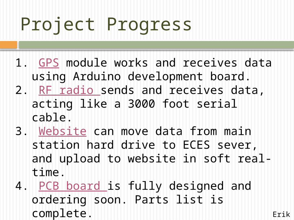
Project Progress
1. GPS module works and receives data using Arduino development board.
2. RF radio sends and receives data, acting like a 3000 foot serial cable.
3. Website can move data from main station hard drive to ECES sever, and upload to website in soft real-time.
4. PCB board is fully designed and ordering soon. Parts list is complete.
5. Finish a prototype design for the user station.
Erik
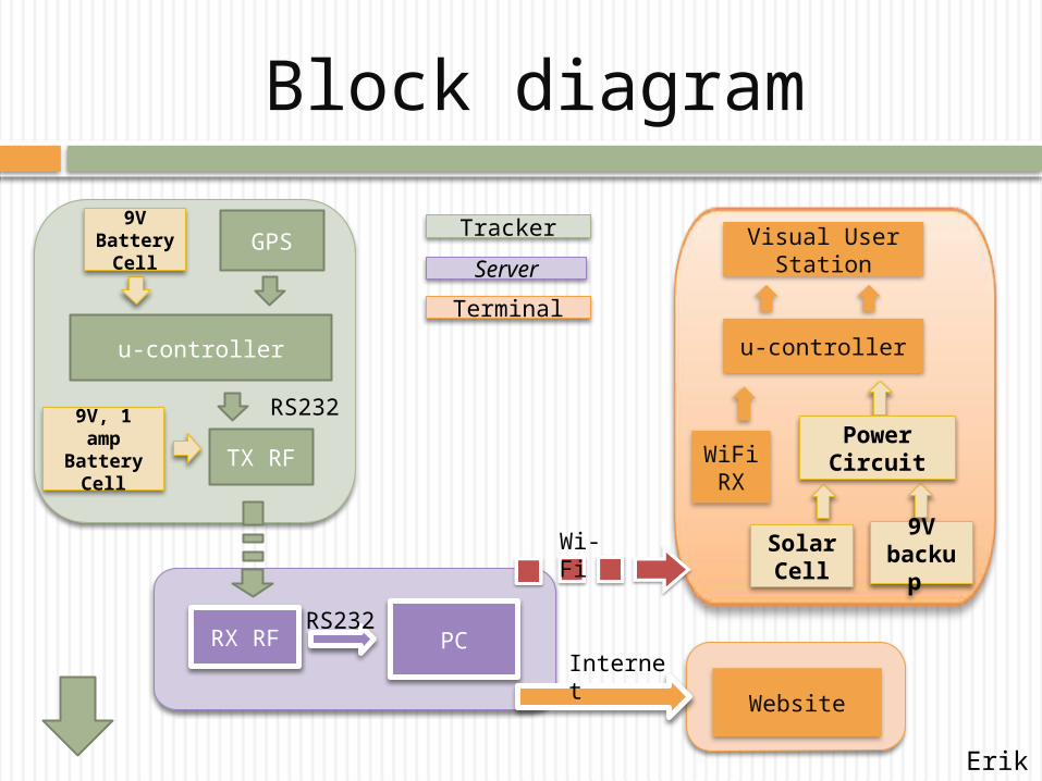
Block diagram
PCRX RF
Website
Solar Cell
u-controller
Wi-Fi
RS232
GPS
u-controller
TX RF
RS232
Internet
Tracker
Server
Terminal
9V Battery
Cell
WiFi RX
9V backu
p
Visual User Station
9V, 1 amp
Battery Cell
Power Circuit
Erik
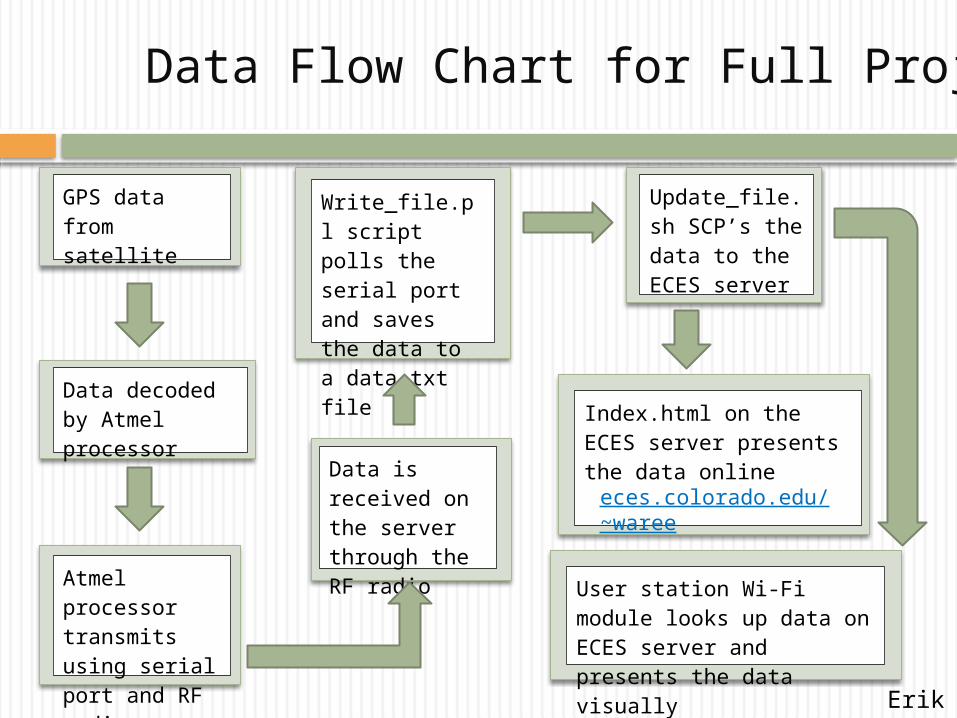
GPS data from satellite
Data decoded by Atmel processor
Atmel processor transmits using serial port and RF radio
Update_file.sh SCP’s the data to the ECES server
Write_file.pl script polls the serial port and saves the data to a data.txt file
Data is received on the server through the RF radio
Index.html on the ECES server presents the data online
User station Wi-Fi module looks up data on ECES server and presents the data visually
Data Flow Chart for Full Project
eces.colorado.edu/~waree
Erik

eces.colorado.edu/~waree
Erik

Software Description
Write_file.pl (perl)
Input: Polls the serial port and saves GPS data received Output: data.txt file, this script also executes write_file.sh
GPS_software.c (C-code)
This is on the Atmel processor, Input GPS data received through the SPI connection to the GPS module. Outputs: sends data to the LCD screen and sends it through the RS-232 port to the RF radio.
Update_file.sh (Expect)
Input: data.txt file on computer HD; Output: The ECES server using SCP protocol.
Index.html (JavaScript/HTML/XML)Handles the website JavaScript and html code, Input: looks up GPS data on ECES server; Output: display data on embedded Google map.
User_station.c (C-code)
Input: Looks up the GPS data on the ECES server and decoding it on the user-station processor; Output: visually displaying the data.
Erik
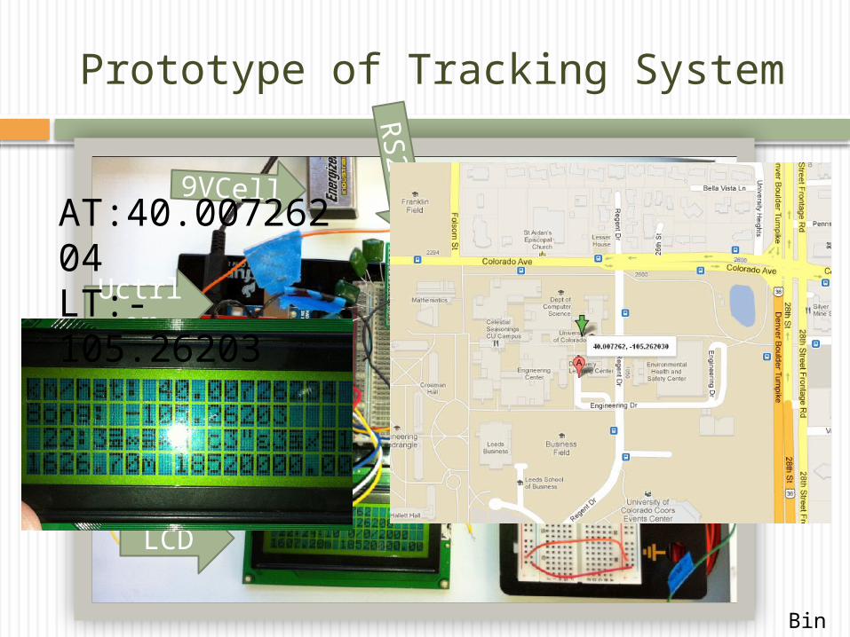
Prototype of Tracking System
LCD
GPS
Uctrler
RS232
GSM
9VCellAT:40.00726204LT:-105.26203
Bin

Software Decomposition
UART/RFInput:TTLsignal of ATLTOutput:Uart signal in RS232
LCDGPS-decode
Bin

RF module
1. Signal attenuate Significantly across building.
2. Consistent high power consumption
Bin

Small range:
R = 0.6 km
Large range:
R = 1.4 km
Bin

GSM (Global System for Mobile Communications)
Cellular-ADH8066
Function:SMS text messagesGSM/GPRSTCP/IP
Cost:50$/each
ADVANTAGE:
1. “Infinite” working range
2. Guaranteed Communication Quality
3. Easy to control by u-ctrller than mobile phone itself.
DISADVANTAGE:
Mainance Fee.(<30$/month)
Bin

Power Design(tracker)
Part Name Typical Current(mA)
GPS 70 70
Microcontroller(Active 8Mhz)
4.19 4.19
GSM(ADH8066)
2.5 (max:1A)
RF(X-tend pkg) 85(max:2A)
Total 96.69 159.19
1.The power of GSM is 34 times lower than RF we used.
2.Reduce the power of the system by 40%
3.Sleep mode significant reduce the power consumption Bin

Functionality of the PCB Board To transmit the current location to the
receiver at the main station to be uploaded to the website
•Atmega8-16PC•Voltage Regulators (NCP-1117-D, LP2985-33DBVR)•Serial Port•RS-232 (chip)•Clock (CSTCE16MOV53-R016MHz )•LCD screen
Parts List
David

Microcontroller
PC6 (RESET) 1
PD0 (RXD)2
PD1 (TXD)3
PD2 (INT0)4
PD3 (INT1)5
PD4 (XCK/T0)6
VCC 7
GND 8
PB6 (XTAL1/TOSC1)9
PB7 (XTAL2/TOSC2)10
PD5 (T1)11
PD6 (AIN0)12
PD7 (AIN1)13
PB0 (ICP)14
PB1 (OC1A)15
PB2 (SS/OC1B)16
PB3 (MOSI/OC2)17
PB4 (MISO)18
PB5 (SCK)19
AVCC 20
AREF 21
GND 22
PC0 (ADC0) 23
PC1 (ADC1) 24
PC2 (ADC2) 25
PC3 (ADC3) 26
PC4 (ADC4/SDA) 27
PC5 (ADC5/SCL) 28
U3
ATmega8-16PC
123456
AD
Header 6
12345678
IOL
Header 8
12345678
POWER
Header 8
123456789
10
IOH
Header 10GND
GND
AD4/SDAAD4/SDA
AD5/SCLAD5/SCL
+5V
VCCAREF
GND100pFC6
GNDVIN
+3V3
100nF
C4
1M
R3
GND
XTAL2 2Gnd1
XTAL1 3U5
ARD8ARD9
ARD11ARD12
ARD13
ARD10
ARD8ARD9
ARD11ARD12ARD13
ARD10
ARD2ARD1
•The GPS module plugs directly into the PCB board and is controlled by the Atmega microcontroller.
David

Powering the PCB Board
9V battery plugs into the Power Jack Voltage regulators convert the 9V battery
input to 5V and 3.3V output Green LED shows power is on
David

Interface1
2
3
4
5
6
7
8
9
11
10
J1
D Connector 9GND
.1uFC7
11
22
33
44
55
66
77
88 9 910
101111
12 1213
131414
15 1516
16U7
RS-232
100pF
C8Cap Pol1
RS-232_pin2
GND
RS-232_pin1
100pF
C9Cap Pol1
100pF
C10Cap Pol1
100pF
C11Cap Pol1
RS-232_pin4
RS-232_pin5
RS-232_pin1RS-232_pin2RS-232_pin3RS-232_pin4RS-232_pin5RS-232_pin6RS-232_pin7RS-232_pin8 RS-232_pin9
RS-232_pin10RS-232_pin11RS-232_pin12RS-232_pin13
RS-232_pin16
RS-232_pin14RS-232_pin15
RS-232_pin3 RS-232_pin6
GNDRS-232_pin16
+3V3
GND
GND
RS-232_pin15
12345678910111213141516
LCD
Header 16
GND
VCC
ARD12
ARD5ARD4ARD3ARD2
•The LCD screen will display the coordinates of the current bus location
•The RS-232 boosts the signal to 10 V and outputs to the transmitter via the serial port
David

PCB Layout
David

Future Work on PCB Design
Thoroughly check the board layout before sending the layout to Advanced circuits
Order all the components from Digikey Solder and mount components Testing for Milestone 1
David

USER station
•Display Bus Location•Time till bus arrive to the station

User station components
10 W solar panel LED map Arduino uno 74238 3- 8 decoder LCD WIFI-2.21 RN-131C Rechargeable Battery
Emile

Solar Battery
Emile

User station
Emile

Schematic View
Emile

LED Screen
Emile

Labor Division
Bin Wang On-bus system and WiFi Wireless communication and
telephone application design.
David Zigman On-bus PCB board design.
CTO
COO
CEO
CFO
Erik Ware Website design and working
with David on PCB board and software.
Emile Bahdi User station development.

Milestone 1&2 Deliverables
Milestone 1
•PCB board is functional and receiving GPS data
•Website can port test data into Google maps to display position
•PCB board is connected to RF radio and can send data to receiver
•Prototype of Wooden user station
•User station can look up correct Wi-Fi data and 4x16 decoder is properly connected
Milestone 2
•Completion of prototype system tested in line of site applications
•Route testing completed with RF radio and GPS coordinates for user station LED’s assigned
•User station built

Schedule & Time Management
Picture Generated by Microsoft® Office Project 2007

Schedule and Milestones
Jan.18 – Feb.2: Get group organized purchase essential hardware, get started and implement project detail plan.
Feb.2 – Feb.28: Finish building a portable GPS device(Bin) Build the prototype of user station(Emile,Bin)
Construct a website with CSS(Erik)Feb.28 – Mar.20: Communicate between terminal and server by WiFi-1(Bin)
Design and build on-bus PCB(Dave,Erik)Design and build user-station(Emile,Bin)Update website with real-time data(Erik)
Track main-campus bus without covering William Village and update websiteMar.20 – Apr.10: Communicate between terminal and server by WiFi(Bin)
Finish building user-station update data by WiFi(Emile,Bin)Embed website with Google Maps(Erik)PCB Board is working properly(Erik, David)
Track whole bus route and update location to website and user-station.Apr.11 – Apr.30: Improve redesign and focus on user application and do commercial advertisement(Erik,David,Emile,Bin).Apri.30 – May2: Summarizing documents and prepare for expo.May3: Win (Team:Winning)
Finished
Undergoing

Budget:
Name Quantity
Price($)
20 Channel EM-406A SiRF III Receiver with Antenna
1 59.95
GPS Shield 1 14.95
Arduino Uno SMD 3 29.95*3
XTend® RF Modems 1 Watt/900 MHz stand-alone radio modems
1 300 (Free)
Basic 16x2 Character LCD - Black on Green 1 13.95
Solar Panel - 10W 1 59.95
WiFly GSX Breakout 1 84.95
Nucasa O1/2X4-S S4S .5-Inch by 4 Flat Stock Lumber Sample
2 33.75*2
Poster and Documentation 100
PCB board 150
Interface, cables and tools 100
other 50
Total:
1091.1$
(Note: some components can be obtained from Capstone Laboratory
Name Quantity
Price($)
20 Channel EM-406A SiRF III Receiver with Antenna
1 59.95
GPS Shield 1 14.95
Arduino Uno SMD 3 29.95*3
XTend® RF Modems 1 Watt/900 MHz stand-alone radio modems
1 300 (Free)
Basic 16x2 Character LCD - Black on Green 1 13.95
Solar Panel - 10W 1 59.95
WiFly GSX Breakout 1 84.95
Nucasa O1/2X4-S S4S .5-Inch by 4 Flat Stock Lumber Sample
2 33.75*2
Poster and Documentation 100
PCB board 150
Interface, cables and tools 100
other 50
Name Quantity
Price($)
20 Channel EM-406A SiRF III Receiver with Antenna
1 59.95
GPS Shield 1 14.95
Arduino Uno SMD 3 29.95*3
XTend® RF Modems 1 Watt/900 MHz stand-alone radio modems
1 300 (Free)
ADH8066 Evaluation BoardADH8066 BreakoutADH8066 GSM module
1 56.03$19.95$49.95
Godaddy Domain Server 1 26.14
Solar Panel - 10W 1 59.95
WiFly GSX Breakout 1 84.95
Nucasa O1/2X4-S S4S .5-Inch by 4 Flat Stock Lumber Sample
2 33.75*2
Poster and Documentation 100
PCB board 150
Interface, cables and tools 100
other 50
Remaining Fund:631.2$

Question and Discussion
Your recommendation saves us money
Your advice saves us time
Presented by: Winning