Bus Station Infrastructure - Publications€¦ · • ensure best practice infrastructure design is...
58
6 Introduction 3 6.1 Overview of the Bus Station Infrastructure chapter 3 6.2 Purpose and objectives 3 6.3 Application of the Bus Station Infrastructure chapter 4 6.3.1 Intended audience 4 6.3.2 Application of the chapter 4 6.4 Principles of bus station planning 5 6.4.1 What is a station? 5 6.4.1.1 – Bus station categories 5 6.5 Bus station environment 6 6.5.1 Integration with land use 6 6.5.2 Accessibility and compliance 9 6.5.2.1 – Bus station operational considerations 9 6.5.2.2 – Demand analysis 9 6.5.2.3 – Other operational considerations for the planning and design of bus stations 10 6.5.3 Asset management 16 6.6 Bus station formation 18 6.6.1 Understanding station layouts 18 6.6.2 Bus station layouts 18 6.6.2.1 – Bus linear platform (mono- directional) 19 6.6.2.2 – Bus linear opposing platform (bi-directional) 20 6.6.2.3 – Bus linear staggered platform (bi-directional) 21 6.6.2.4 – Bus island platform—at-grade and grade-separated (mono-directional) 22 6.6.2.5 – Bus sawtooth platform (mono-directional) 23 6.6.2.6 – Rail and bus multi-modal platform 24 6.6.2.7 – Bus stop operation 26 6.6.2.8 – Design vehicles for bus stops 27 6.6.2.9 – Bus stop length requirements 28 1 Chapter 6 – Bus station infrastructure Contents Public Transport Infrastructure Manual, Department of Transport and Main Roads, March 2016
Transcript of Bus Station Infrastructure - Publications€¦ · • ensure best practice infrastructure design is...

6 Introduction 3
6.1 Overview of the Bus Station Infrastructure chapter
3
6.2 Purpose and objectives 3
6.3 Application of the Bus Station Infrastructure chapter
4
6.3.1 Intended audience 4
6.3.2 Application of the chapter 4
6.4 Principles of bus station planning 5
6.4.1 What is a station? 5
6.4.1.1 – Bus station categories 5
6.5 Bus station environment 6
6.5.1 Integration with land use 6
6.5.2 Accessibility and compliance 9
6.5.2.1 – Bus station operational considerations
9
6.5.2.2 – Demand analysis 9
6.5.2.3 – Other operational considerations for the planning and design of bus stations
10
6.5.3 Asset management 16
6.6 Bus station formation 18
6.6.1 Understanding station layouts 18
6.6.2 Bus station layouts 18
6.6.2.1 – Bus linear platform (mono-directional)
19
6.6.2.2 – Bus linear opposing platform (bi-directional)
20
6.6.2.3 – Bus linear staggered platform (bi-directional)
21
6.6.2.4 – Bus island platform—at-grade and grade-separated (mono-directional)
22
6.6.2.5 – Bus sawtooth platform (mono-directional)
23
6.6.2.6 – Rail and bus multi-modal platform
24
6.6.2.7 – Bus stop operation 26
6.6.2.8 – Design vehicles for bus stops 27
6.6.2.9 – Bus stop length requirements 28
1
?PART
Chapter 6 – Bus station infrastructure
Contents
Public Transport Infrastructure Manual, Department of Transport and Main Roads, March 2016

6.7 Functional design elements for bus stations
30
6.7.1 TransLink architectural theme 30
6.7.2 Arrangement of space 31
6.7.2.1 – Sequence of movement 31
6.7.2.2 – Circulation within public transport infrastructure
32
6.7.2.3 – Density of occupation 34
6.7.3 Identifiable station entry and exit 35
6.7.4 Passive surveillance 35
6.7.5 Climatic comfort and weather protection
36
6.7.6 Functionality and simplicity 36
6.7.7 Sustainable energy use and design
37
6.7.8 Operations and maintenance 38
6.7.9 Cultural and heritage places 38
6.8 Bus station components 40
6.9 Choosing station components 44
6.10 Technical details 57
Appendix 6-A 58
Typical single and double bus station platform arrangement plans
59
Typical single and double bus station shelter elevations
60
Typical bus driver facility 61
Typical secure bike storage facility 62
2
Chapter 6 – Bus station Infrastructure
Public Transport Infrastructure Manual, Department of Transport and Main Roads, March 2016Public Transport Infrastructure Manual, Department of Transport and Main Roads, March 2016

6.1 Overview of the Bus Station Infrastructure
chapter
The Bus Station Infrastructure chapter is a referenced component of the overarching Public Transport Infrastructure Manual (PTIM). This Bus station infrastructure chapter is to be used in conjunction with:
• PTIM, Background and application, which establishes the rules for application of the entire Public Transport Infrastructure Manual
• PTIM, Planning and design, which provides the overarching design guidelines and principles for public transport infrastructure across Queensland
• PTIM, Supporting access and infrastructure, which details the supporting access infrastructure required to support public transport stops, stations and related facilities
• PTIM, Branding, theming and signage, which provides branding, theming and signage that should be used for identifying coherent public transport infrastructure throughout Queensland.
For information on further resources to support the planning and design of bus stations, please refer to the PTIM, References and resources.
6. Introduction
6.2 Purpose and objective
The Bus station infrastructure chapter will inform infrastructure design by providing a clear and consistent set of principles and guidelines for bus stations across the TransLink network.
It will ensure that a high standard of infrastructure is planned and delivered to meet the needs and objectives of the TransLink passenger transport system and passenger expectation. Ultimately, high-quality and consistent infrastructure will provide customers with a transport system that is coherent, functional and encourages passenger use.
The objectives of this chapter are to:
• ensure best practice infrastructure design is applied across the TransLink network
• outline the preferred requirements for bus station design
• detail requirements for compliance with relevant standards and regulations
• ensure the delivery of high-quality public transport infrastructure
• ensure the delivery of accessible infrastructure.
3
Chapter 6 – Bus station infrastructure
Public Transport Infrastructure Manual, Department of Transport and Main Roads, March 2016
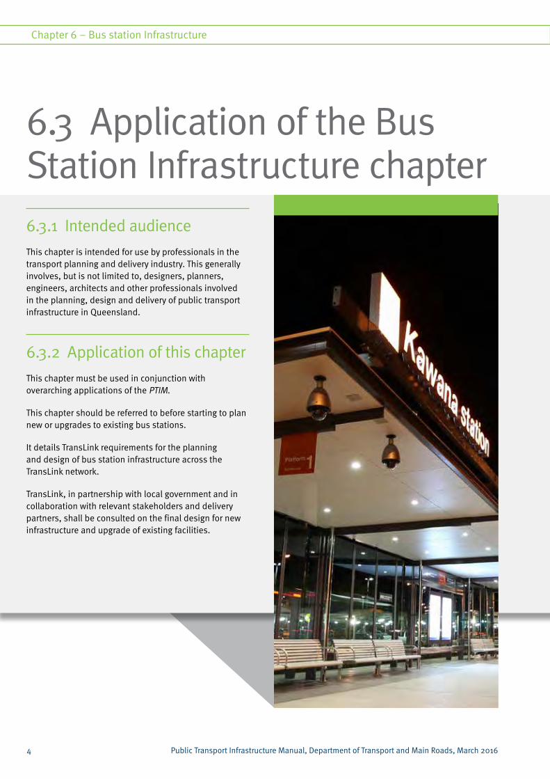
6.3.1 Intended audience
This chapter is intended for use by professionals in the transport planning and delivery industry. This generally involves, but is not limited to, designers, planners, engineers, architects and other professionals involved in the planning, design and delivery of public transport infrastructure in Queensland.
6.3.2 Application of this chapter
This chapter must be used in conjunction with overarching applications of the PTIM.
This chapter should be referred to before starting to plan new or upgrades to existing bus stations.
It details TransLink requirements for the planning and design of bus station infrastructure across the TransLink network.
TransLink, in partnership with local government and in collaboration with relevant stakeholders and delivery partners, shall be consulted on the final design for new infrastructure and upgrade of existing facilities.
6.3 Application of the Bus Station Infrastructure chapter
4
Chapter 6 – Bus station Infrastructure
Public Transport Infrastructure Manual, Department of Transport and Main Roads, March 2016Public Transport Infrastructure Manual, Department of Transport and Main Roads, March 2016

6.4 Principles of bus station planning
Bus station category Description
Standard bus station • Provide access to beginning and end of trip movement from multiple services
• Typically not intended for interchanging between modes
Intra-modal bus station • Destination or departure point for high-priority services
• Key bus-to-bus interchange points in the network
• Located on two or more bus corridors
Multi-modal station • Provide transfers between different modes
• Serve significant catchment areas
• Where two or more public transport corridors come together with different modes
Contact TransLink for confirmation and assistance with determining the hierarchy and category of station infrastructure.
6.4.1 What is a station?For the purpose of this chapter, a bus station is defined as:
‘a high-quality passenger transport facility that acts as a central departure and/or destination point to accommodate high passenger volumes’.
Bus stations provide passengers with the key point of connection between transport services and a desired destination (or transfer point en route to a destination). Stations are normally located on corridors with high-frequency services and can be located from outer-suburban areas to inner-city areas.
Stations generally serve key catchment areas such as commercial and business districts and may contain a moderate to very high level of supporting infrastructure (for example, quality footpaths, kiss ‘n’ rides, public amenities, cycle amenities and park ‘n’ rides).
6.4.1.1 Bus station categories
TransLink has categorised bus stations based on infrastructure function and configuration. These categories must work in conjunction with the public transport infrastructure hierarchy in the PTIM, Public Transport Infrastructure Planning and Design. This will establish infrastructure hierarchy and function based on its locality.
Table 6.1: Provides a brief description of the types of bus stations.
5
Chapter 6 – Bus station infrastructure
Public Transport Infrastructure Manual, Department of Transport and Main Roads, March 2016

Integration with land use is critical for all public transport infrastructure including bus station infrastructure, particularly in order to adequately cater for customers needs, ensures community access to services and contributes to reducing dependency on car.
While other factors such as operational capacity and network characteristics influence the functionality of public transport infrastructure, ultimately the location is the key driver for passengers using the facility.
The majority of locality factors (for example, population projections, demographics, major attractors) for public transport infrastructure are led by the relevant land use plan for the location. This could include:
• regional plans
• local government land use plans
• transport strategies and plans
Reference should also be made to the Queensland Government’s development assessment processes and systems.
The overarching design guidelines within the PTIM need to be applied giving consideration to site-specific characteristics to create an attractive, seamless integration with the surrounding environment.
In some cases, major public transport infrastructure (such as bus stations) is an integral part of supporting economic development of urban centres, and supports increased densities by encouraging transit-oriented developments.
The proximity of transport facilities with complementary land use developments is vital, as urban consolidation is necessary for achieving increased public transport patronage and therefore justifying high-frequency services.
6.5 Bus station environment
6.5.1 Integration with land use
6
Chapter 6 – Bus station Infrastructure
Public Transport Infrastructure Manual, Department of Transport and Main Roads, March 2016Public Transport Infrastructure Manual, Department of Transport and Main Roads, March 2016

7
Chapter 6 – Bus station infrastructure
Public Transport Infrastructure Manual, Department of Transport and Main Roads, March 2016

Figure 6.1 – Locality guidance examples for station facilities
The following principles should be applied to the planning and design of bus station infrastructure:
• stakeholder engagement: partnering with stakeholders to support transit-oriented development opportunities
• land use planning: design is appropriate to surrounding community and considers potential future densities and land uses
• catchment area: analyse the catchment area to inform existing and potential passenger volumes
• permeability: ensure there is high quality, legible access between the surrounding environment and the transport facility as per the access hierarchy, including pedestrian connectivity between activity nodes and the public transport station
• infrastructure footprint: the physical and operational footprint impacts of station facilities are optimised (for example, vehicle access, stormwater runoff catchments)
• safety and security: station is located to promote customer safety and security, as well as minimise opportunity for criminal or terrorism activity.
8
Chapter 6 – Bus station Infrastructure
Public Transport Infrastructure Manual, Department of Transport and Main Roads, March 2016Public Transport Infrastructure Manual, Department of Transport and Main Roads, March 2016

6.5.2 Accessibility and compliance
TransLink requires that the relevant standards and guidelines for disability access are followed, along with the engagement of relevant disability reference groups, where required.
The legislative requirements of the Commonwealth Disability Discrimination Act 1992 (DDA), sets out the responsibilities of the department with regards to access to public transport, with the specifics and details given in the Disability Standards:
• Disability Standards for Accessible Public Transport 2002 (Transport Standards)
• Disability (Access to Premises – Buildings) Standards 2010 (Premises Standards)
6.5.2.1 Bus station operational considerations
The design of public transport infrastructure needs to consider current and future capacity requirements.
The project scoping for public transport infrastructure should determine the timeframe to be considered in planning and design (for example, should 10, 20 or 30 year demand forecasts be used to inform facility design?). Depending on the site consideration and long-term public transport network plans, planning should consider provision for future expansion to increase capacity.
6.5.2.2 Demand analysis
Capacity requirements should be determined early in the planning phase and give consideration to:
• future patronage and service growth
• future transport network and corridor connections
• demographics, including surrounding land use in the vicinity of the facility.
In determining future patronage and service growth the following factors should be considered:
• baseline daily and/or peak volumes (includes passengers and/or vehicles)
• any forecast future daily volume (includes passengers and/or vehicles)
• other volume-related demand factors, including:
– length and scale of peak demand
– breakdown between flows associated with boarding and alighting
– timing factors, including whether it coincides with other peaks in the surrounding area
– number of peak periods per day per direction
– likely directional travel mode-share
• special needs demand, including:
– potential volumes of special needs users, disability groups, schools
– potential for land use scale, intensity or typology change.
TransLink can provide basic information, such as:
• existing patronage
• targets and forecast demand
• volume and frequency of current and future services for the location or corridor
• previous performance against reliability measures such as on-time running.
In some cases, additional counts, surveys or demand forecasts may need to be undertaken due to the absence of data. TransLink should always be consulted regarding appropriate demand identification methodologies and data validity.
For further information in determining pedestrian capacity and Levels of Service (LOS) requirements refer to PTIM, Planning and Design chapter 2.4.2.3 – Density of occupation.
9
Chapter 6 – Bus station infrastructure
Public Transport Infrastructure Manual, Department of Transport and Main Roads, March 2016

6.5.2.3 Other operational considerations for the planning and design of bus stations
There are numerous factors that need to be considered when planning bus station infrastructure. Table 6.2 summarises these issues and should be used as a checklist to ensure all the relevant considerations are included in the planning and design of new infrastructure.
10
Chapter 6 – Bus station Infrastructure
Public Transport Infrastructure Manual, Department of Transport and Main Roads, March 2016Public Transport Infrastructure Manual, Department of Transport and Main Roads, March 2016

Factors influencing planning and design
What to consider
Land availability • Footprint - Public transport infrastructure should not consume more space than needed for effective operations.
• Land constraints - Design needs to consider land constraints in determining size, configuration and function of the infrastructure. Where land is available (for example greenfield sites) it should be preserved to provide short and long-term demand. Consideration should also be made for the use of suitable brownfield sites particularly where land is the property of the State.
• The location of the facility should ideally also consider on-street designs where the station forms part of the normal main street setting in a city or town centre, particularly where this offers significant operational benefits for customer and operator.
Surrounding land use and attractors
• Future land use - Consider future land use and demographics in determining capacity requirements and design.
• Attractors - Consider adjacent and nearby attractors in determining capacity. Other capacity factors (such as network and service operations, events) should also be considered.
• Development or redevelopment opportunities created or enhanced by a bus station facility.
Service frequency • Frequency - The peak and off-peak frequency of services needs to be considered.
• Demand - Patronage increases should be estimated to assist in determining the possible life of the facility. Forecast patronage increases will require public transport facilities to be able to accommodate multiple services at higher frequencies. For example, bus stations will require an adequate number of bus bays to minimise delay to services using the facilities.
• Access considerations - Cycle parking and kiss ‘n’ ride bays will need to consider future demand requirements.
Fare collection • Fare collection considerations - The method of fare collection affects operational capacity of public transport facilities. For example, prepaid ticketing procedures enable faster boarding, reduced dwell times and allow greater person throughput.
• Pre-paid fare collection - Where pre-boarding fare collection is applicable, this needs to be included in the design. This could include pre-paid ticketing systems, especially those with high level-of-service. The provision of ticketing systems will be determined by facility layout, size, public comfort and level-of-service requirements, and revenue protection strategies. The facility layout must consider the appropriate location of the Paid/Unpaid threshold (position of fare collection barriers-gates) as part of ensuring sufficient and safe circulation and queuing of passengers particularly in peak operational periods.
Contact TransLink for preferred fare payment options.
Table 6.2: Operational considerations for planning and designing bus station infrastructure
11
Chapter 6 – Bus station infrastructure
Public Transport Infrastructure Manual, Department of Transport and Main Roads, March 2016
Factors influencing planning and design
What to consider
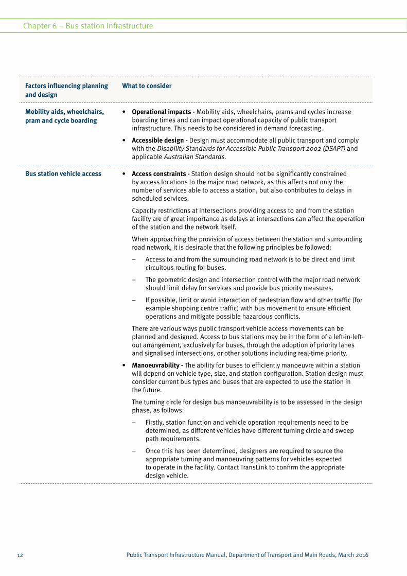
Mobility aids, wheelchairs, pram and cycle boarding
• Operational impacts - Mobility aids, wheelchairs, prams and cycles increase boarding times and can impact operational capacity of public transport infrastructure. This needs to be considered in demand forecasting.
• Accessible design - Design must accommodate all public transport and comply with the Disability Standards for Accessible Public Transport 2002 (DSAPT) and applicable Australian Standards.
Bus station vehicle access • Access constraints - Station design should not be significantly constrained by access locations to the major road network, as this affects not only the number of services able to access a station, but also contributes to delays in scheduled services.
Capacity restrictions at intersections providing access to and from the station facility are of great importance as delays at intersections can affect the operation of the station and the network itself.
When approaching the provision of access between the station and surrounding road network, it is desirable that the following principles be followed:
– Access to and from the surrounding road network is to be direct and limit circuitous routing for buses.
– The geometric design and intersection control with the major road network should limit delay for services and provide bus priority measures.
– If possible, limit or avoid interaction of pedestrian flow and other traffic (for example shopping centre traffic) with bus movement to ensure efficient operations and mitigate possible hazardous conflicts.
There are various ways public transport vehicle access movements can be planned and designed. Access to bus stations may be in the form of a left-in-left-out arrangement, exclusively for buses, through the adoption of priority lanes and signalised intersections, or other solutions including real-time priority.
• Manoeuvrability - The ability for buses to efficiently manoeuvre within a station will depend on vehicle type, size, and station configuration. Station design must consider current bus types and buses that are expected to use the station in the future.
The turning circle for design bus manoeuvrability is to be assessed in the design phase, as follows:
– Firstly, station function and vehicle operation requirements need to be determined, as different vehicles have different turning circle and sweep path requirements.
– Once this has been determined, designers are required to source the appropriate turning and manoeuvring patterns for vehicles expected to operate in the facility. Contact TransLink to confirm the appropriate design vehicle.
12
Chapter 6 – Bus station Infrastructure
Public Transport Infrastructure Manual, Department of Transport and Main Roads, March 2016Public Transport Infrastructure Manual, Department of Transport and Main Roads, March 2016

Factors influencing planning and design
What to consider
Bus station vehicle access (continued)
– The manoeuvring requirements should be overlayed and incorporated into the preferred station formations. Refer to relevant standards for bus turning circle and manoeuvrability requirements.
TransLink and relevant stakeholders will determine the stop configuration to be used at particular bus stations.
Stations that adopt an independent bus stop configuration need to allocate sufficient distances between stops to allow vehicles to efficiently manoeuvre between stops.
For bus stations with low speed environments, TransLink recommends that the turning and manoeuvring speeds be restricted to 15 kilometres per hour.
Station design must not require buses to reverse when manoeuvring into and out of stops. Forward direction in and out of a bus stop is the required outcome.
Speed humps are not preferred along TransLink bus routes. Where they are absolutely necessary, they are to be designed as an approved flat top speed hump. TransLink should be consulted when speed humps are considered for inclusion along TransLink bus routes and within facilities.
Pedestrian crossings • Type of crossing - At-grade pedestrian crossings can affect the operating capacity of the bus station. Conflicts between pedestrians and general vehicle traffic should be avoided where possible to promote efficient operations and reduce the risk of accidents.
Grade-separated pedestrian crossings should be provided at all high-volume stations with the use of stairs, escalators, ramps, lifts and/or bridges. The use of extensive ramp systems is not preferred as they can be too onerous for some customers, and in those cases lifts are the preferred option to meet disability access requirements.
Medium and lower volume stations that do not have a high-speed vehicle through-lane, but a low-speed single passing lane, may include at-grade pedestrian crossings at specific locations. The crossings are to be well signed and marked, have good sightlines for pedestrians and bus operators, include kerb ramps, and be located where there are low vehicle speed limits. Signalised crossings may also be considered but are subject to site-specific review.
• Connectivity - All pedestrian crossings should have clear and direct access to supporting infrastructure and surrounding facilities. The development of grade-separation should be carefully planned and incorporated in the early stages of the development planning. Where possible, the grade-separated structure should be integrated into the primary facility structure in order to minimise passenger travel.
13
Chapter 6 – Bus station infrastructure
Public Transport Infrastructure Manual, Department of Transport and Main Roads, March 2016

Factors influencing planning and design
What to consider
Bus boarding and alighting • Inclusive design - Low-floor fully-accessible buses generally reduce loading times, particularly in situations where a high percentage of passengers (such as people with disabilities, the elderly, people with prams and people with shopping or bulky goods) benefit from the easier vehicle access.
• All new public transport vehicles are required to comply with Disability Standards for Accessible Public Transport 2002 (DSAPT) and applicable Australian Standards.
• Mobility aids, wheelchairs and prams can have implications for loading times and potentially decrease the operational capacity of a station. However, it is imperative that stations are designed to accommodate all public transport users and ensure dignified and equitable access to all members of the community.
Platform and access area design
• Design space - Typically, platform areas and access paths, during peak periods, should be LOS C. Further guidance is available in John J. Fruin’s Pedestrian Planning and Design publication. Seating and waiting areas should be separated so that they do not interfere with boarding and alighting, facility entrances and exits, information points or other pedestrian circulation points.
Given the typical LOS C requirements, platform widths and lengths will vary depending on a range of design criteria including:
– the type and size of facility layout (for example in some cases buses will board from the front end of the platform in a lead stop situation, and others from independent stops, warranting separate design considerations for queuing and waiting passengers)
– the anticipated peak public demand (that is, numbers of passengers boarding and alighting)
– the type and size of vehicle and stopping arrangement
– the number of services expected to utilise the facility
– additional capacities to cater for missed headways.
• Personal comfort - Platform and access areas should be designed to be within the range of personal comfort during peak periods. The loading area must accommodate passenger movements when waiting, queuing and accessing services. Passengers boarding and alighting should not inhibit waiting passengers. Sufficient space also needs to be provided for passengers to move to and away from loading and waiting areas.
• Inclusive - All public transport infrastructure must be designed to accommodate all public transport users and comply with relevant access and design standards.
14
Chapter 6 – Bus station Infrastructure
Public Transport Infrastructure Manual, Department of Transport and Main Roads, March 2016Public Transport Infrastructure Manual, Department of Transport and Main Roads, March 2016

Factors influencing planning and design
What to consider
Bus layovers and driver facilities
• Efficiency - The provision of bus layover facilities, or bus holding zones, at stations enables buses to wait until required to commence a new service. This has the potential to allow more efficient bus operations by decreasing the number of trips between the depots and operating services, and minimise dead running.
Determining the required number of bus layover bays will generally be dependent on the proposed bus operations and types to be held at the particular station. TransLink will determine the number of spaces required, in consultation with bus operators, during the planning stage of a station.
• Amenities - Depending on service scheduling, bus driver amenities (meal rooms and toilets) may need to be provided at stations that have a significant number of terminating services. The size of these facilities should align with the required quantity of bus layover services and bays. The structure must complement other components of the station and be located in a discrete location (that is, in close proximity to bus layover areas) to provide efficient driver access.
• Layover often may need to be located off-site to facilitate compactness of station design and integration with adjacent/surrounding land uses. TransLink should give guidance on proximity, management and reliable access paths for off-site layover. Safe movement of drivers to and from layover and facilities needs to be planned and designed for.
Access infrastructure • High-quality access infrastructure - Planning and design should consider how passengers will access the infrastructure, and incorporate appropriate access facilities and infrastructure. For detailed guidance refer to the PTIM, Supporting access infrastructure chapter.
15
Chapter 6 – Bus station infrastructure
Public Transport Infrastructure Manual, Department of Transport and Main Roads, March 2016

6.5.3 Asset managementBus stations are major elements of passenger transport infrastructure and they need to be managed and maintained to sufficient operational conditions suitable for passenger comfort and safety.
The station components need to be maintained and managed on an ongoing basis to ensure the effective operation of a facility. The framework for how a facility will be managed after the delivery of infrastructure needs to be considered within the planning and design process.
The following must be considered when planning and designing bus station facilities:
• the general requirements for durability, cleaning and maintenance schedules of infrastructure components
• surveillance and access control of the facility
• cost-effectiveness, commonality and replacement of components
• approved suppliers of the materials and components
• access to water, electricity and other resources
• general operating costs (such as electricity, water and staff)
• statutory requirements for buildings and facilities
• requirements for staff.
The above is not a definitive list and other considerations may be required depending on site-specific circumstances.
Relevant operational stakeholders should be engaged in the planning and design process to ensure that the requirements of asset management by operators and/or owners have been considered. All components of bus station infrastructure should use materials and finishings consistent and compatible with existing infrastructure and of an approved standard. In consultation with relevant operating and maintenance stakeholders, detailed maintenance manuals should be developed for all components and operation schedules within a station facility. These should be prepared as a part of the station project.
16
Chapter 6 – Bus station Infrastructure
Public Transport Infrastructure Manual, Department of Transport and Main Roads, March 2016Public Transport Infrastructure Manual, Department of Transport and Main Roads, March 2016

17
Chapter 6 – Bus station infrastructure
Public Transport Infrastructure Manual, Department of Transport and Main Roads, March 2016

6.6 Bus station formation
6.6.1 Understanding station layouts
This section provides schematic station layout arrangements that can be used as a starting point in the early station planning and design phase. The schematic layouts can be configured to meet site-specific constraints and operational requirements.
With each site having unique characteristics, a site-specific response needs to consider:
• the surrounding environment and land use
• functional and operational capacity requirements
• surrounding catchment demand from the wider transport network.
Station design shall be undertaken in conjunction with TransLink and key stakeholders.
6.6.2 Bus station layouts
TransLink has defined a range of generic bus station layouts to suit the needs of both passenger and public transport vehicle requirements. Each layout defined in this section would need to be tailored to meet operational and site requirements for specific stations. The details depicted in the station layout drawings such as bus layovers, crossings, amenity facility locations, etc., aim to represent possible best practice outcomes; however, not all stations will be able to achieve the depicted desired outcomes given site constraints.
In addition to the bus station layout itself, a range of supporting infrastructure (for example, pedestrian and cycle components, kiss ‘n’ ride, and park ‘n’ ride) needs to be incorporated to complement station functionality. Refer to the PTIM, Supporting access infrastructure.
18
Chapter 6 – Bus station Infrastructure
Public Transport Infrastructure Manual, Department of Transport and Main Roads, March 2016Public Transport Infrastructure Manual, Department of Transport and Main Roads, March 2016

6.6.2.1 Bus linear platform (mono-directional)
The layout is suited to:
• standard stations or intra-modal stations with intended transferring between services
• linear sites with reasonable length and adequate footprint width
• sites with vehicle access and egress locations at either end of the platforms
• stations located at-grade with lower speed limits and access from the surrounding road network
• a greater proportion of high frequency services compared to local and feeder services.
This layout comprises linear bays and passenger loading platforms located on either side of a through carriageway.
Buses run through the station in a single direction and use one entry and exit point. In most cases, depending on site constraints, the platform waiting areas for each bay (including shelters) will run parallel and have the same directional facing aspect.
Platform areas need adequate room for pedestrian movement, queueing and waiting areas. Pedestrian crossings will be positioned behind vehicle movements to minimise impact on station operations and ensure pedestrian safety.
Station design should use transparent and lightweight structures to promote passive surveillance.
Buses can either pull up at independent stops along the platform, or a lead-stop approach can be implemented.
Figure 6.2 – Bus linear platform schematic layout (mono-directional)
19
Chapter 6 – Bus station infrastructure
Public Transport Infrastructure Manual, Department of Transport and Main Roads, March 2016

6.6.2.2 Bus linear opposing platform (bi-directional)
The layout is suited to:
• linear sites with reasonable length and adequate width
• sites with vehicle access and egress locations at either end of the platforms
• predominantly dedicated bus priority corridors (that is, transitways, busways) that may feature grade-separation where high-frequency services operate
• bus routes passing through stations with no intended transferring between services.
Linear bi-directional stations consist of a linear formation with bays and platforms located on either side of a through carriageway and services running in opposing directions.
Bi-directional platforms will face and run parallel to each other, with entry and exit at both ends. These bus stations are predominantly located on high-frequency services corridors and tend to be grade separated.
Pedestrian access will primarily be through grade-separated measures such as stairs, lifts and pedestrian overpasses.
Pedestrian access will generally require a site-specific response due to the lead-stop approach commonly used.
Pedestrian access will generally be located at the back end of the platform for the morning peak inbound services to assist with efficient passenger movements. This layout can offer high passive surveillance between platforms when designed with a transparent median barrier, whilst deterring pedestrians from crossing inappropriately.
Figure 6.3 – Bus linear opposing platform (bi-directional)
20
Chapter 6 – Bus station Infrastructure
Public Transport Infrastructure Manual, Department of Transport and Main Roads, March 2016Public Transport Infrastructure Manual, Department of Transport and Main Roads, March 2016

6.6.2.3 Bus linear staggered platform (bi-directional)
The layout is suited to:
• linear sites with ample length and limited width
• sites with vehicle access and egress locations at either end of the platforms
• typically high-frequency services
• stations located at-grade and/or with access from surrounding road network
• bus routes not intended for high volume passenger transfers between services.
This station layout consists of an elongated linear platform arranged in a staggered configuration, and is suitable where space is limited.
The staggered platforms consist of a mid-block chicane so that the overall cross section requires three lanes instead of the more conventional four lanes. This station is suited to buses running in a bi-directional manner along a corridor, while a lead-stop approach is commonly employed.
Pedestrian access is typically at-grade while crossings are to be located directly in the middle of the station layout to ensure convenient and safe passenger movements. Effective passive surveillance is considered to be more difficult to achieve at these stations because of the greater distance between the ends of opposite platforms.
It should be noted that this layout is not compatible with LRT station operation.
Figure 6.4 – Bus linear staggered platform (bi-directional)
21
Chapter 6 – Bus station infrastructure
Public Transport Infrastructure Manual, Department of Transport and Main Roads, March 2016

6.6.2.4 Bus island platform — at-grade and grade-separated (mono-directional)
The layout is suited to:
• standard stations or intra-modal stations requiring transfers
• feeder and terminating services where buses can easily access bus layover areas
• rectangular sites with ample width and limited length
• sites with limited or fixed vehicle access and egress locations to surrounding road networks
• a high proportion of local, feeder and terminating services, particularly for services needing to manoeuvre through the station.
This layout consists of an island platform where passenger platform areas are located in the middle of the station with bus stops located around the island perimeter. Independent stops, as opposed to a lead-stop approach, are generally used.
Depending on the location of vehicle access and egress to the surrounding road network, buses circulate in a single direction around the island platform and allow boarding from both sides.
Depending on site requirements and number of services, pedestrian access can be provided with at-grade or grade-separated treatments. The layout of the island platform provides for a central waiting point for passengers that enhances personal safety with optimal passive surveillance, maintains simplicity, and provides for convenient interchanging if required.
Figure 6.5 – Bus island platform at-grade (mono-directional)
Figure 6.6 – Bus island platform grade-separated (mono-directional)
22
Chapter 6 – Bus station Infrastructure
Public Transport Infrastructure Manual, Department of Transport and Main Roads, March 2016Public Transport Infrastructure Manual, Department of Transport and Main Roads, March 2016

6.6.2.5 Bus sawtooth platform (mono-directional)
The layout is suited to:
• compact site footprints with inadequate length to provide the appropriate number of vehicle bays in a linear arrangement
• sites with limited access and egress locations to surrounding road networks
• a high proportion of local feeder or terminating services compared to limited or no line haul services operating
• standard stations or intra-modal stations where passenger interchange occurs in significant volumes.
This layout consists of angled bus bays with passenger loading platforms located as either an island or linear loading style arrangement where buses manoeuvre forward into and out of bays. Bus circulation will be determined by the location of stops (around the island or outer perimeter) and access options from the surrounding road network.
Passenger access will predominantly be provided at-grade due to the slower speeds of buses manoeuvring in and out of the station.
Pedestrian crossings should be located at safe and convenient access points depending on the surrounding attractors and direction of bus circulation. Specific shelter design should be taken into consideration to ensure adequate coverage due to the unique platform layout.
It should be noted that the sawtooth station layout has the potential for increased manoeuvring times as well as posing safety risks for sightlines of bus operators and pedestrians.
Providing adequate shelter coverage at this type of station layout can be more complicated than more conventional layouts due to the nature of the sawtooth bays.
This station type is TransLink’s least preferred station layout and should only be adopted if other layouts are unable to meet the site requirements.
Figure 6.7 – Bus sawtooth platform (mono-directional)
23
Chapter 6 – Bus station infrastructure
Public Transport Infrastructure Manual, Department of Transport and Main Roads, March 2016

6.6.2.6 Rail and bus multi-modal platform
The layout is suited to:
• multi-modal stations offering complementary bus and rail transfers
• bus feeder or high frequency services
• sites with larger land area availability and/or significant surrounding attractors
• good access to rail corridor and surrounding road network (or dedicated bus corridors).
Any of the previous layouts can be used as a basis to design a multi-modal facility for bus passengers transferring to rail.
Bus and rail platforms need to be located to allow seamless transfer between different services. Platforms should be adjacent to, and preferably parallel to, one another to minimise connection distances, maintain easy navigation and enhance passive surveillance.
Successful integration with regard to connectivity will give the impression of one integrated station rather than two that have been retro-fitted. While the figure below shows a layout with both bus and rail stations at the same grade, multi-level station layouts can be explored (such as integrating bus station platforms above rail station platforms).
Ticketing and information facilities are to be easily accessed from station entry points and areas used to transfer between services. Platforms supporting peak inbound services should be given preference for all general station facilities (such as ticket window facilities and toilets).
Pedestrian access around the station should be through correct layout of crossings and/or grade-separated solutions (stairs, overpasses, lifts) where required.
Figure 6.8 – Bus linear opposing platform (bi-directional)
24
Chapter 6 – Bus station Infrastructure
Public Transport Infrastructure Manual, Department of Transport and Main Roads, 2015Public Transport Infrastructure Manual, Department of Transport and Main Roads, March 2016

25
Chapter 6 – Bus station infrastructure
Public Transport Infrastructure Manual, Department of Transport and Main Roads, 2015

6.6.2.7 Bus stop operationThe operation type influences the length of the bus stop zone/bay and the requirements of the bus zone and bus area. Bus stop operation types are described in Table 6.3.
Unless nose to tail operations (that is, lead stop operation) have been specifically identified, independent stop configuration operations should be adopted for bus stop design purposes.
TransLink should be consulted on the preferred operation prior to commencing bus stop design.
Table 6.3: Bus stop operation type
Bus bay operation Description
Single bus • Accommodate at least a single bus manoeuvring
• Typical for low or moderate frequency bus services
Nose-to-tail/platooning at lead stop
• Single boarding point for customers where buses platoon behind each other
• Typical for high-frequency services services
• Minimum additional length per bus needs to be added for this type of manoeuvring to occur
Independent stop configuration
• Designed to address one or a pre-designated set of services
• Requires additional minimum length per bus to allow for efficient and safe independent manoeuvring
26
Chapter 6 – Bus station Infrastructure
Public Transport Infrastructure Manual, Department of Transport and Main Roads, March 2016Public Transport Infrastructure Manual, Department of Transport and Main Roads, March 2016

6.6.2.8 Design vehicles for bus stops
The current fleet in service in the TransLink network varies by operator across the state. Subtle differences in fleet dimensions are likely and need to be considered during the design of accessible bus stops.
For design purposes, a standard rigid bus is typically 12.5 metres in length. Other buses in use include 14.5 metre long rigid buses and 18 metre articulated bus, and 12.5 metre double-decker buses. An approximate width allowance is 3 metres and height 3.5 metres (4.5 metres for double-decker).
Bus door locations must be kept free from all roadside infrastructure. Signposts, trees, tree-grates, planter boxes/landscaping, electrical poles/posts, and other street furniture must be at least 600mm from the kerb, along the length of the bus stop area.
Table 6.4 illustrates the estimated door position (metres from the front of the bus) for the different bus types. This can be used to determine the required length of hardstand, and position of other bus stop components to ensure accessible boarding and alighting of passengers.
Table 6.4: Estimated bus door position
Typical bus and lengthEstimated door position (metres)
1 2 3 4 5 6 7 8 9 10 11 12 13 14 15 16 17 18
Rigid bus (12.5m)
Rigid bus (14.5m)
Articulated three door bus (18m)
Rigid bus double-decker (12.5m)
Source: Estimate based upon typical bus fleet dimensions provided by Brisbane City Council.
27
Chapter 6 – Bus station infrastructure
Public Transport Infrastructure Manual, Department of Transport and Main Roads, March 2016
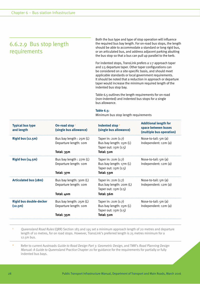
6.6.2.9 Bus stop length requirements
Both the bus type and type of stop operation will influence the required bus bay length. For on-road bus stops, the length should be able to accommodate a standard or long rigid bus, or an articulated bus, and address adjacent parking abutting the bus stop so that a bus can pull up parallel to the kerb.
For indented stops, TransLink prefers a 1:7 approach taper and 1:5 departure taper. Other taper configurations can be considered on a site-specific basis, and should meet applicable standards or local government requirements. It should be noted that a reduction in approach or departure taper would increase the minimum required length of the indented bus stop bay.
Table 6.5 outlines the length requirements for on-road (non-indented) and indented bus stops for a single bus allowance.
Table 6.5: Minimum bus stop length requirements
1 Queensland Road Rules (QRR) Section 183 and 195 set a minimum approach length of 20 metres and departure length of 10 metres, for on road stops. However, TransLink’s preferred length is 25 metres minimum for a 12.5m bus.
2 Refer to current Austroads Guide to Road Design Part 3: Geometric Design, and TMR’s Road Planning Design Manual: A Guide to Queensland Practice Chapter 20 for guidance for the requirements for partially or fully indented bus bays.
Typical bus type and length
On-road stop 1
(single bus allowance)Indented stop 2 (single bus allowance)
Additional length for space between buses (multiple bus operation)
Rigid bus (12.5m) Bus bay length : 25m (L) Departure length: 10m
Taper in: 21m (1:7) Bus bay length: 15m (L) Taper out: 15m (1:5)
Nose-to-tail: 5m (a) Independent: 12m (a)
Total: 35m Total: 51m
Rigid bus (14.5m) Bus bay length : 27m (L) Departure length: 10m
Taper in: 21m (1:7) Bus bay length: 17m (L) Taper out: 15m (1:5)
Nose-to-tail: 5m (a) Independent: 12m (a)
Total: 37m Total: 53m
Articulated bus (18m) Bus bay length: 30m (L) Departure length: 10m
Taper in: 21m (1:7) Bus bay length: 20m (L) Taper out: 15m (1:5)
Nose-to-tail: 5m (a) Independent: 12m (a)
Total: 40m Total: 56m
Rigid bus double-decker (12.5m)
Bus bay length: 25m (L) Departure length: 10m
Taper in: 21m (1:7) Bus bay length: 15m (L) Taper out: 15m (1:5)
Nose-to-tail: 5m (a) Independent: 12m (a)
Total: 35m Total: 51m
28
Chapter 6 – Bus station Infrastructure
Public Transport Infrastructure Manual, Department of Transport and Main Roads, March 2016Public Transport Infrastructure Manual, Department of Transport and Main Roads, March 2016

As noted in Table 6.5, additional length is required to accommodate multiple buses at the bus stop, either in nose-to-tail or independent operation.
The following formula can be used to calculate an initial bus stop bay length when considering a multiple bus operation. Calculated lengths should be confirmed through undertaking a vehicular swept path assessment to take into consideration other site characteristics (for example, narrower adjacent lane widths).
Length of bus bay = L + (BL + a) x (n - 1)
Where:
• ‘L’ is the bus bay length for a single bus
• ‘BL’ is the length of bus
• ‘a’ is the additional length for other bus stop operations
• ‘n’ is the number of buses
For on-road stops (as per Table 6.5):
The bus bay length (L) is:
• 25m for a 12.5m bus
• 27m for a 14.5m bus
• 30m for a 18m bus.
For Indented bus stops (as per Table 6.5):
The bus bay length (L) – based on a 1:7 approach taper and 1:5 exit taper – is:
• 15m for a 12.5m bus
• 17m for a 14.5m bus
• 20m for a 18m bus.
The additional length for other bus stop operations (a) is:
• 5m for nose-to-tail
• 12m for independent operations.
Example:
Two 12.5m rigid buses using an independent stop configuration. Stop area for a 12.5m bus is 25m and additional length for independent operations is 12m.
Therefore:
Length of bus bay = 25 + (12.5 + 12) x (2 – 1) = 49.5 metres.
29
Chapter 6 – Bus station infrastructure
Public Transport Infrastructure Manual, Department of Transport and Main Roads, March 2016

Ensuring that the arrangement of key components is correctly incorporated will contribute towards quality outcomes for the overall facility design.
Each of the following principles described in this section should be incorporated into the design of public transport infrastructure.
6.7.1 TransLink architectural theme Passengers find it easy to recognise, interpret and navigate public transport infrastructure.
Public transport infrastructure should be designed to:
• be legible within the built environment
• be contemporary
• have a consistent visual appearance
• address climatic conditions
Infrastructure is one of the most recognisable parts of the TransLink network. A consistent ‘look and feel’ across the network will increase passenger confidence, with customers having clear expectations. Design elements can be tailored to meet specific operational and functional requirements at individual sites, while still maintaining a consistent ‘look and feel’ across the network.
The TransLink architectural theme provides the framework for establishing a coherent network of public transport infrastructure across the state. Infrastructure planning and design should:
• reflect the relative importance of the infrastructure in the overall public transport hierarchy
• comply with network standards for components such as structures, pavements, signage and way-finding
• be based on the use of modular components to reduce cost, as well as for ease of maintenance and future capacity enhancement
• use common materials that emulate a lightweight appearance to deliver a modern, open and safe environment
• comply with applicable standards and regulations Including:
– Disability Standards for Accessible Public Transport 2002 (Cth)
– relevant Australian Standards.
6.7 Functional design elements for bus stations
30
Chapter 6 – Bus station Infrastructure
Public Transport Infrastructure Manual, Department of Transport and Main Roads, March 2016Public Transport Infrastructure Manual, Department of Transport and Main Roads, March 2016

6.7.2 Arrangement of space
Customers enjoy free flowing movement within the station.
Public transport infrastructure can include public and private spaces. Public spaces form the pathway from the point of entry to the point of departure.
Private spaces should not obstruct paths of travel, sightlines to points of entry, information and decision points, and waiting and seating areas. Private spaces can include:
• retail and commercial areas
• maintenance and management facility areas
• communications and electrical cupboards.
6.7.2.1 Sequence of movement
The layout of a transport facility should consider the sequence of public movement. Public movement is in response to the progressive sequence of actions and decision points along the path of travel. Movement should be in a forward direction from the entry to the platform, as illustrated in Figure 6.9.
Figure 6.9 – Sequence of movement
31
Chapter 6 – Bus station infrastructure
Public Transport Infrastructure Manual, Department of Transport and Main Roads, March 2016

6.7.2.2 Circulation within public transport infrastructure
Table 6.6: Principles of circulation
Type of circulation Principles
Direct circulation • Route between entry and boarding points should be as direct as possible.
• Minimise turns in the path of travel and avoid turns greater than 180 degrees.
• Changes of level should be through continuous straight flights of stairs or ramps and, if appropriate, escalators or lifts.
– If turning is required, landings are to be provided with necessary room for appropriate separation and manoeuvring, and
– Stairs circulating at 90-degree turns must adopt suitable measures to provide good sightlines for ascending and descending.
See Figure 6.10.
Cross-path circulation • Provide simple and clearly defined paths of travel that avoid conflict and maximise station capacity.
• Paths of travel should be clearly established to meet the requirements of passengers on the dominant side of the pathway, away from the opposite flow path.
• Avoid circulation systems that have people crossing the paths of others to access information, ticketing, amenities, platforms, ranks, seating, rubbish disposal and other requirements.
See Figure 6.11.
Left-hand circulation • Dominant movement pattern of pedestrians is based on the majority of travel undertaken on the left-hand side.
• Circulation within the facility (including around components and amenities) should follow this convention for predictability and efficiency.
Vertical circulation • Vertical circulation components such as stairs, ramps, lifts and escalators should be assembled together centrally.
• Centralised location of components assists with convenient placement of public information.
• All access components must comply with the relevant Disability Standards.
32
Chapter 6 – Bus station Infrastructure
Public Transport Infrastructure Manual, Department of Transport and Main Roads, March 2016Public Transport Infrastructure Manual, Department of Transport and Main Roads, March 2016

Type of circulation Principles
Changing direction • Changes in direction within circulation should only occur where there is sufficient space to allow passengers to maintain a sense of direction (use of transparent materials to enable views is preferable).
• Appropriate space should be provided at information and decision points for people to avoid conflict with the flow path of travel to ensure comfortable and efficient movement.
Emergency evacuation circulation
• Emergency evacuation considerations, including appropriate circulation paths, exits and assembly points, should cater for the maximum volume of people using the facility at any one time.
• Effective signage and way-finding is a key consideration for public circulation in an emergency situation. This must be reviewed in the detailed design stage and receive approval by an emergency evacuation specialist.
• Facilities which are structurally at-grade, elevated or below grade present complex emergency and safety requirements that warrant project specific design investigation.
Note: The Premises Standards and the National Construction Code (NCC) including the Building Code of Australia (BCA) provide technical emergency and safety requirements for passenger transport facilities, as well as cross referencing to the relevant Australian Standards for design guidance.
Figure 6.11 – Cross-path circulation
Figure 6.10 – Direct circulation
33
Chapter 6 – Bus station infrastructure
Public Transport Infrastructure Manual, Department of Transport and Main Roads, March 2016

6.7.2.3 Density of occupation The density of passengers to be accommodated should be within the range of personal comfort, and passengers should experience modest restrictions without coming into undesirable contact with any person. The public level of service (LOS) classification ranges from LOS A to F (Fruin, 1978, Pedestrian Planning and Design). Level A is the least crowded environment and Level F is the most crowded environment (and hence most undesirable). TransLink requires that an acceptable LOS be achieved for pedestrian areas to ensure comfortable pedestrian densities are not compromised during peak periods.
The areas of pedestrian occupation which typically require a LOS design response include:
• waiting and queuing areas (including ticketing and information points such as information displays, fare machines, fare gates, and SACIDS )
• seating
• walkways or other areas of circulation
• stairways
• overpasses
• lifts
• ramps
• escalators and travelators.
Note that the suitable LOS for different pedestrian areas of a station will warrant a different level of area allocation per pedestrian (for example, the physical space of LOS C for stairways will be different from the LOS C for waiting areas). In addition to appropriate space allocation, all pedestrian areas of a station will comply with applicable Disability Standards.
For pedestrian horizontal travel (that is, walkways and overpasses) and platform waiting areas, TransLink typically prefers that a LOS C (between 0.65–0.9 square metres per person of personal space) be achieved as a minimum during peak periods.
However, this preference may be subject to change depending on station and service functional arrangements.
Figure 6.12 – Density of occupation
LOS C LOS F
34
Chapter 6 – Bus station Infrastructure
Public Transport Infrastructure Manual, Department of Transport and Main Roads, March 2016Public Transport Infrastructure Manual, Department of Transport and Main Roads, March 2016

6.7.3 Identifiable station entry and exit
Entry and exit points are clearly defined and highly legible to customers.
Clearly defined entry and exit points are essential; not only providing points of access, but also defining the station boundaries and where access infrastructure needs to link to the station from the surrounding built environment.
Design considerations should include provision of entry plazas, information areas, station concourse, ticket office or facility, and fare gates.
Figure 6.14 –
Passive surveillance
6.7.4 Passive surveillanceInfrastructure is designed to provide passive surveillance and deter undesirable behaviour.
The physical environment of public transport facilities must be designed to minimise the possibility of crime, property damage and anti-social behaviour associated with people gathering in public spaces. Creating defensible spaces that allow for surveillance from outside and within the facility will promote safe environments and will attract greater public use. Refer to the current version of the Queensland Government’s Crime Prevention Through Environmental Design (CPTED) guidelines.
Figure 6.13 – Identifiable entry/facility
35
Chapter 6 – Bus station infrastructure
Public Transport Infrastructure Manual, Department of Transport and Main Roads, March 2016

6.7.5 Climatic comfort and weather protection
Figure 6.15 – Climatic comfort and weather protection
Sun and weather protection is to be provided.
In developing the design of facilities the following should be considered:
• structures must provide sufficient physical width, length and height to achieve high-quality climatic comfort and weather protection for passengers to occupy this space
• passengers should be provided with appropriate protection with enclosed or covered station access points, public information and decision points, seating and waiting areas, and boarding and alighting areas
• consideration must be given to the management of sun, wind, rain, heat, glare and humidity.
An appropriate climate analysis should be included within the planning and design of public transport infrastructure to inform appropriate facility orientation and suitability for specific locations.
6.7.6 Functionality and simplicity
Maintain simplicity and provide a functional station design that passengers can easily interpret and use.
The design of structures, platforms, ranks, seating, signage, pavements and other components must be incorporated within the overall design process to achieve highly functional station design outcomes.
The design should provide a legible and pleasant environment that is uncluttered, with minimal concealed spaces.
36
Chapter 6 – Bus station Infrastructure
Public Transport Infrastructure Manual, Department of Transport and Main Roads, March 2016Public Transport Infrastructure Manual, Department of Transport and Main Roads, March 2016

6.7.7 Sustainable energy use and design
Sustainability is to be considered in developing all public transport infrastructure.
Design and delivery of public transport infrastructure will focus on sustainability through:
• facility design that is fit for purpose now and into the future, and adaptable to change
• contributing to attractive community spaces and a local sense of place
• commitment to a low environmental footprint and whole-of-life approach through all design, construction and maintenance activities
• increasing visibility of sustainable features, and undertaking a participatory approach to design to improve community awareness and support
Details of TransLink sustainability requirements are included in Table 6.7.
Table 6.7: Key environmental sustainability design considerations
Key sustainability Consideration
Requirement where possible
Water management • On-site rainwater collection and reuse
• On-site run-off treatment (that is, scrubbing using permeable surfaces, detention basins and swales)
• Local flooding mitigation and flow maintenance
Resource minimisation • Water - employ water-saving devices
• Energy - aim for energy-neutral infrastructure through minimisation of energy use and generation opportunities (for example, solar for feeding back into electrical supply)
• Materials - apply whole-of-life design approach—construction, operation, maintenance, cleaning, and decommissioning. Materials should favour renewables and recyclables
• Processes - avoid operational processes that generate waste, especially toxins and pollutants
37
Chapter 6 – Bus station infrastructure
Public Transport Infrastructure Manual, Department of Transport and Main Roads, March 2016

6.7.8 Operations and maintenance
The components and materials that make up a public transport facility should be durable and meet their intended operational requirements. For further details on requirements refer to 2.3.4 Asset Management section of the PTIM, Public Transport Infrastructure Planning and Design.
Key sustainability consideration
Requirement where possible
Habitat and physical environment
• Protect habitat (that is, space, physical elements such as tree hollows and burrows, movement paths)
• Maintain water flows to aquatic and other habitats
• Avoid acid sulphate soils
• Minimise fugitive emissions of air, surface and groundwater-borne pollutants
Social sustainability • Present minimal harm to employees or public
• Promote social justice, inclusion and equity
• Contribute to improving social capacity and community interaction
• Enhance community experience and integrate facilities with the surrounding environment to enhance economical viability and social benefits
6.7.9 Cultural and heritage places
Heritage values are protected in the upgrade and delivery of public transport infrastructure.
Existing sites may contain components or structures of cultural or heritage significance. Such sites may require particular investigation and attention in the facility design. For example, rail stations are commonly listed as having heritage significance and require careful consideration and approval with respect to structural design and modification. Sites with cultural features or significance may require permission or approval prior to commencement of any planning and design work. TransLink recommends an appropriate level of assessment is undertaken by an expert assessor.
38
Chapter 6 – Bus station Infrastructure
Public Transport Infrastructure Manual, Department of Transport and Main Roads, March 2016Public Transport Infrastructure Manual, Department of Transport and Main Roads, March 2016

39
Chapter 6 – Bus station infrastructure
Public Transport Infrastructure Manual, Department of Transport and Main Roads, March 2016

6.8 Bus station components
This section details the components that need to be included at bus stations. The use of quality components (including materials and furnishing) will support effective station operation by:
• providing a comfortable and safe passenger environment
• delivering robust infrastructure that minimises the need for maintenance.
All building and construction components of station design are to comply with relevant building codes and Australian Standard requirements.
TransLink in partnership with Local Government shall be consulted on infrastructure component inclusions for each facility.
The correct level of design components making up a facility will depend significantly on the role of the station in the TransLink network (that is, TransLink’s hierarchy of transport facilities).
These are detailed in Table 6.8 where:
• M is mandatory (component must be included)
• P is preferred (component will be included subject to site constraints)
• S is site-specific response (may be required depending on the station purpose and requirements).
40
Chapter 6 – Bus station Infrastructure
Public Transport Infrastructure Manual, Department of Transport and Main Roads, March 2016Public Transport Infrastructure Manual, Department of Transport and Main Roads, March 2016

Category Station component Facility requirements
Information and signage
Signage (includes all relevant station identification, supporting components or infrastructure, and wayfinding)
M
Stop identification sign M
Zone information M
Site-specific timetables with route destinations M
Public transport information (static timetables, locality maps, interchange information, other customer information)
M
Real-time passenger information P
Public transport next service information facility S
Park ‘n’ ride/kiss 'n' ride wayfinding signage S
Public address system (including hearing augmentation)
S
Accessibility
Surface transactions and access
Minimum boarding point, including TGSI M
Tactile Ground Surface Indicators (TGSIs) M
Pavements / hardstand area M
Kerbs M
Accessible clear path of travel M
Kerb ramps M
Ramp access S
Stairs and escalators S
Lifts and overpasses S
Table 6.8: TransLink required components.
41
Chapter 6 – Bus station infrastructure
Public Transport Infrastructure Manual, Department of Transport and Main Roads, March 2016

Category Station component Facility requirements
Supporting access facilities
Cycle parking / storage P
Park ‘n’ ride S
Kiss 'n' ride and taxi facilities P
Shelters M
Ticketing/information office S
Fare machine (AVVM) P
Public toilets S
Driver amenities S
Stop furniture
Shelters M
Seating and lean rails M
Rubbish bins M
Drinking fountain P
Security and safety
Security cameras * S
Emergency call points (must coincide with CCTV) P
Lighting (bright white) M
CPTED principles M
Fare collection
Ticketing / information office S
Fare machine (AVVM) P
Fare gates S
Optional enhancements
Context material Public art S
* Liase with TransLink on this requirement
42
Chapter 6 – Bus station Infrastructure
Public Transport Infrastructure Manual, Department of Transport and Main Roads, March 2016Public Transport Infrastructure Manual, Department of Transport and Main Roads, March 2016

Category Station component Facility requirements
Customer facilities Accessible toilet / public toilets S
Shopping trolley bay(s) / storage S
Commercial and ancillary services
Vending machine (third party) S
Customer wireless internet access solutions S
Advertising allowances P
ATM S
Retail S
Landscape treatments Landscape treatment P
Environmentally sustainable design initiatives
Energy-efficient applications P
Water-saving devices P
Renewable and recycled materials used for components
P
Air quality solutions (air pollution) S
Noise quality solutions (noise pollution) S
Operational facilities
Bus layover (bus holding zone) S
Driver layover amenities / storeroom S
Note: All components are to be compliant with applicable Disability and Australian Standards. TransLink, with the assistance of relevant stakeholders, will determine facility hierarchy and final components required at facilities.
43
Chapter 6 – Bus station infrastructure
Public Transport Infrastructure Manual, Department of Transport and Main Roads, March 2016

Element Consideration
Materials and furnishing • Common visual appearance by aligning structures, pavement, signage way-finding and other infrastructure with the TransLink architectural theme.
• Design elements to be tailored to meet site-specific operational and functional requirements within the overarching TransLink theme.
• Components are high quality, easy to use and maintain.
• Modular and consistent facility components are used to facilitate future maintenance and expansion of infrastructure.
• Materials (such as steel) for structure supports and beams should emulate a lightweight appearance to achieve a modern, open and safe environment.
• Comply with all applicable standards and regulations.
• Approved by TransLink and relevant stakeholders.
6.9 Choosing station componentsTable 6.9 provides an overview of TransLink requirements in choosing station components. All station components must comply with relevant Disability and Australian standards.
Table 6.9: TransLink requirements for station components
44
Chapter 6 – Bus station Infrastructure
Public Transport Infrastructure Manual, Department of Transport and Main Roads, March 2016Public Transport Infrastructure Manual, Department of Transport and Main Roads, March 2016

Element Consideration
Pavements and access • Address functional requirements of access for both pedestrians and public transport vehicles.
Pedestrian pavements
• Provide a consistent, attractive, durable, easily-maintained surface that is appropriately graded and sheltered.
• Suitable for access, waiting and queuing, as well as accommodating the full range of furniture elements.
• Integrate TGSIs and way-finding aids for persons with a vision impairment and comply with applicable Disability Standards.
• External access paths and links to and from the transport station should be reviewed and considered in the planning and design phase to ensure direct and equitable access for all users.
Crossings
• Design should remove conflicts between pedestrians, general traffic and public transport vehicles.
• At busy stations, grade-separated crossings between platforms may be needed. Lifts or escalators are the preferred options, depending on access requirements. Where possible, the grade-separated structure should be integrated into the primary facility structure in order to minimise passenger travel.
• Where at-grade, pedestrian crossings will be signed, with good sightlines for pedestrians and drivers. Signalised crossings may also be considered but are subject to site-specific requirements.
Cycle access
• Separate or shared pedestrian and cycle paths shall be implemented where cycle use is promoted.
Other access requirements
• Requirements for service and emergency vehicles should also be considered.
Vehicle pavement design
• Vehicular pavement design must accommodate the loads and turning movements associated with all vehicle types expected to access the station. Concrete rather than asphalt should be used to minimise maintenance.
• Overall pavement finish options must be endorsed by TransLink and relevant stakeholders.
Other
• Footing details for platform shelters and other facility infrastructure, as well as all pavements, need to meet current regulations and standards and be approved by a certified engineer.
45
Chapter 6 – Bus station infrastructure
Public Transport Infrastructure Manual, Department of Transport and Main Roads, March 2016

Element Consideration
Kerbs • Provide the transition between the waiting environment and the vehicle pavements associated with the bus bays, layover areas and road access.
• Will be extruded concrete in square-edged profile with a typical height of 150 millimetres from the road surface. The kerb should be engineered to withstand vehicle wheel impacts and loads. Refer Typical Single and Double Platform Arrangements drawing in Appendix 6-A of this chapter.
Ramps • Provide a smooth transition between road and platform surface levels – and in any other instance where a transition between different levels is required.
• Comply with applicable building and Disability Standards, with adherence to the particular construction details shown in the Australian Standards.
Stairs and escalators • Escalators and stairs should not conflict with the direction of established horizontal pedestrian flow for those entering or leaving the flow of vertical travel.
Stairs
• Use where grade-separated treatments are necessary for access or movement within a station (such as over transit lanes).
• Stairs should provide simple and safe transition between levels and comply with all applicable design standards (the proportion of treads to risers, landings, slip resistance, TGSIs, colour contrasts and hand rails/balustrades).
• Stairs are typically accompanied by ramps for compliance, when required.
• TransLink prefers design to accommodate LOS C based on pedestrian flow during peak periods, allowing for both ascending and descending movement.
Escalators
• Alternative to stairs for stations operating with consistently high volumes of passengers during peak periods, or stations that feature high levels of grade separation.
• Should be co-located with stairs to offer passengers both options.
• If the option of including bi-directional escalators is not available (due to site constraints or station capacity volumes not being sufficient), escalator travel should be given preference towards ascending passengers or the dominant peak flow.
• Escalator width should be sufficient for passengers to queue in a single file by simply standing, while still allowing pedestrians who wish to walk (in the travel direction) to pass with minimal obstruction.
• Escalators must comply with applicable structural Building And Disability Standards, and should be consistent with the overall station architectural design.
46
Chapter 6 – Bus station Infrastructure
Public Transport Infrastructure Manual, Department of Transport and Main Roads, March 2016Public Transport Infrastructure Manual, Department of Transport and Main Roads, March 2016

Element Consideration
Lifts and overpasses • Some stations will need a lift and overpass structure to connect platforms.
• LOS C during peak is preferred for overpass walkways.
• LOS D acceptable for lifts during peak periods.
• Comply with applicable Disability Standards and Australian Standards.
• Should appear to be of a lightweight modern structure, transparent to ensure passive surveillance, durable, easily cleaned (such as stainless steel finish).
• Be consistent with the overall architectural look and feel of the station.
Signage • Signage must comply with TransLink’s signage guidelines.
• Provide logical timetable displays, way-finding signage and overall facility signage.
• Use universal icons, symbols and indicators.
• Consult TransLink on the general inclusions and arrangement of signage at station facilities.
For further information on TransLink’s infrastructure signage refer to the PTIM, Branding, Theming and Signage chapter.
47
Chapter 6 – Bus station infrastructure
Public Transport Infrastructure Manual, Department of Transport and Main Roads, March 2016
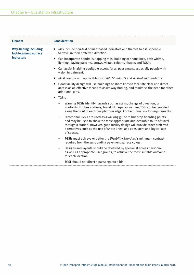
Element Consideration
Way-finding including tactile ground surface indicators
• May include non-text or map-based indicators and themes to assist people to travel in their preferred direction.
• Can incorporate handrails, tapping rails, building or shore lines, path widths, lighting, paving patterns, arrows, vistas, colours, shapes and TGSIs.
• Can assist in aiding equitable access for all passengers, especially people with vision impairment.
• Must comply with applicable Disability Standards and Australian Standards.
• Good facility design will use buildings or shore lines to facilitate clear and direct access as an effective means to assist way-finding, and minimise the need for other additional aids.
• TGSIs
– Warning TGSIs identify hazards such as stairs, change of direction, or gradients. For bus stations, TransLink requires warning TGSIs to be provided along the front of each bus platform edge. Contact TransLink for requirements.
– Directional TGSIs are used as a walking guide to bus stop boarding points and may be used to show the most appropriate and desirable route of travel through a station. However, good facility design will provide other preferred alternatives such as the use of shore lines, and consistent and logical use of spaces.
– TGSIs must achieve or better the Disability Standard’s minimum contrast required from the surrounding pavement surface colour.
– Designs and layouts should be reviewed by specialist access personnel, as well as appropriate user groups, to achieve the most suitable outcome for each location
– TGSI should not direct a passenger to a bin.
48
Chapter 6 – Bus station Infrastructure
Public Transport Infrastructure Manual, Department of Transport and Main Roads, March 2016Public Transport Infrastructure Manual, Department of Transport and Main Roads, March 2016

Element Consideration
Handrails, balustrades and fencing
Handrails
• Handrails are generally used in conjunction with ramps, stairs and walkways.
• Can be used as a form of support and way-finding aid that is compliant with relevant standards.
Balustrades and fencing
• Provide vital separation between people and hazards where access is not permitted.
• Should provide a visually attractive, semi-transparent, and functional system. Fencing can provide a discreet barrier between hazards, such as between two opposite platforms, to promote safe alternative access routes via dedicated crossings or overpasses.
• Fencing should not be installed between the vehicle boarding and alighting space and the connecting platform, as this can pose a potential hazard by restricting passengers’ ability to move safely between vehicles and platforms.
• Fencing should be used at a minimum, and only installed where necessary while still able to promote an open station layout.
• Provide a visually attractive, semi-transparent, and functional system, and be constructed from materials that are robust, contemporary and easily maintained.
• TransLink’s preference is the use of black coloured fencing to promote a discreet yet functional station facility.
• All handrails, balustrades and fencing are to comply with applicable Disability Standards and Australian Standards.
Driver layover amenities/ storeroom
• May be required depending on the function of the station and services operating through the station.
• Where needed, these amenities should be integrated within the station design and located adjacent to bus holding areas. Driver facilities should be separated from passenger areas.
• Layover amenities should include: separate male and female toilets, seating and tables consistent with driver demand, a kitchenette and storeroom (refer to TransLink for typical inclusions and design layout).
• Should appear as a seamless element within the overall composition of the station.
• Consultation with TransLink is recommended to ascertain requirements for operational layover bays and driver facilities. TransLink will consult with the relevant operator to confirm current and forecast requirements.
49
Chapter 6 – Bus station infrastructure
Public Transport Infrastructure Manual, Department of Transport and Main Roads, March 2016

Element Consideration
Shelters • Shelters and all facility structures should project a consistent design language that:
– appears modern, light and spacious
– is of a high quality and standard
– is reflective of the Queensland sub-tropical climate
– is reflective of TransLink’s infrastructure theming and architectural design.
• Structures at platforms must be cantilevered to provide an unobstructed kerb-line (free from posts or other structural supports) and can be single or double-sided cantilever, depending on platform layout.
• Structures must provide complete weather protection during all parts of the day.
• Passenger information displays, signage and way-finding can be attached to the cantilevered structure providing they do not obscure sightlines.
• Shelter structures should include high-quality finishes with modern, durable, and easily maintained materials that are reflective of the overall station environment and climatic conditions (that is, sun, rain, natural light and airflow).
• Examples of these materials include stainless and/or epoxy-painted hot-dipped galvanised steel, glazing, perforated or woven metal and aluminium.
• Liaise with TransLink on the design and specification of existing bus station shelters that are currently installed and in use throughout the network.
Ticketing and public transport information
• Both ticketing and information amenities should be integrated within the design of the station structure and environment, and in locations that do not impede free flowing access paths and walkways.
• Fare machines (such as AVVMs) issue TransLink's integrated transport fares/tickets for use on buses, trains and ferries.
• Stations should have options for customers to purchase paper tickets and to validate electronic go cards.
• Locate fare machines close to entrance points or nominated boarding points taking into consideration the sequence of movement and paid/unpaid areas.
• For bus travel, go card scanning devices are located on-board the bus. Some bus stations may include manned pre-boarding ticketing facilities or staff.
• Passenger transport information can consist of electronic kiosks and static or real-time displays. Information should be located in waiting areas and decision points within the station. Information should include bus timetables, maps, services, special events etc.
• Electronic information displays should face passengers and be positioned at a comfortable viewing angle and height. Designers will need to determine the most suitable quantities and locations for electronic displays.
• The location of ticketing and information amenities must be considered early in the design phase to incorporate appropriate security surveillance and power and data requirements.
50
Chapter 6 – Bus station Infrastructure
Public Transport Infrastructure Manual, Department of Transport and Main Roads, March 2016Public Transport Infrastructure Manual, Department of Transport and Main Roads, March 2016

Element Consideration
Cycle storage • Secure cycle storage and amenities are to be included in the design and layout of all stations.
• Secure cycle storage facilities and cycle rails should be close to station platforms for a safe and easy transfer to passenger transport.
• Cycle storage must be located in a visually-prominent position within or immediately adjacent to the station environment, to allow passive surveillance.
• Materials used for these facilities should be secure, transparent, durable, easily cleaned and resistant to vandalism or abuse.
• The amount of cycle storage provided will be determined by the size and location of the facility and availability of adjoining cycle access paths.
• Consideration should be given to providing appropriate electrical conduits for lighting and in preparation for electronic card access and other future electronic requirements.
For further details on cycle amenities, refer to the PTIM, Supporting access infrastructure.
Public Toilets • Inclusion of public toilets will depend on the station location, level-of-service, staffing arrangements, asset management and passenger comfort and safety.
• Toilet amenities must meet Disability Standards and Australian Standards.
• Toilets should be located in visible and practical, yet discreet, locations and include security requirements.
• Inclusion of toilet amenities must consider construction and installation requirements within station design, such as plumbing and drainage. Generally, a storeroom is included in the toilet facility building for storage of cleaning products and other items needed for station operation and maintenance.
51
Chapter 6 – Bus station infrastructure
Public Transport Infrastructure Manual, Department of Transport and Main Roads, March 2016

Element Consideration
Seating and lean rails • Must be provided in quantities reflective of the expected waiting times and levels of anticipated patronage for the station.
• Seating should be provided at all allocated waiting areas without impeding free flowing access paths and walkways.
• Less seating may be provided at high-frequency service locations due to minimal passenger waiting times and high passenger volumes.
• Seating and lean rails should be provided on platforms where passengers can easily see approaching public transport vehicles, typically where there is complete weather protection and where the environment is safe and well lit. They are typically positioned facing the conveyance and either at the rear of the single-sided platform and shelter or in the centre of a double-sided platform and shelter.
• Seats should include backrests and armrests and be constructed from durable, easily cleaned and maintained materials that allow drainage from liquids.
• Seating may be cantilevered to a wall or shelter structure to allow easier platform maintenance.
• All furniture must offer appropriate contrast in colour with the immediate background.
• Lean rails provide passengers with a convenient waiting option by allowing passengers to perch or lean, rather than be seated, when waiting for brief periods or where waiting space is limited.
• Lean rails generally consist of a horizontal beam supported at either end by vertical posts, or the beam may be attached directly to a wall or station structure. Horizontal beams should be positioned at a height appropriate for the average person.
Bins • Rubbish bins should be provided at all stations.
• Bins are generally located close to waiting or congregation areas, seating, information displays, boarding points, cycle storage areas, and station entries and exits.
• Use of bins at high passenger volume stations, such as regional facilities, may warrant careful consideration due to potential security risks.
• Bins at particular stations should be designed to allow for detection of suspicious objects. They may be constructed from materials with an open gauge to provide transparency (with a transparent clear plastic liner) that is easy to maintain.
• Bin design should aim to be vandal-proof, water-proof and bird-proof. The provision of recycling bins may also be an option and should be considered during the facility detailed design phase.
• Recycle bins may be incorporated adjacent to general waste bins to promote recycling, with appropriate recycling collection arrangements in place.
52
Chapter 6 – Bus station Infrastructure
Public Transport Infrastructure Manual, Department of Transport and Main Roads, March 2016Public Transport Infrastructure Manual, Department of Transport and Main Roads, March 2016

Element Consideration
Drinking fountains • Drinking fountains may be provided at stations.
• They are generally located close to waiting or congregation areas, seating, information displays, cycle storage areas, and station entries and exits.
• Drinking fountains should be constructed from materials that are easy to maintain, and should include stainless steel water catchment and drainage. Furthermore, they must be designed to be accessible for people with disabilities.
Shopping trolley bays/storage
• Where bus stations co-exist with shopping centres or other retail outlets, there may be the requirement to include appropriate, discreet, and easy to maintain shopping trolley bays or storage within or close to the facility.
• The sitting of shopping trolly facilities needs to take into account potential conflict between buses and shopping trolley collection vehicles.
• An agreement from the retail outlet to collect shopping trolleys on a regular basis is also required.
Ancillary services • Key ancillary services can include vending machines, ATMs and other third-party services not directly concerning passenger transport.
• Should be located in visually prominent locations, but not impede a passenger’s ability to access and move through the station.
• Inclusion and location of these services will depend on agreement with third-party stakeholders, station asset management and station designers, and will be determined on a site-specific basis.
• Consideration should be given to the consolidation of ancillary services to reduce visual clutter and to provide a more integrated service for passengers. Generally, these facilities are positioned close to other passenger services such as fare machines, information displays and emergency call points.
• Materials used for ancillary services should be consistent with other passenger facilities to achieve a visually integrated suite of services. Ancillary services should be considered early in the detailed design phase to incorporate relevant security, monitoring, power and data requirements.
Intelligent Transport System (ITS)
• ITS functionality should be considered for all public transport facilities within the context of the broader TransLink network and include security cameras, real-time information, public address systems, incident management systems, and monitoring and communications systems.
• ITS hardware and connection points are typically located in a communications room within the overall facility. These ITS or communications control rooms may adjoin other facilities within the station, such as toilets or storerooms. They should be located in discreet locations within the facility environment, not impede public spaces or free flowing pedestrian access to the station, and be generally signed as ‘staff only’.
• The specific installation (including power, conduits and security) and asset management schedule requirements for the inclusion of the ITS at each facility should be investigated on a site-specific basis prior to detailed design. Specialist ITS personnel should be commissioned when designing the ITS within the station environment.
53
Chapter 6 – Bus station infrastructure
Public Transport Infrastructure Manual, Department of Transport and Main Roads, March 2016

Element Consideration
Public address system • A public address system should be integrated into the design of all station facilities. The aim is to provide a robust, functional and visually discreet system that can provide communicative information and be linked to the security system for warning in the event of an emergency.
• The public address system is to be clearly audible and reverberate throughout the passenger waiting areas. Loudspeakers for the system should be distributed appropriately throughout the station and may be wall or ceiling mounted, depending on acoustic requirements. Speaker units should be mounted at an appropriate distance away from direct reach, or sit flush with station structures, to minimise potential vandalism and damage.
• The possibility of background noise affecting the audibility of the address system should be treated with appropriate acoustic absorption techniques. Loudspeakers for the system should be distributed appropriately throughout the station.
• Hearing augmentation or hearing loops should be included and linked with the public address and emergency systems to assist persons with hearing impairments.
Security • Security infrastructure refers to security cameras and other items used for the creation of safe and well-monitored waiting environments.
• Details on the specifications and management schedules for these systems will be established in collaboration with the facility owner and/or asset manager.
• Appropriate construction and installation requirements must be considered when planning for the inclusion of security infrastructure. The use of signage informing people of the presence of security infrastructure within a facility can further enhance personal safety, and highlight the perceived risk of detection to potential offenders.
• Security help points are typically located in the centre of platforms or other key waiting areas. Ultimately, the location of all these elements should be the subject of station specific design, as each site is likely to have a range of differing sightlines and movement patterns.
• Counter-terrorism design considerations should be explored where possible on a site-specific basis, depending on station location, level-of-service and potential security risk. Where applicable, station design should strive towards universal standards for security and counter-terrorism measures. Liaise with the Emergency Management and Transport Security division in the Department for advice on including security and counter-terrorism measures at the earliest phase in the station planning.
54
Chapter 6 – Bus station Infrastructure
Public Transport Infrastructure Manual, Department of Transport and Main Roads, March 2016Public Transport Infrastructure Manual, Department of Transport and Main Roads, March 2016

Element Consideration
Lighting • Ambient lighting is to be provided for a safe, comfortable and functional station.
• Feature lighting may highlight architectural features.
• For day-time use, consider translucent materials to allow natural lighting.
• For night-time, bright white artificial lighting should ensure a safe and visually attractive environment.
• High quality light fixtures and fittings should be robust, tamper-proof, discreet and complement the station environment.
• Use of common fixtures will improve maintenance and lower ongoing costs.
• Provide lighting on pedestrian areas, roadways and station information.
• Lighting at bus stations must comply with the applicable requirements of lighting subcategory P6 within AS/NZ 1158.3.1 – Lighting for roads and public spaces.
• For additional disability compliance lighting requirements refer to the Disability Standards for Accessible Public Transport 2002 (DSAPT).
Graffiti deterrents and treatments
• All infrastructure components—furniture, lighting equipment, timetable and information devices, walls, floors, ceilings, balustrades, glass panels, screens, elevators, escalators and other components—coming into contact with passengers must be resistant to acts of vandalism and graffiti. This may involve components being applied with anti-graffiti coatings or constructed from non-porous graffiti-resistant materials.
• The design and arrangement of platforms and structures should maximise natural surveillance in order to minimise the incidence of graffiti and anti-social behaviour.
• In some instances, vegetation may be planted adjacent to structures or walls to prevent access by vandals.
• The use of appropriate colours or artwork that complements the station architecture and theming can also deter graffiti.
Animal and pest problems • Within the station there must be minimal horizontal ledges, overhangs, or concealed spaces where birds and animals are tempted to perch, nest and pollute the station facility.
• If cavities and horizontal surfaces are unavoidable, then appropriate measures are to be used to prevent animals and pests congregating and/or nesting. This can include designing ledges of structures to be angled (approximately 45 degrees or greater) to make it uncomfortable for birds to perch.
55
Chapter 6 – Bus station infrastructure
Public Transport Infrastructure Manual, Department of Transport and Main Roads, March 2016

Element Consideration
Landscape Treatment • Landscape treatment is to be incorporated (where appropriate) to complement the station architecture, enhance the identification of a particular location, and integrate the facility with the surrounding environment. It is preferred that plantings used for landscaping are:
– drought resistant
– consistent with the surrounding natural environment (for example, local flora)
– unlikely to intrude upon the integrity of the station environment
– unlikely to interfere with above and below ground services and utilities
– not toxic, highly allergenic or noxious weeds
– not known to produce thorns, barbs, stings or noxious secretions
– not inhibiting sightlines, passive surveillance or allowing for potential offenders to hide.
Commercial opportunities • Commercial opportunities are typically developed and operated by external companies under an agreed arrangement.
• It may be appropriate to incorporate:
– vending machines
– commercial advertising
– retail outlets, such as cafes, coffee carts, newsagents and convenience stores.
• Endorsement of commercial facilities is required prior to detailed design to make allowance for space, power, data and conduits for installation.
Other enhancements • Artwork can enhance a station identity and cultural significance of a place, and should be investigated where appropriate.
• Public art should not conflict with station architecture, colour schemes, branding and access requirements.
• Wireless internet access options and connections may be investigated and incorporated.
• The facility owner and/or asset manager, along with relevant stakeholders, should endorse all enhancements prior to the detailed design stage of the facility.
56
Chapter 6 – Bus station Infrastructure
Public Transport Infrastructure Manual, Department of Transport and Main Roads, March 2016Public Transport Infrastructure Manual, Department of Transport and Main Roads, March 2016

6.10 Technical detailsAppendix 6-A provides design examples of bus station infrastructure. The specifications of components shown represent good practice, and consistent and modular design, as identified by TransLink.
The specifications shown should be interpreted as a guide, with site-specific attention given to individual station locations and constraints.
Contact TransLink for design direction and more detailed specifications, prior to design commencement, to determine specific location requirements.
57
Chapter 6 – Bus station infrastructure
Public Transport Infrastructure Manual, Department of Transport and Main Roads, March 2016

Appendix 6-AAppendix 6-A 58
Typical single and double bus station platform arrangement plans
59
Typical single and double bus station shelter elevations
60
Typical bus driver facility 61
Typical secure bike storage facility 62
58
Chapter 6 – Bus station Infrastructure
Public Transport Infrastructure Manual, Department of Transport and Main Roads, March 2016Public Transport Infrastructure Manual, Department of Transport and Main Roads, March 2016