
BUS MODULE MODBUS RTU - Advanced Energy€¦ · The bus module Modbus RTU can connect up to 8 power...
37
BUS MODULE MODBUS RTU FOR THYRO-S, THYRO-A AND THYRO-AX July 2014 DE/EN - V3
-
Upload
hoangnguyet -
Category
Documents
-
view
237 -
download
3
Transcript of BUS MODULE MODBUS RTU - Advanced Energy€¦ · The bus module Modbus RTU can connect up to 8 power...

1
BUS MODULE MODBUS RTU fOR ThyRO-S, ThyRO-A AnD ThyRO-AX
July 2014 DE/En - V3

2
COnTACT InfORMATIOn
TEChnICAL qUERIESDo you have any technical queries regarding the subjects dealt with inthese operating instructions?If so, please get in touch with our team for power controllers:Phone +49 (0) 2902 763-520
COMMERCIAL qUERIESDo you have any commercial queries on power controllers?If so, please get in touch with our team for power controllers.Phone +49 (0) 2902 763-558
SERVICEAdvanced Energy Industries GmbhBranch Office Warstein-BeleckeEmil-Siepmann-Straße 32D-59581 WarsteinPhone +49 (0) 2902 763-0http://www.advanced-energy.com
COPyRIGhTno part of these operating instructions may be transmitted, reproduced and/or copied by any electronic or mechanical means without the express prior written permission of Advanced Energy.© Copyright Advanced Energy Industries Gmbh 2014.All rights reserved.
fURThER InfORMATIOn On COPyRIGhTThyro-™, Thyro-S™, Thyro-A™, Thyro-AX™ are registered trademarks of Advanced Energy Industries Gmbh. All other company and product names are (registered) trademarks of the respective owners.

3
1. Introduction 5
1.1 General 5
1.2 Specific characteristics 5
1.3 Type designation 5
1.4 Warranty 5
2. Safety 7
2.1 Identification in the operating instructions 7
2.2 General danger information 8
2.3 Operator requirements 9
2.4 Personnel requirements 9
2.5 Intended purpose 9
2.6 Use of the device 10
2.6.1 Operation 10
2.6.2 Prior to installation/start-up 10
2.6.3 Maintenance, service, faults 10
2.6.4 Transport 10
3. functions 11
3.1 Setpoint processing Thyro-S 11
3.2 Setpoint processing Thyro-A/Thyro-AX 12
3.3 Operating display 13
3.4 Additional functions for Thyro-S, Thyro-A and Thyro-AX 13
4. Operation 14
4.1 Selecting the bus address 14
4.2 Setting the communication parameters 14
4.3 Modbus-/J-bus log 15
4.3.1 Read holding registers (0x03) 16
4.3.2 Preset single register (0x06) 17
4.3.3 Preset multiple registers (0x10) 18
4.3.4 Report slave ID (0x11) 18
4.3.5 Exception response 19
4.4 Register allocation 19
4.4.1 Busmodule parameters 20
4.4.2 Controller parameters 21
COnTEnTS

4
fig. 1 Relay drive 13
fig. 2 Block connecting diagram bus module 27
fig. 3 Connecting plans Thyro-A/Thyro-AX 30
fig. 4 Connecting plans Thyro-S 31
Tab. 1 Interpretation of master setpoints with Thyro-S 11
Tab. 2 Status of diagnosis LED 13
Tab. 3 Register allocation of bus module for J-Bus and Modbus RTU 19
Tab. 4 Bus module parameters 20
Tab. 5 Device types 20
Tab. 6 Bus module master 21
Tab. 7 Controller actual values 21
Tab. 8 Controller parameters 22-23
Tab. 9 Status and error flags 25-26
LIST Of ILLUSTRATIOnS AnD TABLES
4.5 Status and error communication 25
5. External connections 27
5.1 Power supply 27
5.2 Operating elements and terminal strips 28
6. Interfaces 29
6.1 System interface 29
6.2 Modbus interface 29
7. Connecting plans Thyro-A/Thyro-AX 30
8. Connecting plans Thyro-S 31
9. Special remarks 32
9.1 Installation 32
9.2 Commissioning 32
9.3 Service 32
10. Technical Data 33
11. Dimensional drawings 33
12. Accessories and options 34
13. Approvals and conformity 34
5
1. InTRODUCTIOn
The following operating instructions merely serve as a supplement andapply only in connection with the operating instructions of the Advanced Energy power controllers Thyro-S and Thyro-A of types h1 and h RL1, as well as Thyro-A h RLP1 as well as Thyro-AX of types h RL2 and h RLP2. Particular attention must be paid to the safety instructions included in them.
1.1 GEnERALThe bus module Modbus RTU can connect up to 8 power controllers oftype Thyro-A...1, Thyro-AX...2 or power switches of type Thyro-S…1 to a Mod-bus master in any random order.Several bus modules can be employed at one device. Each bus moduleoccupies one address on the Modbus.The power supply of the bus module is provided by an external 24 V d.c. power source (150 mA), which is fed into X11.1 (+) and X11.2 (ground) (reverse battery protected). The 24 V d.c. supply must be ungrounded when operating under SELV. Several modules can be operated at one power supply.for EMC reasons, the earth connection to X11.3 must be as short as possible. The Modbus connector with a 9-terminal standard allocation must be con-nected to the socket X20.
1.2 SPECIfIC ChARACTERISTICS• The bus module is a slave component• Function control via LED• 8 free digital outputs X1.5 to X8.5• processing of actual values as float number in physical units• C-rail assembly• When the bus module is linked to Thyro-AX, please be aware that data trans-
fer is the same as for Thyro-A whereas special features or other additional parameters are excluded from this.
1.3 TyPE DESIGnATIOnBus module Modbus RTU Order no. 2000 000 842

6
1.4 WARRAnTyIn the event of any claims in connection with the Modbus RTU, please contact us immediately quoting:- Type designation- Works number/Serial number- Reason for the complaint- Environmental conditions of the device- Operating mode- Period of use
Goods and services are subject to the general conditions of supply forproducts of the electrical industry, and our general sales conditions.Claims in connection with supplied goods must be submitted within one week of receipt, along with the delivery note. Advanced Energy will rescind all obligations such as warranty agreements, service contracts, etc. entered into by Advanced Energy or its representatives without prior notice if main-tenance and repair work is carried out using anything other than original Ad-vanced Energy spare parts or spare parts purchased fromAdvanced Energy.

7
2. SAfETy
2.1 IDEnTIfICATIOn In ThE OPERATInG InSTRUCTIOnSIn these operating instructions, there are warnings before dangerousactions. These warnings are divided into the following danger categories:
DAnGERDangers that can lead to serious injuries or fatal injuries.
WARnInGDangers that can lead to serious injuries or considerable damage to property.
CAUTIOnDangers that can lead to injuries and damage to property.
CAUTIOnDangers that can lead to minor damage to property.
The warnings can also be supplemented with a special danger symbol(e.g. „Electric current“ or „hot parts“), e.g.
risk of electric current or
risk of burns.

8
In addition to the warnings, there is also a general note for useful information.
nOTEContent of note
2.2 GEnERAL DAnGER InfORMATIOn
DAnGER failure to observe the safety regulations in the operating instructions for the power controllers used risk of injury or damage to the device or plant.> Observe all safety regulations in the safety chapter of the operating instruc-
tions for the power controllers used.
DAnGERElectric currentRisk of injury from live parts/risk of damage to the bus module.> never operate the device without the cover.> Only carry out adjustments or wiring when the device is deenergised.
CAUTIOnRisk of damage to the bus moduleThe current at terminals X1.5 to X8.5 may not exceed 120 mA.> Check the connection data of the upstream relay.
nOTECommunication faultsTo avoid communication faults, observe the following points:> Use shielded cables.> Ensure grounding on the bus module (X1.7 to X8.7). Do not also ground on
the power controller.
9
2.3 OPERATOR REqUIREMEnTSThe operator must ensure the following:- That the safety regulations of the operating instructions are observed.- That the accident prevention regulations valid in the respective coun-try of
use and the general safety regulations are observed.- That all safety devices (covers, warning signs etc.) are present, in perfect
condition and are used correctly.- That national and regional safety regulations are observed.- That the personnel has access to the operating instructions and safety
regulations at all times.- That operating conditions and restrictions resulting from the technical data
are observed.- That, should abnormal voltages, noises, increased temperatures, vibra-
tion or similar occur, the device is immediately put out of operation and the maintenance personnel is informed.
2.4 PERSOnnEL REqUIREMEnTSOnly qualified electro-technical personnel who are familiar with thepertinent safety and installation regulations may perform the following:- Transport- Installation- Connection- Start-up- Maintenance- Testing- Operation.
These operating instructions must be read carefully by all persons working with or on the equipment prior to installation and initial start-up.
2.5 InTEnDED PURPOSEThe device may only be used for the pupose for which it was intended,as persons may otherwise be exposed to dangers (e.g. electric shock,burns) and plants also (e.g. overload). The user must therefore observethe following points:- It is not permitted to make any unauthorised modifications to the
unit or to use any spare parts or replacement parts not approved by Advan-ced Energy, or to use the unit for any other purpose.
10
- The warranty obligations of the manufacturer are only applicable if these operating instructions are observed and complied with.
- The device is a component that cannot function alone.- Project planning must account for the proper use of the device.
2.6 USE Of ThE DEVICE
2.6.1 OPERATIOn- Only switch on the mains voltage at the machine when there is no danger to
persons, system or load.- Protect the device against dust and damp.- Ensure that the ventilation openings are not blocked.
2.6.2 PRIOR TO InSTALLATIOn/START-UP- If stored in a cold environment: ensure that the device is absolutely dry. (Allow the device a period of at least two hours to acclimatise before start-up.)- Ensure sufficient ventilation of the cubicle if mounted in a cubicle.- Observe minimum spacing.- Ensure that the device cannot be heated up by heat sources below it (see
chapter 10, Technical data).- Ground the device in accordance with local regulations.- Connect the device in accordance with the connection diagram.
2.6.3 MAInTEnAnCE, SERVICE, fAULTSIn order to avoid injuries and damage, the user must observe the following:- Before all work: > Disconnect the device from all external voltage sources. > Secure the device against accidentally being switched back on. > Use suitable measuring instruments and check that there is no voltage
present. > Ground and short-circuit the device. > Provide protection by covers or barriers for any neighbouring live parts.- The device may only be serviced and repaired by trained electrotechnical
personnel.
2.6.4 TRAnSPORT- Only transport the device in the original packaging.- Protect the device against damage, caused by jolts, knocks and contamina-
tion, for instance.

11
3. fUnCTIOnS
3.1 SETPOInT PROCESSInG Thyro-SThe setpoints via the bus (setpoints master) are interpreted as an operating mode with Thyro-S as shown in table 1.
SETPOInT RETURn VALUE
(setpoint master) (total setpoint)
to 409 = Off 0
to 1091 = 1/5 819
to 1706 = 1/3 1365
to 3071 = 1/2 2047
to 4096 = On 4096
TAB. 1 InTERPRETATIOn Of ThE MASTER SETPOInTS WITh Thyro-S
The setpoint processing continues to depend on how the bus module isconnected to the power controller. for Thyro-S different variations canbe realised as required. The connection of terminal X22.4 of Thyro-Scontrols the procedures (Chapt. 8, fig. 4).
• no connection to X22.4 The bus module is fully functional, only the analog signal of control terminal X22.1, however, is used as a setpoint (On / Off).
• X22.4 has ground potential Only the master setpoints are used by the bus module (graded as in table 1). The controller’s terminal X22.4 can be directly connected to earth if an alter-native operation is excluded.
• X22.4 is switched • Thyro-S’s terminal X22.4 is connected to one of the terminals X1.1 to X8.1
of the bus module (fig. 4). With malfunctions on the bus line an automatic switchover takes place to the corresponding signal of the setpoint input of Thyro-S.
• Thyro-S’s connection X22.4 is connected to one of the terminals X1.5 to X8.5 of the bus module (fig. 4). The controllers can then individually be switched (selectively) via bus to „hand”. With malfunctions on the bus line the last setpoint is automatically retai-ned.

12
• Digital outputs with free drives If a terminal X1.5 to X8.5 of the bus module is not allocated, a relay with 24 V d.c. coil can be connected for free use (fig. 1). The free circuit is integrated.
The driver current is maximum 120mA per output. Ventilation cabinets, auxiliary heating, circuit breakers or control lamps for
example, can be activated with this via the Modbus.
3.2 SETPOInT PROCESSInG Thyro-A/Thyro-AXThe setpoint processing depends on how the bus module is connected to the power controller. for Thyro-A/Thyro-AX different variations can be realised depending on the requirements. The connection of terminal X22.1 of Thyro-A/Thyro-AX controls the procedures (Chapt. 7, fig. 3).• no connection to X22.1
The bus module is fully functional, however, only the analog signal of con-trol terminal X2.4 is used as the setpoint.
• X22.1 has ground potential Only the master setpoint is accepted by the bus module as a setpoint. The controller’s terminal X22.1 can be directly connected to earth if an alternati-ve operation is excluded.
• X22.1 is switched • The terminal X22.1 of Thyro-A/Thyro-AX is connected to one of the termi-
nals X1.1 to X8.1 of the bus module (fig. 3). With malfunctions on the bus line all controllers are automatically swit-ched over to the respective analog signal of the setpoint input of Thyro-A/Thyro-AX.
• The circuit X22.1 of Thyro-A/Thyro-AX is connected to one of the terminals X1.5 to X8.5 of the bus module (fig.3). Then each controller can be switched individually (selectively) via bus to „hand”. With malfunctions on the bus line the last setpoint is automatically retai-ned.
• Digital outputs with free drives If a terminal X1.5 to X8.5 of the bus module is not allocated, a relay with 24 V d.c. coil can be connected for free use (fig. 1). The free circuit is integrated. The driver current is maximum 120 mA per output. Ventilation cabinets, auxiliary heating, circuit breakers or control lamps, for example, can be switched via the Modbus.

13
fIG. 1 RELAy DRIVE
3.3 OPERATIOn DISPLAy
STATUS LED MODBUS InDICATIOn
On – Card error
BLInKS with 1 hz Off no bus signal present
BLInKS with 1 hz ACTIVE Card error
Off OffPower supply absent(also green LED off)
Off ACTIVE Everything OK
TAB. 2 STATUS DIAGnOSIS LED
3.4 ADDITIOnAL fUnCTIOnS fOR Thyro-S, Thyro-A AnD Thyro-AXBy using a bus module, additional functions for the power controllersThyro-S, Thyro-A and Thyro-AX can be employed.All the accessible parameters of both type ranges can be found incolumns S/A (abbreviation for Thyro-S and Thyro-A; these modifications also apply for Thyro-AX) under R/W in table 8.The most important parameters are described in more detail in theaccording power controller operating instructions. here r = read, i.e. can only be read, r/w = read and write possible.
14
4. OPERATIOn
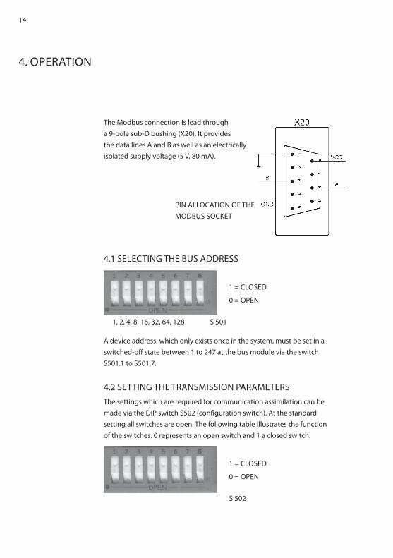
The Modbus connection is lead througha 9-pole sub-D bushing (X20). It providesthe data lines A and B as well as an electricallyisolated supply voltage (5 V, 80 mA).
4.1 SELECTInG ThE BUS ADDRESS
A device address, which only exists once in the system, must be set in aswitched-off state between 1 to 247 at the bus module via the switchS501.1 to S501.7.
4.2 SETTInG ThE TRAnSMISSIOn PARAMETERSThe settings which are required for communication assimilation can bemade via the DIP switch S502 (configuration switch). At the standardsetting all switches are open. The following table illustrates the functionof the switches. 0 represents an open switch and 1 a closed switch.
1 = CLOSED
0 = OPEn
1, 2, 4, 8, 16, 32, 64, 128 S 501
1 = CLOSED
0 = OPEn
S 502
PIn ALLOCATIOn Of ThE MODBUS SOCKET

15
S 502
SWITCh fUnCTIOn
1 2 3 4 5 6 7 8
0 0 0 4800 Baud
1 0 0 9600 Baud
0 1 0 19200 Baud
1 1 0 38400 Baud
0 0 1 57600 Baud
1 0 1 115200 Baud
0 1 1 230400 Baud
1 Parity
1 Even nOdd
1 2 Stopp-Bit
1 Long Break
x free
Baud rate: Works setting = 4800 Baud.The baud rate can be set with the first three switches. The transmissionrates of 4800 to 230 400 baud are sustained.
Parity: Works setting = no parityThis switch activates transmission with parity bit.
Even nOdd: Works setting = OddWith activated parity bit it is possible to switch between Even and Oddparity.
2 Stopp-Bit: Works setting = 1 Stopp BitThis switch allows an additional Stopp Bit to be sent.
Long Break: Works setting = no extensionThis switch allows the delay time between master inquiry and slave reply to be increased by 3.5 bytes.
4.3 MODBUS-/J BUS LOGThe transmission mode RTU (Remote Terminal Unit) is used for communica-tion.
General telegram set up:

16
START ADDRESS fUnCTIOn DATA ByTES
CRC EnD
Pause >3,5 bytes
1 byte 1 byte x bytes 2 bytes Pause >3,5 bytes
The following functions are sustained:1. Read holding Register
Reads one or more registers from the slave.2. Preset Single Register
Changes a register in the slave.3. Preset Multiple Regs
Changes several registers in the slave.4. Report Slave ID
Reads the slave ID of the slave.
The individual registers as well as the calculations of the correspondingregister addresses are described in chapter 4.4. The J-bus registeraddress is always used (i.e. also with Modbus) within the telegrams.
4.3.1 READ hOLDInG REGISTERS (0X03)With this telegram the master can read out one or more registers (function code 0x03). The registers must lie in series.Example: Registers 72 + 128 (load voltage chapter 4.4, Controller 1) are to be read out from the bus module with the address 100. (72 + 128 = 200, no overflow into high byte).
Inquiry:
ADDRESS fUnCTIOn REGISTER nUMBER CRC
100 3 0, 200 0, 2 76, 00
Response:
ADDRESS fUnCTIOn nO. ByTES
DATA CRC
100 3 4 250, 184, 70, 23 13, 166
Error: Should the address of the register to be read out lie outside the address location, the reply Exception Response „ILLEGAL DATAADDRESS” is transmitted (see chapter 4.3.5).

17
Response:
ADDRESS fUnCTIOn ERROR CODE CRC
100 131 2 208, 238
If more than 120 registers are requested simultaneously the ExceptionResponse „ILLEGAL DATA VALUE” is transmitted (see Chapt. 4.3.5).
Response:
ADDRESS fUnCTIOn ERROR CODE CRC
100 131 3 17, 46
4.3.2 PRESET SInGLE REGISTER (0X06)With this telegram the master can change a register (function code 0x06).
Example: Registers 6 + 256 (operating mode Thyro-A/Thyro-AX, Controller 2) are to be changed to 2 (VAR) in the bus module with the address 100 (1 overflow into high byte).
Inquiry:
ADDRESS fUnCTIOn REGISTER DATA CRC
100 6 1, 6 0, 2 224, 3
Response:
ADDRESS fUnCTIOn REGISTER DATA CRC
100 6 1, 6 0, 2 224, 3
Error:Should the register’s address lie outside the address location or isan attempt made to write on an address that cannot be changed, theException Response responds by transmitting „ILLEGAL DATAADDRESS” (see Chapt. 4.3.5). This is also the case if the controller inquestion is not connected!
Response:
ADDRESS fUnCTIOn ERROR CODE CRC
100 134 2 211, 190
18
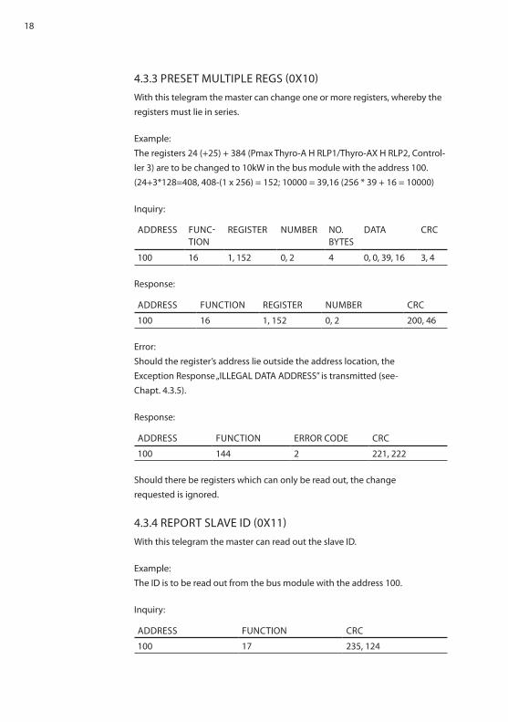
4.3.3 PRESET MULTIPLE REGS (0X10)With this telegram the master can change one or more registers, whereby the registers must lie in series.
Example: The registers 24 (+25) + 384 (Pmax Thyro-A h RLP1/Thyro-AX h RLP2, Control-ler 3) are to be changed to 10kW in the bus module with the address 100.(24+3*128=408, 408-(1 x 256) = 152; 10000 = 39,16 (256 * 39 + 16 = 10000)
Inquiry:
ADDRESS fUnC-TIOn
REGISTER nUMBER nO. ByTES
DATA CRC
100 16 1, 152 0, 2 4 0, 0, 39, 16 3, 4
Response:
ADDRESS fUnCTIOn REGISTER nUMBER CRC
100 16 1, 152 0, 2 200, 46
Error:Should the register’s address lie outside the address location, theException Response „ILLEGAL DATA ADDRESS” is transmitted (see-Chapt. 4.3.5).
Response:
ADDRESS fUnCTIOn ERROR CODE CRC
100 144 2 221, 222
Should there be registers which can only be read out, the changerequested is ignored.
4.3.4 REPORT SLAVE ID (0X11)With this telegram the master can read out the slave ID.
Example:The ID is to be read out from the bus module with the address 100.
Inquiry:
ADDRESS fUnCTIOn CRC
100 17 235, 124

19
Response:
ADDRESS fUnC-TIOn
nO. ByTES SLAVE ID RUn STA-TUS
CRC
100 17 2 4 255 18, 116
4.3.5 EXCEPTIOn RESPOnSEWith an incorrect inquiry an Exception Response is transmitted and theinquiry is rejected.
ILLEGAL fUnCTIOn:The function code received in the inquiry is not sustained by the slave.
ILLEGAL DATA ADDRESS:The register address does not exist. It must be smaller than 1152. Withthe inquiries „Read holding Registers” and „Preset Multiple Regs” theaddress comprises the register’s start address and the number of registers. So that the following applies Register + number <1152; 128+8x128.
ILLEGAL DATA VALUE:The data in the inquiry are not permitted. for example the number ofregisters to be read is too high (max. 120).
4.4 REGISTER ALLOCATIOnThe registers are split up into the following areas:
PARAMETERS REGISTER ADDRESSES
J-BUS MODBUS
Bus module 0 - 127 40001 - 40128
Controller X1 128 - 255 40129 - 40256
Controller X2 256 - 383 40257 - 40384
Controller X3 384 - 511 40385 - 40512
Controller X4 512 - 639 40513 - 40640
Controller X5 640 - 767 40641 - 40768
Controller X6 768 - 895 40769 - 40896
Controller X7 896 - 1023 40897 - 41024
Controller X8 1024 - 1151 41025 - 41152
TAB. 3 REGISTER ALLOCATIOn Of ThE BUS MODULE fOR J-BUS AnD MOD-BUS RTU
20
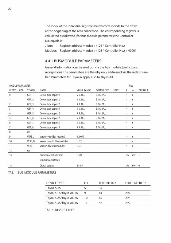
The index of the individual registers below corresponds to the offsetat the beginning of the area concerned. The corresponding register iscalculated as followed (for bus module parameters the Controller no. equals 0):J-bus: Register address = index + (128 * Controller no.)Modbus: Register address = Index + (128 * Controller no.) + 40001
4.4.1 BUSMODULE PARAMETERSGeneral information can be read out via the bus module (participantrecognition). The parameters are thereby only addressed via the index num-ber. Parameters for Thyro-A apply also to Thyro-AX.
MODUL-PARAMETER R/W
InDEX ADR. SyMBOL nAME VALUE RAnGE COMBO-OPT UnIT S A DEfAULT
0 GER_1 Device type at port 1 5, 9, 10, .. S, 1A, 2A,.. r r
1 GER_2 Device type at port 2 5, 9, 10, .. S, 1A, 2A,.. r r
2 GER_3 Device type at port 3 5, 9, 10, .. S, 1A, 2A,.. r r
3 GER_4 Device type at port 4 5, 9, 10, .. S, 1A, 2A,.. r r
4 GER_5 Device type at port 5 5, 9, 10, .. S, 1A, 2A,.. r r
5 GER_6 Device type at port 6 5, 9, 10, .. S, 1A, 2A,.. r r
6 GER_7 Device type at port 7 5, 9, 10, .. S, 1A, 2A,.. r r
7 GER_8 Device type at port 8 5, 9, 10, .. S, 1A, 2A,.. r r
8 res.
9 VERS_J Version year (Bus module) 0...9999 r r
10 VERS_M Version month (Bus module) 1...12 r r
11 VERS_T Version day (Bus module) 1...31 r r
12 res.
13 number of act. val. from
which mean is taken
1...20 r/w r/w 1
14 Digital outputs Bit 0-7 r/w r/w 0
TAB. 4 BUS MODULE PARAMETERS
DEVICE TyPE h1 h RL1/h RL2 h RLP1/h RLP2
Thyro-S 1S 5 37 –
Thyro-A 1A/Thyro-AX 1A 9 41 297
Thyro-A 2A/Thyro-AX 2A 10 42 298
Thyro-A 3A/Thyro-AX 3A 11 43 299
TAB. 5 DEVICE TyPES

21
4.4.2 COnTROLLER PARAMETERSR/W
InDEX SETPOInT TyPE nO. REG. UnIT S A RESTRICT.
64 Setpoint Master integer 1 4096=100% r/w r/w
TAB. 6 SETPOInT MASTER
R/W
InDEX ACTUAL VALUES TyPE nO. REG. UnIT S A RESTRICT.
70 Power L1 float 2 W r only h RLP1/h RLP2
72 Load voltage L1 float 2 V r r
74 Current L1 float 2 A r r only Thyro-A h RL../Thyro-AX h RL..
76 Supply voltage L1 integer 1 V r r
80 Power L2 float 2 W r only Thyro-A 3A h RLP1/Thyro-AX 3A h RLP2
82 Load voltage L2 float 2 V r r only Thyro-A 3A/Thyro-AX 3A
84 Current L2 float 2 A r r only Thyro-A 3A h RL../Thyro-AX 3A h RL..
86 Supply voltage L2 integer 1 V r r only Thyro-A 3A/Thyro-AX 3A
90 Power L3 float 2 W r only Thyro-A 2A h RLP1/Thyro-AX 2A h RLP2
92 Load voltage L3 float 2 V r only Thyro-A 2A/Thyro-AX 2A
94 Current L3 float 2 A r only Thyro-A h RL../Thyro-AX h RL..
96 Mains voltage L3 integer 1 V r only Thyro-A 2A/Thyro-AX 2A
100 Total power float 2 W r only h RLP1/h RLP2
102 Total setpoint integer 1 4096 = 100% r r
103 Setpoint input terminal integer 1 4096 = 100% r r
104 Connection angle alpha integer 1 °el. r
105 Act. value connection time integer 1 period r r
106 Period duration integer 1 ms r r
107 Temperature integer 1 °C r r
115 Error integer 1 s. Tab. 9a r r
116 Status integer 1 s. Tab. 9b r r
TAB. 7 COnTROLLER ACTUAL VALUES
nOTEfor Thyro-S a setpoint conversion is made (see chapter 3.1)
The following tables show the maximum available actual values of a control-ler. If parameters are not used, they are 0.
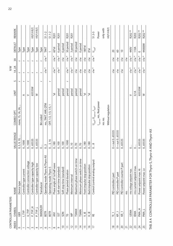
22CO
nTR
OLL
ER P
ARAM
ETER
SR/
W
InD
EXSy
MBO
Ln
AME
VALU
E RA
nG
ECO
MBO
-OPT
.U
nIT
S1A
, 2A
3AD
EfAU
LTRE
MAR
K
0G
ERD
evic
e ty
pe0,
5, 9
, 10,
…no
ne, 1
S, 1
A, 2
A, ...
r
rr
Type
1I_
TyP
Cont
rolle
r typ
e cu
rrent
0...1
000
A
rr
rTy
pe
2U
_TyP
Cont
rolle
r con
nect
ion
volta
ge0.
..100
0
Vr
rr
Type
3P_
TyP_
hCo
ntro
ller t
ype
capa
city
hig
h0.
..655
35
6553
5W
rr
Type
h RLP
1/h RL
P2
4P_
TyP_
LCo
ntro
ller t
ype
capa
city
low
0...6
5535
W
r
rTy
peh R
LP1/h
RLP2
5W
AnD
LER
Tran
sduc
er0…
Bit c
oded
r
rr
Type
6BE
TRO
pera
ting
mod
e Th
yro-
A/Th
yro-
AX0.
..3re
s., TA
KT, V
AR, q
TM
r/
w *
r/w
*TA
KTS1
.1-2
7BE
TRO
pera
ting
mod
e Th
yro-
S0…
3, 1
6O
ff, 1
/2, 1
/3, 1
/5, 1
r
1S1
.1-2
8An
1Ph
ase
angl
e of
1st
hal
f wav
e0.
..180
°el
r/
w *
r/w
*60
°el
R201
9SS
TSo
ft st
art t
ime
(sta
ndar
d)0.
..100
perio
d
r/w
*r/
w *
6 pe
riod
R201
10SD
nSo
ft st
op ti
me
(sta
ndar
d)0.
..100
perio
dr/
w6
perio
d
11T0
Phas
e pe
riod
dura
tion
0...1
000
perio
dr
r/w
*r/
w *
50 p
erio
dR2
01
12M
PM
inim
um in
terv
al0.
..10
perio
d
r/w
*r/
w *
3 pe
riod
R201
13TS
MAX
Max
imum
pha
se sw
itch-
on ti
me
0...T
0pe
riod
r/
wr/
w50
per
iod
14TS
MIn
Min
imum
pha
se sw
itch-
on ti
me
0...T
0pe
riod
r/
wr/
w0
perio
d
15V_
IEfr
ont i
mpu
lse st
op p
ositi
on0.
..180
°e
l
r/w
r/w
180°
el
16h
_IE
Back
impu
lse st
op p
ositi
on0.
..180
°e
l
r/w
r/w
0°el
17RE
Cont
rol (
cont
rol a
nalo
g ou
tput
)0…
8U lo
ad2,
U load
rms, I lo
ad2,
I load
rms, r
es., R
eal p
ower
res.
res.
With
out r
egul
atio
n
r/w
*r/
w *
Ulo
ad2
S1.3
-5
Pow
er
only
with
h RLP
1/h RL
P2
18TI
_1PI
D c
ontro
ller I
par
t0
= ou
t 0...6
5535
r/
wr/
w20
19KP
_1PI
D c
ontro
ller P
par
t0
= ou
t 0...6
5535
r/
wr/
w60
20KR
_1PI
D c
ontro
ller c
ount
er P
par
t0.
..655
35
r/w
r/w
10
21re
s.r/
w
22U
EMA
rms v
olta
ge se
tpoi
nt m
ax.
0…V
r/
w *
r/w
*44
0VR2
02 **
23IE
MA
rms c
urre
nt se
tpoi
nt m
ax.
0…0,
1A
r/w
*r/
w *
110A
R203
24PM
A_h
Pow
er se
tpoi
nt m
ax. h
i0.
..655
35
6553
5W
r/w
*r/
w *
0R2
02 **
25PM
A_L
Pow
er se
tpoi
nt m
ax. L
o0.
..655
35
W
r/w
*r/
w *
4400
0WR2
02 **
TAB.
8 A
CO
nTR
OLL
ER P
ARA
MET
ER f
OR
Thyr
o-S,
Thy
ro-A
An
D T
hyro
-AX

23
COn
TRO
LLER
PAR
AMET
ERS
R/W
InD
EXSy
MBO
Ln
AME
VALU
E RA
nG
ECO
MBO
-OPT
.U
nIT
S1A
, 2A
3AD
EfAU
LTRE
MAR
K26
SW_A
CTIV
Setp
oint
act
ivat
ion
0…3
"Bit0
=1 (S
etpo
int X
2.4
activ
e), B
it1=1
(Set
poin
t Mas
ter a
ctiv
e)
rr
r0
27
res.
28
res.
29
res.
30O
fAn
alog
out
put o
ffset
0...4
095
20/40
95 m
A
r/w
*r/
w *
0mA
S1.9
31fA
Scal
e en
d va
lue
of a
nalo
g ou
tput
0...4
095
1
/ 819
r/
w *
r/w
*1
R204
32SP
G_M
InPo
wer
mon
itor c
ircui
t min
.0.
..100
0
Vr/
wr/
wr/
wTy
pe
33SP
G_M
AXPo
wer
mon
itor c
ircui
t max
.0.
..100
0
Vr/
wr/
wr/
wTy
pe
34U
n_S
Und
ercu
rrent
mon
itor
0...1
Off,
On
r
r/w
*r/
w *
Aus
R205
35re
s.r/
w
36LA
STBR
UCh _
MIn_
ABS
Load
faul
t min
. val
ue0…
4095
10
0/40
95 %
rr/
w *
r/w
*0%
R205
37re
s.r/
w
38Sy
nC_
ADR
Sync
hron
ous p
hase
add
ress
0...6
5535
perio
d / 2
r/
wr/
w10
039
IMAB
Impu
lse c
ut-o
ff w
ith fa
ult
0...6
5535
Bit c
oded
r/w
r/w
r/w
0
40ST
A_RE
Cont
r. sta
rt co
ntr. a
nalo
g se
tpoi
nt va
lue
0...4
095
20/40
95 m
A
r/w
*r/
w *
0mA
S1.6
41ST
E_RE
Cont
r. end
cont
r. ana
log
setp
oint
valu
e0.
..409
520
/4095
mA
r/
wr/
w20
mA
42
res.
r/
w
43M
OSI
_fA
Peak
load
val
ue li
mit
0...4
095
r/w
r/w
Type
44DA
C1_C
TRL
Anal
og o
utpu
t con
figur
atio
n0…
10
r/w
r/w
r/w
6
45re
s.r/
wr/
wr/
w
46VE
RS_T
Vers
ion
day
1...3
1
rr
r
47VE
RS_M
Vers
ion
mon
th1.
..12
r
rr
48VE
RS_J
Vers
ion
year
0...9
999
r
rr
49re
s.
50
Cont
rolle
r loc
k0.
..1O
ff, O
n
r/w
r/w
Off
51RE
LAIS_
CTRL
Rela
y co
nfigu
ratio
n 1
0...6
5535
Bit c
oded
r/
wr/
w44
7
52St
ore
0...1
Off,
Sav
e
r/w
r/w
r/w
Off
53M
ITTE
LM
ean
valu
e an
alog
ue o
utpu
t0.
..655
35
r/
wr/
w10
0
TAB.
8 B
CO
nTR
OLL
ER P
ARA
MET
ER f
OR
Thyr
o-S,
Thy
ro-A
An
D T
hyro
-AX

24
REMARKIf a potentiometer or contact of DIP switch S1 is entered in the “note” column of the table, this hardware setting is used when the mains returns (for excep-tions, see * or **)* In the “Thyro-Tool” mode (switch S1.3-5 on “On”) the parameters marked
with * are not given by the switches and Potis, instead, the stored values are used.
** The allocation of the parameters marked with ** to the Poti depends on the chosen controller mode.
25
DESCRIPTIOn: Thyro-A/Thyro-AX Thyro-S
Thyro-S, Thyro-A and Thyro-AX LEDs RELAy* LEDs RELAy*
frequency measurement outside
of 47 hz to 63 hz
Bit0 Pulse Inhibit LED
flashes slowly
dropped out Test LED flashes slowly dropped out
SynC error, no zero crossing within
the gate
Bit1 Pulse Inhibit LED
flashes slowly
dropped out Test LED flashes slowly dropped out
Temperature monitoring triggered Bit2 Load fault LED
flashes slowly
dropped out Load Fault flashes slowly dropped out
Load error Bit3 Load fault LED on dropped out Load fault on dropped out
flash values invalid Bit4 Pulse Inhibit LED and Load
Fault LED flash fast simulta-
neously
dropped out Test LED a. Load fault LED
flash fast simultaneously
dropped out
Mains Undervoltage
(< AD_P_SPG_MIn)
Bit5 Pulse Inhibit LED,
Load fault LED a.
Test-LED on
dropped out Load fault LED and
Test LED on
dropped out
Mains Overvoltage
(> AD_P_SPG_MAX)
Bit6 none energised none energised
Master/Slave error (only with 2A) Bit8 none energised only with Thyro-A/Thyro-AX ---
Undervoltage Limit Bit9 none energised only with Thyro-A/Thyro-AX ---
Overvoltage Limit Bit10 none energised only with Thyro-A/Thyro-AX ---
Undercurrent Limit Bit11 none energised only with Thyro-A/Thyro-AX ---
Overcurrent Limit Bit12 none energised only with Thyro-A/Thyro-AX ---
Low Power Limit Bit13 none energised only with Thyro-A/Thyro-AX ---
high Power Limit Bit14 none energised only with Thyro-A/Thyro-AX ---
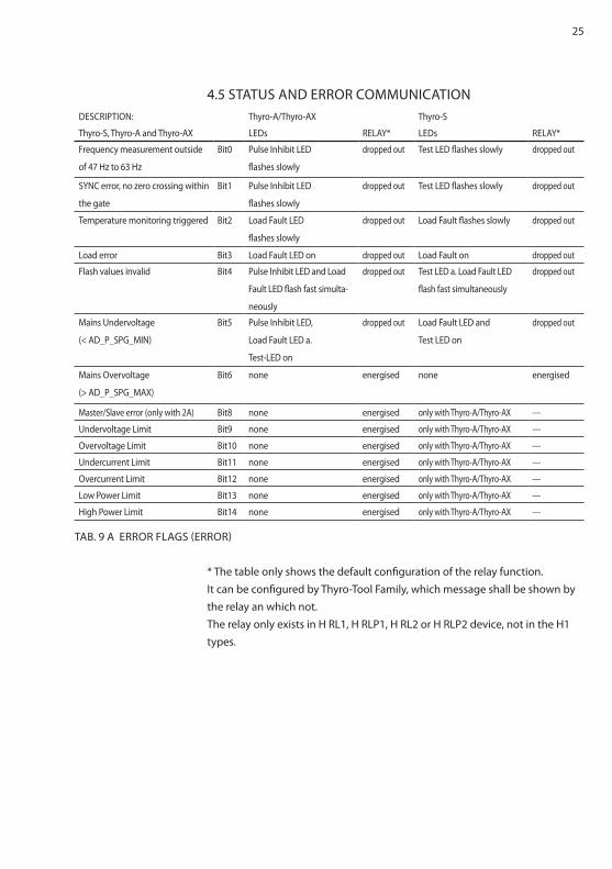
TAB. 9 A ERROR fLAGS (ERROR)
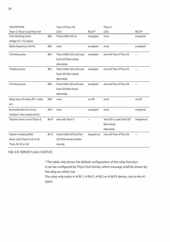
4.5 STATUS AnD ERROR COMMUnICATIOn
* The table only shows the default configuration of the relay function. It can be configured by Thyro-Tool family, which message shall be shown by the relay an which not. The relay only exists in h RL1, h RLP1, h RL2 or h RLP2 device, not in the h1 types.
26
* The table only shows the default configuration of the relay function. It can be configured by Thyro-Tool family, which message shall be shown by the relay an which not. The relay only exists in h RL1, h RLP1, h RL2 or h RLP2 device, not in the h1 types.
DESCRIPTIOn: Thyro-A/Thyro-AX Thyro-S
Thyro-S, Thyro-A and Thyro-AX LEDs RELAy* LEDs RELAy*
Pulse blocking active
(bridge X2.1-X2.2open)
Bit0 Pulse Inhibit LED on energised none energised
Mains frequency is 60 hz Bit2 none energised none energised
U limiting active Bit4 Pulse Inhibit LED and Load
Fault LED flash slowly
alternately
energised only with Thyro-A/Thyro-AX ---
I limiting active Bit5 Pulse Inhibit LED and Load
Fault LED flash slowly
alternately
energised only with Thyro-A/Thyro-AX ---
P limiting active Bit6 Pulse Inhibit LED and Load
Fault LED flash slowly
alternately
energised only with Thyro-A/Thyro-AX ---
Relay status (0=relay off/ 1=relay
on)
Bit8 none on/off none on/off
Busmodul aktiv (0=no bus
module/1=bus modul active)
Bit11 none energised none energised
Thyristor short-circuit (Thyro-S) Bit14 only with Thyro-S --- Test-LED a. Load fault LED
flash slowly
alternately
dropped out
failure in rotating field/
phase (only Thyro-A 2A or 3A/
Thyro-AX 2A or 3A)
Bit15 Pulse Inhibit LED and Test
LED flash slowly simulta-
neously
dropped out only with Thyro-A/Thyro-AX ---
TAB. 9 B ERROR fLAGS (STATUS)
27
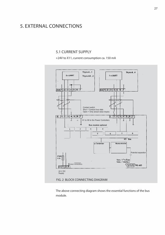
5. EXTERnAL COnnECTIOnS
5.1 CURREnT SUPPLy+24V to X11, current consumption ca. 150 mA
The above connecting diagram shows the essential functions of the busmodule.
fIG. 2 BLOCK COnnECTInG DIAGRAM
2
Contact switchShut = Conduct bus dataOpen = Only actual value inquiry
2
X1 to X8 to the Power Controllers
Bus module optional
Screen connections
24 V DCSupply
Potential separation
Thyro-A ..1
Thyro-AX ..2
28
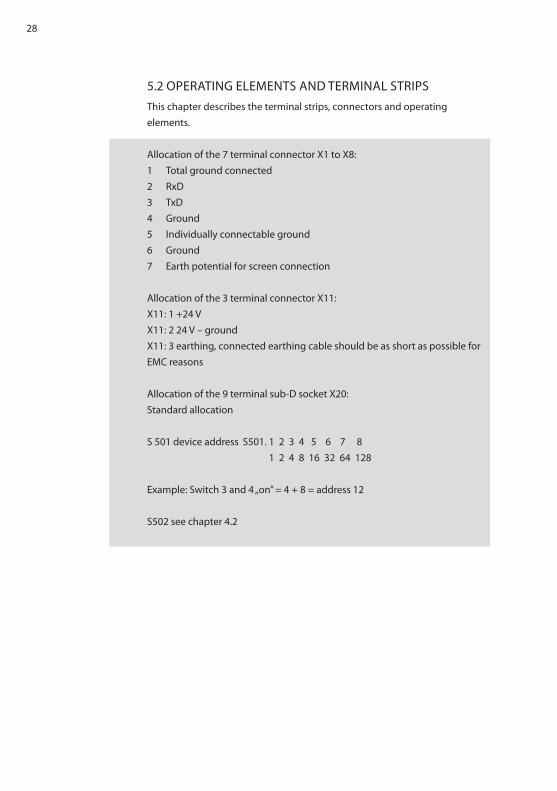
5.2 OPERATInG ELEMEnTS AnD TERMInAL STRIPSThis chapter describes the terminal strips, connectors and operatingelements.
Allocation of the 7 terminal connector X1 to X8:1 Total ground connected2 RxD3 TxD4 Ground5 Individually connectable ground6 Ground7 Earth potential for screen connection
Allocation of the 3 terminal connector X11:X11: 1 +24 VX11: 2 24 V – groundX11: 3 earthing, connected earthing cable should be as short as possible for EMC reasons
Allocation of the 9 terminal sub-D socket X20:Standard allocation
S 501 device address S501. 1 2 3 4 5 6 7 8 1 2 4 8 16 32 64 128
Example: Switch 3 and 4 „on” = 4 + 8 = address 12
S502 see chapter 4.2
29
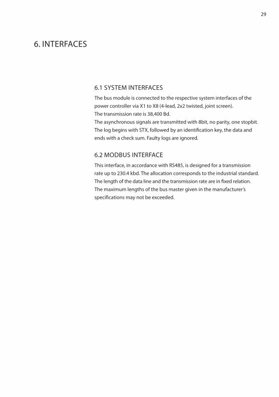
6. InTERfACES
6.1 SySTEM InTERfACESThe bus module is connected to the respective system interfaces of thepower controller via X1 to X8 (4-lead, 2x2 twisted, joint screen).The transmission rate is 38,400 Bd.The asynchronous signals are transmitted with 8bit, no parity, one stopbit. The log begins with STX, followed by an identification key, the data andends with a check sum. faulty logs are ignored.
6.2 MODBUS InTERfACEThis interface, in accordance with RS485, is designed for a transmissionrate up to 230.4 kbd. The allocation corresponds to the industrial standard.The length of the data line and the transmission rate are in fixed relation.The maximum lengths of the bus master given in the manufacturer’sspecifications may not be exceeded.

30
7. COnnECTInG PLAnS Thyro-A/Thyro-AX
fIG. 3 COnnECTInG PLAnS Thyro-A/Thyro-AX

31
fIG. 4 COnnECTInG PLAnS Thyro-S
8. COnnECTInG PLAnS Thyro-S

32
9. SPECIAL REMARKS
9.1 InSTALLATIOnThe bus module can be arranged as desired.On delivery the device is set at:bus address 000, baudrate 4 800 bd, no parity, Odd, 1 stopbit, no extension set.
9.2 COMMISSIOnInG• Set address switch according to bus plan application• Set configuration switch• Carry out cabling• Feed 24V d.c. - green LED must light up,
- bus module is ready for operation, - red LED stops blinking as soon as the Modbus starts operating.
• Should errors occur, the bus master’s log must be eval.
9.3 SERVICEThe delivered devices have been produced under quality standard ISO9001. Should nevertheless faults or problems arise, please contact our Advanced Energy team for assistance (see chapter COnTACT InfORMATIOn).

33
10. TEChnICAL DATA
Voltage supply 24 VDC (+/-20 %) 150 mA
Possible bus addresses 1 to 247, only one address necessary per bus module
Connection options Up to 8 Advanced Energy power controllers of the Thyro-S, Thyro-A and Thyro-AX series of types ...h1, ...h RL1, ...h RLP1, ...h RL2 and ...h RLP2
function check Via LEDs
Mounting On DIn rail
Ambient temperature Max. 65 °C
11. DIMEnSIOnAL DRAWInGS
Phoenix EMG 150 casing150x75x55 mm without upper part of plug,recommended space required 150x150 mm

34
12. ACCESSORIES AnD OPTIOnS
13. APPROVALS AnD COnfORMITy
Cord set, screened cables are available with the bus module.One loom of cables consists of 4 equally long connecting cables for theconnection of 4 power controllers.
Order no. 2000 000 848 Bus module connecting cable for 4 controllers, 2.5 m longOrder no. 2000 000 849 Bus module connecting cable for 4 controllers, 1.5 m long
- Data transmission in acc. with ISO 11898- quality standard in acc. with DIn En ISO 9001- CE conformity- Low voltage directive 73/23 EEC- EMC directive 89/336 EEC; 92/31 EEC- Marking directive 93/68 EEC
DIRECTIVESThe CE mark on the device confirms compliance with the EC directives72/23 EEC for low voltage and 89/339 EEC for electromagnetic compatibility if the instructions on installation and start-up described in the operating instructions are followed.

35
In Detail
DEVICE APPLICATIOn COnDITIOnS
Integrated device (VDE0160) DIn En 50 178General requirements DIn En 60146-1-1:12.97Design, vertical installationOperating conditions DIn En 60 146-1-1; ch. 2.5Area of application, industrial CISPR 6Temperature behaviour DIn En 60 146-1-1; ch. 2.2Storage temperature (D) -25 °C – +55 °CTransport temperature (E) -25 °C – +70 °COperating temperature (better B) -10 °C – +55 °Chumidity class B DIn En 50 178 Tab. 7 (En 60 721)Degree of contamination 2 DIn En 50 178 Tab. 2Air pressure 900 mbar * 1000 m above m. sea levelIndex of protection IP00 DIn En 69 529Protection class III DIn En 50178 chap. 3Mechanical jolt DIn En 50 178 chap. 6.2.1Tests in acc. with DIn En 60 146-1-1 4.EMC emitted interference En 61000-6-4Radio interference suppression control unit Class A DIn En 55011:3.91 CISPR 11EMC resistance En 61000-6-2ESD 8 kV (A) En 61000-4-2:3.96Burst control lines 1 kV (A) En 61000-4-4Conductor-bound En 61000-4-6

36
World headquarters
1625 Sharp Point Drive
fort Collins, CO 80525 USA
970.221.4670 Main
970.221.5583 fax
www.advanced-energy.com
Specifications are subject to change without notice.
© 2014 Advanced Energy Industries, Inc. All rights reserved. Advanced Energy® and Thyro-S™, Thyro-A™, Thyro-AX™ are trademarks of Advanced Energy Industries, Inc.

37