Burner control units BCU 480 - morterahauck.com · The burner control unit BCU 480 is de-signed for...
25
6.1.2.8 Edition 06.07 Product brochure · GB www.kromschroeder.com For pilot and main burners of unlimited capacity in intermittent or continuous operation pursuant to EN 746-2 Automatic burner control unit, ignition transformer, indicators and operating controls in a space-saving metal housing which replaces the local burner control cabinet Flame control by UV, ionisation or a further option of using the furnace chamber temperature Display of the program status, unit parameters and flame signal; manual mode for burner adjustment and for diagnostic purposes Visualisation and adaptation to the specific application via the PC programming and diagnostic software BCSoft to simplify logistics management Spacious connection chamber with plug-in terminal blocks and plug-in cable glands for quick installation and servicing Air valve control relieves the furnace control Optional PROFIBUS-DP interface EC type-tested and certified • • • • • • • • • Burner control units BCU 480 www.morterahauck.com [email protected]
Transcript of Burner control units BCU 480 - morterahauck.com · The burner control unit BCU 480 is de-signed for...

6.1.2.8 Edition 06.07Product brochure · GB
www.kromschroeder.com
For pilot and main burners of unlimited capacity in intermittent or continuous operation pursuant to EN 746-2
Automatic burner control unit, ignition transformer, indicators and operating controls in a space-saving metal housing which replaces the local burner control cabinet
Flame control by UV, ionisation or a further option of using the furnace chamber temperature
Display of the program status, unit parameters and flame signal; manual mode for burner adjustment and for diagnostic purposes
Visualisation and adaptation to the specific application via the PC programming and diagnostic software BCSoft to simplify logistics management
Spacious connection chamber with plug-in terminal blocks and plug-in cable glands for quick installation and servicing
Air valve control relieves the furnace control
Optional PROFIBUS-DP interface
EC type-tested and certified
•
•
•
•
•
•
•
•
•
Burner control units BCU 480
www.morterahauck.com [email protected]
BCU 480 · Edition 06.072 · Kromschröder
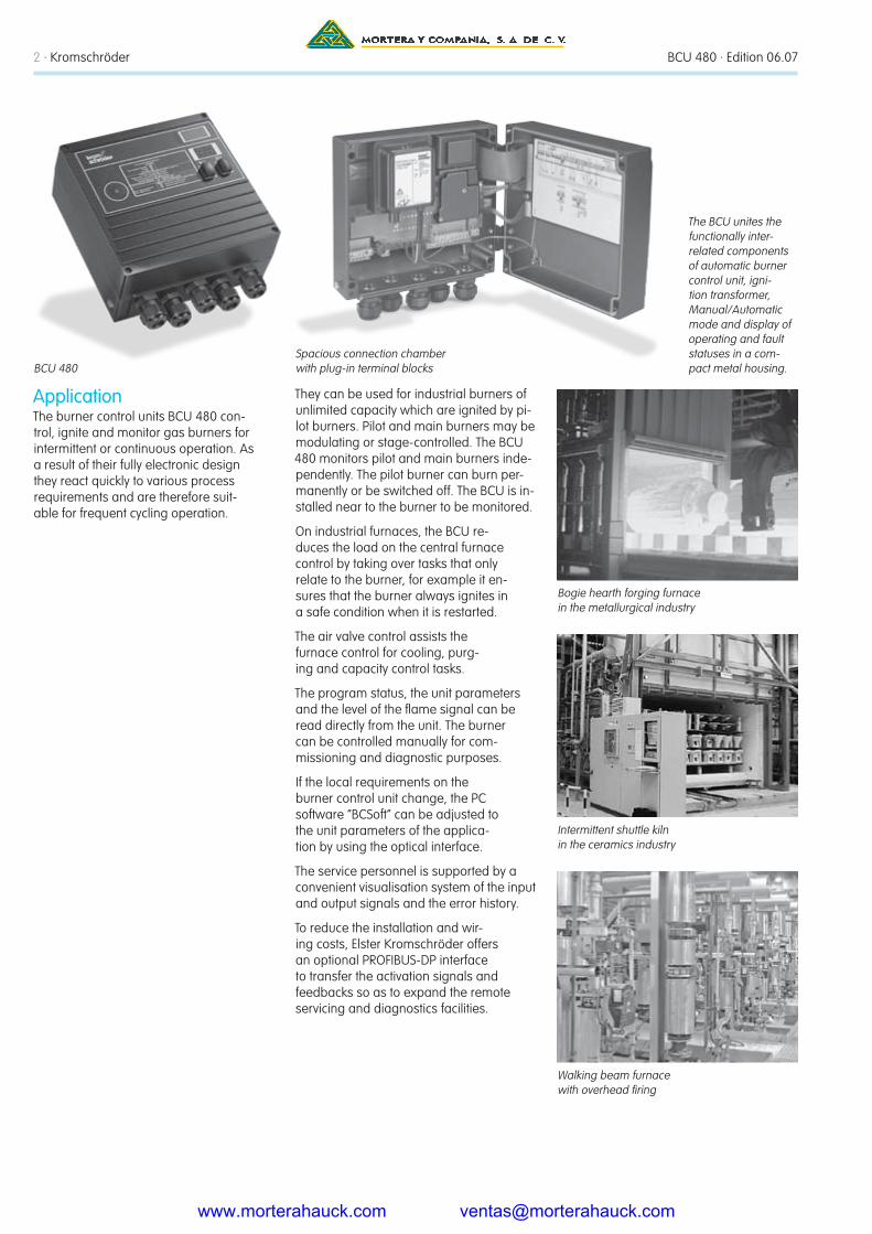
The BCU unites the functionally inter-related components of automatic burner control unit, igni-tion transformer, Manual/Automatic mode and display of operating and fault statuses in a com-pact metal housing.
ApplicationThe burner control units BCU 480 con-trol, ignite and monitor gas burners for intermittent or continuous operation. As a result of their fully electronic design they react quickly to various process requirements and are therefore suit-able for frequent cycling operation.
They can be used for industrial burners of unlimited capacity which are ignited by pi-lot burners. Pilot and main burners may be modulating or stage-controlled. The BCU 480 monitors pilot and main burners inde-pendently. The pilot burner can burn per-manently or be switched off. The BCU is in-stalled near to the burner to be monitored.
On industrial furnaces, the BCU re-duces the load on the central furnace control by taking over tasks that only relate to the burner, for example it en-sures that the burner always ignites in a safe condition when it is restarted.
The air valve control assists the furnace control for cooling, purg-ing and capacity control tasks.
The program status, the unit parameters and the level of the flame signal can be read directly from the unit. The burner can be controlled manually for com-missioning and diagnostic purposes.
If the local requirements on the burner control unit change, the PC software “BCSoft” can be adjusted to the unit parameters of the applica-tion by using the optical interface.
The service personnel is supported by a convenient visualisation system of the input and output signals and the error history.
To reduce the installation and wir-ing costs, Elster Kromschröder offers an optional PROFIBUS-DP interface to transfer the activation signals and feedbacks so as to expand the remote servicing and diagnostics facilities.
Bogie hearth forging furnace in the metallurgical industry
Intermittent shuttle kiln in the ceramics industry
Walking beam furnace with overhead firing
Spacious connection chamber with plug-in terminal blocksBCU 480
www.morterahauck.com [email protected]
BCU 480 · Edition 06.07 Kromschröder · 3
BCU 480
14 12
23
26
SPSPLCAPI
DI
L1, N, PE
P22 4 21
1819
1617
2829
242
1
t
1
2
A
P
53
DI
6
02–0402–04 06–08 06–08
ϑ2ϑ1
ϑ1
ϑ2
µC
VR..L
VAG
UV
VBY
21
t
1
2
BCU 480
14 12
23
26
SPSPLCAPI
DI
L1, N, PE
P22 4 21
1819
1617
2829
242
1
A
P
53
DI
6
0402–04 06–08 06–08 04
µC
ϑ1 ϑ2
ϑ1
ϑ2VR..R
VAG
VBY
21
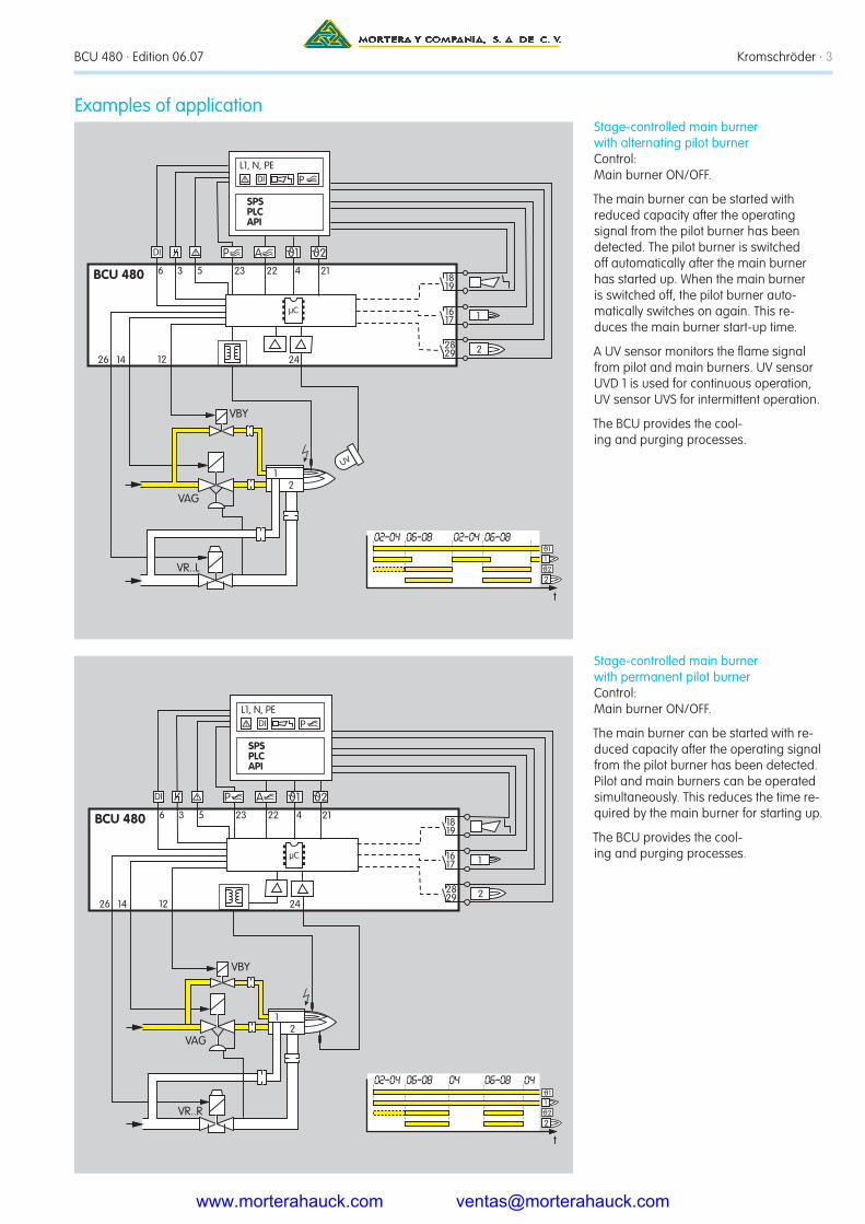
Stage-controlled main burner with alternating pilot burnerControl: Main burner ON/OFF.
The main burner can be started with reduced capacity after the operating signal from the pilot burner has been detected. The pilot burner is switched off automatically after the main burner has started up. When the main burner is switched off, the pilot burner auto-matically switches on again. This re-duces the main burner start-up time.
A UV sensor monitors the flame signal from pilot and main burners. UV sensor UVD 1 is used for continuous operation, UV sensor UVS for intermittent operation.
The BCU provides the cool-ing and purging processes.
Examples of application
Stage-controlled main burner with permanent pilot burnerControl: Main burner ON/OFF.
The main burner can be started with re-duced capacity after the operating signal from the pilot burner has been detected. Pilot and main burners can be operated simultaneously. This reduces the time re-quired by the main burner for starting up.
The BCU provides the cool-ing and purging processes.
www.morterahauck.com [email protected]

BCU 480 · Edition 06.07 Kromschröder · 4
BCU 480
12
23
SPSPLCAPI
DI
L1, N, PE
P22 4 21
1819
1617
2829
242
1
A
P
53
DI
6
VBY
µC
ϑ1 ϑ2
t
1
2
0402–04 06–08 06–08 04ϑ1
ϑ2
21
BV
IC 40
4
7 M
142650 51
VAG
VAS
BCU 480
14 12
SPSPLCAPI
DI
L1, N, PE
4 211819
1617
282924
2
1
P
53
DI
6
mA
µC
ϑ1 ϑ2
VAG
VBY
BV+IC
M
21
Two-stage-controlled main burner with permanent pilot burnerControl: Main burner ON/OFF with ignition via bypass.
The main burner can be started at low-fire rate after the operating signal from the pilot burner has been detected. When the operating state is reached, the BCU issues the Enable signal for the maxi-mum burner capacity. Pilot and main burners can be operated simultane-ously. This reduces the time required by the main burner for starting up.
The BCU provides the cool-ing and purging processes.
Modulating-controlled burnerControl: Main burner continuous
The butterfly valve for air is moved to igni-tion position in order to start the main burner. The main burner can be started at low-fire rate after the operating signal from the pilot burner has been detected. The control system controls the burner capacity via the butterfly valve for air after the operating state has been signalled. Pilot and main burners can be operated simultaneously. This reduces the time re-quired by the main burner for starting up.
www.morterahauck.com [email protected]

BCU 480 · Edition 06.075 · Kromschröder
PROFIBUS-DP
BCU 480..B
BUS1–6
BCU 480..B
BUS
BCU 480..B
BUS1–6 1–6
SPSPLCAPI
DI
L1, N, PEP
BUS
STW
L1
DI
BCU 480..D
DI
>750 °C
69 24
BCU 480..D
69 24
µCµC
BCU 480..B1 for PROFIBUS-DPThe bus system transfers the control signals for starting, resetting and for controlling the air valve from the con-trol system to the BCU 480..B1. In the opposite direction it sends operating status, the level of the flame signals and the current program status.
Control signals that are relevant for safety, such as the safety interlocks, purge (optional) and digital input, are transferred independently of the bus communication by separate cables.
BCU 480..D: High temperature equipmentIndirect flame control using the tempera-ture. During the start-up process, as long as the wall temperature is below auto ignition temperature the flame must be controlled by conventional methods. When the working temperature has exceeded 750°C, the safety temperature monitor (STW) takes over the indirect flame control.
Technical dataMains voltage: 230 V AC, -15/+10%, 50/60 Hz, 115 V AC, -15/+10%, 50/60 Hz, for grounded and ungrounded mains.
Voltage to inputs and valves = mains voltage.
Output current: max. 2 A per out-put, but total current for valves and ignition transformer max. 2.5 A.
Operation and fault signalling contacts: Dry contact, max. 2 A, 264 V, not fused internally.
Flame control: sensor voltage approx. 230 V AC, sensor current > 1 μA.
Length of sensor cable: max. 50 m (164 ft).
Fuse in unit: F1: 3.15 A, slow-acting, H pursuant to IEC 127-2/5, F3: 3.15 A, slow-acting, H pursuant to IEC 127-2/5.
Ambient temperature: -20 to +60°C (-4 to +140°F), climate: no condensation permitted.
Enclosure: IP 54 pursuant to IEC 529.
Weight: Approx. 5 kg (11 lb) depending on version.
BCU..B1External fuse: 12 A per zone.
Certification
The burner control unit BCU 480 is de-signed for applications pursuant to the Machinery Directive (98/37/EC).
EC type-tested and certifiedpursuant to
– Gas Appliances Directive (90/396/EC) in conjunction with EN 298
– Low Voltage Directive (73/23/EEC) in conjunction with EN 60730
– Electromagnetic Compatibil-ity Directive (89/336/EEC)
AGACertified under No. 6478
FMBCU..T is FM approved.
Standard: Factory Mutual Research Standard 7610: June 1997
Suitable for applications pur-suant to NFPA 86
Profibus User OrganisationBCU..B1
PUO = PROFIBUS User Organisation, Certificate No. Z 00692 pursu-ant to EN 50170-1, -3
www.morterahauck.com [email protected]
BCU 480 · Edition 06.076 · Kromschröder
Kromschröder, a product brand of the Elster Group
Detailed information on this productwww.docuthek.com
Contactwww.kromschroeder.com ➔ Sales
Elster Kromschröder GmbH Postfach 2809 · 49018 Osnabrück Strotheweg 1 · 49504 Lotte (Büren) Germany
T +49 541 1214-0 F +49 541 1214-370 [email protected]
www.elster.com www.kromschroeder.com
We reserve the right to make technical modifications in the interests of progress.
Copyright © 2007 Elster Group All rights reserved.
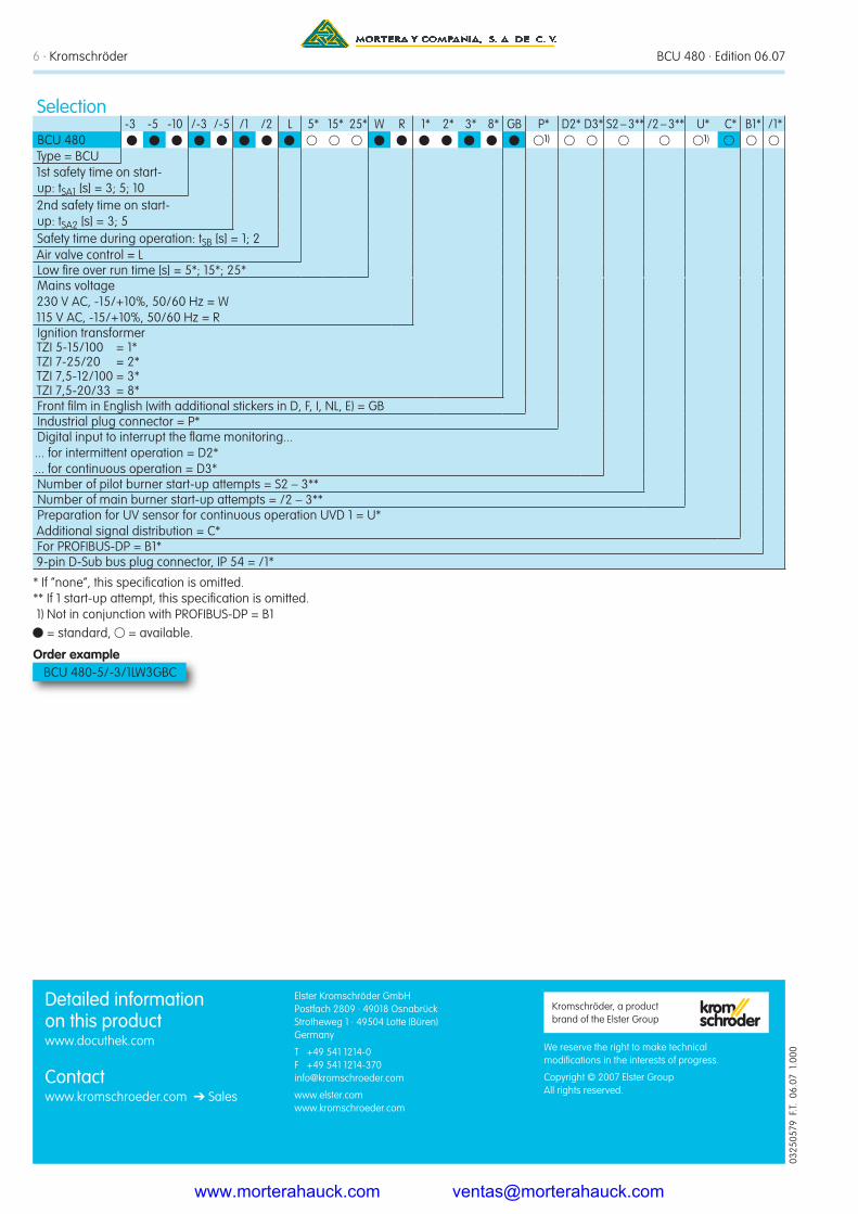
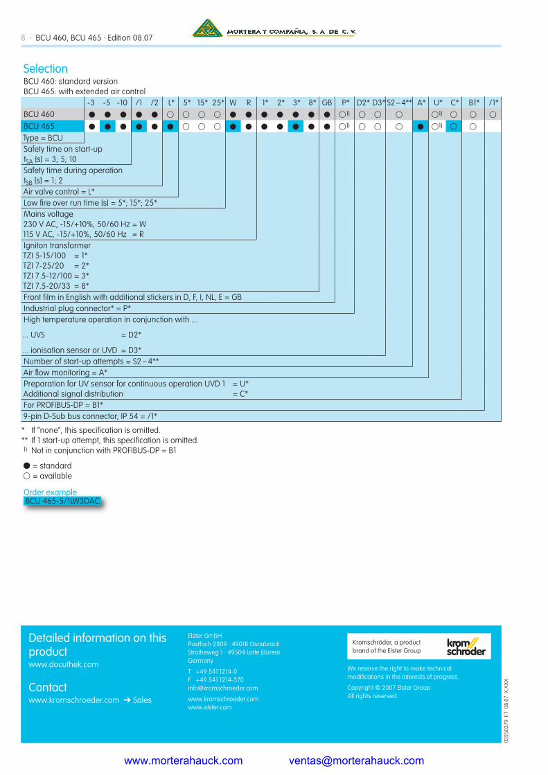
Selection-3 -5 -10 /-3 /-5 /1 /2 L 5* 15* 25* W R 1* 2* 3* 8* GB P* D2* D3* S2 – 3** /2 – 3** U* C* B1* /1*
BCU 480 1) 1) Type = BCU1st safety time on start-up: tSA1 [s] = 3; 5; 102nd safety time on start-up: tSA2 [s] = 3; 5Safety time during operation: tSB [s] = 1; 2Air valve control = LLow fire over run time [s] = 5*; 15*; 25*Mains voltage 230 V AC, -15/+10%, 50/60 Hz = W 115 V AC, -15/+10%, 50/60 Hz = RIgnition transformer TZI 5-15/100 = 1* TZI 7-25/20 = 2* TZI 7,5-12/100 = 3* TZI 7,5-20/33 = 8*Front film in English (with additional stickers in D, F, I, NL, E) = GBIndustrial plug connector = P*Digital input to interrupt the flame monitoring... ... for intermittent operation = D2* ... for continuous operation = D3*Number of pilot burner start-up attempts = S2 – 3**Number of main burner start-up attempts = /2 – 3**Preparation for UV sensor for continuous operation UVD 1 = U* Additional signal distribution = C*For PROFIBUS-DP = B1*9-pin D-Sub bus plug connector, IP 54 = /1*
* If “none”, this specification is omitted. ** If 1 start-up attempt, this specification is omitted. 1) Not in conjunction with PROFIBUS-DP = B1
= standard, = available.
Order example BCU 480-5/-3/1LW3GBC
0325
0579
F.T.
06.
07 1
.000
www.morterahauck.com [email protected]

6.1.2.6 Edition 08.07Product brochure · GB
www.kromschroeder.com
Burner control units BCU 460, BCU 465
Automatic burner control unit, ignition transformer, indicators and operating controls in a space-saving metal housing which replaces the local burner control cabinet
For directly ignited burners of unlimited capacity in intermittent or continuous operation pursuant to EN 746-2
Flame control by UV, ionisation or a further option of using the furnace chamber temperature
Display of the program status, device parameters and flame signal; manual mode for burner adjustment and for diagnostic purposes
Visualisation and adaptation to the specific application via the PC programming and diagnostic software BCSoft to simplify logistics management
Spacious connection chamber with plug-in terminal blocks and plug-in cable glands for quick installation and servicing
Air valve control in BCU..L relieves the furnace control
Optional PROFIBUS-DP interface
EC type-tested and certified
•
•
•
•
•
•
•
•
•
www.morterahauck.com [email protected]
2 · BCU 460, BCU 465 · Edition 08.07
The BCU unites the functionally inter-related components of automatic burner control unit, igni-tion transformer, Manual/Automatic mode and display of operating and fault statuses in a com-pact metal housing.
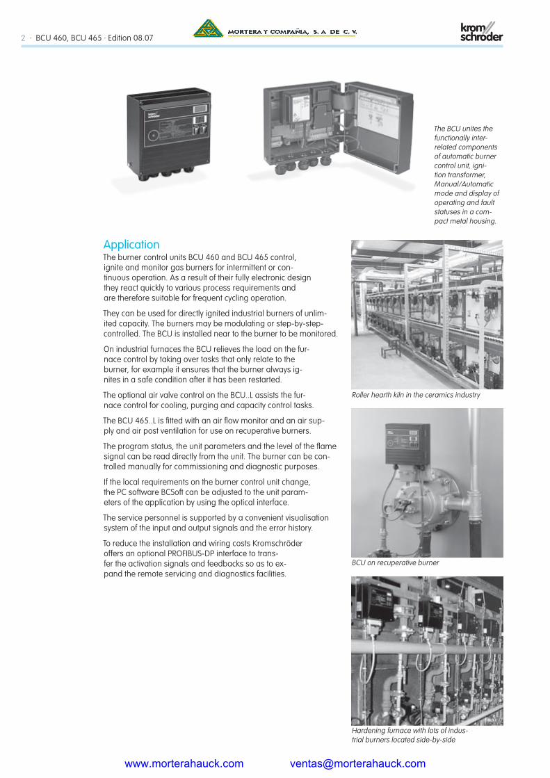
ApplicationThe burner control units BCU 460 and BCU 465 control, ignite and monitor gas burners for intermittent or con-tinuous operation. As a result of their fully electronic design they react quickly to various process requirements and are therefore suitable for frequent cycling operation.
They can be used for directly ignited industrial burners of unlim-ited capacity. The burners may be modulating or step-by-step-controlled. The BCU is installed near to the burner to be monitored.
On industrial furnaces the BCU relieves the load on the fur-nace control by taking over tasks that only relate to the burner, for example it ensures that the burner always ig-nites in a safe condition after it has been restarted.
The optional air valve control on the BCU..L assists the fur-nace control for cooling, purging and capacity control tasks.
The BCU 465..L is fitted with an air flow monitor and an air sup-ply and air post ventilation for use on recuperative burners.
The program status, the unit parameters and the level of the flame signal can be read directly from the unit. The burner can be con-trolled manually for commissioning and diagnostic purposes.
If the local requirements on the burner control unit change, the PC software BCSoft can be adjusted to the unit param-eters of the application by using the optical interface.
The service personnel is supported by a convenient visualisation system of the input and output signals and the error history.
To reduce the installation and wiring costs Kromschröder offers an optional PROFIBUS-DP interface to trans-fer the activation signals and feedbacks so as to ex-pand the remote servicing and diagnostics facilities.
Hardening furnace with lots of indus-trial burners located side-by-side
Roller hearth kiln in the ceramics industry
BCU on recuperative burner
www.morterahauck.com [email protected]

BCU 460, BCU 465 · Edition 08.07 · 3
BCU 460
12
SPSPLCCPE
DI
L1, N, PE
µC
4
1918
1716
9
P
53
DI
6
mA
BIOBIC
VG..L
DK+GT
GIK
M
VG..N
VR..R
BIOBIC
GIK..B
BCU 460..L 26
22
SPSPLCCPE
DI
L1, N, PE
µC
P23 4
1918
1716
9
A
P
53
DI
6
12
BCU 460..L: Two-stage-controlled burnerControl: ON/OFF or ON/HIGH/LOW/OFF.
The BCU supports the cooling and purg-ing processes. The burner starts at low-fire rate. When the operating status is reached the BCU advises the control unit. The PLC can now pulse the air valve in order to control the burner capacity.
BCU 460: Modulating-controlled burnerControl: ON/OFF/Continuous.
The external control system moves the butterfly valve for air to ignition position. The burner starts at low-fire rate, and a regulator controls the burner capac-ity via the butterfly valve for air after the operating state has been signalled.
Application examples
www.morterahauck.com [email protected]

4 · BCU 460, BCU 465 · Edition 08.07
BCU 4xx..D
STW
L1
DI
CBCU 4xx..D
DI
C
>750 C
6 9 6 9
SPSPLCCPE
PROFIBUS-DP
BU
S
1
BCU 460..B
DI
L1, N, PE
2
BCU 460..B
3
BCU 460..B
P
1…51 1…51 1…51BUS BUS BUS
VR..R
BICR
BCU 460..L 12
23
SPSPLCCPE
DI
L1, N, PE
µC
P22 4
1918
1716
A
P
53
DI
6
VG..L
26
BCU 460..D: High temperature systemsIndirect flame control using the tempera-ture. During the start-up process, as long as the wall temperature is below auto ignition temperature the flame must be controlled by conventional methods. When the working temperature has exceeded 750°C the safety temperature monitor (STW) takes over the indirect flame control.
BCU 460..L: Single-stage-controlled radiant tube burnerControl: ON/OFF.
The BCU supports the cool-ing and purging processes.
BCU 460..B1 for PROFIBUS-DPThe bus system transfers the control signals for starting, resetting and for controlling the air valve from the con-trol system (PLC) to the BCU..B1. In the opposite direction it sends operating status, the level of the flame signal and the current program status.
Control signals that are relevant for safety, such as the safety interlocks and digital input, are transferred independently of the bus communication by separate cables.
www.morterahauck.com [email protected]
BCU 460, BCU 465 · Edition 08.07 · 5
VR..RBICR
BCU 465..L 12
23
SPSPLCCPE
DI
L1, N, PE
µC
P22 4
1918
1716
A
P
53
DI
6
26 21
VG..L
LEH EKO
GEH
EKO
VR..R
BICR
VG..L
BCU 465..L 12
23
SPSPLCCPE
DI
L1, N, PE
µC
P22 4
1918
1716
A
P
53
DI
6
26 21
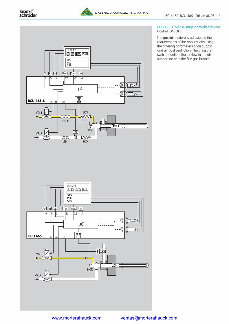
BCU 465..L: Single-stage-controlled burnerControl: ON/OFF.
The gas/air mixture is adjusted to the requirements of the applications using the differing parameters of air supply and air post ventilation. The pressure switch monitors the air flow in the air supply line or in the flue gas branch.
www.morterahauck.com [email protected]

6 · BCU 460, BCU 465 · Edition 08.07
BICR
VG..L
VR..R
BCU 465..L 12
23
SPSPLCCPE
DI
L1, N, PE
µC
P22 4
1918
1716
A
P
53
DI
6
26 21
BCU 465..L: Single-stage-controlled burner with pneumatic groupControl: ON/OFF.
The BCU supports the cooling and purg-ing processes. The variable air/gas ratio control compensates for gas/air pressure fluctuations. Optional: The pressure switch monitors the air flow during pre-purge and operation. The gas/air mixture is adjusted to the requirements of the ap-plications using the differing parameters of air supply and air post ventilation.
www.morterahauck.com [email protected]
BCU 460, BCU 465 · Edition 08.07 · 7
Technical dataMains voltage: 230 V AC, -15/+10%, 50/60 Hz, 115 V AC, -15/+10%, 50/60 Hz (option).
Length of burner cables: max. 5 m.
Max. number of operat-ing cycles: 1,000,000.
Ambient temperature: -20 to +60°C, no condensation permitted.
Enclosure: IP 54 pursuant to IEC 529.
Die-cast aluminium housing with plug-in terminal blocks and plug-in M20 cable glands.
Certification
The burner control units BCU 460 and BCU 465 are designed for applications pursu-ant to the Machinery Directive (98/37/EC).
EC type-tested and certified pursuant to
– Gas Appliances Directive (90/396/EC) in conjunction with EN 298
– Low Voltage Directive (73/23/EEC) in conjunction with EN 60730
– Electromagnetic compat-ibility (89/336/EEC)
AGACertified under no. 6478
FMBCU..T is FM-approved.
Standard: Factory Mutual Research Standard 7610: June 1997
Suitable for applications pur-suant to NFPA 86
(BCU..T see www.docuthek.com)
Profibus User OrganisationBCU..B1
PNO = PROFIBUS user organisation, Certifi-cate no. Z 00692 pursuant to EN 50170-2
www.morterahauck.com [email protected]
8 · BCU 460, BCU 465 · Edition 08.07
Kromschröder, a product brand of the Elster Group
Detailed information on this productwww.docuthek.com
Contactwww.kromschroeder.com ➔ Sales
Elster GmbH Postfach 2809 · 49018 Osnabrück Strotheweg 1 · 49504 Lotte (Büren) Germany
T +49 541 1214-0 F +49 541 1214-370 [email protected]
www.kromschroeder.com www.elster.com
We reserve the right to make technical modifications in the interests of progress.
Copyright © 2007 Elster Group All rights reserved.
0325
0379
F.T
08.
07 X
.XXX
SelectionBCU 460: standard version BCU 465: with extended air control
-3 -5 -10 /1 /2 L* 5* 15* 25* W R 1* 2* 3* 8* GB P* D2* D3* S2 – 4** A* U* C* B1* /1*BCU 460 ● ● ● ● ● ● ● ● ● ● ● ● 1) 1)
BCU 465 ● ● ● ● ● ● ● ● ● ● ● ● ● 1) ● 1)
Type = BCUSafety time on start-up tSA [s] = 3; 5; 10Safety time during operation tSB [s] = 1; 2Air valve control = L*Low fire over run time [s] = 5*; 15*; 25*Mains voltage 230 V AC, -15/+10%, 50/60 Hz = W 115 V AC, -15/+10%, 50/60 Hz = RIgniton transformer TZI 5-15/100 = 1* TZI 7-25/20 = 2* TZI 7.5-12/100 = 3* TZI 7.5-20/33 = 8*Front film in English with additional stickers in D, F, I, NL, E = GBIndustrial plug connector* = P*High temperature operation in conjunction with ...
... UVS = D2*
... ionisation sensor or UVD = D3*Number of start-up attempts = S2 – 4**Air flow monitoring = A*Preparation for UV sensor for continuous operation UVD 1 = U* Additional signal distribution = C*For PROFIBUS-DP = B1*9-pin D-Sub bus connector, IP 54 = /1*
* If “none”, this specification is omitted. ** If 1 start-up attempt, this specification is omitted. 1) Not in conjunction with PROFIBUS-DP = B1
= standard = available
Order exampleBCU 465-5/1LW3DAC
www.morterahauck.com [email protected]
6.1.2.7 03.11
AGA
Technical Information · GB
www.kromschroeder.com
• Easy transmission of activation signals and feedbacks via fieldbus cable
• Remote servicing and diagnostics facilities• Saves installation and wiring costs• Units can be exchanged during bus mode operation
thanks to industrial plug connector system (SUB-D)• Bus interface remains in operation when BCU® is
switched off (standby mode)• Certification for PROFIBUS-DP
Burner control unit for PROFIBUS-DP BCU 400..B1
www.morterahauck.com [email protected]

BCU 400..B1 · Edition 03.11
3
BCU 400..B1
1 ApplicationBCU 460..B1, BCU 460..L..B1, BCU 465..L..B1 and BCU 480..B1 correspond to the standard version in terms of their scope of functions and performance and, in addition, they can be equipped for connection to the PROFIBUS-DP fieldbus (see Technical Information bulletin BCU 460, BCU 465 and bro-chure BCU).The conventional wide-spread systems used in industrial fur-nace and kiln construction require bridging of large distances for signal processing.As a standardised fieldbus system, the PROFIBUS-DP consider-ably reduces development, installation and commissioning costs compared to conventional wiring.The use of a standard bus system offers massive benefits over manufacturer-specific bespoke solutions. Time-tested hardware components, standardised connection methods and a series of tools of bus diagnostics and optimisation are available on the market from a whole range of manufacturers. The widespread use of the system ensures that the planning and service personnel are very familiar with how the system operates and how to handle it and can therefore operate the system efficiently.
In addition to the scope of functions and performance
of the standard versions, the BCU..
B1 is also equipped with a connection for the PROFIBUS-
DP fieldbus.
www.morterahauck.com [email protected]

BCU 400..B1 · Edition 03.11
10
3.9 Fault messagesFault message (blinking) DISPLAY BCU 460..B1 BCU 465..B1 BCU 480..B1
Flame simulation 1
Start-up without flame signal 2
Flame failure during flame proving period 3
Flame failure during operation 4
Too many remote resets 10
Fault Air monitor break contact check 0
Fault Air supply during purging P
Fault Air supply in program step X X **
Fuse F1 defective or safety interlocks discontinuity 51
Permanent remote reset 52
Timing cycle too short 53
Bus fault P
System fault flickers*
EEPROM data change, NFS*** 30
EEPROM data change, FS*** 31
Undervoltage in power pack 32
Faulty parameterisation 33
Bus module fault E In manual mode, two dots blink on the display.
* Display flickers = BCU system fault.** x = 1, 2, .... or 8, depending on the program status/position step. For example, for a missing pressure switch input signal
in parameter/position step “Operation”, the display indicates 4 .*** FS = input/output safety circuit, NFS = input/output control system.For a detailed list of the fault messages, see Technical Information bulletin BCU 460, BCU 465 and brochure BCU.
Function
www.morterahauck.com [email protected]

BCU 400..B1 · Edition 03.11
18
5 SelectionBCU 460: Standard version; BCU 465: With extended air control; BCU 480: For pilot and main burner monitoring
-3 -5 -10 /-3* /-5* /-10* /1 /2 L* 5 15 25 W R 1 2 3 8 GB D2* D3* S2 – 4** A* C* B1* /1*BCU 460
BCU 465
BCU 480
Type = BCU1st safety time on start-up tSA [s] = 3; 5; 102nd safety time on start-up tSA [s] = 3*; 5*; 10*Safety time during operation tSB [s] = 1; 2Air valve control = L*Low fire over run time [s] = 5; 15; 25Mains voltage 230 V AC, -15/+10%, 50/60 Hz = W 115 V AC, -15/+10%, 50/60 Hz = RIgnition transformer TZI 5-15/100 = 1 TZI 7-25/20 = 2 TZI 7,5-12/100 = 3 TZI 7,5-20/33 = 8Front film in English with additional stickers in D, F, I, NL, E = GBDigital input to interrupt the flame monitoring... ... for continuous operation = D3* ... for intermittent operation = D2*Number of start-up attempts = S2 – 4**Air flow monitoring = A*Additional signal distribution = C*For PROFIBUS-DP = B1*9-pin D-Sub bus plug connector = /1*
Order example: BCU 465-5/1LW3GBACB1/1
= standard, = available, * if “none”, this specification is omitted, ** if 1 start-up attempt, this specification is omitted.Please quote the default Parameter settings when ordering.
www.morterahauck.com [email protected]

BCU 400..B1 · Edition 03.11
22
8 Technical dataMains voltage: 230 V AC, -15/+10%, 50/60 Hz, 115 V AC, -15/+10%, 50/60 Hz, For grounded and ungrounded mains.Power consumption: approx. 9 VA plus inherent consump-tion of the ignition transformer.Voltage to inputs and valves = mains voltage.Signal and control line: max. 2.5 mm2.Cable for burner earth/PE wire: 4 mm2.Input voltage Signal inputs:
115 V AC 230 V ACSignal „1“ 80 – 126,5 160 – 253Signal „0“ 0 – 20 0 – 40
Input current signal inputs:Signal “1”: typ. 2 mAOutput current:max. 2 A per output, but total current for valves and ignition transformer: max. 2.5 A.Fail-safe inputs and outputs: All the inputs and outputs marked „ “ (see connection dia-grams) may be used for safety tasks.Flame control: Sensor voltage: approx. 230 V AC. Sensor current: > 1 μA, Length of sensor cable: max. 5 m.
Fuse in unit: F1: 3.15 A, slow-acting, H, pursuant to IEC 127-2/5, F3: 3.15 A, slow-acting, H, pursuant to IEC 127-2/5 (for BCU..C).Operation and fault signalling contacts: Signalling contact (not floating); max. 2 A, 264 V, not inter-nally fused.Max. number of operating cycles: 1,000,000.Mains switch: 1000.Reset/Information button: 1000.Ambient temperature: -20 to +60°C, no condensation per-mitted.Enclosure: IP 54 pursuant to IEC 529.Weight: approx. 5 kg depending on version.
8.1 BCU..B1External fuse: 12 A per zone.
8.2 PROFIBUS-DPManufacturer ID: 0x05DB.ASIC type: SPC3.SYNC- and FREEZE-capable.Baud rate detection: Automatic.Min. cycle time: 0.1 ms.Diagnostic bytes: 6 (DP Standard).Parameter bytes: 7 (DP Standard).
www.morterahauck.com [email protected]
6.1.3.2 Edition 12.05Product brochure · GB
www.kromschroeder.com
Burner control unit BCU 370
For modulating, forced draught burners for gas of unlimited •capacity in intermittent or continuous operation
Control of fan and butterfly valve•
Simple system set-up thanks to optional tightness control •and integrated ignition unit
Easy start-up and maintenance thanks to Manual operating •mode
Enhanced flexibility and simplified logistics thanks to •programmable functions
Easy servicing thanks to informative operating, warning and •fault messages
Optionally available with integral field bus interface for •simple wiring
EC type-tested and certified, CSA and FM approved•
www.morterahauck.com [email protected]

2 · BCU 370 · Edition 12.05
Burner control unit BCU 370.
ApplicationThe BCU 370 burner control unit controls, ig-nites and monitors industrial forced draught burners of unlimited capacity in intermittent or continuous operation.
It can be used for directly ignited forced draught burners or forced draught burn-ers ignited with pilot burner. The BCU 370 activates the blower and sets the connected butterfly valve to pre-purging and ignition position. After pre-purge and burner start, the Enable signal is issued to an external controller which positions the butterfly valve in accordance with the output demand. Post-purge occurs after the end of burner operation. The burner control unit BCU 370 monitors the gas and air pressure. An op-tionally integrated tightness control function checks the valves with an external gas pres-sure switch.
Programmability by means of the optical interface and BCSoft PC software guaran-tees optimum adaptation to the relevant ap-plication. Adjustable start-up attempts and automatic restart which can be activated ensure the high availability of the burner equipment.
The quick-start option allows standard-com-pliant start-up of the forced draught burner without pre-purge after normal shutdown. This avoids unnecessary admission of air into the combustion chamber. The heat output is available as quickly as possible after a temperature demand.
The program status, the unit parameters and the level of the flame signal can be read di-rectly from the unit. An integrated Manual mode allows manual start of the burner and setting of the butterfly valve position inde-pendently of the central control system. The BCSoft operator-control and setting software provides a powerful tool for start-up and servicing.
To reduce the installation and wiring costs Kromschröder offers an optional Profibus-DP interface to transfer the activation signals and feedbacks.
www.morterahauck.com [email protected]
BCU 370 · Edition 12.05 · 3
VG
IC 20B VA
GIK
L1
V14
DG min
9 3
VG..L
V25 29 3130 32
23
21
24
131718
1920
262825BCU 370..I1
DL
DL7
DG
M
22
UVS
90°
� 0
0
� 9
0°
VG
IC 20B VA
GIK
L1
V14
DG min
9 3
VG..L
V25 32
23
21
24
131718
1920
25BCU 370..I1..D3
DL
DL7
DG
M
22
DG11
DGpe/2 UV
S
29 3130
2628
90°
� 0
0
� 9
0°
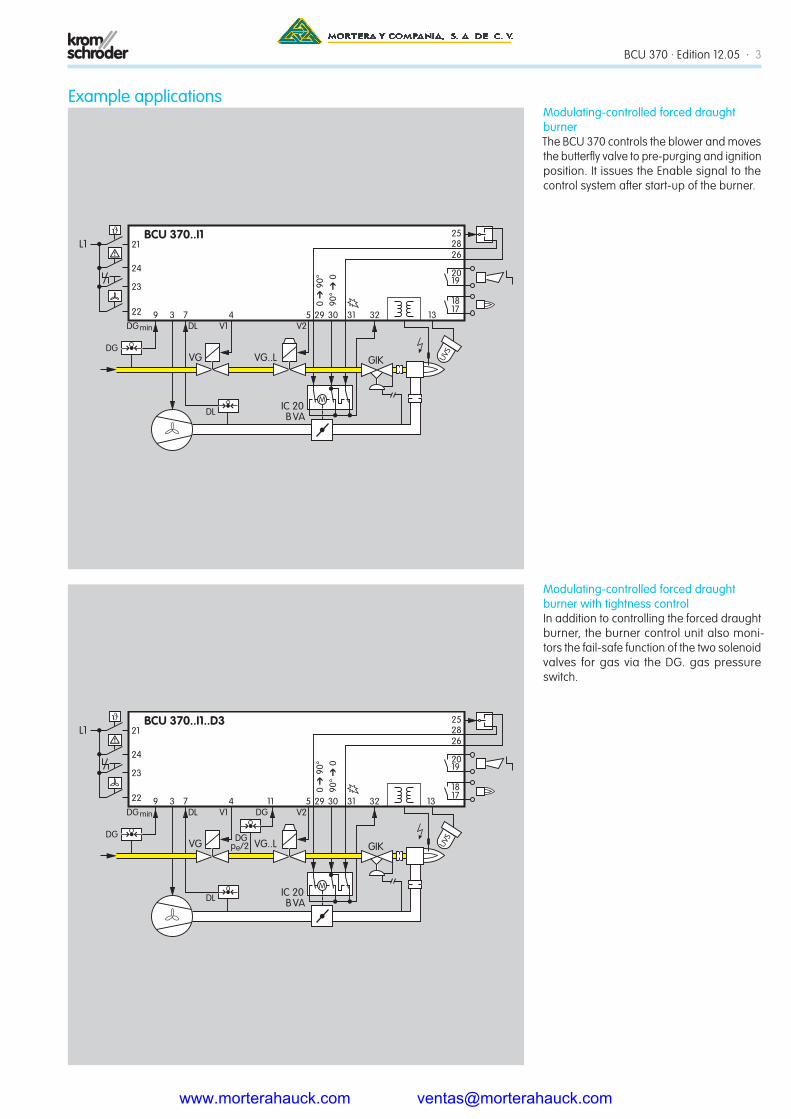
Modulating-controlled forced draught burner with tightness controlIn addition to controlling the forced draught burner, the burner control unit also moni-tors the fail-safe function of the two solenoid valves for gas via the DG. gas pressure switch.
Modulating-controlled forced draught burnerThe BCU 370 controls the blower and moves the butterfly valve to pre-purging and ignition position. It issues the Enable signal to the control system after start-up of the burner.
Example applications
www.morterahauck.com [email protected]
BCU 370 · Edition 12.05 · 4
VG
VG
IC 20B VA
GIK
L1
V1 V24 5
DG min
9 3
VG..L
V36 32
23
21
24
131718
1920
25BCU 370..D3
DL
DL7
DG
M
22
DG11
DGpe/2
UVS
29 3130
2628
90°
� 0
0
� 9
0°
Modulating-controlled forced draught burner with pilot burner and tightness controlA pilot burner ignites the main burner and is switched off during the main burner’s safety time.
www.morterahauck.com [email protected]

5 · BCU 370 · Edition 12.05
Technical dataMains voltage: BCU..W: 230 V AC, -15/+10%, 50/60 Hz, or BCU..Q: 120 V AC, -15/+10%, 50/60 Hz, for grounded or ungrounded mains.
Flame control with UV sensor or ionisation sensor.
Flame signal for: Ionisation control: 1 – 28 μA, UV control: 1 – 35 μA.
For intermittent or continuous operation.
Air pressure check during pre-purge and operation by external air pressure switch DL.
Maximum length of ignition cable with in-tegrated electronic ignition: 1 m.
Maximum length of ionisation/UV cable: 50 m (164 ft).
Max. number of operating cycles: 250,000.
Ambient temperature: BCU 370: -20 – +60 °C (-4 – +140 °F), BCU 370..I: -10 – +60 °C (14 – +140 °F), no condensation permitted.
Enclosure: IP 54 pursuant to IEC 529.
Housing made of impact-resistant and heat-resistant plastic. Plug-in upper sec-tion with operating and display elements.
Lower section with connection terminals, earthing strip and pre-wired neutral bus with spacious wiring chamber.
1x M25 multiple screw connector, 4x 7 mm cable grommets, 2x M20 multiple screw connectors, 2x 7 mm cable grommets, and loosely enclosed
1x or 2x M16 plastic screw connector(s) for the ignition cable(s).
Voltage to inputs, valves, fan, controller enable, actuator and ignition unit = mains voltage.
Power consumption: Approx. 9 VA plus ap-prox. 50 VA for integrated ignition.
Input voltage signal inputs:Rated value 120 V AC 230 V ACSignal “1” 80 – 126.5 V 160 – 253 VSignal “0” 0 – 20 V 0 – 40 V
Input current signal “1”: Typ. 2 mA
Output to ignition transformer: No-switch contacts via semi-conductor.
Contact rating: Valves: Max. 1 A, cos j = 1, Butterfly valves: Max. 1 A, cos j = 1, Ignition: Max. 1 A, cos j = 0.3, Controller enable signal: Max. 1 A, cos j = 1, the contacts may be loaded with a max. total of 2.5 A, Fan: Max. 3 A, start-up current: Max. 6.5 A < 1 s.
The outputs may be loaded with a max. total of 4 A.
Operation and fault signalling contacts: Dry Contact, max. 1 A, 253 V, not fused internally.
Reset/Information button: Max. number of operating cycles: 1000.
Fuse in BCU, replaceable, F1: T 5A H, pur-suant to IEC 60127-2/5.
Permissible UV sensors: Kromschröder models UVS 1, 5, 6, 8 and UVD 1.
Weight: Approx. 1.8 kg.
PROFIBUS-DPManufacturer ID: 0x08EC.
ASIC type: SPC3.
SYNC- and FREEZE-capable.
Baud rate detection: Automatic.
Min. cycle time: 0.1 ms.
Diagnostic bytes: 6 (DP Standard).
Parameter bytes: 7 (DP Standard).
CertificationEC type-tested and certifiedpursuant to
– Gas Appliances Directive (90/396/EEC) in conjunction with EN 298,
– Low Voltage Directive (73/23/EEC) in con-junction with the relevant standards,
– Electromagnetic compatibility 89/336/EEC in conjunction with the relevant standards relating to radiation.
AGAApproval No. 6478 in preparation
CSA and FM approvedCanadian Standards Association Class: 3335-01 and 3335-81 Systems (Gas-)Auto-matic Ignition and Components
Factory Mutual Research Class: 7611 Com-bustion Safeguards and Flame Sensing System
Suitable for applications pursuant to NFPA 85 and NFPA 86
PROFIBUS User OrganisationBCU 370..B1
PUO = PROFIBUS User Organisation,
Certificate no. Z 00692 pursuant to EN 50170-2
www.morterahauck.com [email protected]

6 · BCU 370 · Edition 12.05
Kromschröder, a product brand of the Elster Group
Detailed information on this productwww.docuthek.com
Contactwww.kromschroeder.com Sales
Elster GmbH Postfach 2809 · 49018 Osnabrück Strotheweg 1 · 49504 Lotte (Büren) Germany
T +49 541 1214-0 F +49 541 1214-370 [email protected]
www.kromschroeder.com www.elster.com
We reserve the right to make technical modifications in the interests of progress.
Copyright © 2007 Elster Group All rights reserved.
0325
0459
Dru
cker
ei M
M.J
J X
.XXX
SelectionBCU 370: for modulating-controlled forced draught burners
W Q I1 I2 I3 F E U0 U1 D1 D3 B1* -3*BCU 370 ** **
Type = BCUMains voltage 230 V AC, 50/60 Hz = W 120 V AC, 50/60 Hz = QIgnition Electronic ignition, single-pole = I1 Electronic ignition, double-pole = I2** Electronic ignition, double-pole with neutral conductor = I3** Without ignition = no specificationFan control = FValve control = EFlame control Ionisation control (continuous or intermittent op.) or UV control (intermittent op. with UVS) = U0 UV (continuous operation with UVD 1) = U1DGmax. monitoring = D1 Integrated tightness control = D3For PROFIBUS-DP = B1*Three-point step control via PROFIBUS-DP = -3*
* If “none”, this specification is omitted. ** I2 only for 230 V, I3 only for 120 V
Order exampleBCU 370WI1FEU0D1 = standard
= available
www.morterahauck.com [email protected]