BUREAU OF RECLAMATION HYDRAULIC LABORATORY … · BUREAU OF RECLAMATION HYDRAULIC LABORATORY . ......
17
PA10- // DF/=fcF FILE COPY BUREAU OF RECLAMATION HYDRAULIC LABORATORY HYDRAULICS BRANCH OFFICIAL FILE COPY On. .9
Transcript of BUREAU OF RECLAMATION HYDRAULIC LABORATORY … · BUREAU OF RECLAMATION HYDRAULIC LABORATORY . ......

PA10- // DF/=fcF
FILE COPY BUREAU OF RECLAMATION
HYDRAULIC LABORATORY
HYDRAULICS BRANCH OFFICIAL FILE COPY
On.
.9

PROTOTYPE BEHAVIOR OF MORNING-GLORY SHAFT SPILLWAYS
0 J. N. Bradley
Engineer, Bureau of Reclamation Design and Construction Division
Denver, Colorado
A paper for the Summer Convention, ASCE, Denver, Colorado, June 1952


PROTOTYPE BEHAVIOR .OF MORNING-GLORY SHAFT SPILLWAYS
J. N. Bradley, Assoc, M. ASCE 1/
This is the first of three talks on morning-glory shaft spillways. The first lecture will be of a general nature, while the following two will deal with specific problems. The second talk will deal with the shaping of the morning-glory portion of the spillway, and the third lecture will con-sist of an account of experiences and observations at the Heart Butte and Shadehill Dam spillways operating under flood conditions.
This talk will deal with an investigation of prototype behavior of morning-glory shaft spillways. We will begin with a short discussion of the general features of this type of spillway as an introduction to all three talks
The morning-glory shaft spillway is comprised of three essential parts. a collecting structure or the morning-glory proper, a vertical or inclined shaft, and a horizontal tunnel, In some cases, a stilling basin is constructed at the downstream end of the horizontal tunnel, Usually., a vertical shaft is used and this is connected to the horizontal tunnel through a rather sharp 900 bend, In fact, in only two cases on record have inclined shafts been used.
The morning-glory spillway may operate with free flow or, de-signed properly, it can operate submerged. For free flow, the discharge characteristics are similar to those for a straight overfall dam section, where an increase of discharge is proportional to the three halves power of the head. When operated submerged, the flow characteristics change com-pletely, An increase in discharge is then proportional to the square root of the head but, if part of the shaft flows full, the effective head may exceed the head measured above the crest. A point to be remembered is that, once submerged flow occurs, a further increase in head on the crest results in a very limited increase in discharge. Thus, if a morning-glory spillway is designed to operate submerged, an additional factor of safety should be ap-plied to flood predictions to guard against the spillway capacity ever being exceeded,
The morning-glory spillway is attractive in that it can often be con-structed at less cost than other types; it is readily adaptable to dams in nar-row steep canyons; and where a diversion tunnel is used to conduct the river around the site during construction, it can do double duty by serving as a portion of the spillway tunnel, When designed to operate submerged, this type of spillway serves well for retention reservoirs where the flow down-stream is to be limited
1/ Hydraulic ngineer, _sign and Construction Division, Bureau of Reclamation, Denver, Colorado.

The principal drawback is the fact that information is quite meager on prototype operation of these structures, Consequently, designers have had a tendency to shy away from the morning-glory spillway if some other type will do,
The design is sound from a hydraulic standpoint, The question-able factors are structural, namely: Will the concrete or other material composing the curved surface of the vertical bend and horizontal tunnel withstand the velocities and scaling effects of the fast-moving water? Will ice or debris present difficulties in operation? Will vibration or noise be-come objectionable?
With the construction of the Heart Butte Dam spillway, which. con-sists of a morning-glory designed for submerged flow with as much as 54 feet of head on the crest, and the design of the Hungry Horse Dam spillway, which will feature a total drop of 475 feet from headwater to tail water, the above questions take on added significance. For example, vibration of the Heart Butte spillway, which is embedded directly In the earth dam, would create a serious situation. Erosion of the tunnel lining in the Hungry Horse spillway at the very high velocities contemplated would produce intolerable difficulties,
In an attempt; to partially clarify some of these questions in light of prototype experience, a questionnaire was sent to persons connected with morning-glory shaft spillways throughout the world, The text of the questionnaire varied, but these three questions were common to all of them:
la Has any erosion of the concrete been experienced in the tunnel, especially in the vicinity of the vertical elbow?
2 0 Has objectionable vibration or noise been noticeable in the structure during operation?
3. Has any difficulty been experienced in the passing of debris or ice ?
The response and cooperation received in reply to this inquiry were ex-cellent, As to the value of the information collected, you may be the judge.
As far as it is possible to determine, there are approximately 25 true morning-glory shaft spillways .either in existence or under construction today, The first morning-glory spillway was built in :1896, designed by James 1Vlansergh, for the Blackton Reservoir, England. The second morning-glory spillway on record was built in 1916, at the Taf Fechan Dam in Wales. The remaining 23 spillways have been constructed since 1925. This would indicate that the morning-glory spillway is a rather recent innovation;, or it may indicate that the designer has played safe by avoiding it, It is in-teresting to note that model studies have been made to aid in the design of practically all of the morning-glory spillways, dating back to 19160 Un-fortunately, model studies do not tell all that is desired,

Why the anxiety over morning-glory spillways? The following example should illustrate the point: The Arizona spillway at Hoover Dam, which has a fall of approximately 570 feet, went into operation for the first time in August 1941. A week later, the gates were raised and a hurried inspection was made of the tunnel. No erosion was apparent, and operation was continued until December of the same year. The average flow during the 4-month period was 13, 500 cfs. The maximum flow was 38, 000 cfs, which lasted for only a few hours. At the end of this period, a hole was discovered 115 feet long, 30 feet wide, and 45 feet below in- vert grade, immediately downstream from the vertical bend. The veloc- ity was approximately 150 feet per second. The spillway was designed for 200, 000 cfs, so the average flow was about 7 percent of capacity. You have probably heard this story before, but we have not forgotten it.
The Hoover Dam spillways are not the morning-glory type, but the tunnel arrangement is similar to some morning-glory spillways. There are a number of theories as to what actually happened at Hoover Dam, but nothing conclusive. In short, there was a misalignment of the invert of the tunnel, there was evidence of cavitation, and the large hole is indicative of impact and scaling. This we do not want to happen again in any structure. But a question presents itself: If. this can happen to an inclined shaft, what can be expected in the case of a vertical shaft terminating in a sharp 900 bend ?
On the other side of the ledger, we can cite experiences .relative to the spillway at Fontana Dam of the TVA which was completed in 1945. The Fontana Dam was in the process of design at the time of the incident at Hoover Dam, so special care was exercised in the tunnel design. This spillway also is not the morning-glory type, but it has an inclined tunnel with a fall of 410 feet, 160 feet less than at Hoover Dam. It has operated every year since its completion and has carried discharges of 20, 000 cfs, or approximately one-ninth of capacity. Nothing but roughened surfaces have been evident to date.
Now for the results of the investigation of morning-glory shaft spillways. Starting with the Taf Fechan morning-glory spillway in Wales, which is the earliest one on which there is any concrete information, you may get a picture of the evolution of this type of spillway as well as infor-mation on prototype operation. The Taf Fechan (Figure 1) was designed in 1916 to handle a maximum discharge of 3, 000 cfs. The drop from head-water to tail water is about 100 feet, with a maximum head of 2. 8 feet of head over the crest. The design is sound--in fact greatly overdesigned by present standards. The long sweeping curves of the early designs are very suggestive of the morning-glory flower. Correspondence, with the late W. J. E. Binnie, who acted as consultant on the Taf Fechan job, indicates that no trouble has been experienced with this spillway and no unusual re-pairs have been required. It is interesting to note the presence of the anti-vortex device on this early spillway.
There is no record of a morning-glory spillway being built for the next 10 years, but there were 10 constructed between 1925 and 1931. The
3
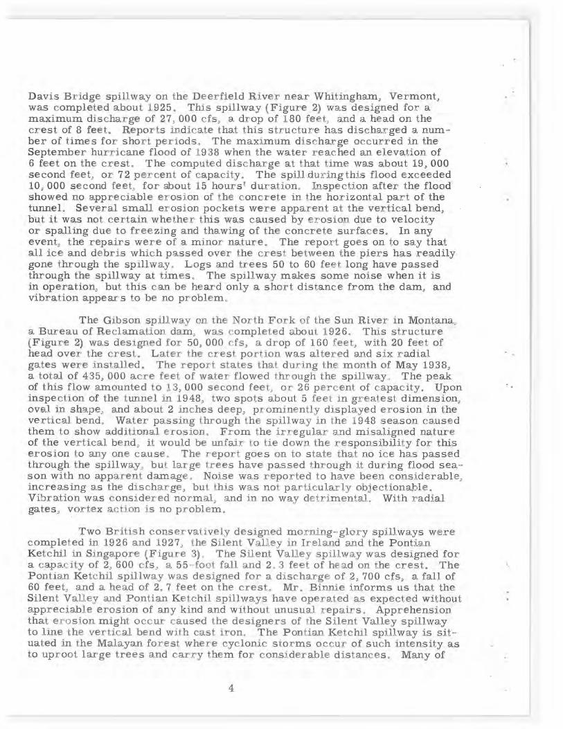
Davis Bridge spillway on the Deerfield Raver near Whitingham, Vermont, was completed about 1,925. This spillway (Figure 2) was designed for a maximum discharge of 27, 000 cfs, a drop of 180 feet, and a head on the crest of 8 feet, Reports indicate that this structure has discharged a num-ber of times for short periods, The maximum discharge occurred in the September hurricane flood of 1938 when the water reached an elevation. of 6 feet on the crest. The computed discharge at that time was about 19, 000 second feet, or 72 percent of capacity, The spill.dur°angthis flood exceeded 10, 000 second feet, for shout 15 hours' duration. Inspection after the flood showed no appreciable erosion. of the concrete in the horizontal part of the tunnel. Several small erosion pockets were apparent at the vertical bend, but it was not certain whether this was caused by erosion due to velocity or spallin.g due to freezing and thawing of the concrete surfaces. In any event, the repairs were of a minor nature. The report goes on to say that all ace and debris which passed over the crest between the piers has readily gone through the spillway. Logs and trees 50 to 60 feet long have passed through the spillway at times. The spillway makes some noise when at as
an operation, but this can be heard only a short distance from the dam, and vibration appears to be no problem,
The Gibson spillway on the North Fork of the Sun River in. Montana, a Bureau of Declamation dam, was completed about 1926, This structure (Figure 2) was designed for 50, 000 cfs, a drop of 160 feet, with 20 feet of head over the crests Dater the crest portion was altered and sax radial, gates were installed. The report states that during the month of May 1938, a total, of 435, 000 acre feet; of water flowed through the spillway. The peak of this flow amounted to 13, 000 second feet, or 26 percent of capacity, Upon inspection of the tunnel an 1948, two spots about 5 feet an greatest dimension oval in shape, and about 2 inches deep: prominently displayed erosion in the vertical bend. Water passing through the spillway an the 1948 season. caused them to show additional erosion. From the irregular and misaligned nature of the vertical bend, at would be unfair to tie down the responsibility for this erosion to any one cause, The report goes on to state that no ice has passed through the spillway, but large trees have passed through it during flood sea-son with no apparent damage. Noise was reported to have been considerable, increasing as the discharge, but this was not particularly objectionaj-)leo Vibration was considered normal, and in no way detrimental. With radial gates, vortex action is no problem,
Two British conservatively designed morning-glory spillways were completed an. 1926 and 1927, the Silent Valley in Ireland and the Pontaa.n Ketchil an Singapore (Figure 3)o The ,Silent Valley spillway was designed for a capacity of 2, 600 efs, a 55-root fall and 20 3 feet of head on the crest, The Pon.tian Ketchil spillway was designed for a discharge of 2, 700 cfs, a fall. of 60 feet, and a head of 2, 7 feet on the crest. Mr. Binnie informs us that the Silent Valley and Pontlan Ketchil spillways have operated as expected without appreciable erosion of any kind and without unusual repairs, Apprehension. that erosion might occur caused the designers of the Silent Valley spillway to line the vertical bend with cast iron. The Pontian. Ketchil spillway is sat-n
uated in the Malayan forest where cyclonic storms occur of such intensity as to uproot: large trees and carry them for considerable distances, Many of
11

' y 3
SECTION
TAF FECHAN
/ 4800
4775
E1.4711.5 4750
4725 DIA. ----- - - - --- --
4700
4673
MAX. W.S. E1.4724'~ P L A N
PLAN MAX.W.S:Y 12.5 E1.47042. -
-16 PIERS x 8 -: a Y-- :o x
61 5 DIA. -- El .4676
77.31' 36' DIA.- -" 22.5' DIA. ,-El.4623.75
a. a 154.2' 102.42' 29.5' DIA.- .59'R.
55' R.- ~--
29.5' DIA. J El. -- r 22.5' DI Am, —-21.5' DIA. , ------------
SECTION SECT10 N
DAVIS BRIDGE B. GIBSO N
Mox. W.S: •,
2.6'-" .o
66'Dia: - '
4' Fins 9" wide 0
Z N'~ L
i i
Figure 1 Figure 2

Mnv W S - a5 Piers 10"wide x 3' long
2.3'-- r in
Max WS 80, 010
4 Fins 9'1►nQe
16'•Dia.
5EGTI0N
PONTIAN KETCHIL
SECTION SILENT VALLEY
Figure 3
27•..___., i
0 6 Pit
N.
.Max WS s
30'bio
A --Curtain 10
wall- e
4 Fins originally intended_
N 2ss~
12~.0
17'ID,o
m
P
l
SEZTION SECTION
BURNHOPE MANUHERIKIA FALLS
Figure 4
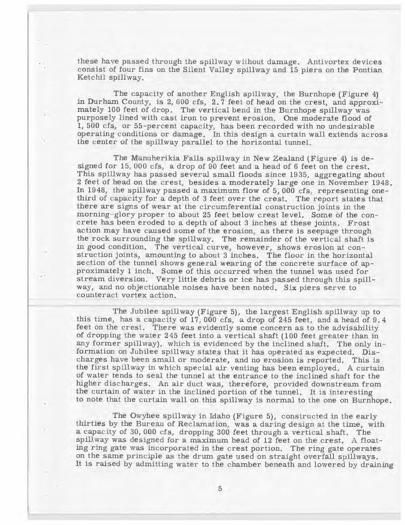
these have passed through the spillway without damage. Antivortex devices consist of four fins on the Silent Valley spillway and 15 piers on the Pontian Ketchil spillway.
The capacity of another English spillway, the Burnhope (Figure 4) in Durham County, is 2, 600 cfs, 2. 7 feet of head on the crest, and approxi-mately 100 feet of drop. The vertical bend in the Burnhope spillway was purposely lined with cast iron to prevent erosion. One moderate flood of 1, 500 cfs, or 55-percent capacity, has been recorded with no undesirable operating conditions or damage. In this design a curtain wall extends across the center of the spillway parallel to the horizontal tunnel,
The Manuheri.kia Falls spillway in New Zealand (Figure 4) is de-signed for 15, 000 cfs, a drop ,of 90 feet and a head of 6 feet on the crest. This spillway has passed several small floods since 1935, aggregating about 2 feet of head on the crest, besides a moderately large one in November 1948. In 1948, the spillway passed a maximum flow of 5, 000 cfs, representing one-third of capacity for a depth of 3 feet over the crest. The report states that there are signs of wear at the circumferential construction joints in the morning-glory proper to about 25 feet below crest level. Some of the con-crete has been eroded to a depth of about 3 inches at these joints. Frost action may have caused some of the erosion, as there is seepage through the rock surrounding the spillway. The remainder of the vertical shaft is in good condition. The vertical curve, however, shows erosion at con-struction joints, amounting to about 3 inches, The floor in the horizontal section of the tunnel shows general wearing of the concrete surface of ap-proximately 1 inch, Some of this occurred when the tunnel was used for stream diversion., Very little debris or ice has passed through this spill-way, and no objectionable noises have been noted. Six piers serve to counteract vortex actions
The Jubilee spillway (Figure 5), the largest English spillway up to this time, has a capacity of 17, 000 cfs, a drop of 245 feet, and a head of 9, 4 feet on the crest. There was evidently some concern as to the advisability of dropping the water 245 feet into a vertical shaft (100 feet greater than in any former spillway), which is evidenced by the inclined shaft. The only in-formation on Jubilee spillway states that it has operated as expected. Dis-charges have been small or moderate, and no 'erosion is reported. This is the first spillway in which special air venting has been employed. A curtain of water tends to seal the tunnel at the entrance to the inclined shaft for the higher discharges. An air duct was, therefore, provided downstream from the curtain of water in the inclined portion of the tunnel. It is interesting to note that the curtain wall on this spillway is normal to the one on Burhhope,
The Owyhee spillway in Idaho (Figure 5); constructed in the early thirties by the Bureau of Reclamation, was a daring design at the time, with a capacity of 30, 000 cfs, dropping 300 feet through a vertical shaft. The spiD,way was designed for a maximum head of 12 feet on the crest. A float- ing ring gate was incorporated in the crest portion. The ring gate operates on the same principle as the drum gate used on straight overfall spillways® It is raised by admitting water to the chamber beneath and lowered by draining
5
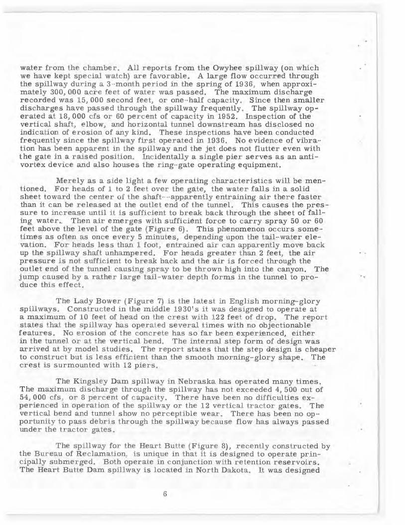
water from the chamber. All reports from the Owyhee spillway (on which we have kept special watch.) are favorable, A large flow occurred through the spillway during a 3-month period in the spring of 1936, when approxi-mately 300, 000 acre feet of water was passed, The maximum discharge recorded was 15, 000 second feet, or one-half capacity. Since then smaller discharges have passed through the spillway frequently. The spillway op-erated at 18, 000 cfs or 60 percent of capacity in 1952. Inspection. of the vertical shaft, elbow, and horizontal tunnel downstream has disclosed no indication, of erosion of any kind. These inspections have been conducted frequently since the spillway first operated in 1936. No evidence of vibra-tion has been apparent in the spillway and the jet does not flutter even with the gate in a raised position, Incidentally a single pier serves as an anti-vortex device and also houses the ring-gate operating equipment.
Merely as a side light a few operating characteristics will be men-tioned. For heads of 1 to 2 feet over the gate, the water falls in a solid sheet toward the center of the shaft--apparently entraining air there faster than it can be released at the outlet end of the tunnels This causes the pres-sure to increase until it is sufficient to break back through the sheet of fall-ing water,. Then air emerges with sufficient force to carry spray 50 or 60 feet above the level of the gate (Figure 6)o This phenomenon occurs some-times as often as once every 5 minutes, depending upon the tail-water ele-vation. For heads less than 1 foot, entrained air can apparently move back up the spillway shaft unhampered. For heads greater than 2 feet, the air pressure is not sufficient to break back and the air is forced through the outlet end of the tunnel causing spray to be thrown high into the canyon. The jump caused by a rather large tail-water depth forms in the tunnel to pro-duce this effect,
The Lady Bower (Figure 7) is the latest in English morning-glory spillways. Constructed in the middle 1930°s it was designed to operate at a maximum of 10 feet of head on the crest with 122 feet of drop. The report states that the spillway has operated several times with no objectionable features. No erosion of the concrete has so far been experienced, either in the tunnel or at the vertical bend, The internal. step form of design was arrived at by model studies. The report states that the step design is cheaper to construct but is less efficient than the smooth morning-glory shape. The crest is surmounted with 12 piers,
The Kingsley Dam spillway in Nebraska has operated many times. The maximum discharge through the spillway has not exceeded 4, 500 out of 54, 000 efs, or 8 percent of capacity. There have been no difficulties ex-perienced in operation of the spillway or the 12 vertical tractor gates. The vertical bend and tunnel_ show no perceptible wears There has been no op-portunity to pass debris through the spillway because flow has always passed under the tractor gates
The spillway for the Heart Butte (Figure 8), recently constructed by the Bureau of Reclamation, is unique in that it is designed to operate prin-cipally submerged. Both operate in conjunction, with retention reservoirs. The Heart Butte Dam spillway is located in North Dakota, It was designed

I. I nT. . \, 0 — I ki I ki r
"MAX. W. S. PLAN /// T-' 2150
MAX. W.S. PLA N El. 2670 60'x 12
9.35' Y 74 D I A-. --------- RING GATE
-E1.2658
27 5 Dl;~.-- ',f 25' DIA.- R. 30.7 - AIR VENTS
245' 22.6'DIA.--J~
43.3 3'R. -30'R. • J1.2410.3
309
15 AIR S LOT 50'R.
E1.2349 SECTION 1-22.6'DIA.:
•
-7yT -----------
SECTION JUBILEE ----------- ------ OWYHEE
Figure 5
I
Figure 6

MOM
I
FPM Of doN..
PLAN
G ~
r•
wft
u .
W KINGSL[Y
32.5' DIA.--,
MAX. W.S. PLAN El. 2118.1
------ E1.2078.5 1
- 27' DIA. -'EI20645
jr-EI.2053.85 11.67' DIA.
AIR VENTS- E1.2033
II' DIA. 59.5'
21'R.
-14' DIA. Y i
SECTION
HEART BUTTE
Figure 7 Figure 8

for a capacity of 5, 600 cfs, with a drop from headwater to tail water of 106 feet, and operates submerged at a maximum head of 54 feet on the crest. Free flow occurs for heads up to 6 feet. Submerged flow occurs for heads above 6 feet. A large vortex forms for heads from 6 to 20 feet, For heads from 20 to 54 feet, vortices are either small or nonexistent. The six piers on the crest serve to break up the large vortex into a num-ber of smaller ones reducing fluctuations in discharge and resulting in improved flow conditions. This dam was completed in 1949, and in the Spring of 1950 passed a major flood. The spillway operated for approxi-mately 1 month and passed 148, 000 acre feet of water. The maximum flow into the reservoir during the flood was 24, 000 cfs, while the maximum dis-charge released through the spillway amounted to 3, 800 cfs. An inspec-tion .after this floo3 showed erosion at two points in the vertical bend. In each case the eroded areas were about 8 inches in diameter and a maxi-mum of 1 inch deep. This spillway again went into operation in 1951 and 52.
Of the 25 morning-glory spillways in existence, only those which have operated have been mentioned. Incidentally, there have been two new morning-glory spillways recently completed, the Wautauga and South Holston, constructed by the TVA in Tennessee. Each has a capacity of about 60, 000 cfs and a drop of approximately 300 feet. Others are the Hungry Horse Dam spillway in Montana, capacity 50, 000 cfs and 475-foot fall; and several in Greece, Spain, and Portugal, all under construction.
Summing up the above prototype information, it can be said that at least 7 of the 25 spillways above have undergone a fair test.
The results of the investigation are by no means conclusive. The results are encouraging, however, in that°
1. No erosion of the concrete was reported at the vertical bend at Owyhee Dam. This spillway has, -,pperated often twice at half capacity. It has the greatest fall of any morning-glory spillway which has operated. Also, in no case has erosion of a serious nature occurred on any of the spillways investigated. It is quite conclusively believed that the small erosion patches which occurred at the vertical bend on at least 4 of the spill-ways were caused by logs falling down the shaft.
2. Vibration and noise have in no case been found to be sufficient to be considered objectionable.
3. In no case has debris or ice presented any unusual prob-lem in operation except with respect to impact at the vertical bend.
To date, the best method of cop2ng with erosion caused by high velocities, regardless of the type of structure, lies in maintaining smooth surfaces, outlawing misalignment, and eliminating construction joints in vertical bends. This is the reasoning and procedure followed at the present

time by the Bureau of Reclamation on all types of tunnel spillways. It stands to reason that once a surface has been roughened, it is more sus-ceptible to scaling, impact forces and cavitation when exposed to high velocity water.
In closing I would like to encourage the collection of data and the preparation of reports on the prototype operation of hydraulic structures. It is actually a small investment compared to the benefits which can be derived, What better method is there of detecting defects, of effecting economy and improvink future designs?
i
Interior - Reclamation - Denver, Colo.

kr
r
w