
Bundelkhand Institute of Engineering & Technology, Jhansi...
27
1 Bundelkhand Institute of Engineering & Technology, Jhansi Short Term Tender Notice No. BIET- 1/2017 The tender documents for the Purchase of Equipment of Electrical Engg. Deptt. Tender can be downloaded from the website, www.bietjhs.ac.in or can be obtained from the store & purchase section. A separate demand draft for the cost of tender documents is required along with tender documents. Tender opening and submission details are given below 1. Name of firm with contact number & Email address …………………………………………………………………………………………… …………………………………………………………………………………………… …………………………………………………………………………………………… …………………………………………………………………………………………… …………………………………………………………………………………………… …………………………………………………………………………………………… 2. Tender cost (Non refundable) is Rs. 2300/- 3. Tender submission is up to 28.03.2017 at 2:00 PM 4. Tender opening on 28.03.2017 at 2:30 P.M. 5. Opening place of tender is conference room, administrative block BIET Jhansi. Signature & Seal of Tenderer
Transcript of Bundelkhand Institute of Engineering & Technology, Jhansi...

1
Bundelkhand Institute of Engineering & Technology, Jhansi
Short Term Tender Notice No. BIET- 1/2017
The tender documents for the Purchase of Equipment of Electrical Engg. Deptt. Tender can be downloaded from the website, www.bietjhs.ac.in or can be obtained from the store & purchase section. A separate demand draft for the cost of tender documents is required along with tender documents.
Tender opening and submission details are given below
1. Name of firm with contact number & Email address ………………………………………………………………………………………………………………………………………………………………………………………………………………………………………………………………………………………………………………………………………………………………………………………………………………………………………………………………………………………………………………………………………………………………………………
2. Tender cost (Non refundable) is Rs. 2300/-
3. Tender submission is up to 28.03.2017 at 2:00 PM
4. Tender opening on 28.03.2017 at 2:30 P.M.
5. Opening place of tender is conference room, administrative block BIET Jhansi.
Signature & Seal of Tenderer

2
Bundelkhand Institute of Engineering & Technology, JHANSI (U.P.)
Department: Electrical Engineering
Particular of EMD
LAB No.
Lab EMD (In Rupees)
EE-1 Electrical Engineering Laboratory
10,000
EE-2 Electromechanical Energy Conversion Lab – I
13,000
EE-3 Electrical Measurement Lab
5,000
EE-4 Electromechanical Energy Conversion Lab – II
9,000
EE-5 Network Lab 3,000
EE-6 Electrical Instrumentation lab 5,000
EE-7 Power Electronics Lab
6,000
EE-8 Power system lab 30,000
EE-9 Electric drive lab 10,000

3
Detail of Specification of Electrical Engineering Laboratory
Sr. No
NAME OF EQUIPMENT QTY. Rates in Rupees
Cost in Rupees
1. Complete Setup For performing :-Verification of Kirchhoff’s laws (KVL/KCL)
02
2. Complete Setup For performing :- Verification of (i) Superposition theorem (ii) Thevenin’s Theorem (iii) Maximum Power Transfer Theorem.
02
3. Complete Setup For performing :-Measurement of power and power factor in a single phase ac series inductive circuit and study improvement of power factor using capacitor
02
4. Complete Setup For performing :- Study of phenomenon of resonance in RLC series circuit and obtain resonant frequency.
02
5. Complete Setup For performing :- Measurement of power in 3- phase circuit by two wattmeter method and determination of its power factor.
02
6. Complete Setup For performing :- Determination of parameters of ac single phase series RLC circuit
02
7. Complete Setup For performing :- Determination of (i) Voltage ratio (ii) polarity and (iii) efficiency by load test of a single phase transformer
02
8. Complete Setup For performing :- To measure energy by a single phase energy meter and determine error.
02
9. Complete Setup For performing :- To study P-N diode characteristics
02
10. Complete Setup For performing :- To study full wave and half wave rectifier circuits with and without capacitor and determine ripple factors.
02
11. Complete Setup For performing :- To study various logic gates (TTL)
02
12. Complete Setup For performing :- To study Operational Amplifier as Adder and Sub tractor
02
13. Complete Setup For performing :- To study transistor as a switch.
02
14. Rheostat up to 2000 Ohm,10Amp 10 15. DC Regulated Power Supply 0-30 Volt, 5Amp. 05 16. Bread Board With Power Supply ± 0-15 Volt in Box 05 17. Digital Multi-meter 05 18. C.R.O. up to 30 MHz 10 19. Complete Setup For performing :-
To Plot V-I characteristics of junction diode and zener diode. 02
TOTAL

4
ELECTROMECHANICAL ENERGY CONVERSION LAB – I
Sr. No.
NAME OF EQUIPMENT QTY. Rates in rupees Cost in Rupees
1. Complete Setup For performing :- To obtain magnetization characteristics of a DC Shunt Generator MACHINES REQUIRED D.C. Shunt Motor, 2 HP, 230 V, 1500 RPM, (Prime Mover) flexibly coupled to Shunt Generator 1.0 KW (self-excited). Both the machines flexibly coupled and mounted on M S channel base. D.C. SHUNT MOTOR : Type: DC Motor, shunt wound, self-excited, screen protected, horizontal foot mounted, fan cooled, provided with inter poles with DC starter face plate type. Capacity : 2 HP Winding : Shunt wound. R.P.M. : 1500 Volts. : 230 Insulation : Class ‘B’ Connections: All the terminals of armature and shunt field shall be brought over to a Bakelite sheet, fixed to C.I. terminal box, fitted on top of Motor. D.C. SHUNT GENERATOR : Type: DC Generator, Shunt wound, self-excited, screen protected, horizontal foot mounted, and fan cooled, provided with inter poles. Capacity : 1.0 KW, R.P.M. : 1500 Volts. : 230 Insulation : Class ‘B’ Connections: All the terminals of armature and shunt field shall be brought over to a Bakelite sheet, fixed to C.I. terminal box, fitted on top of Motor. Both the machines are flexibly coupled and mounted on sturdy m.s. channel base. The terminals of armature, shunt and series field windings of both the machines shall be brought over to Bakelite plate fixed on C.I. terminal box fitted on top of machine. CONTROL PANEL FOR MG SET : DC SHUNT MOTOR & DC SHUNT GENERATOR With All Measuring instruments required as per Experiment (Fitted on Engraved Bakelite sheet enclosed in almirah type M S box with lock & handle arrangement suitable for table mounting.)
1
2. Complete Setup For performing :- To obtain load characteristics of a D.C.. shunt generator and compound generator (a)Cumulatively compounded (b) Differentially compounded D.C. Power supply Fixed : 200 V Variable : 0-200 V DC Machine Type : DC Shunt
1

5
Rating : 1 HP RPM : 1500 (No Load) Tachometer :20,000 RPM With All Measuring instruments required as per Experiment (Fitted on Engraved Bakelite sheet enclosed in almirah type M S box with lock & handle arrangement suitable for table mounting.)
3. Complete Setup For performing :- To obtain efficiency of a dc shunt machine using Swinburne’s test Swinburne test of DC Machine:- Input Supply : 200 V Fixed DC : 0-200 V Variable DC DC Machine specification Type : DC Shunt Rating : 1 HP Voltage Rating : 200 Volt RPM : 1500 (No Load) With All Measuring instruments required as per Experiment (Fitted on Engraved Bakelite sheet enclosed in almirah type M S box with lock & handle arrangement suitable for table mounting.)
1
4. Complete Setup For performing :- To perform Hopkinson’s test and determine losses and efficiency of DC machine. Hopkinsontest of DC Machine:- Input Supply : 200 V Fixed DC : 0-200 V Variable DC DC Machine specification (2 Nos) Both the Machines are flexibly coupled and mounted on a M.S. channel base act as a Motor Generator set. Type : DC Shunt Rating : 1 HP Voltage Rating : 200 Volt RPM : 1500 (No Load) Insulation : Class B With All Measuring instruments required as per Experiment (Fitted on Engraved Bakelite sheet enclosed in almirah type M S box with lock & handle arrangement suitable for table mounting.)
1
5. Complete Setup For performing :- 1.To obtain speed control of dc shunt motor using (a) armature resistance control (b) field control 2. To obtain speed-torque characteristics of a dc shunt motor.D.C. Power supply Fixed : 200 V Variable : 0-200 V DC Machine Type : DC Shunt Rating : 1 HP RPM : 1500 (No Load) Tachometer :20,000 RPM With
1
6
All Measuring instruments required as per Experiment (Fitted on Engraved Bakelite sheet enclosed in almirah type M S box with lock & handle arrangement suitable for table mounting.)
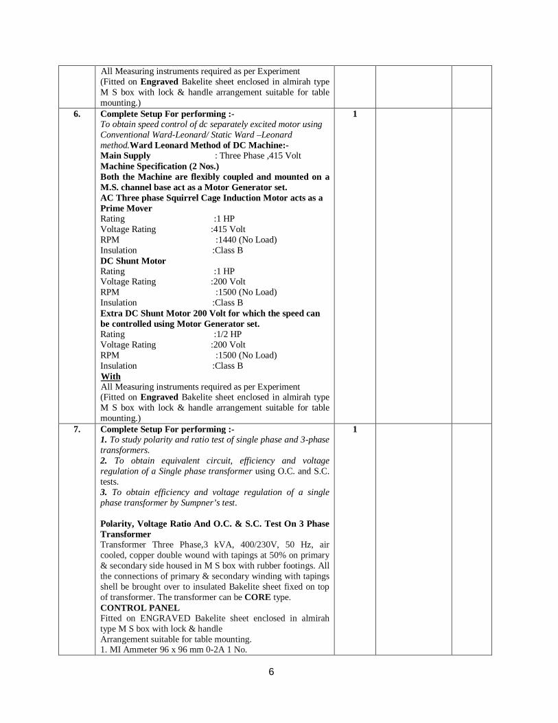
6. Complete Setup For performing :- To obtain speed control of dc separately excited motor using Conventional Ward-Leonard/ Static Ward –Leonard method.Ward Leonard Method of DC Machine:- Main Supply : Three Phase ,415 Volt Machine Specification (2 Nos.) Both the Machine are flexibly coupled and mounted on a M.S. channel base act as a Motor Generator set. AC Three phase Squirrel Cage Induction Motor acts as a Prime Mover Rating :1 HP Voltage Rating :415 Volt RPM :1440 (No Load) Insulation :Class B DC Shunt Motor Rating :1 HP Voltage Rating :200 Volt RPM :1500 (No Load) Insulation :Class B Extra DC Shunt Motor 200 Volt for which the speed can be controlled using Motor Generator set. Rating :1/2 HP Voltage Rating :200 Volt RPM :1500 (No Load) Insulation :Class B With All Measuring instruments required as per Experiment (Fitted on Engraved Bakelite sheet enclosed in almirah type M S box with lock & handle arrangement suitable for table mounting.)
1
7. Complete Setup For performing :- 1. To study polarity and ratio test of single phase and 3-phase transformers. 2. To obtain equivalent circuit, efficiency and voltage regulation of a Single phase transformer using O.C. and S.C. tests. 3. To obtain efficiency and voltage regulation of a single phase transformer by Sumpner’s test. Polarity, Voltage Ratio And O.C. & S.C. Test On 3 Phase Transformer Transformer Three Phase,3 kVA, 400/230V, 50 Hz, air cooled, copper double wound with tapings at 50% on primary & secondary side housed in M S box with rubber footings. All the connections of primary & secondary winding with tapings shell be brought over to insulated Bakelite sheet fixed on top of transformer. The transformer can be CORE type. CONTROL PANEL Fitted on ENGRAVED Bakelite sheet enclosed in almirah type M S box with lock & handle Arrangement suitable for table mounting. 1. MI Ammeter 96 x 96 mm 0-2A 1 No.
1

7
2. MI Ammeter 96 x 96 mm 0-10A 2 Nos. 3. MI Voltmeter 96 x 96 mm 0- 300 V 2 Nos. 4. MI Voltmeter 96 x 96 mm 0- 600 V 2 Nos. 5. Educational type Insulating Terminals 6. Indicating Light 7. TP MCB 8. LPF Wattmeter 2.5/5 Amp 150/300/600V 2 Nos. Additional Accessories 3 Phase Variac 0-470V 1 No. OPEN CIRCUIT AND SHORT CIRCUIT TESTS ON SINGLE PHASE TRANSFORMER MACHINE REQUIRED Single Phase Transformer 1 KVA, 230/230V with Tapings at 50% & 86.6% Naturally Air Cooled Copper Double wound, Shell type. The transformer will be housed in MS sheet box enclosure with rubber footings. All the terminals of primary & secondary shall be brought over to Bakelite sheet fitted on top of the box through insulated terminals. CONTROL PANEL FOR EXPERIMENT Fitted on Bakelite sheet enclosed in almirah type M S box with lock & handle arrangement suitable for table mounting. 1. MI Voltmeter 96 x 96 mm Sq 0-300V 1 No. 2. MI Voltmeter 96 x 96 mm Sq 0-30V 1 No. 3. MI Ammeter 96 x 96 mm Sq 0-10A 1 No. 4. MI Ammeter 96 x 96 mm Sq 0-1A 1 No. 5. Single Phase Single Element Dynamo type Wattmeter 1 No. 2.5/5 Amp, 75/150/300V Portable UPF type 6. Single Phase Single Element Dynamo type Wattmeter 1 No. 1/2 Amp, 75/150/300V Portable LPF type 7. Single Phase Variac Air Cooled 0-270V, 1No. TO OBTAIN EFFICIENCY & REGULATION OF A SINGLE PHASE TRANSFORMER BY SUMPNER’S (BACK TO BACK) TEST MACHINE REQUIRED FOR EXPERIMENT 2 Nos Single Phase Transformer 1 KVA, 230/230V with Tapings at 50% & 86.6% Naturally Air Cooled Copper Double wound, Shell type. The transformer will be housed in MS sheet box enclosure with rubber footings. All the terminals of primary & secondary shall be brought over to Bakelite sheet fitted on top of the box through insulated terminals. CONTROL PANEL FOR EXPERIMENT Fitted on Engraved Bakelite sheet enclosed in almirah type M S box with lock & handle arrangement Suitable for table mounting. 1. MI Voltmeter 96 x 96 mm 0-300V 1 No. 2. MI Voltmeter 96 x 96 mm 0-600V 1 No. 3. MI Voltmeter 96 x 96 mm 0-30V 1 No. 4. MI Ammeter 96 x 96 mm 0-5A2 No. 5. Single Phase Single Element Dynamo type 1 No. Wattmeter 2.5/5A, 75/150/300V 6. Single Phase Variac Air Cooled 0-270V, 1No.

8
8. Complete Setup For performing :- To obtain 3-phase to 2-phase conversion by Scott connection. TO STUDY THREE PHASE TO TWO PHASE CONVERSION OF 3 PHASE TRANSFORMER BY SCOTT CONNECTION MACHINE REQUIRED FOR EXPERIMENT 2 Nos Single Phase Transformer 1 KVA,230/230V with Tapings at 50% & 86.6% Naturally Air Cooled Copper Double wound, Shell type. The transformer will be housed in MS sheet box enclosure with rubber footings. All the terminals of primary & secondary shall be brought over to Bakelite sheet fitted on top of the box through insulated terminals. CONTROL PANEL FOR EXPERIMENT Fitted on Engraved Bakelite sheet enclosed in almirah type M S box with lock & handle arrangement suitable for table mounting. 1. MI Voltmeter 96 x 96 mm 0-300V 1 No. 2. MI Voltmeter 96 x 96 mm 0-600V 1 No. 3. MI Ammeter 96 x 96 mm 0-5A 5 No. 4. Three Phase Variac Air Cooled 0-270V, 1No 5. Electrical Load 5 KW, 230V with dual output 1 No. portable trolley mounted with castor wheels
1
Total
ELECTRICAL MEASUREMENT LAB
Sr. No.
NAME OF EQUIPMENT QTY. Rates in Rupees Cost in Rupees
• Complete Setup For performing :- Calibration of ac voltmeter and ac ammeter Apparatus required :- 1. Portable M.I. Voltmeter (for calibration) 0-250 V - 1 No. 2. Portable M.I. Voltmeter (Standard) 0-300 V - 1 No. 3. Single Phase Variac 0-6 A - 1 No. 4. M.I. Ammeter (for calibration) 0-2.5 A - 1 No. 5. Portable M.I. Ammeter (Standard) 0-10 A - 1 No. 6. Lamp Bank Load
02
• Complete Setup For performing :- Measurement of form factor of a rectified sine wave and determine source of error if r.m.s. value is measured by a multi-meter
02
• Complete Setup For performing :- Measurement of phase difference and frequency of a sinusoidal ac voltage using C.R.O.
02

9
• Complete Setup For performing :- Measurement of power and power factor of a single phase inductive load and to study effect of capacitance connected across the load on the power factor Apparatus required :- 1. M.I. Voltmeter 0-300 V - 1 No. 2. M.I. Ammeter 0-5 A - 2 Nos. 3. M.I. Ammeter 0-10 A - 1 No. 4. Single Phase Inductive Load (Choke Coil) 0-6A - 1 No 5. Single Phase Variac 0-8 A - 1 No. 6. Wire wound Rheostat 5 A, 45 Ohms - 1 No.
02
• Complete Setup For performing :- Measurement of low resistance by Kelvin’s double bridge
02
• Complete Setup For performing :- Measurement of voltage, current and resistance using dc potentiometer
02
• Complete Setup For performing :- Measurement of inductance by Maxwell’s bridge
02
• Complete Setup For performing :- Measurement of inductance by Hay’s bridge
02
• Complete Setup For performing :- Measurement of inductance by Anderson’s bridge
02
• Complete Setup For performing :- Measurement of capacitance by Owen’s bridge
02
• Complete Setup For performing :- Measurement of capacitance by De Sauty bridge
02
• Complete Setup For performing :- Measurement of capacitance by Schering bridge
02
• Complete Setup For performing :- Study of Frequency and differential time counter
02
• C.R.O. up to 30 Mhz 02 Total
ELECTROMECHANICAL ENERGY CONVERSION LAB – II
Sr. No. NAME OF EQUIPMENT QTY. Rates in Rupees Cost in Rupees
1. Complete Setup For performing :- 1. To perform no load and blocked rotor tests on a three phase squirrel cage induction motor and determine equivalent circuit. 2. To perform load test on a three phase induction motor and draw. 3. Torque -speed characteristics. 4. Power factor-line current characteristics. 5. To study speed control of three phase inductionmotor by Keeping V/f ratio constant Three Phase Induction Motor Trainer :- Main Supply :Three Phase 415 V ±10%,50Hz Motor´s Specification Type : Squirrel Cage Rating : 1HP
1

10
RPM :1440 (No Load) Tachometer :20,000 RPM With All Measuring instruments required as per Experiment (Fitted on Engraved Bakelite sheet enclosed in almirah type M S box with lock & handle arrangement suitable for table mounting.)
2. Complete Setup For performing: -To perform no load and blocked rotor tests on a single phase induction motor and determine equivalent circuit. Single Phase Induction Motor Trainer :- Induction Motor Type :Capacitor Phase : Single Current Type : AC Rating :1 HP Voltage rating : 230 V ±10%,50Hz MCB :10A Tachometer :20,000 RPM Mains Supply : 230 V ±10%,50Hz With All Measuring instruments required as per Experiment (Fitted on Engraved Bakelite sheet enclosed in almirah type ms box with lock & handle arrangement suitable for table mounting.)
1
3. Complete Setup For performing :- To study speed control of three phase induction motor by varying supply voltage Three Phase Variac(0-440 V ±10%,50Hz) With Voltmeter and Ammeter Motor´s Specification Type : 3-ΦSquirrel Cage Rating : 1HP RPM :1440 (No Load) Tachometer :20,000 RPM With All Measuring instruments required as per Experiment (Fitted on Engraved Bakelite sheet enclosed in almirah type M S box with lock & handle arrangement suitable for table mounting.)
1
4. Complete Setup For performing :- To perform open circuit and short circuit tests on a three phase alternator and determine voltage regulation at full load and at unity, 0.8 lagging and leading power factors by (i) EMF method (ii) MMF method. Three Phase Synchronous Generator Trainer :- Input Supply :200 V Fixed DC 0-200 V Variable DC Machine Specification (2 Nos.) Both the Machine are flexibly coupled and mounted on a M.S. channel base DC Machine acts as a Prime Mover Type : DC Shunt Rating : 2 HP
1
11
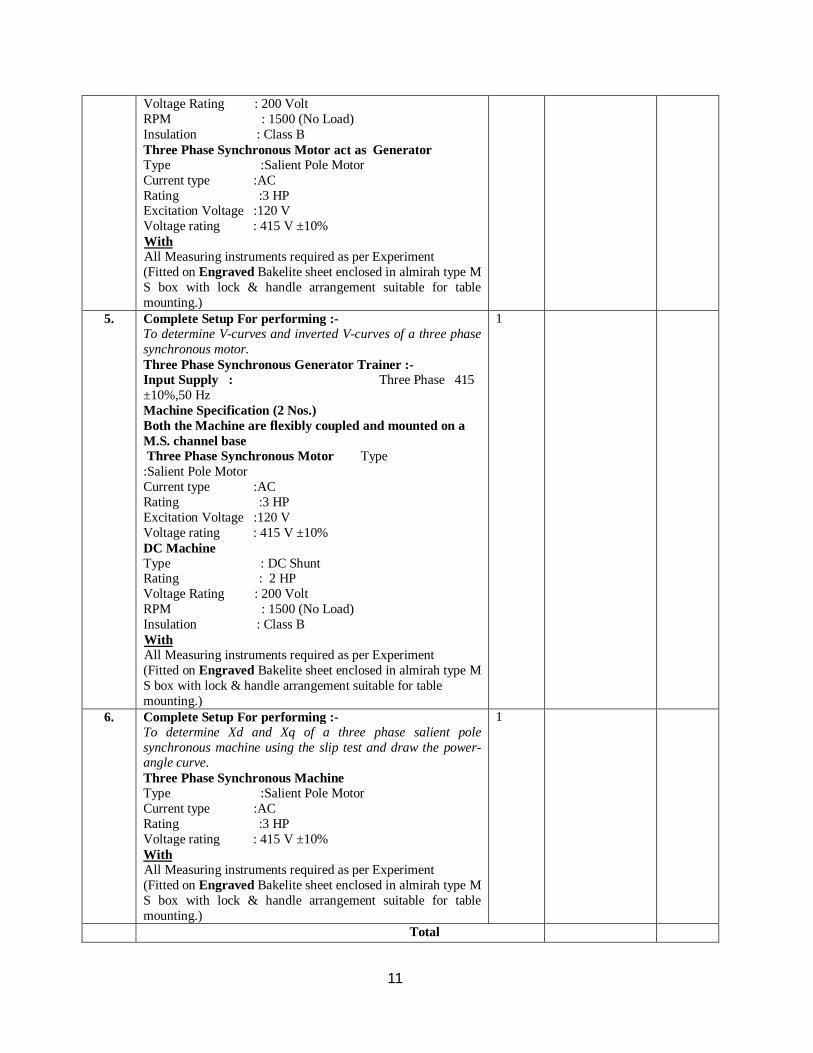
Voltage Rating : 200 Volt RPM : 1500 (No Load) Insulation : Class B Three Phase Synchronous Motor act as Generator Type :Salient Pole Motor Current type :AC Rating :3 HP Excitation Voltage :120 V Voltage rating : 415 V ±10% With All Measuring instruments required as per Experiment (Fitted on Engraved Bakelite sheet enclosed in almirah type M S box with lock & handle arrangement suitable for table mounting.)
5. Complete Setup For performing :- To determine V-curves and inverted V-curves of a three phase synchronous motor. Three Phase Synchronous Generator Trainer :- Input Supply : Three Phase 415 ±10%,50 Hz Machine Specification (2 Nos.) Both the Machine are flexibly coupled and mounted on a M.S. channel base Three Phase Synchronous Motor Type :Salient Pole Motor Current type :AC Rating :3 HP Excitation Voltage :120 V Voltage rating : 415 V ±10% DC Machine Type : DC Shunt Rating : 2 HP Voltage Rating : 200 Volt RPM : 1500 (No Load) Insulation : Class B With All Measuring instruments required as per Experiment (Fitted on Engraved Bakelite sheet enclosed in almirah type M S box with lock & handle arrangement suitable for table mounting.)
1
6. Complete Setup For performing :- To determine Xd and Xq of a three phase salient pole synchronous machine using the slip test and draw the power-angle curve. Three Phase Synchronous Machine Type :Salient Pole Motor Current type :AC Rating :3 HP Voltage rating : 415 V ±10% With All Measuring instruments required as per Experiment (Fitted on Engraved Bakelite sheet enclosed in almirah type M S box with lock & handle arrangement suitable for table mounting.)
1
Total

12
Network Lab
Sr. No.
NAME OF EQUIPMENT QTY. Rates in Rupees Cost in Rupees
1. Complete Setup For performing :- Verification of principle of superposition with dc and ac sources. 1. Experimental kit fitted with :- (a) Bread Board – 01 (b) Voltage Source – 02 (c) Current Source – 01 2. Instrument ModuleORMultimeters 3. Carbon Resistances :- (a) 1 KW – 05 (b) 2 KW – 05 (c) 5 KW – 05 (d) 10 KW – 05 4. Patch Cords
02
2. Complete Setup For performing :- Verification of Thevenin, Norton and Maximum power transfer theorems in ac circuits (i) Variable AC Voltage Source – 2 Nos. (ii) Variable AC Current Source – 1 No. (iii) Inductors – 2 Nos. (iv) Capacitors – 6 Nos. (v) Fixed Resistances – 8 Nos. (vi) Variable Resistance – 2 Nos. (vii) Digital Multimeters
02
3. Complete Setup For performing :- Verification of Tellegin’s theorem for two networks of the same topology
02
4. Complete Setup For performing :- Determination of transient response of current in RL and RC circuits with step voltage input (i) DC Voltage Source (ii) Resistances – 5 Nos. (iii) Capacitances – 3 Nos. (iv) Inductors – 2 Nos.
02
5. Complete Setup For performing :- Determination of transient response of current in RLC circuit with step voltage input for underdamp, critically damp and overdamp cases (i) DC Voltage Source (ii) Resistances – 5 Nos. (iii) Capacitances – 3 Nos. (iv) Inductors – 2 Nos.
02
6. Complete Setup For performing :- Determination of frequency response of current in RLC circuit with sinusoidal ac input (i) DC Voltage Source (ii) Resistances – 5 Nos. (iii) Capacitances – 3 Nos. (iv) Inductors – 2 Nos.
02

13
(v) AF Oscillator 1 KHz 7. Complete Setup For performing :-
Determination of z and h parameters (dc only) for a network and computation of Y and ABCD parameters
02
8. Complete Setup For performing :- Determination of driving point and transfer functions of a two port ladder network and verify with theoretical values
02
9. Complete Setup For performing :- Determination of image impedance and characteristic impedance of T and Π networks, using O.C. and S.C. tests Write Demo for the following (in MS-Power point)
02
10. Complete Setup For performing :- Verification of parameter properties in inter-connected two port networks: series, parallel and cascade also study loading effect in cascade.
02
11. Complete Setup For performing :- Determination of frequency response of a Twin – T notch filter. (i) AF Signal Generator 1 KHz (ii) Resistances - 10 Nos (iii) Capacitances – 10 Nos.
02
12. Complete Setup For performing :- To determine attenuation characteristics of a low pass / high pass active filters.
02
Total

14
Electrical Instrumentation Lab
Sr. No.
NAME OF EQUIPMENT (Experiment Setup/Kit)
QTY. Rates in Rupees
Cost in Rupees
1. Complete Setup For performing :- Measurement of displacement using LVDT.
02
2. Complete Setup For performing :- Measurement of displacement using strain gauge based displacement transducer.
02
3. Complete Setup For performing :- Measurement of displacement using magnetic pickup.
02
4. Complete Setup For performing :- Measurement of load using strain gauge based load cell.
02
5. Complete Setup For performing :- Measurement of water level using strain gauge based water level transducer
02
6. Complete Setup For performing :- Measurement of flow rate by anemometer
02
7. Complete Setup For performing :- Measurement of temperature by RTD.
02
8. Complete Setup For performing :- Measurement of temperature by thermocouple
02
9. Complete Setup For performing :- Study of P,PI and PID controllers
02
10. Complete Setup For performing :- Study of storage oscilloscope and determination of transient response of RLC circuit.
02
11. Complete Setup For performing :- Determination of characteristics of a solid state sensor/fiber-optic sensor
02
12. Complete Setup For performing :- Design and test a signal conditioning circuit for any transducer
02
Total

15
Power Electronics Lab
Sr. No.
NAME OF EQUIPMENT QTY. Rates in Rupees
Cost in Rupees
1. Complete Setup For performing :- To study V-I characteristics of SCR and measure latching and holding currents.Complete setup with digital measuring instruments. · Demonstration board with following facilities :- (a) Isolated 0-230 V DC variable source – 1 Set (b) Isolated 0-600 V DC variable source – 1 Set (c) Isolated 0-12 V DC variable source – 2 Sets (d) External Load – 3 Nos. (e) SCR · Multimeter · Lamp 15 Watt 230 V – 2 Nos. · Patch Cords. · Demonstration Board Cover. · To conduct SCR Shorted gate experiment · To conduct biased (Forward & Reverse) gate SCR firing experiments · Set of Patch Chords & Manual.
02
2. Complete Setup For performing :- To study UJT trigger circuit for half wave and full wave control. Setup will consists of :- · Demonstration Board with following facilities :- (a) Isolated AC 230 V & 14 V Supply (b) 10:1 Resistive Attenuator for observation on CRO. (c) Fuse for short circuit protection. · 25 Watt 250 V Lamp. · Demonstration Board Cover · Triggering circuits · Set of Patch Chords & Manual
02
3. Complete Setup For performing :- To study single-phase half wave controlled rectified with (i) resistive load (ii) inductive load with and without freewheeling diode. The setup is provided with isolation transformer for C.R.O. protections and lamp bank. 1. Demonstration Board with following facilities :- (a) Single Phase Half Controlled Bridge (b) Firing Pulse Generator (c) Resistive Load (Lamp) (d) Inductive Load (Choke) (e) Voltmeter 0-300V (f) Ammeter 0-5A (g) 1:10 Attenuator for CRO (h) Isolated 220 V AC for CRO 2. DC Motor 1 HP 3. Connecting Leads 4. Lamp Holder
01

16
5. Lamp 250 Volts Complete experimental setup with DC Motor & Engraved Panel board with Banana Sockets for ease of connections by students
4. Complete Setup For performing :- To study single phase (i) fully controlled (ii) half controlled bridge rectifiers with resistive and Inductive loads. Features :- · 230V, AC Isolated Transformer, Power 50 Watt · 9V DC at 100 mA Zener Regulated Power Supply · Two UJT. · Two Pulse Transformer1:1:1. · Two Potentiometers for controlling UJT firing angle. · Bulb 40W, 230 AC · Adequate no of others Electronics Components.
02
5. Complete Setup For performing :- To study three-phase fully/half controlled bridge rectifier with resistive and inductive loads. Features :- · Three Phase line commuted fully-controlled thyristorized bridge converter. · Miniature Circuit Breaker (MCB). · Three cards consisting of Zero Crossing Detector, Integrator, Comparator and Pulse Generator one for each phase, for controlling thyristors. Another card in conjunction with above three cards for controlling the triggering angles of the negative group of three thyristors. · Firing angle control potentiometer. · 415:50V transformer for rectification and low voltage AC supply for triggering. · 12V at 500mA, power supply for triggering circuit. · Six nos. Driver Circuits with Pulse Transformer. · R & L load with Load voltage divider. · Panel meter for measurement of voltage & current. · One freewheel diode. · Unearthed mains sockets for CRO.
01
6. Complete Setup For performing :- To study single-phase ac voltage regulator with resistive and inductive loads. Complete setup with fraction Horse Power Motor. · AC Phase Control training unit with following facilities :- (a) Isolated 230 V or 50 V supply (b) Fuse for Short Circuit protection (c) AC Phase control by RC Triggering (d) AC Phase Control by UJT Triggering (e) 10:1 Potential Divider for CRO · Protection Cover - 1 No. · Lamp 25 Watt, 230 V - 1 No. · Set of Patch Chords & Manual. Complete setup with Motor
02

17
7. Complete Setup For performing :- To study single phase cyclo-converter The experimental setup consists of :- (i) Power Circuit consisting of two fully controlled Bridge Converter connected in anti Parallel (Bridges P & N). Bridge P supplies load current in the positive half of output cycle and bridge N provides load current in the negative half of output cycle. (ii) Firing Circuit consists of Micro Controller Based Firing Unit which provides Isolated Gate pulses through pulse transformers separately for P & N Bridges. Toggle switch is provided to select the output frequency (1/1f, 1/2f, 1/3f, 1/4f, 1/5f). Firing angle can be changed either :- a) through toggle switches for increasing and decreasing of firing angle. Firing angle during all half cycles of AC input supply remains same in this mode of control. b) through serial port of computer by connector provided on the experimental kit to the serial port of computer and than entering the firing angle to the key board. In this mode of control the firing angle of each half cycle of input supply can be independently controlled. (iii) Patch Cord. (iv) Instruction Manual
01
8. Complete Setup For performing :- To study triggering of (i) IGBT (ii) MOSFET (iii) power transistor 1. Complete experimental setup consisting demonstration Board with following facilities :- (a) 110 V DC Supply (b) Different testing points (c) 1:10 Attenuator for CRO (d) Triggering Generator (e) IGBT, Mosfet& Power Transistor 2. Lamp 15 Watt 250V 3. Connecting Leads
02
9. Complete Setup For performing :- To study operation of IGBT/MOSFET chopper circuit This is DC chopper circuit for getting a variable DC voltage by using on time control and frequency control to feed DC (Universal Motor). Circuit demonstrate the use of smooth speed variation with the help of chopper circuit and test points are provided.
01
18
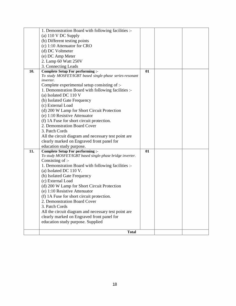
1. Demonstration Board with following facilities :- (a) 110 V DC Supply (b) Different testing points (c) 1:10 Attenuator for CRO (d) DC Voltmeter (e) DC Amp Meter 2. Lamp 60 Watt 250V 3. Connecting Leads
10. Complete Setup For performing :- To study MOSFET/IGBT based single-phase series-resonant inverter. Complete experimental setup consisting of :- 1. Demonstration Board with following facilities :- (a) Isolated DC 110 V (b) Isolated Gate Frequency (c) External Load (d) 200 W Lamp for Short Circuit Protection (e) 1:10 Resistive Attenuator (f) 1A Fuse for short circuit protection. 2. Demonstration Board Cover 3. Patch Cords All the circuit diagram and necessary test point are clearly marked on Engraved front panel for education study purpose.
01
11. Complete Setup For performing :- To study MOSFET/IGBT based single-phase bridge inverter. Consisting of :- 1. Demonstration Board with following facilities :- (a) Isolated DC 110 V. (b) Isolated Gate Frequency (c) External Load (d) 200 W Lamp for Short Circuit Protection (e) 1:10 Resistive Attenuator (f) 1A Fuse for short circuit protection. 2. Demonstration Board Cover 3. Patch Cords All the circuit diagram and necessary test point are clearly marked on Engraved front panel for education study purpose. Supplied
01
Total

19
POWER SYSTEM LAB
S NO. NAME OF EQUIPMENT QTY. Rates in Rupees
Cost in Rupees
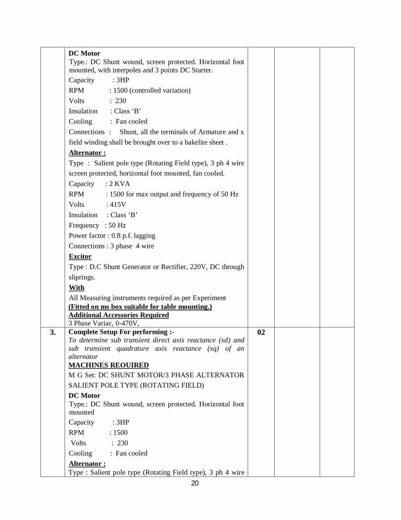
1. Complete Setup For performing :- To determine negative and zero sequence reactance of an alternator. MACHINES REOUIRED M G Set: DC SHUNT MOTOR/3 PHASE ALTERNATOR SALIENT POLE TYPE (ROTATING FIELD) DC Motor Type.: DC Shunt wound, screen protected. Horizontal foot mounted, with interpoles and 3 points DC Starter Capacity: 3HP RPM : 1500 (controlled variation) Volts : 230 Insulation : Class ‘B’ Cooling : Fan cooled Connections : Shunt, all the terminals of Armature and x field winding shall be brought over to a bakelite sheet . Alternator : Type : Salient pole type (Rotating Field type), 3 ph 4 wire screen protected, horizontal foot mounted, fan cooled, separately excited Capacity : 2 KVA RPM : 1500 for max output and frequency of 50 Hz Volts : 415V Insulation : Class ‘B’ Frequency : 50 Hz Power factor : 0.8 p.f. lagging Exciter Type : Static type through Rectifier With All Measuring instruments required as per Experiment (Fitted on ms box suitable for table mounting.)
02
2. Complete Setup For performing :- To determine direct axis reactance (xd) and quadrature axis reactance (xq) of a salient pole alternator. MACHINES REOUIRED M G Set: DC SHUNT MOTOR/3 PHASE ALTERNATOR SALIENT POLE TYPE (ROTATING FIELD)
02
20
DC Motor Type.: DC Shunt wound, screen protected. Horizontal foot mounted, with interpoles and 3 points DC Starter. Capacity : 3HP RPM : 1500 (controlled variation) Volts : 230 Insulation : Class ‘B’ Cooling : Fan cooled Connections : Shunt, all the terminals of Armature and x field winding shall be brought over to a bakelite sheet . Alternator : Type : Salient pole type (Rotating Field type), 3 ph 4 wire screen protected, horizontal foot mounted, fan cooled. Capacity : 2 KVA RPM : 1500 for max output and frequency of 50 Hz Volts : 415V Insulation : Class ‘B’ Frequency : 50 Hz Power factor : 0.8 p.f. lagging Connections : 3 phase 4 wire Excitor Type : D.C Shunt Generator or Rectifier, 220V, DC through sliprings. With All Measuring instruments required as per Experiment (Fitted on ms box suitable for table mounting.) Additional Accessories Required 3 Phase Variac, 0-470V,
3. Complete Setup For performing :- To determine sub transient direct axis reactance (xd) and sub transient quadrature axis reactance (xq) of an alternator MACHINES REOUIRED M G Set: DC SHUNT MOTOR/3 PHASE ALTERNATOR SALIENT POLE TYPE (ROTATING FIELD) DC Motor Type.: DC Shunt wound, screen protected. Horizontal foot mounted Capacity : 3HP RPM : 1500 Volts : 230 Cooling : Fan cooled Alternator : Type : Salient pole type (Rotating Field type), 3 ph 4 wire
02

21
screen protected, horizontal foot mounted Capacity : 2 KVA RPM : 1500 for max output and frequency of 50 Hz Volts : 415V Insulation : Class ‘B’ Frequency : 50 Hz Excitor Type : D.C Shunt Generator or Rectifier, 220V With All Measuring instruments required as per Experiment (Fitted on ms box suitable for table mounting.)
4. Complete Setup For performing :- To determine fault current for L-G, L-L, L-L-G and L-L-L faults at the terminals of an alternator at very low excitation MACHINES REQUIRED : M G Set : D C SHUNT MOTOR/3 PHASE ALTERNATOR SALIENT POLE TYPE (ROTATING FIELD) DC Motor Type.: DC Shunt wound, screen protected. Horizontal foot mounted Capacity : 3HP RPM : 1500 Volts : 230 Cooling : Fan cooled Alternator : Type : Salient pole type (Rotating Field type), 3 ph 4 wire screen protected, horizontal foot mounted Capacity : 2 KVA RPM : 1500 for max output and frequency of 50 Hz Volts : 415V Frequency : 50 Hz Connections : 3 phase 4 wire Excitor Type : Static type through Rectifier With All Measuring instruments required as per Experiment (Fitted on ms box suitable for table mounting.)
02
5. Complete Setup For performing :- To study the IDMT over current relay and determine the time current characteristics APPARATUS REQUIRED IDMT over current relay With All Measuring instruments required as per Experiment
02

22
(Fitted on ms box suitable for table mounting.) 6. Complete Setup For performing :-
To study percentage differential relay APPARATUS REQUIRED All Measuring instruments required as per Experiment (Fitted on ms box suitable for table mounting.)
02
7. Complete Setup For performing :- To determine location of fault in a cable using cable fault locator APPARATUS REQUIRED CABLE FAULT LOCATOR Complete experimental setup consisting of Rheostat, Galvanometer, Measuring Tape, 3 Core Cable, DC Power Source, Digital Measuring Instrument
02
8. Complete Setup For performing :- To study ferranty effect and voltage distribution in H.V. long transmission line using transmission line model. APPARATUS REQUIRED Complete Experimental satup as per requirement of the Experiment, fitted in m.s. sheet box complete with patch cords for inter connection & Manual.
02
9. Complete Setup For performing :- To study operation of oil testing set. APPARATUS REQUIRED Complete Experimental satup as per requirement of the Experiment,with testing kit and sample of oil.
02
10. Complete Setup For performing :- To study Impedance, MHO and Reactance type distance relays APPARATUS REQUIRED Complete Experimental setup as per requirement of the Experiment, fitted in m.s. sheet box complete with patch cords for inter connection & Manual.
02
Total

23
Electric Drives Lab
Sr. No.
NAME OF EQUIPMENT QTY. Rates in Rupees
Cost in Rupees
1. Complete Setup For performing :- To study speed control of separately excited dc motor by varying armature voltage using single-phase fully controlled bridge converter. 1. Engraved Demonstration Board with following facilities :- (a) Single Phase Fully Controlled Bridge (b) Firing Pulse Generator Digital type (c) Resistive Load (Lamp) With & without free wheeling Diode (d) Inductive Load (Choke) (e) Voltmeter 0-300V (f) Ammeter 0-5A (g) 1:10 Attenuator for CRO (h) Isolated 220 V AC for CRO 2. DC Motor 1 HP 3. Connecting Leads 4. Lamp Holder 5. Lamp 250 Volts Complete experimental setup with DC Motor Engraved Panel board with Banana Sockets forease of connections by students
01
2. Complete Setup For performing :- To study speed control of separately excited dc motor by varying armature voltage using single phase half controlled bridge converter. Demonstration Board with following facilities :- (a) Single Phase Half Controlled Bridge (b) Firing Pulse Generator (c) Resistive Load (Lamp) (d) Inductive Load (Choke) (e) Voltmeter 0-300V (f) Ammeter 0-5A (g) 1:10 Attenuator for CRO (h) Isolated 220 V AC for CRO 2. DC Motor 1 HP 3. Connecting Leads 4. Lamp Holder 5. Lamp 250 Volts
01
3. Complete Setup For performing :- To study speed control of separately excited dc motor using single phase dual converter (Static Ward-Leonard Control) (i) Power Circuit consisting of two single phase fully controlled Bridge Converter connected in anti parallel. (ii) Centre Tap Inductor required for circulating mode operation of dual converter. (iii) Micro controlled based firing circuit which generates firing pulses for both P and N converters. (iv) MCB, Voltmeter, Ammeter and Lamp load (v) Patch Cord & Instruction Manual (vi) DC Motor 1 HP, 230V
01

24
4. Complete Setup For performing :- To study speed control of separately excited dc motor using MOSFET/IGBT chopper 1. Demonstration Board with following facilities :- (a) 110 V DC Supply (b) Different testing points (c) 1:10 Attenuator for CRO (d) DC Voltmeter (e) DC Amp Meter 2. Lamp 60 Watt 250V 3. Connecting Leads
01
5. Complete Setup For performing :- To study closed loop control of separately excited dc motor
01
6. Complete Setup For performing :- To study speed control of single phase induction motor using single phase ac voltage controller The experimental setup consisting of :- (i) Micro Controller Kit with firing circuit. (ii) Single Phase Induction Motor Capacitor Run with Loading arrangement (iii) Patch Cord. (iv) Instruction Manual With AC Motor 0.5 HP , FHP Single Phase with loading arrangement
01
7. Complete Setup For performing :- To study speed control of three phase induction motor using three phase ac voltage controller 3 phase, 415 volt 1.0 HP squirrel cage induction motor drive by Micro Control Based firing angle alongwith motor-generating set. Consisting of AC Induction Motor 1 HP 415 V, 1440 RPM coupled to DC Shunt Generator 230V with lamp bank load. DESCRIPTION 1. This unit consists of two parts :- (a) Power Circuit :- It consist of 6 Thyristors connected in anti-parallel (2SCRs in each phase). By controlling the firing angle of the thyristors connected in anti-parallel in each phase, the rms value of the stator voltage can be regulated. As a consequence, motor torque and thus speed of the drive is controlled. (b) Control Circuit :- FCR-100 (8051) microcontroller based SCR Bridge controller is used for controlling the firing circuit. 2. Soft push buttons provided for increasing or decreasing the firing angle. 3. 3-phase MCB 4. LCD display of the firing angle. 5. 10:1 Attenuator with Isolation Transformer for observation of wave form on CRO. With AC Induction Motor 1 HP 415 V, 1440 RPM coupled to DC Shunt Generator 230V with lamp bank load.
01
8. Complete Setup For performing :- To study speed control of three phase induction motor using three phase current source inverter
01
9. Complete Setup For performing :- 01

25
To study speed control of three phase induction motor using three phase voltage source inverter
10. Complete Setup For performing :- To study speed control of three phase slip ring induction motor using static rotor resistance control using rectifier and chopper (a) Power Circuit : This part consists of a 3-phase bridge rectifier to convert 3-phase rotor supply to DC supply. An indicator is connected in series with the DC supply for smoothning of a DC. A Glass fuse is connected in series with the DC supply. An IGBT is provided for chopper control MOSFET is mounted on a proper heat sink. Snubber circuit is connected across MOSFET for dv/dt. A fuse is also provided for protection. All the points are brought out on the front panel for interconnection. (b) Control Circuit :The control circuit generates driver output for driving the MOSFET in chopper mode. The duty cycle can be varied from 0% to 90%. The frequency can be varied. Soft start and soft stop is provided for driver output
01
11. Complete Setup For performing :- To study speed control of three phase slip ring induction motor using static scherbius slip power recovery control scheme 1 HP Induction Motor Slipring Type for demonstration of speed variation of induction motor. Ammeter/Voltmeter provided alongwith the set up. Electronic Controller includes Power Supply, Firing, Circuit, Contactor, SCR Bridge Inverter and 6 diode bridge converter for rotor side. DV/DT protection for Thyristors included.
01
Total
Signature & Seal of Tenderer

26
Submission of the Tender:
1. Sealed tenders in along with earnest money amounting to the value mentioned with each item in the tender document in form of demand draft only. The tenders should reach to undersigned latest by 28 March up to 2: OO P. M.
2. Tenders should be submitted either in person or by post in sealed envelopes on which the name of department, item quoted; tender number and date along with name and address of the firm will be written.
3. Tender cost (non refundable) (ii) Earnest Money (iii) Proof of PAN and TIN registration document (iv) Standing of the firm (v) Major supplies executed in recent past (vi) Authorized dealer certificate from OEM & Commercial terms and conditions. The rates must be quoted in both figures and words. Any overwriting and/or cutting must be duly attested failing which tenders are likely to be rejected.
4. Tender Cost and Earnest money amounting to the value given in the tender document for each Lab should also be submitted with the tender in the form of separate Demand Drafts drawn in favour of Director, BIET, Jhansi.
5. Earnest money and Cost of Tender in the form of Bank Drafts must be placed in a separate sealed envelope by writing “Earnest Money” on top of the envelope.
6. All the envelopes as above must be kept and sealed in a big envelop. The name of items quoted, enquiry/tender no and the opening date should invariably be mentioned on the top of big envelope.
7. Sealed tenders should be sent to Director, Bundelkhand Institute of Engineering and Technology (BIET) Campus, Kanpur Road, Jhansi -284128 latest by 28 March at 2: 00 P.M. . The sealed tenders may be dropped in the box kept at Store and Purchase section at BIET, Jhansi.
Terms and Conditions for Submission of Tenders
1. Firms will have to attach the list of customers to whom they have supplied similar items in previous year along with performance reports. Total turnover of the firm must be atleast 50 Lacs per year in the last three years consecutive years. A certificate to these effects should be issued from the sales tax department.
2. The descriptive and illustrative literature of the quoted item in original must accompany with the tender.
3. Tenders received after the closing date and stipulated time shall not be considered and the institute shall not be responsible for any postal delay.
4. Tender should be valid atleast for a period of 04 months. (04 Months from opening date of tender). 5. Our terms of payments are strictly after receipt of material and check at our institute regarding
the quality and working experience. 6. The rates should be quoted FOR store, Bundelkhand Institute of Engineering and Technology
(BIET) Campus, Kanpur Road, Jhansi -284128. Inclusive of all taxes/excise duty/fright/package/forwarding expenses/insurance etc.
7. Firm shall be solely responsible for defective supplies and losses caused to institute on account of defective supply.
8. Tenders brought personally should be dropped into tender box. 9. Suppliers must be registered with sales tax department and they should state registration no.
10. Quantity of items may increase or decrease or may be cancelled upto any extent. 11. No sales tax form “C” or “D” etc for concessional rate shall be provided by the institute.

27
12. All tender must be accompanied by EMD as mentioned in the tender document in the form of Demand Draft drawn in favour of Director, Bundelkhand Institute of Engineering and Technology (BIET) Jhansi.
13. Tenders deviating from above terms and conditions shall be rejected straight way without assigning any reason thereof.
14. EMD will be forfeited if the equipment’s are not supplied in given time. 15. If required, the firms have to supply the sample of the items. 16. If certain equipment/material needs to be checked/tested at site of the firm, all expenditure
(including TA/DA) of our expert members shall be borne by the firm concerned. 17. Penalty : The firm, which is not able to supply the equipment’s/materials mentioned in purchase
order by the due date , shall be liable to pay a penalty equal to 0.10 % of the value of purchase order per day. However this can be waived of by the Director under special circumstances.
18. Payment: - Ninety percent of contract price shall be paid to the supplier after the delivery / commissioning / testing and completion of the work. The remaining 10% of contract price shall be paid to the supplier within 30 days after satisfactory working.
19. Director has every right to extend the due date if so required but all the tenders will be opened together.
20. Deduction of TDS (Income Tax & VAT) as per Govt. Rules.
21. The firm must provide original Guarantee/Warrantee card as issued by the manufacturer, as the case may be.
22. The Director BIET, Jhansi may reject any or all quotations/tenders without assigning any
reasons.
23. All disputes subject to Jhansi Jurisdiction only.
For BIET, Jhansi


![arXiv:1602.09073v3 [cond-mat.mes-hall] 23 Mar 2016. of Physics, Bundelkhand University, Jhansi, 284128, India 3Dept. of Physics, Indian Institute of Technology Kanpur, Kanpur 208016,](https://static.fdocuments.us/doc/165x107/5aa92a057f8b9a7c188c7380/arxiv160209073v3-cond-matmes-hall-23-mar-2016-of-physics-bundelkhand-university.jpg)