Bully Dog Performance Chips Installation Instructions - CARiD · John Deere 8130 to 8530 40605: ......
14
INSTALLATION MANUAL Applications Rapid Power Part # John Deere 8130 to 8530 40605 John Deere 8230T to 8430T 40605 John Deere 8120 to 8520 40605 John Deere 8120T to 8520T 40605 John Deere 8030 and 8020 Series Module
Transcript of Bully Dog Performance Chips Installation Instructions - CARiD · John Deere 8130 to 8530 40605: ......

inSTAllATiOn mAnuAl
Applications Rapid Power Part #
John Deere 8130 to 8530 40605John Deere 8230T to 8430T 40605John Deere 8120 to 8520 40605John Deere 8120T to 8520T 40605
John Deere 8030 and 8020 Series Module

Product description:The product is made up of two different parts, the module box, and cable.
ThE MODUlE bOx: The module box contains the electron-ics that will allow your tractor to produce more horsepower. It is very important that this module is mounted away from all moving or hot parts. The box should be placed in an area protected from dirt and moisture.
ThE CablE: This cable allows the Rapid Power Module to connect to your tractors engine. At the end of the wiring harness are four plugs, two male and two female plugs. These plugs will connect directly to the tractors engine and wiring harness requiring no modification of the tractor.
inTrOduCTiOn
Male Plug
Male Plug
Female Plug Female Plug
Contents:1. Rapid Power Module
with Wiring Harness2. Zip Ties
ThE MODUlE bOx
FUEl RaIl pRESSURE SENSOR plUgS
Map SENSOR plUgS

8030 SerieS Product Placement overview:
rPm deSCriPTiOn
Air
Filte
rM
AP
Sens
orFu
el R
ail P
ress
ure
Sens
or

inStallation inStructionS:
1. Open Hood of Tractor, install module when engine is not running and cool.
2.: Place module below the air filter in a safe location and run cable along the wiring harness toward the top of the engine.
3. Remove plug from the MAP sensor located at the top of the engine.
rPm inSTAllATiOn
MAP Sensor
Note: Make sure the gray cap is securely fas-tened to male plug and is not in the MAP Sensor.

4. Plug tractor male plug into module female plug
5. Plug the module male plug into the tractor MAP sensor.
6. Continue routing module cable along the wiring harness above the engine. Run the cable down be-tween the engine block and starting fluid can to the location shown.
7.:Disconnect the plug from the factory fuel rail pres-sure sensor.
Fuel Rail Pressure Sensor
Module Female Plug
Module cable run
Module Male Plug
rPm inSTAllATiOn
Warning: There might be a tamper resistant sleeve that needs to be removed from the Fuel rail pressure sensor. If applicable, remove carefully as to not void the tractor’s warranty.

8. Insert module female plug into fuel rail pressure sensor.
9. Connect the module male plug to the tractor female plug.
10. Use zip ties to secure the Rapid Power cable to the tractor wiring harness. Be sure the cable will be safe from moving parts (such as the starter/flywheel) or hot exhaust system parts. Zip tie the module box to the cable harness as shown.
Fuel Rail Sensor Female Plug
Module Male Plug
Module Female Plug
Fuel Rail Sensor Plug
rPm inSTAllATiOn
Warning: Do not remove module while tractor is
running. Shut down machine and then remove module.
rPm inSTAllATiOn
The Rapid Power module will increased power and capability for your 8020 series tractor. Without changing the wiring harness the Rapid Power Module can be modified to work with the 8020 series tractor. The Module will provide you the power and reliability that you have come to expect from Bully Dog Technologies.
1.: Open Hood of Tractor, install module when engine is not running and is cool.
2.: Place module below the air filter in a safe location and run cable along the wiring harness toward the front of the engine.
3.:Locate the Fuel Rail pressure sensor.
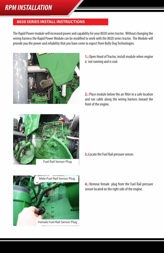
4.: Remove female plug from the Fuel Rail pressure sensor located on the right side of the engine.
8020 SerieS inStall inStructionS
Fuel Rail Sensor Plug
Male Fuel Rail Sensor Plug
Female Fuel Rail Sensor Plug

rPm inSTAllATiOn
5.: Route the Rapid Power fuel pressure sensor cable to the fuel rail pressure sensor.
6.: Insert the Rapid Power module female fuel pres-sure sensor plug to the male fuel pressure sensor.
7.: Insert the Rapid Power module male fuel pressure sensor plug to the female fuel pressure sensor.

rPm inSTAllATiOn
8020 SerieS inStall inStructionS8.: Locate the Rapid Power Module MAP sensor plugs.
9.: Couple the Female and Male ends of the Rapid Power Module MAP sensor plugs. Use of these plugs is not needed on the 8020 Series tractors.
10.: Attach the MAP sensor plugs to the main cable us-ing a zip tie that will secure the plugs for future use.

rPm inSTAllATiOn
11.: Zip Tie module and loop and zip tie any remaining cable. Ensure that the cable and module will be safe from moving parts (such as the starter/flywheel) or hot exhaust system parts.
Tractors Stock Low Power Level Total Horsepower
High Power Level Total Horsepower*
JD 8130* 180 HP ~200 ~215
JD 8230* 200 HP ~220 ~240
JD 8330* 225 HP ~250 ~270
JD 8430* 250 HP ~275 ~300
JD 8530* 275 HP ~300 ~330
JD 8230 T* 200 HP ~220 ~240
JD 8330 T* 235 HP ~260 ~280
JD 8430 T* 255 HP ~280 ~305
JD 8120 (T) 170 HP ~200 ~220
JD 8220 (T) 190 HP ~220 ~250
JD 8320 (T) 215 HP ~250 ~280
JD 8420 (T) 235 HP ~270 ~305
JD 8520 (T) 255 HP ~290 ~330
This chart illustrates the approximate power increase when the Rapid Power Module is set at the desired power level.~ Denotes an approximate value.
*Due to John Deere’s new software updates, the ‘High’ power level should not beused for the 08’ John Deere 8030 series tractors or any 8030 tractor that has been re-flashed by a John Deere dealer. Use of the ‘High’ power setting with these tractors will result in warning lights and codes. If warning codes appear while operating, shut the tractor down, adjust the module to the ‘Low’ power level, and continue operation. If problems persists contact Bully Dog Tech Support at 1-866-285-5936.
Warning: Do not remove module while tractor is
running. Shut down machine and then remove module.

OPerATing inSTruCTiOnS
oPerating inStructionS:
INTERNal pOwER lEvEl SwITCh: The Rapid Power module has three power settings, Stock, Low Power Level or High Power Level. To select different power levels remove the cover of the module box, locate the red internal power switch, and set the switch to the desired power level per illustrations below.
Be sure to securely fasten the module cover after changing the power level. Make sure the cable exits the box properly in the hole provided.
1. After completing the installation of the module, turn the tractor on to test if the module is working. If the tractor starts then the module is working. If the tractor does not start, check all of the connections on the install to be sure that they are secure and then attempt to start the tractor again.
2. Adjust performance setting to desired level and enjoy.
warranty
ON
1 2
Both switches in the “off” position indicates Stock performance
First switch in the “on” position
indicates Low Power Level.
Second switch in the “on” Position
indicates High Power Level.
Both switches in the “on” Position
indicates High Power Level.
USB Port
Internal Power Switches
ON
1 2
ON
1 2
ON
1 2
Stock Low Power Level
External Power Switch Female Plug (External Switch part number 40610)
High Power LevelThese two positions provide the same power.
*Due to John Deere’s new software updates, the ‘High’ power level should not be used for the 08’ John Deere 8030 series tractors or any 8030 tractor that has been re-flashed by a John Deere dealer. Use of the ‘High’ power setting with these tractors will result in warning lights and codes. If warning codes appear while operating, shut the tractor down, adjust the module to the ‘Low’ power level, and continue operation. If problems persists contact Bully Dog Tech Support at 1-866-285-5936.

OPerATing inSTruCTiOnS
INTERNET UpgRaDES/UpDaTE agENTIMPORTANT: The information on this page is applicable to all vehicles and tractors.
The most efficient way of keeping up to date with Bully Dog product versions is to use the Update Agent©. The Update Agent is a software program developed by Bully Dog Technologies specifically to update Bully Dog products. The Update Agent is easy to use, it can be loaded on any windows based PC running Windows 2003 or newer. The Update Agent is attainable free of charge at the Bully Dog download center or by ordering a CD ROM through a Bully Dog distributor.

Your computer will not recognize the Module until the Driver is installed.
1) Remove cover from Rapid Power Module2) Plug Module into PC using a USB cable (Male A end for PC, Male B end for Module: Same type ofcable as used for most printers)3) Windows will recognize the Module and attempt to install software.4) If Windows asks if it can connect to Windows Update to search for the software select NO, not atthis time. Select Next to continue.
5) Select Install Automatically, then press next.
6) Windows will ask you to select the software you would like to install. Select BDT Rapid PowerUSB and select next.
inTerneT uPdATe
USB Driver Installation (Windows XP only!)
IMPORTANT: Install the Update Agent prior to plugging in your module .

inTerneT uPdATe
7) Windows will warn that this driver is not signed, but select continue anyway!
8) Allow the driver installation to complete and click FINISH
9) The Update Agent should now recognize the device and allow the update to take place. Thiscould take approximately 30 Seconds or more