Hugo Sax, MD Division of Infectious Diseases and Hospital ...

SHOULDER ARTHROPLASTY: STATE OF THE ARTProceedings of the Exactech Master’s Course in Shoulder ArthroplastySan Francisco, California, August 6–7, 2015Guest EditorsDavid Collins, M.D.Lynn Crosby, M.D. Richard Friedman, M.D., F.R.C.S.C.
BASIC SCIENCE
S5 ReverseShoulderArthroplastyProsthesisDesignClassificationSystem Howard D. Routman, D.O., Pierre-Henri Flurin, M.D., Thomas W.
Wright, M.D., Joseph D. Zuckerman, M.D., Matthew A. Hamilton, Ph.D., and Christopher P. Roche, M.S., M.B.A.
S15 TheImpactofPosteriorWearonReverseShoulderGlenoidFixation Richard Friedman, M.D., F.R.C.S.C., Nicholas Stroud, M.S., Kaycee
Glattke, B.S., Pierre-Henri Flurin, M.D., Thomas W. Wright, M.D., Joseph D. Zuckerman, M.D., and Christopher P. Roche, M.S., M.B.A.
S21 RoleofSubscapularisRepaironMuscleForceRequirementswithReverse Shoulder Arthroplasty
Matthew L. Hansen, M.D., Aniruddh Nayak, M.S., Madusudanan Sathia Narayanan, Ph.D., Kellen Worhacz, B.S., Richard Stowell, M.D., Marc C. Jacofsky, Ph.D., and Christopher P. Roche, M.S., M.B.A.
S28 AssessmentoftheAnatomicNeckasanAccurateLandmarkforHumeralHeadResurfacingImplantHeightPlacement
Emmon J. Chen, M.S., Ryan Simovitch, M.D., Felix Savoie, M.D., and Curtis R. Noel, M.D.
S33 OptimizationofCementedGlenoidPegGeometry:AComparisonofResistancetoAxialDistraction
Lisa Becks, M.S., Corey Gaydos, B.S., Nicholas Stroud, M.S., and Christopher P. Roche, M.S., M.B.A.
S37 OptimizingDeltoidEfficiencywithReverseShoulderArthroplastyUsingaNovelInsetCenterofRotationGlenosphereDesign
Christopher P. Roche, M.S., M.B.A., Matthew A. Hamilton, Ph.D., Phong Diep, B.S., Thomas W. Wright, M.D., Pierre-Henri Flurin, M.D., Joseph D. Zuckerman, M.D., and Howard D. Routman, D.O.
Volume 73, Supplement 1, 2015
Bulletin of theHospital for Joint DiseasesA Journal of Orthopaedics, Rheumatology and Related Disciplines
(Contents continues on next page)
OFFICIAL JOURNAL OF THE HOSPITAL FOR JOINT DISEASESDEPARTMENTS OF ORTHOPAEDIC SURGERY AND RHEUMATOLOGY
Full text available online: www.nyuhjdbulletin.org

Bulletin of the Hospital for Joint Diseases 2015;73(Suppl 1)S2
S42 ImprovingDistalFixationwithTotalShoulderArthroplastyinCasesofSevereHumeralBoneLoss
Amanda Jacobson, B.S., Nick Stroud, M.S., and Christopher P. Roche, M.S., M.B.A.
S47 EvaluationofPreoperativeImplantPlacementinTotalShoulderArthroplasty
Matthew A. Hamilton, Ph.D., Sandrine Polakovic, M.S., Paul Saadi, M.D., Richard B. Jones, M.D., Ira M. Parsons, M.D., and Emilie V. Cheung, M.D.
S52 DistributionofGlenoidImplantOptionsforCorrectingDeformitiesUsingaPreoperativePlanningTool
Alexander Greene, B.S., Richard B. Jones, M.D., Thomas W. Wright, M.D., Ira M. Parsons, M.D., Paul Saadi, M.D., Emilie V. Cheung, M.D., Sandrine Polakovic, M.S., and Matthew A. Hamilton, Ph.D.
S57 AnalysisofGlenoidFixationwithAnatomicTotalShoulderArthroplastyinanExtremeCyclicLoadingScenario
Christopher P. Roche, M.S., M.B.A., Cameron Staunch, B.S., William Hahn, B.S., Sean G. Grey, M.D., Pierre-Henri Flurin, M.D., Thomas W. Wright, M.D., and Joseph D. Zuckerman, M.D.
S63 ImpactofPosteriorWearonMuscleLengthwithReverseShoulderArthroplasty
Christopher P. Roche, M.S., M.B.A., Phong Diep, B.S., Matthew A. Hamilton, Ph.D., Thomas W. Wright, M.D., Pierre-Henri Flurin, M.D., Joseph D. Zuckerman, M.D., and Howard D. Routman, D.O.
S68 GlenohumeralAnatomicStudy:AComparisonofMaleandFemaleShoulderswithSimilarAverageAgeandBMI
Amanda Jacobson, B.S., Gregory J. Gilot, M.D., Matthew A. Hamilton, Ph.D., Alexander Greene, B.S., Pierre-Henri Flurin, M.D., Thomas W. Wright, M.D., Joseph D. Zuckerman, M.D., and Christopher P. Roche, M.S., M.B.A.
CLINICAL SCIENCE
S79 PreliminaryResultsofaPosteriorAugmentedGlenoidComparedtoanallPolyethyleneStandardGlenoidinAnatomicTotalShoulderArthroplasty
Thomas W. Wright, M.D., Sean G. Grey, M.D., Christopher P. Roche, M.S., M.B.A., Logan Wright, Pierre-Henri Flurin, M.D., and Joseph D. Zuckerman, M.D.
S86 PreliminaryResultsofaNovelHybridCageGlenoidComparedtoanAll-Polyethylene Glenoid in Total Shoulder Arthroplasty
Sean G. Grey, M.D., Thomas W. Wright, M.D., Pierre-Henri Flurin, M.D., Joseph D. Zuckerman, M.D., Richard Friedman, M.D., F.R.C.S.C., and Christopher P. Roche, M.S., M.B.A.
S92 CorrelationBetweenClinicalOutcomesandAnatomicReconstructionwithAnatomicTotalShoulderArthroplasty
Pierre-Henri Flurin, M.D., Christopher P. Roche, M.S., M.B.A., Thomas W. Wright, M.D., and Joseph D. Zuckerman, M.D.

S3Bulletin of the Hospital for Joint Diseases 2015;73(Suppl 1)
S99 EffectsofBodyMassIndexonOutcomesinTotalShoulderArthroplasty
Elaine Mau, M.Sc., M.D., F.R.C.S.C., Christopher P. Roche, M.S., M.B.A., and Joseph D. Zuckerman, M.D.
S107 ManagementofProximalHumerusFractureswiththeEquinoxe® LockingPlateSystem
Kari Broder, B.A., Anthony Christiano, B.A., Joseph D. Zuckerman, M.D., and Kenneth Egol, M.D.
S111 RateofImprovementinClinicalOutcomeswithAnatomicandReverseTotal Shoulder Arthroplasty
Ryan Simovitch, M.D., Pierre-Henri Flurin, M.D., Yann Marczuk, M.D., Richard Friedman, M.D., F.R.C.S.C., Thomas W. Wright, M.D., Joseph D. Zuckerman, M.D., and Christopher P. Roche, M.S., M.B.A.
S118 AComparisonandCorrelationofClinicalOutcomeMetricsinAnatomicandReverseTotalShoulderArthroplasty
Pierre-Henri Flurin, M.D., Christopher P. Roche, M.S., M.B.A., Thomas W. Wright, M.D., Yann Marczuk, M.D., and Joseph D. Zuckerman, M.D.
S124 ReverseShoulderArthroplastyAugmentsforGlenoidWear:ComparisonofPosteriorAugmentstoSuperiorAugments
Thomas W. Wright, M.D., Christopher P. Roche, M.S., M.B.A., Logan Wright, Pierre-Henri Flurin, M.D., Lynn A. Crosby, M.D., and Joseph D. Zuckerman, M.D.
S129 BoneGraftingtheGlenoidVersusUseofAugmentedGlenoidBaseplateswithReverseShoulderArthroplasty
Richard B. Jones, M.D., Thomas W. Wright, M.D., and Christopher P. Roche, M.S., M.B.A.
S136 RevisionTotalShoulderArthroplastywithoutHumeralComponentRemoval:APreliminaryReportontheRoleofaPlatformHumeralComponent
Lynn A. Crosby, M.D., Thomas W. Wright, M.D., and Joseph D. Zuckerman, M.D.
S140 InfectionPreventioninShoulderSurgery Daniel J. Hackett, Jr., M.D., and Lynn A. Crosby, M.D.
S145 StemlessandShortStemHumeralComponentsinShoulderArthroplasty
Howard D. Routman, D.O., Lisa Becks, M.S., and Christopher P. Roche, M.S., M.B.A.
S148 TheSubscapularis-SparingApproachinHumeralHeadReplacement Felix H. Savoie III, M.D., and Michael J. O’Brien, M.D.
S154 SubscapularisPreservingTechniqueinAnatomicTotalShoulderArthroplasty:TheSuperiorandInferiorApproach
Ryan Simovitch, M.D., Robert Fullick, M.D., and Joseph D. Zuckerman, M.D.
Acknowledgments: We would like to express our appreciation to each of the clinical study coor-dinators and physical therapists at each data collection site in both the US and in France whose efforts helped to both rehabilitate each patient and also quantify outcomes as reported in this work.

Editor-in-ChiefWilliam L. Jaffe, MDAssistantEditor-in-ChiefYusuf Yazıcı, MDEditorEmeritusVictor H. Frankel, MD, PhD, KNODeputy EditorsSteven Abramson, MDThomas J. Errico, MD - USARichard Iorio, MD - USATheodore Pincus, MDJoseph D. Zuckerman, MDAssociateEditorsEdward Adler, MD - USADan Atar, MD - IsraelO. Sahap Atik, MD - TurkeyPhilip Band, PhD - USAH. Michael Belmont, MD - USAJohn A. Bendo, MD - USAJoseph A. Bosco, 3rd, MD - USARobert B. Bourne, MD, FRCSC - CanadaJohn T. Capo, MD - USAGail S. Chorney, MD - USARoy Davidovitch, MD - USAAlan J. Dayan, MD - USACraig J. Della Valle, MD - USAKenneth A. Egol, MD - USADavid S. Feldman, MD - USAIvan Fernandez-Madrid, MD - USARudolph Geesink, MD, PhD - NetherlandsJeffrey A. Goldstein, M.D. - USAAlfred Grant, MD - USAJeffrey Greenberg, MD, MPH - USALaith M. Jazrawi, MD - USAArthur C. Jimenez, MD - USAMichael N. Kang, MD - USAKirk Kiprovski, MD - USA
Thorsten Kirsch, PhD - USAMitsumasa Kishimoto, MD - JapanYoung Kwon, MD - USAClaudette Lajam, MD - USAJustin Lamont, MD - USAWallace B. Lehman, MD - USABrett Levine, MD - USANicola Maffulli, FRCS - United KingdomScott Marwin, MD - USAToni M. McLaurin, MD - USAPatrick A. Meere, MD - USARonald Moskovich, MDKenneth J. Mroczek, MD - USANader Paksima, DO - USADonna P. Phillips, MD - USAMichael Pillinger, MD - USAMartin A. Posner, MD - USATimothy B. Rapp, MD - USASoumya Reddy, MD - USATimothy Reish, MD - USAAndrew S. Rokito, MD - USADonald J. Rose, MD - USAAndrew D. Rosenberg, MD - USAAnthony Sapienza, MD - USAW. Norman Scott, MD - USAOrrin H. Sherman, MD - USAJames D. Slover, MD - USATuulikki Sokka, MD, PhD - FinlandBruce Solitar, MD - USAGary Solomon, MD - USAJeffrey M. Spivak, MD - USAEric J. Strauss, MD - USASteven A. Stuchin, MD - USARan Schwarzkopf, MD - USANirmal Tejwani, MD - USAJonathan Vigdorchik, MD - USAHasan Yazıcı, MD - Turkey
Bulletin of theHospital for Joint DiseasesA Journal of Orthopaedics, Rheumatology and Related Disciplines
OFFICIAL JOURNAL OF THE HOSPITAL FOR JOINT DISEASESDEPARTMENTS OF ORTHOPAEDIC SURGERY AND RHEUMATOLOGY
Published Since 1940
The Bulletin of the Hospital for Joint Diseases is published quarterly by J. Michael Ryan Publishing, Inc., 24 Crescent Drive North, Andover, New Jersey 07821-4000. Copyright © 2015 by J. Michael Ryan Publishing, Inc., and the Hospital for Joint Diseases, NYU Langone Medical Center, 301 East 17th Street, New York, New York 10003. Indexed in EMBASE, EMCare, Scopus, Index Medicus, Medline, PubMed, Bioengineering Abstracts, Bowker Serial Directories, Engineering Index, Compendex database, Current Contents/Clinical Practice, SPORTSDiscus (SIRC), and from EBSCOhost’s SPORTSDiscus Plus. Reprints of articles are available from Copyright Clearance Center, Inc., 222 Rosewood Drive, Danvers, MA 01923; www.copyright.com. No part of this publication may be reproduced (except brief excerpts for the purpose of review or citation) by any means, electronic or mechanical, without the written permission of the copyright holders. ISSN 2328-4633 (print), ISSN 2328-5273 (online).Bottom cover photograph © Hybrid Medical Animation / Photo Researchers, Inc.

S5Bulletin of the Hospital for Joint Diseases 2015;73(Suppl 1):S5-14
Routman HD, Flurin PH, Wright T, Zuckerman J, Hamilton M, Roche C. Reverse shoulder arthroplasty prosthesis design classification system. Bull Hosp Jt Dis. 2015;73(Suppl 1):S5-14.
Abstract
Multiple different reverse total shoulder arthroplasty (rTSA) prosthesis designs are available in the global marketplace for surgeons to perform this growing procedure. Subtle differ-ences in rTSA prosthesis design parameters have been shown to have significant biomechanical impact and clinical conse-quences. We propose an rTSA prosthesis design classification system to objectively identify and categorize different designs based upon their specific glenoid and humeral prosthetic characteristics for the purpose of standardizing nomencla-ture that will help the orthopaedic surgeon determine which combination of design configurations best suit a given clinical scenario. The impact of each prosthesis classification type on shoulder muscle length and deltoid wrapping are also described to illustrate how each prosthesis classification type impacts these biomechanical parameters.
Clinical use of reverse total shoulder arthroplasty (rTSA) has increased dramatically in the USA since its FDA clearance in November 2003. Reported
mid-term clinical outcomes continue to support the use of this unique prosthesis; consequently, indications have ex-panded beyond the diagnosis of rotator cuff tear arthropathy to more complex and challenging disease states and revi-
sion cases.1-9 The most recent ICD-9/discharge data from the National Inpatient Sample (NIS), Healthcare Cost and Utilization Project (HCUP), and Agency for Healthcare Research and Quality databases show that 30,850 rTSA procedures were performed in the US in 2013, which is approaching the 34,155 procedures reported for anatomic total shoulders (aTSA) and nearly three times the 11,180 procedures reported for hemiarthroplasty. Based upon this data, rTSA usage increased 26.1% from 2012 in which 24,465 procedures were performed and increased 40.8% from 2011 in which 21,916 procedures were performed. Similarly, aTSA usage increased 10.5% from 2012 in which 30,920 procedures were performed and increased 16.1% from 2011 in which 29,414 produces were performed. Finally, hemiathroplasty usage decreased 13.5% from 2012 in which 12,920 procedures were performed and decreased 29.5% from 2011 in which 15,860 procedures were performed. Comparing usage with these ICD-9 codes discharge data for total (81.8) and partial (81.81) shoulder arthroplasty with those for rTSA (81.88, which was first reported in Q4 2010), there is a fairly dramatic change in the pattern of utilization over the past decade and a continual shift away from hemiarthroplasty to rTSA (Fig. 1). This shift in utilization is apparent to varying degrees in each of the participating states that contribute to this database. For example, greater than 50% of the shoulder arthroplasty performed in Florida, Arkansas, Kentucky, and North Dakota are rTSA, whereas less than 25% of the shoulder arthroplasty performed in Hawaii, Vermont, and Washington are rTSA (Table 1). Using the most recently available 2013 state data also demonstrates varying degrees of growth in each shoulder prosthesis type. Between 2012 and 2013 in these participating states, there was a 9.7% increase in aTSA, a 14.6% decrease in hemiarthroplasty, and a 27.1% increase in rTSA; and specifically for rTSA, Oregon, Kentucky, and West Virginia all had greater than
Reverse Shoulder Arthroplasty Prosthesis Design Classification System
Howard D. Routman, D.O., Pierre-Henri Flurin, M.D., Thomas W. Wright, M.D., Joseph D. Zuckerman, M.D., Matthew A. Hamilton, Ph.D., and Christopher P. Roche, M.S., M.B.A.
Howard D. Routman, D.O., Atlantis Orthopaedics, Palm Beach Gardens, Florida. Pierre-Henri Flurin, M.D., Bordeaux-Merignac Clinique du Sport, Merignac, France. Thomas W. Wright, M.D., De-partment of Orthopaedics and Rehabilitation, University of Florida, Gainesville, Florida. Joseph D. Zuckerman, M.D., Department of Orthopaedic Surgery, Hospital for Joint Diseases, NYU Langone Medical Center, New York, New York. Matthew A. Hamilton, Ph.D., and Christopher P. Roche, M.S., M.B.A., Exactech, Inc., Gainesville, Florida.Correspondence: Christopher P. Roche, M.S., M.B.A., Exactech, Inc., 2320 NW 66th Court, Gainesville, Florida 32653; chris. [email protected].

Bulletin of the Hospital for Joint Diseases 2015;73(Suppl 1):S5-14S6
40% increase in rTSA usage, while Hawaii, Nevada, and Nebraska all had less than 10% increase in rTSA usage (Table 1). Furthermore, as clinical experience has increased with usage in different and growing indications, rTSA prosthetic design features have evolved to better address different pathoanatomy. Subtle rTSA prosthesis design parameter differences have been demonstrated to significantly im-
pact the amount of bone removed during implantation,10,11 glenoid fixation,12-15 and joint kinematics, including muscle moment arms,16-26 residual muscle length,25-30 and deltoid wrapping.25-27 Such biomechanical changes have clinical implications which can increase or decrease the risk of certain complications as well as the incidence of scapular notching.31-40 Given the growing number of rTSA pros-theses available in the global marketplace, each with its
Table 1 Differing Patterns of Shoulder Arthroplasty Utilization in Participating States between 2012 and 2013
2012 aTSA
2013 aTSA
2012 Hemi
2013 Hemi
2012 rTSA
2013 rTSA
aTSA 2013 % of State Shoulder
Arthroplasty
Hemi 2013 % of State Shoulder
Arthroplasty
rTSA 2013 % of State Shoulder
ArthroplastyArizona 786 902 306 276 616 762 46.5% 14.2% 39.3%Arkansas 300 320 132 120 370 490 34.4% 12.9% 52.7%California 2,459 2,635 1,189 1,030 1,638 2,064 46.0% 18.0% 36.0%Colorado 947 908 219 188 519 641 52.3% 10.8% 36.9%Florida 1,899 1,946 789 644 2,144 2,675 37.0% 12.2% 50.8%Hawaii 40 35 47 31 20 19 41.2% 36.5% 22.4%Illinois 981 1,102 540 425 619 818 47.0% 18.1% 34.9%Indiana 649 799 298 261 579 719 44.9% 14.7% 40.4%Iowa 501 541 123 102 349 444 49.8% 9.4% 40.8%Kansas 218 280 138 100 215 300 41.2% 14.7% 44.1%Kentucky 408 481 174 144 548 780 34.2% 10.2% 55.5%Maryland 520 590 196 137 364 459 49.7% 11.6% 38.7%Michigan 1,238 1,296 510 461 1,228 1,597 38.6% 13.7% 47.6%Minnesota 973 1,108 246 207 818 952 48.9% 9.1% 42.0%Missouri 952 1,096 260 234 903 1,115 44.8% 9.6% 45.6%Nebraska 244 241 108 100 230 250 40.8% 16.9% 42.3%Nevada 200 226 90 84 206 222 42.5% 15.8% 41.7%New Jersey 394 471 249 216 254 350 45.4% 20.8% 33.8%New Mexico 213 173 77 61 91 112 50.0% 17.6% 32.4%New York 1,335 1,491 576 485 762 975 50.5% 16.4% 33.0%North Carolina 993 1,175 375 352 943 1,264 42.1% 12.6% 45.3%North Dakota 172 161 31 21 183 227 39.4% 5.1% 55.5%Oklahoma 383 403 218 219 307 386 40.0% 21.7% 38.3%Oregon 488 554 253 214 264 383 48.1% 18.6% 33.3%South Carolina 510 558 136 124 486 582 44.1% 9.8% 46.0%Tennessee 794 911 357 277 550 687 48.6% 14.8% 36.6%Texas 1,625 1,850 856 712 1,458 1,902 41.4% 15.9% 42.6%Utah 453 521 110 85 357 494 47.4% 7.7% 44.9%Vermont 87 88 27 24 28 34 60.3% 16.4% 23.3%Washington 1,023 1,065 483 472 398 455 53.5% 23.7% 22.8%West Virginia 138 139 141 140 93 131 33.9% 34.1% 32.0%Wisconsin 892 974 365 261 567 712 50.0% 13.4% 36.6%Wyoming 55 62 16 25 43 59 42.5% 17.1% 40.4%Sum of Participating State 2013 Data
22,870 25,102 9,635 8,232 18,150 23,060 44.5% 14.6% 40.9%

S7Bulletin of the Hospital for Joint Diseases 2015;73(Suppl 1):S5-14
unique configuration of design parameters, it is critically important for the orthopaedic surgeon to have a working knowledge of how different combinations of design pa-rameters influence these biomechanical changes. To this end, we propose an rTSA prosthesis design classification system25,26 to objectively identify and categorize different designs based upon their specific glenoid and humeral prosthesis characteristics for the purpose of standardizing nomenclature that will help the orthopaedic surgeon de-termine which combination of design configurations best suit a given clinical scenario.
Glenoid Prosthesis Characteristics For the glenoid prosthesis classification, a glenosphere with a center of rotation (CoR) of 5 mm or less lateral to the glenoid face is considered a medialized glenoid (MG), and a glenosphere with a CoR greater than 5 mm lateral to the glenoid face is considered a lateralized glenoid (LG) (Fig. 2). For a typical glenosphere and baseplate configuration, the position of the CoR is determined by the spherical
radius and thickness of the glenosphere, where the differ-ence between the glenosphere thickness and glenosphere radius determines the magnitude of CoR lateralization from the glenoid. Medialized glenoid designs are associated with a greater medial shift in the CoR relative to the native anatomic joint, which increases the deltoid abductor moment arms, requiring less muscle force to elevate the arm.16-18,20,22,24-26 However, MG designs shorten the residual rotator cuff muscles, which may negatively impact improvements in postoperative internal and external rotation if not addressed on the humeral side.21,22,25-27,29 Additionally, MG designs are associated with less deltoid wrapping, which reduces the horizontal stabilizing compressive force vector of the deltoid and may increase the risk of dislocation if not ad-dressed on the humeral side.25-27 MG designs have also been demonstrated to have an increased risk of scapular notch-ing.1,3,4,6,31-40 MG designs do, however, experience less shear force at the glenoid-baseplate interface, improving initial glenoid fixation.13,14 In the clinical setting of an uncorrected
Figure 2 rTSA glenoid prosthesis design classification, representative images of three glenosphere designs having equivalent articular curvatures demonstrating that glenosphere thickness is directly related to the lateralization of the CoR relative to the glenoid face.
Figure 1 Estimated procedural distribution and usage of shoulder arthroplasty in the USA (2003 to 2015).
Bulletin of the Hospital for Joint Diseases 2015;73(Suppl 1):S5-14S8
glenoid deformity as a result of preoperative glenoid bone erosion, all of the downsides of MG devices can be further exaggerated with instability and loss of external rotation as a result.25-27,41,42 Lateralized glenoid designs also medialize the CoR rela-tive to the native anatomic joint, but because the thickness of the glenosphere is at least 5 mm more than its spherical radius, the CoR is laterally shifted from the glenoid face by an amount equivalent to the difference between its thickness and radius. This lateral shift decreases the deltoid abductor moment arms relative to the MG designs but still increases the deltoid abductor moment arms relative to the anatomic joint.20,22-26 For this reason, LG designs are associated with less efficient deltoids than MG designs; therefore, the deltoid force required to elevate the arm is greater for LG designs, which theoretically can have negative implications on the maximum range of motion achieved postoperatively, the ability to achieve stable glenoid fixation, and also the rate of acromial stress frac-tures (due to the increased shear force generated by the deltoid).20,22-26,43 However, LG designs better tension the residual rotator cuff muscles, which potentially improves postoperative internal and external rotation relative to MG designs if not addressed on the humeral side.25-27,29 Lateralized glenoid designs also improve the amount of deltoid wrapping relative to MG designs, which increases the horizontal stabilizing compressive force vector of the deltoid and may decrease the risk of dislocation.25-27 LG designs, being thicker (either by more metal or the use of bone graft), are also associated with less humeral and scapular impingement and therefore are associated with lower scapular notching rates than MG designs.2,25,26,32-34,41,44 Because of this increased thickness, LG designs may also be a better solution for medially eroded glenoids as they move the joint line more laterally to better restore its native position, potentially improving joint stability and
postoperative internal and external rotation.25-27,41,42,44
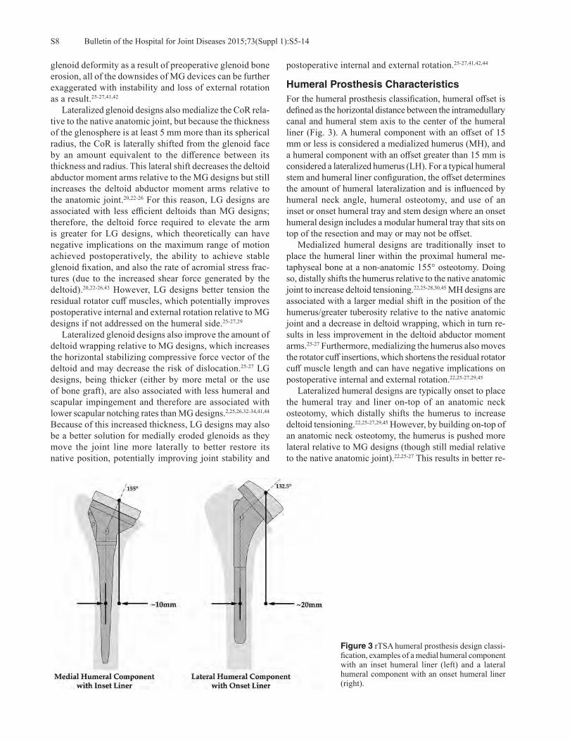
Humeral Prosthesis CharacteristicsFor the humeral prosthesis classification, humeral offset is defined as the horizontal distance between the intramedullary canal and humeral stem axis to the center of the humeral liner (Fig. 3). A humeral component with an offset of 15 mm or less is considered a medialized humerus (MH), and a humeral component with an offset greater than 15 mm is considered a lateralized humerus (LH). For a typical humeral stem and humeral liner configuration, the offset determines the amount of humeral lateralization and is influenced by humeral neck angle, humeral osteotomy, and use of an inset or onset humeral tray and stem design where an onset humeral design includes a modular humeral tray that sits on top of the resection and may or may not be offset. Medialized humeral designs are traditionally inset to place the humeral liner within the proximal humeral me-taphyseal bone at a non-anatomic 155° osteotomy. Doing so, distally shifts the humerus relative to the native anatomic joint to increase deltoid tensioning.22,25-28,30,45 MH designs are associated with a larger medial shift in the position of the humerus/greater tuberosity relative to the native anatomic joint and a decrease in deltoid wrapping, which in turn re-sults in less improvement in the deltoid abductor moment arms.25-27 Furthermore, medializing the humerus also moves the rotator cuff insertions, which shortens the residual rotator cuff muscle length and can have negative implications on postoperative internal and external rotation.22,25-27,29,45 Lateralized humeral designs are typically onset to place the humeral tray and liner on-top of an anatomic neck osteotomy, which distally shifts the humerus to increase deltoid tensioning.22,25-27,29,45 However, by building on-top of an anatomic neck osteotomy, the humerus is pushed more lateral relative to MG designs (though still medial relative to the native anatomic joint).22,25-27 This results in better re-
Figure 3 rTSA humeral prosthesis design classi-fication, examples of a medial humeral component with an inset humeral liner (left) and a lateral humeral component with an onset humeral liner (right).

S9Bulletin of the Hospital for Joint Diseases 2015;73(Suppl 1):S5-14
sidual rotator cuff tensioning and better deltoid wrapping to improve stability, which also lengthens the deltoid moment arm to improve joint efficiency.22,25-27 If a LH design is onset, it may also function as a platform humeral stem, which has numerous clinical advantages and inherent efficiencies.25-26,46
Combined Glenoid and Humeral ImpactWhile the design characteristics of the glenoid and humeral prostheses individually are important to understand, the impact of mating together these devices is the most critical aspect of this classification system25-26 (Fig. 4). Combined MG/MH devices accentuate the negative attributes of joint medialization and have been shown to require subscapularis repair in order to maintain stability.47,48 Due to the amount of medialization, MG/MH designs are discouraged in the clinical setting of an uncorrected glenoid deformity as a result of preoperative glenoid bone erosion.41,42,44 In such cases, bone graft may be required behind the glenoid with a MG/MH prosthesis to convert it to a LG/MH design con-figuration.27,41,44 A LG/MH device can utilize its more lateral
glenoid position with a more medial humeral position to better position the joint line to tension the residual rotator cuff and improve deltoid wrapping.22,25-27,29 Since the overall construct is relatively lateralized, it can be more stable and may not require subscapularis repair for stability.25,26,48,49 However, the resulting deltoid abductor moment arm of the LG/MH construct is less than that of MG/LH designs due to its more lateralized CoR.20,22-26 A MG/LH device can use the more lateral humeral position to compensate for the relative joint medialization caused by the thinner MG, thereby better tensioning the residual rotator cuff, better restoring deltoid wrapping, and further increasing the del-toid abductor moment arms.22,25-27 The more lateral humeral position of the MG/LH device can also be configured to have a reduced scapular notching rate relative to MG/MH designs.25,26,32,33,50,51 A fourth potential rTSA combination is the LG/LH design; the clinical results of this configuration have not yet been reported. Theoretically, it can achieve the same (or potentially better) residual rotator cuff tensioning and deltoid wrapping as a function of its lateral humeral
Figure 4 rTSA prosthesis design classification system to describe different prosthesis combinations of glenoid and humeral offsets. Repre-sentative examples from left to right: medial glenoid/medial humerus, lateral glenoid/medial humerus, and medial glenoid/lateral humerus.
Figure 5 Representative images of the computer muscle model, from left to right: 36 mm Grammont MG/MH, 32 mm RSP® LG/MH, 38 mm Equinoxe® MG/LH, and 36 mm Ascend® MG/LH.
Bulletin of the Hospital for Joint Diseases 2015;73(Suppl 1):S5-14S10
placement; however, it will have inherently shorter deltoid abductor moment arms than MG/LH designs (due to its more lateral CoR) and also may place the shoulder muscles under too much tension. As a result of this most lateral configu-ration, perhaps the ideal clinical application for a LG/LH designs would be patients with severe glenoid bone erosion.
Illustrating ExampleTo simulate the combined impact of each of these design characteristics and rTSA prosthesis configurations on joint position, a 3D computer muscle model is presented (Fig. 5). This model and method have been previously utilized to quantify the impact of different prosthetic designs, glenoid bone deformities, humeral implantation techniques, and
glenoid implantation techniques on muscle lengths and deltoid wrapping.21,22,24,27,32,33,42,51 Furthermore, given the modularity of newer humeral prosthesis designs (which have multiple options for humeral neck angle or multiple offsets with eccentric trays), it is important for the ortho-paedic surgeon utilizing these devices to understand the biomechanical consequences of these different implant positions and orientations. To illustrate these concepts, the 3D muscle model compared the Grammont Delta III (MG/MH), the DJO RSP® (LG/MH), the BIO-RSA® (LG/MH), the Exactech Equinoxe® (MG/LH; 0 and 5 mm humeral tray thicknesses), and the Tornier Ascend® (MG/LH; non-offset, ± 1.5 mm, and ± 3.5 mm offset) to quantify how each device impacted the muscle lengths of eight different shoulder
Table 2 Change in CoR and Humerus Position for Each Reverse Shoulder Design and Implantation Technique Relative to Normal Anatomic Shoulder
Medial Shift in CoR
Inferior Shift in CoR
Medial Shift in Humerus
Inferior Shift in Humerus
36 mm Grammont (MG/MH) 28.3 mm 8.0 mm 21.5 mm 30.2 mm36 mm Grammont, BIO-RSA® (LG/MH) 19.2 mm 8.0 mm 12.4 mm 30.1 mm32 mm Neutral RSP® (LG/MH) 20.0 mm 6.9 mm 11.7 mm 25.3 mm36 mm Ascend®, 0 mm tray offset (MG/LH) 28.3 mm 8.0 mm 11.8 mm 39.4 mm36 mm Ascend®, 1.5 mm offset (12 o’clock tray position), (MG/LH) 28.3 mm 8.0 mm 12.8 mm 40.4 mm36 mm Ascend®, 1.5 mm offset (6 o’clock tray position), (MG/LH) 28.3 mm 8.0 mm 10.8mm 38.4 mm36 mm Ascend®, 3.5 mm offset (12 o’clock tray position), (MG/LH) 28.3 mm 8.0 mm 14.1 mm 41.7 mm36 mm Ascend®, 3.5 mm offset (6 o’clock tray position), (MG/LH) 28.3 mm 8.0 mm 9.5 mm 37.0 mm38 mm Equinoxe®, 0 mm tray (MG/LH) 27.1 mm 4.5 mm 9.1 mm 34.8 mm38 mm Equinoxe®, 5 mm tray (MG/LH) 27.1 mm 4.5 mm 5.7 mm 38.4 mm
Table 3 Deltoid Wrapping and Average Change in Muscle Tension for Each Reverse Shoulder Relative to Normal Anatomic Shoulder during Scapular Abduction
Deltoid Wrapping
AngleAnt
DeltoidMid
DeltoidPost
Deltoid Subscap InfraspinTeres Major
Teres Minor
Pec Major
Normal Shoulder 48° 0.0% 0.0% 0.0% 0.0% 0.0% 0.0% 0.0% 0.0%36 mm Grammont (MG/MH) 8° 4.7% 4.8% 1.7% -11.2% -12.8% -11.0% -20.5% 2.2%36 mm Grammont, BIO-RSA® (LG/MH) 28° 7.2% 7.8% 5.0% -4.6% -6.4% -5.4% -10.9% 4.8%
32 mm Neutral RSP® (LG/MH) 28° 6.2% 7.0% 4.6% -3.9% -5.6% -4.5% -9.7% 3.6%36 mm Ascend®, 0 mm tray offset (MG/LH)
29° 8.6% 9.5% 6.8% -2.4% -4.2% -3.4% -7.5% 6.1%
36 mm Ascend®, 1.5 mm offset (12 o’clock tray position), (MG/LH)
27° 9.1% 10.1% 7.2% -2.5% -4.5% -3.7% -8.0% 6.4%
36 mm Ascend®, 1.5 mm offset (6 o’clock tray position), (MG/LH)
31° 8.1% 8.9% 6.4% -2.2% -3.9% -3.2% -6.9% 5.8%
36 mm Ascend®, 3.5 mm offset (12 o’clock tray position), (MG/LH)
24° 9.7% 10.9% 7.5% -2.7% -5.0% -4.0% -8.7% 6.8%
36 mm Ascend®, 3.5 mm offset (6 o’clock tray position), (MG/LH)
34° 7.4% 8.1% 5.9% -2.0% -3.4% -2.8% -6.1% 5.5%
38 mm Equinoxe®, 0 mm tray (MG/LH) 40° 7.3% 8.2% 6.3% 0.0% -1.6% -1.1% -3.5% 5.1%38 mm Equinoxe®, 5 mm tray (MG/LH) 80° 9.0% 10.1% 8.2% 3.1% 1.4% 1.5% 1.1% 6.8%

S11Bulletin of the Hospital for Joint Diseases 2015;73(Suppl 1):S5-14
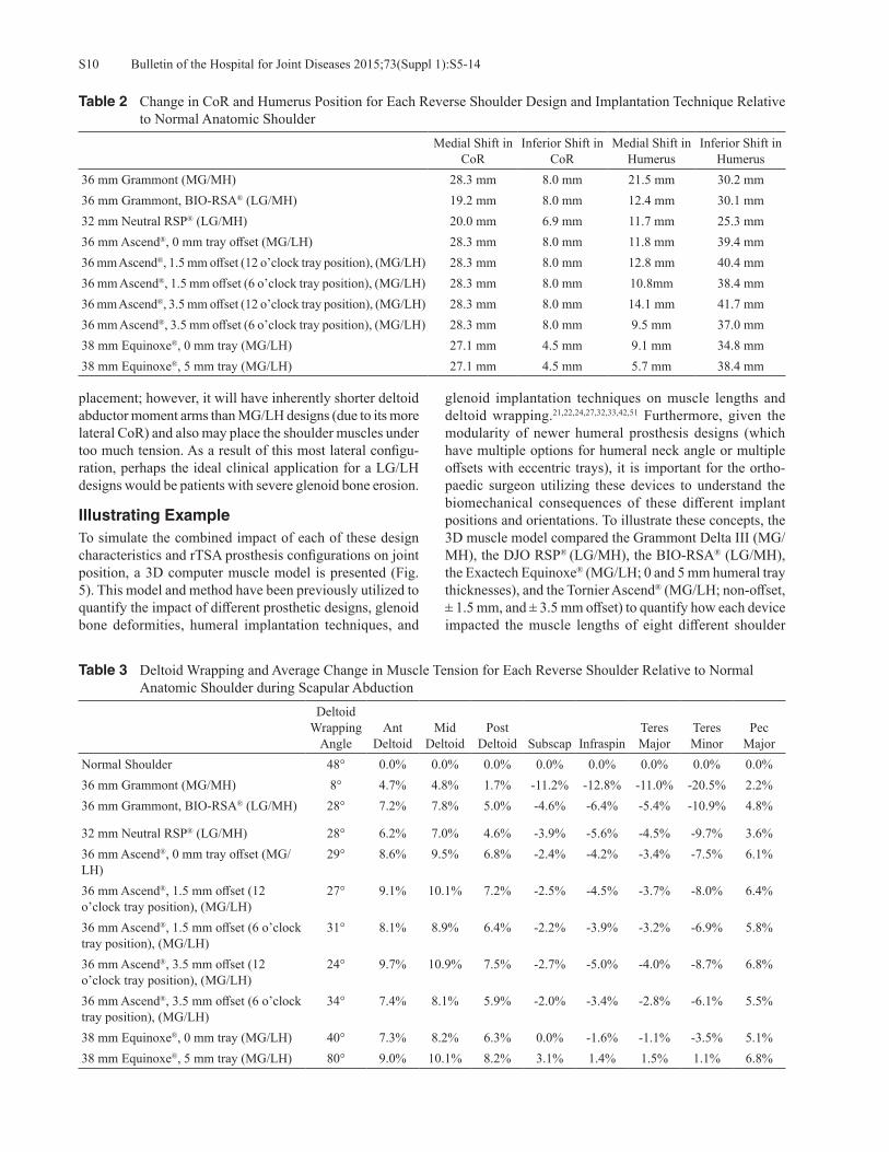
muscles during three different motions (abduction in the scapular plane, internal rotation with the arm at the side, and external rotation with the arm at the side). To standardize and allow for a direct comparison, each glenoid device was implanted identically with the baseplate aligned with the inferior glenoid rim in 0° tilt, and each humeral component was implanted in 20° retroversion. Table 2 presents how the CoR and humeral position change for each prosthesis design relative to the native ana-tomic shoulder. Table 1 demonstrates that all MG designs
are associated with a 27 mm to 28 mm medial shift in the CoR, while the LG designs are associated with only a 19 mm to 20 mm medial shift relative to the native CoR posi-tion of this computer model. Similarly, the MG/MH design was associated with the most medial humeral configuration with a 20 mm medial shift, while the LG/MH designs only medialize the humerus by 12 mm, and the (non-offset) MG/LH designs only medialize the humerus by 9 mm to 11 mm, relative to the normal anatomic relationship. Comparing the offset tray configurations demonstrates that the humerus can
Table 4 AverageMuscle Length Relative to Normal Shoulder as Each Reverse Shoulder is Internally Rotated from 0° to 40° with the Arm at 0° Abduction
Ant Deltoid
Mid Deltoid
Post Deltoid Subscap Infraspin
Teres Major
Teres Minor
Pec Major
Normal Shoulder 0.0% 0.0% 0.0% 0.0% 0.0% 0.0% 0.0% 0.0%36 mm Grammont (MG/MH) 13.4% 15.6% 9.7% -18.7% -19.7% -22.0% -32.0% 5.6%36 mm Grammont, BIO-RSA® (LG/MH) 13.5% 15.6% 11.2% -12.0% -13.7% -14.7% -22.6% 7.2%32 mm Neutral RSP® (LG/MH) 12.4% 14.7% 10.7% -10.8% -12.6% -13.1% -21.0% 5.8%36 mm Ascend®, 0 mm tray offset (MG/LH) 17.6% 20.8% 16.0% -11.1% -14.4% -13.7% -23.1% 9.3%36 mm Ascend®, 1.5 mm offset (12 o’clock tray position), (MG/LH)
18.1% 21.3% 16.3% -11.7% -15.0% -14.5% -24.1% 9.7%
36 mm Ascend®, 1.5 mm offset (6 o’clock tray position), (MG/LH)
17.1% 20.2% 15.6% -10.5% -13.7% -13.0% -22.2% 8.9%
36 mm Ascend®, 3.5 mm offset (12 o’clock tray position), (MG/LH)
18.7% 22.0% 16.7% -12.5% -15.9% -15.4% -25.4% 10.2%
36 mm Ascend®, 3.5 mm offset (6 o’clock tray position), (MG/LH)
16.4% 19.6% 15.2% -9.7% -12.8% -12.0% -20.8% 8.5%
38 mm Equinoxe®, 0 mm tray (MG/LH) 15.4% 18.4% 14.5% -8.5% -11.7% -10.4% -19.1% 7.5%38 mm Equinoxe®, 5 mm tray (MG/LH) 17.0% 20.5% 16.9% -5.9% -9.8% -7.6% -16.0% 8.9%Color Coding denotes muscle shortening > 10% (Yellow), > 20% (Orange), and > 30% (Red).
Table 5 Average Muscle Length Relative to Normal Shoulder as Each Reverse Shoulder is Externally Rotated from 0° to 40° with the Arm at 0° Abduction
Ant Deltoid
Mid Deltoid
Post Deltoid Subscap Infraspin
Teres Major
Teres Minor
Pec Major
Normal Shoulder 0.0% 0.0% 0.0% 0.0% 0.0% 0.0% 0.0% 0.0%36 mm Grammont (MG/MH) 13.6% 15.7% 10.1% -17.3% -21.0% -21.6% -36.9% 6.8%36 mm Grammont, BIO-RSA® (LG/MH) 13.8% 15.7% 11.6% -11.0% -14.6% -14.5% -26.4% 8.3%32 mm Neutral RSP® (LG/MH) 12.8% 14.7% 11.0% -10.1% -13.6% -13.2% -24.7% 7.4%36 mm Ascend®, 0 mm tray offset (MG/LH) 18.6% 20.7% 16.1% -10.6% -15.0% -14.8% -26.1% 12.8%36 mm Ascend®, 1.5 mm offset (12 o’clock tray position), (MG/LH)
19.0% 21.2% 16.5% -11.1% -15.8% -15.4% -27.3% 12.8%
36 mm Ascend®, 1.5 mm offset (6 o’clock tray position), (MG/LH)
18.2% 20.2% 15.7% -10.0% -14.3% -14.2% -24.9% 12.7%
36 mm Ascend®, 3.5 mm offset (12 o’clock tray position), (MG/LH)
19.5% 22.0% 17.0% -11.8% -16.8% -16.2% -28.8% 12.9%
36 mm Ascend®, 3.5 mm offset (6 o’clock tray position), (MG/LH)
17.7% 19.5% 15.3% -9.3% -13.3% -13.3% -23.3% 12.7%
38 mm Equinoxe®, 0 mm tray (MG/LH) 16.6% 18.3% 14.3% -8.5% -12.4% -12.3% -22.4% 11.4%38 mm Equinoxe®, 5 mm tray (MG/LH) 18.5% 20.3% 16.6% -6.2% -10.5% -9.9% -18.8% 13.5%Color coding denotes muscle shortening > 10% (Yellow), > 20% (Orange), and > 30% (Red).
Bulletin of the Hospital for Joint Diseases 2015;73(Suppl 1):S5-14S12
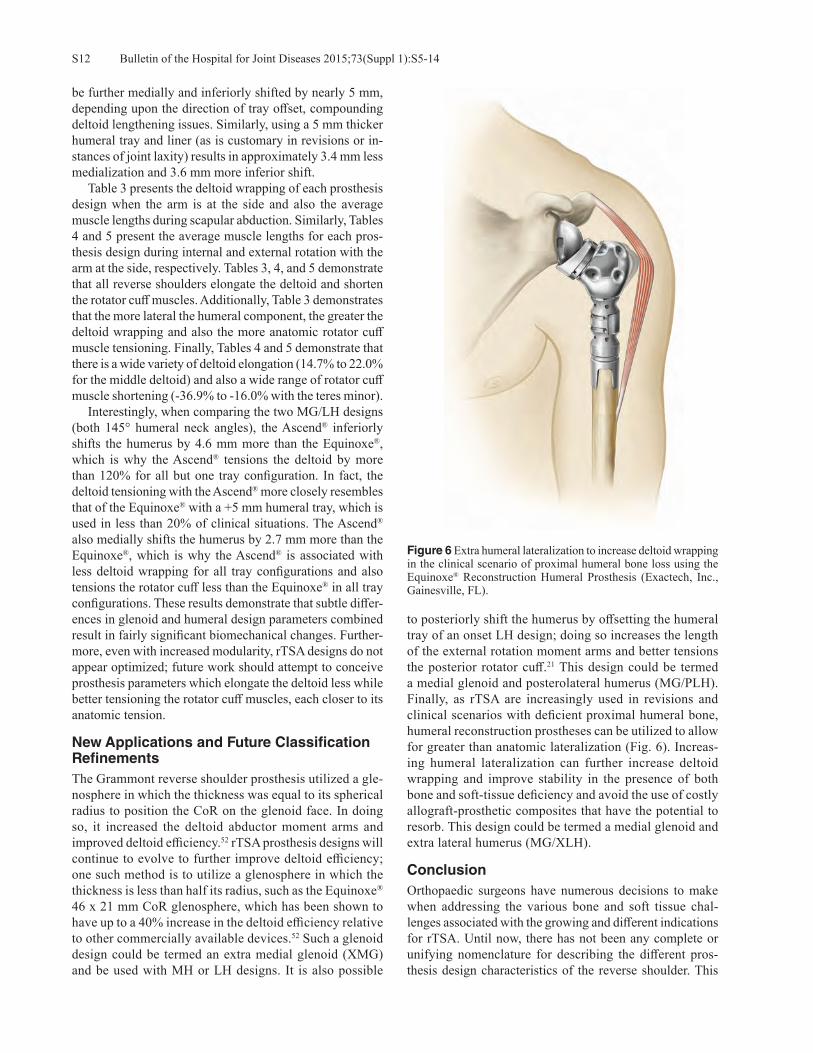
Figure 6 Extra humeral lateralization to increase deltoid wrapping in the clinical scenario of proximal humeral bone loss using the Equinoxe® Reconstruction Humeral Prosthesis (Exactech, Inc., Gainesville, FL).
be further medially and inferiorly shifted by nearly 5 mm, depending upon the direction of tray offset, compounding deltoid lengthening issues. Similarly, using a 5 mm thicker humeral tray and liner (as is customary in revisions or in-stances of joint laxity) results in approximately 3.4 mm less medialization and 3.6 mm more inferior shift. Table 3 presents the deltoid wrapping of each prosthesis design when the arm is at the side and also the average muscle lengths during scapular abduction. Similarly, Tables 4 and 5 present the average muscle lengths for each pros-thesis design during internal and external rotation with the arm at the side, respectively. Tables 3, 4, and 5 demonstrate that all reverse shoulders elongate the deltoid and shorten the rotator cuff muscles. Additionally, Table 3 demonstrates that the more lateral the humeral component, the greater the deltoid wrapping and also the more anatomic rotator cuff muscle tensioning. Finally, Tables 4 and 5 demonstrate that there is a wide variety of deltoid elongation (14.7% to 22.0% for the middle deltoid) and also a wide range of rotator cuff muscle shortening (-36.9% to -16.0% with the teres minor). Interestingly, when comparing the two MG/LH designs (both 145° humeral neck angles), the Ascend® inferiorly shifts the humerus by 4.6 mm more than the Equinoxe®, which is why the Ascend® tensions the deltoid by more than 120% for all but one tray configuration. In fact, the deltoid tensioning with the Ascend® more closely resembles that of the Equinoxe® with a +5 mm humeral tray, which is used in less than 20% of clinical situations. The Ascend® also medially shifts the humerus by 2.7 mm more than the Equinoxe®, which is why the Ascend® is associated with less deltoid wrapping for all tray configurations and also tensions the rotator cuff less than the Equinoxe® in all tray configurations. These results demonstrate that subtle differ-ences in glenoid and humeral design parameters combined result in fairly significant biomechanical changes. Further-more, even with increased modularity, rTSA designs do not appear optimized; future work should attempt to conceive prosthesis parameters which elongate the deltoid less while better tensioning the rotator cuff muscles, each closer to its anatomic tension.
New Applications and Future Classification RefinementsThe Grammont reverse shoulder prosthesis utilized a gle-nosphere in which the thickness was equal to its spherical radius to position the CoR on the glenoid face. In doing so, it increased the deltoid abductor moment arms and improved deltoid efficiency.52 rTSA prosthesis designs will continue to evolve to further improve deltoid efficiency; one such method is to utilize a glenosphere in which the thickness is less than half its radius, such as the Equinoxe® 46 x 21 mm CoR glenosphere, which has been shown to have up to a 40% increase in the deltoid efficiency relative to other commercially available devices.52 Such a glenoid design could be termed an extra medial glenoid (XMG) and be used with MH or LH designs. It is also possible
to posteriorly shift the humerus by offsetting the humeral tray of an onset LH design; doing so increases the length of the external rotation moment arms and better tensions the posterior rotator cuff.21 This design could be termed a medial glenoid and posterolateral humerus (MG/PLH). Finally, as rTSA are increasingly used in revisions and clinical scenarios with deficient proximal humeral bone, humeral reconstruction prostheses can be utilized to allow for greater than anatomic lateralization (Fig. 6). Increas-ing humeral lateralization can further increase deltoid wrapping and improve stability in the presence of both bone and soft-tissue deficiency and avoid the use of costly allograft-prosthetic composites that have the potential to resorb. This design could be termed a medial glenoid and extra lateral humerus (MG/XLH).
ConclusionOrthopaedic surgeons have numerous decisions to make when addressing the various bone and soft tissue chal-lenges associated with the growing and different indications for rTSA. Until now, there has not been any complete or unifying nomenclature for describing the different pros-thesis design characteristics of the reverse shoulder. This

S13Bulletin of the Hospital for Joint Diseases 2015;73(Suppl 1):S5-14
classification system25,26 is both descriptively helpful and clinically useful as it can discern quantifiable differences in prosthesis design types and can be used to guide surgeons in their choice of an rTSA.
Conflict of Interest StatementHoward Routman, D.O., is a consultant for Exactech, Inc., Gainesville, Florida. Pierre-Henri Flurin, M.D., Thomas W. Wright, M.D., and Joseph D. Zuckerman, M.D., are consultants for Exactech, Inc., and receive royalties on products related to this article. Matthew A. Hamilton, Ph.D., and Christopher P. Roche, M.S., M.B.A., are employed by Exactech, Inc.
References1. Sirveaux F, Favard L, Oudet D, et al. Grammont inverted
total shoulder arthroplasty in the treatment of glenohumeral osteoarthritis with massive rupture of the cuff. J Bone Joint Surg Br. 2004 Apr;86(3):388-95.
2. Frankle M, Siegal S, Pupello D, et al. The reverse shoulder prosthesis for glenohumeral arthritis associated with severe rotator cuff deficiency. A minimum two-year follow-up study of sixty patients. J Bone Joint Surg Am. 2005 Aug;87(8):1697-705.
3. Werner C, Steinmann PA, Gilbart M, Gerber C. Treatment of painful pseudoparesis due to irreparable rotator cuff dysfunc-tion with the Delta III reverse ball and socket total shoulder prosthesis. J Bone Joint Surg Am. 2005 Jul;87(7):1476-86.
4. Boileau P, Watkinson D, Hatzidakis AM, Hovorka I. The Grammont reverse shoulder prosthesis: results in cuff tear ar-thritis, fracture sequelae, and revision arthroplasty. J Shoulder Elbow Surg. 2006 Sep-Oct;15(5):527-40.
5. Wall B, Nové-Josserand L, O’Connor DP, et al. Reverse total shoulder arthroplasty: a review of results according to etiol-ogy. J Bone Joint Surg Am. 2007 Jul;89(7):1476-85.
6. Stechel A, Fuhrmann U, Irlenbusch L, et al. Reversed shoulder arthroplasty in cuff tear arthritis, fracture sequelae, and revi-sion arthroplasty. Acta Orthop. 2010 Jun;81(3):367-72.
7. Smith CD, Guyver P, Bunker TD. Indications for reverse shoulder replacement, a systematic review. J Bone Joint Surg Br. 2012 May;9(5):577-83.
8. Mizuno N, Denard PJ, Raiss P, Walch G. Reverse total shoul-der arthroplasty for primary glenohumeral osteoarthritis in patients with a biconcave glenoid. J Bone Joint Surg Am. 2013 Jul 17;95(14):1297-304.
9. Jiang JJ, Toor AS, Shi LL, Koh JL. Analysis of perioperative complications in patients after total shoulder arthroplasty and reverse total shoulder arthroplasty. J Shoulder Elbow Surg. 2014 Dec;23(12):1852-9.
10. Roche CP, Diep P, Hamilton MA, et al. Comparison of bone removed with reverse total shoulder arthroplasty. Bull Hosp Jt Dis (2013). 2013;71 Suppl 2:S36-40.
11. Nigro PT, Gutiérrez S, Frankle MA. Improving glenoid-side load sharing in a virtual reverse shoulder arthroplasty model. J Shoulder Elbow Surg. 2013 Jul;22(7):954-62.
12. Roche CP, Stroud NJ, Martin BL, et al. Achieving fixation in glenoids with superior wear using reverse shoulder arthro-plasty. J Shoulder Elbow Surg. 2013 Dec;22(12):1695-701.
13. Roche CP, Stroud NJ, Flurin PH, et al. Reverse shoulder glenoid baseplate fixation: a comparison of flat-back versus
curved-back designs and oval versus circular designs with 2 different offset glenospheres. J Shoulder Elbow Surg. 2014 Sep;23(9):1388-94.
14. Stroud N, DiPaola MJ, Flurin PH, Roche CP. Reverse shoulder glenoid loosening: an evaluation of the initial fixation associ-ated with six different reverse shoulder designs. Bull Hosp Jt Dis (2013). 2013;71 Suppl 2:S12-7.
15. Stroud NJ, DiPaola MJ, Martin BL, et al. Initial glenoid fixation using two different reverse shoulder designs with an equivalent center of rotation in a low-density and high-density bone substitute. J Shoulder Elbow Surg. 2013 Nov;22(11):1573-9.
16. Terrier A, Reist A, Merlini F, Farron A. Simulated joint and muscle forces in reversed and anatomic shoulder prostheses. J Bone Joint Surg Br. 2008 Jun;90(6):751-6.
17. Kontaxis A, Johnson GR. The biomechanics of reverse anat-omy shoulder replacement--a modelling study. Clin Biomech (Bristol, Avon). 2009 Mar;24(3):254-60.
18. Ackland DC, Roshan-Zamir S, Richardson M, Pandy MG. Moment arms of the shoulder musculature after reverse total shoulder arthroplasty. J Bone Joint Surg Am. 2010 May;92(5):1221-30.
19. Ackland DC, Richardson M, Pandy MG. Axial rotation moment arms of the shoulder musculature after reverse total shoulder arthroplasty. J Bone Joint Surg Am. 2012 Oct 17;94(20):1886-95.
20. Henninger HB, Barg A, Anderson AE, et al. Effect of lat-eral offset center of rotation in reverse total shoulder arthro-plasty: a biomechanical study. J Shoulder Elbow Surg. 2012 Sep;21(9):1128-35.
21. Roche CP, Hamilton MA, Diep P, et al. Design rationale for a posterior/superior offset reverse shoulder prosthesis. Bull Hosp Jt Dis (2013). 2013;71 Suppl 2:S18-24.
22. Hamilton MA, Roche CP, Diep P, et al. Effect of prosthesis design on muscle length and moment arms in reverse total shoulder arthroplasty. Bull Hosp Jt Dis (2013). 2013;71 Suppl 2:S31-5.
23. Langohr GD, Giles JW, Athwal GS, Johnson JA. The effect of glenosphere diameter in reverse shoulder arthroplasty on muscle force, joint load, and range of motion. J Shoulder Elbow Surg. 2015 Jun;24(6):972-9.
24. Hamilton MA, Diep P, Roche C, et al. Effect of reverse shoul-der design philosophy on muscle moment arms. J Orthop Res. 2015 Apr;33(4):605-13.
25. Roche C, Crosby L. Kinematics and biomechanics of reverse total shoulder arthroplasty. In: Nicholson GP (ed): Orthopae-dic Knowledge Update: Shoulder and Elbow. Rosemont, IL: American Academy of Orthpaedic Surgeons 2013, pp. 45-54.
26. Roche C, Hansen M, Flurin PH, et al. Biomechanical Summary of Reverse Shoulder Arthroplasty. Anima-tion. AAOS Orthopaedic Video Theater. OVT-34. 2015. Available at: http://orthoportal.aaos.org/emedia/abstract.aspx?resource=EMEDIA_OSVL_15_34.
27. Roche CP, Diep P, Hamilton M, et al. Impact of inferior glenoid tilt, humeral retroversion, bone grafting, and de-sign parameters on muscle length and deltoid wrapping in reverse shoulder arthroplasty. Bull Hosp Jt Dis (2013). 2013;71(4):284-93.
28. Lädermann A, Williams MD, Melis B, et al. Objective evalua-tion of lengthening in reverse shoulder arthroplasty. J Shoulder Elbow Surg. 2009 Jul-Aug;18(4):588-95.
Bulletin of the Hospital for Joint Diseases 2015;73(Suppl 1):S5-14S14
29. Herrmann S, König C, Heller M, et al. Reverse shoulder ar-throplasty leads to significant biomechanical changes in the remaining rotator cuff. J Orthop Surg Res. 2011 Aug 16;6:42.
30. Lädermann A, Walch G, Lubbeke A, et al. Influence of arm lengthening in reverse shoulder arthroplasty. J Shoulder Elbow Surg. 2012 Mar;21(3):336-41.
31. Nyffeler RW, Werner CM, Gerber C. Biomechanical relevance of glenoid component positioning in the reverse Delta III total shoulder prosthesis. J Shoulder Elbow Surg. 2005 Sep-Oct;14(5):524-8.
32. Roche C, Flurin PH, Wright T, Zuckerman JD. Geometric analysis of the Grammont reverse shoulder prosthesis: an evaluation of the relationship between prosthetic design parameters and clinical failure modes. Presented at the 2006 ISTA Meeting, New York, New York, October 6-9, 2006.
33. Roche C, Flurin PH, Wright T, et al. An evaluation of the relationships between reverse shoulder design parameters and range of motion, impingement, and stability. J Shoulder Elbow Surg. 2009 Sep-Oct;18(5):734-41.
34. Gutiérrez S, Comiskey CA 4th, Luo ZP, et al. Range of impingement-free abduction and adduction deficit after reverse shoulder arthroplasty. Hierarchy of surgical and implant-design-related factors. J Bone Joint Surg Am. 2008 Dec;90(12):2606-15.
35. de Wilde LF, Poncet D, Middernacht B, Ekelund A. Prosthetic overhang is the most effective way to prevent scapular con-flict in a reverse total shoulder prosthesis. Acta Orthop. 2010 Dec;81(6):719-26.
36. Karelse AT, Bhatia DN, De Wilde LF. Prosthetic component relationship of the reverse Delta III total shoulder prosthesis in the transverse plane of the body. J Shoulder Elbow Surg. 2008 Jul-Aug;17(4):602-7.
37. Kempton LB, Balasubramaniam M, Ankerson E, Wiater JM. A radiographic analysis of the effects of glenosphere posi-tion on scapular notching following reverse total shoulder arthroplasty. J Shoulder Elbow Surg. 2011 Sep;20(6):968-74.
38. Lévigne C, Garret J, Boileau P, et al. Scapular notching in reverse shoulder arthroplasty: is it important to avoid it and how? Clin Orthop Relat Res. 2011 Sep;469(9):2512-20.
39. Simovitch RW, Zumstein MA, Lohri E, et al. Predictors of scapular notching in patients managed with the Delta III reverse total shoulder replacement. J Bone Joint Surg Am. 2007 Mar;89(3):588-600.
40. Lévigne C, Boileau P, Favard L, et al. Scapular notching in reverse shoulder arthroplasty. J Shoulder Elbow Surg. 2008 Nov-Dec;17(6):925-35.
41. Norris TR, Kelly JD, Humphrey CS. Management of glenoid bone defects in revision shoulder arthroplasty: A new applica-
tion of the reverse total shoulder prosthesis. Tech Shoulder Elbow Surg. 2007;8(1):37-46.
42. Roche C, Diep P, Hamilton M, et al. Biomechanical analysis of 3 commercially available reverse shoulder designs in a normal and medially eroded scapula. Presented at the 59th Annual Orthopaedic Research Society Meeting. San Antonio, Texas, January 26-29, 2013.
43. Levy JC, Anderson C, Samson A. Classification of postop-erative acromial fractures following reverse shoulder arthro-plasty. J Bone Joint Surg Am. 2013 Aug 7;95(15):e104.
44. Boileau P, Moineau G, Roussanne Y, O’Shea K. Bony increased-offset reversed shoulder arthroplasty: minimizing scapular impingement while maximizing glenoid fixation. Clin Orthop Relat Res. 2011 Sep;469(9):2558-67.
45. Boileau P, Watkinson DJ, Hatzidakis AM, Balg F. Grammont reverse prosthesis: design, rationale, and biomechanics. J Shoulder Elbow Surg. 2005 Jan-Feb;14(1 Suppl S):147S-161S.
46. Crosby L ,Wright T. Revision total shoulder arthroplasty with and without humeral stem removal: how much of a difference does it make in the overall results? Presented at the 23rd Annual BESS Scientific Meeting, Torquay, UK, June 13-15, 2012.
47. Edwards TB, Williams MD, Labriola JE, et al. Subscapularis insufficiency and the risk of shoulder dislocation after reverse shoulder arthroplasty. J Shoulder Elbow Surg. 2009 Nov-Dec;18(6):892-6.
48. Routman HD. The role of subscapularis repair in reverse total shoulder arthroplasty. Bull Hosp Jt Dis (2013). 2013;71 Suppl 2:108-12.
49. Clark JC, Ritchie J, Song FS, et al. Complication rates, dislo-cation, pain, and postoperative range of motion after reverse shoulder arthroplasty in patients with and without repair of the subscapularis. J Shoulder Elbow Surg. 2012 Jan;21(1):36-41.
50. Roche CP, Marczuk Y, Wright TW, et al. Scapular notching and osteophyte formation after reverse shoulder replacement: Radiological analysis of implant position in male and female patients. Bone Joint J. 2013 Apr;95-B(4):530-5.
51. Roche CP, Marczuk Y, Wright TW, et al. Scapular notching in reverse shoulder arthroplasty: validation of a computer impingement model. Bull Hosp Jt Dis (2013). 2013;71(4):278-83.
52. Roche, C, Diep P, Hamilton M, et al. Optimizing deltoid efficiency with reverse shoulder arthroplasty using a novel glenosphere geometry. Presented at the 61st Annual Ortho-paedic Research Society Meeting, Las Vegas, Nevada, March 28-31, 2015.

S15Bulletin of the Hospital for Joint Diseases 2015;73(Suppl 1):S15-20
Friedman R, Stroud N, Glattke K, Flurin P-H, Wright TW, Zuckerman JD, Roche CP. The impact of posterior wear on reverse shoulder glenoid fixation. Bull Hosp Jt Dis. 2015;73(Suppl 1):S15-20.
Abstract
Introduction: Achieving glenoid fixation with posterior bone loss can be challenging. The purpose of this study was to quantify the impact of two different sizes of posterior gle-noid defects (10° and 20°) on reverse shoulder arthroplasty (rTSA) glenoid baseplate fixation and determine if utilizing different sizes of posterior augmented baseplates (8° and 16°) with off-axis reaming provides comparable fixation to using a standard baseplate with different amounts of ec-centric reaming. Methods: We quantified the impact of 10° and 20° poste-rior glenoid defects on rTSA baseplate fixation in composite scapulae using the ASTM F2028-14 rTSA glenoid loosening test method. Forty-two total implants (N = 7 for each size defect and for each type of baseplate) were tested at 750 N for 10,000 cycles. Baseplate displacement was measured before and after cyclic loading in the superior-inferior and anterior-posterior directions. Statistical analysis was performed with a two-tailed unpaired Student’s t-test (significance defined as p < 0.05) to compare prosthesis displacements relative to each scapula (10° and 20° posterior defects for each type of baseplate versus the non-defect control) before and after cyclic loading. Results: All glenoid baseplates remained well-fixed after cyclic loading in composite scapulae without a defect and
in scapulae with posterior defects. Increased pre- and post-cyclic displacement was observed with increased posterior defect size and differences in displacement were observed between standard and augmented baseplates. Augmented baseplates were observed to remove significantly less bone than standard baseplates when correcting posterior defects, regardless of size. Discussion: Both standard baseplates with eccentric reaming and two different sizes of augmented baseplates with off-axis reaming successfully maintained fixation following cyclic loading in composite scapula with corrected 10° and 20° posterior glenoid defects. Augmented glenoids may be more advantageous long-term from a fixation perspective as they preserve more subchondral glenoid bone due to the minimal reaming occurring by the off-axis method. Mid and long-term clinical follow-up comparisons of outcomes are necessary between these two techniques.
Glenoid bone loss with pathological retroversion is commonly seen in patients with severe glenohu-meral arthritis resulting from many different under-
lying etiologies, most commonly late-stage osteoarthritis. Loss of glenoid bone stock and abnormal bony architecture necessitate reconstruction during total shoulder arthroplasty (TSA), whether with an anatomic (aTSA) or reverse (rTSA) total shoulder arthroplasty prosthetic design. Glenoid reconstruction requires meticulous preoperative planning with quantitative measurements to determine the extent and location of the correction or augmentation required in Type B and C glenoids according to the Walch classification.1 Preoperative computerized tomography (CT) scans play an important role in evaluating patients preoperatively for a TSA, as plain radiographs and intraoperative visualization are not accurate or reliable. A CT scan with 3D reconstruc-tion provides an accurate depiction of the bony anatomy, the extent of the patient’s bone loss, and the need for modifica-
The Impact of Posterior Wear on Reverse Shoulder Glenoid Fixation
Richard Friedman, M.D., F.R.C.S.C., Nicholas Stroud, M.S., Kaycee Glattke, B.S., Pierre-Henri Flurin, M.D., Thomas W. Wright, M.D., Joseph D. Zuckerman, M.D., and Christopher P. Roche, M.S., M.B.A.
Richard Friedman, M.D., F.R.C.S.C., Medical University of South Carolina, Charleston, South Carolina. Nicholas Stroud, M.S., Kaycee Glattke, B.S., and Christopher P. Roche, M.S., M.B.A., Exactech, Gainesville, Florida. Pierre-Henri Flurin, M.D., Bordeaux-Merignac Clinique du Sport, Merignac, France. Thomas W. Wright, M.D., Department of Orthopaedics and Rehabilitation, University of Florida, Gainesville, Florida. Joseph D. Zuckerman, M.D., Department of Orthopaedic Surgery, Hospital for Joint Diseases, NYU Langone Medical Center, New York, New York. Correspondence: Christopher P. Roche, M.S., M.B.A., Exactech, Inc., 2320 NW 66th Court, Gainesville, Florida 32653; chris. [email protected].

Bulletin of the Hospital for Joint Diseases 2015;73(Suppl 1):S15-20S16
tion of the surgical procedure. Various techniques have been described to quantify the amount of bone loss.2
For the long-term success of a TSA, excessive retrover-sion needs to be corrected at the time of the arthroplasty. If not, there are significant consequences that will increase the risk of glenoid component failure. Previous studies have shown that the stresses at the bone cement interface increase with retroversion, thereby increasing the rate of aseptic loosening.3-5 Also, there are increased contact pressures that can wear the glenoid component polyethylene and also increased implant micromotion with increased retroversion, all of which can contribute to aseptic loosening as well.3-5
Glenoid reconstruction for severe bone loss with increased retroversion in the face of severe arthritis can be challenging. Previous surgical techniques to correct the retroversion have included eccentric reaming of the high anterior side, but this can result in loss of valuable glenoid bone stock, downsizing of the glenoid component as it is medialized, and loss of sub-chondral bone that can impact long-term glenoid component fixation. Posterior bone grafting can also be performed, but it is technically very difficult, and the presence of cement may affect osteointegration; the graft is subject to resorption and loosening over time as well.5-12
A posterior augmented component with off-axis ream-ing can be used to correct excessive glenoid retroversion in both aTSA and rTSA.8-12,13 Advantages over current methods include decreasing the amount of reaming, thereby saving valuable glenoid bone stock; eliminating the need for bone grafting; better restoring the native joint line to rebalance the joint; and converting shear forces to compressive forces down the glenoid neck, thereby protecting the bone cement and bone prosthesis interfaces. Practical considerations exist for correcting excessive retroversion and enabling the sur-geon to overcome technical challenges to do the arthroplasty correctly. In these situations, the glenoid faces away from the surgeon and makes the procedure technical very difficult to perform. It is also more difficult to seat the glenosphere on the baseplate with excessive retroversion, so correcting this helps to ensure a well-done arthroplasty. Some have suggested that rTSA be used in cases of severe retroversion combined with excessive posterior subluxation, the B2 glenoid according to the Walch classification.14 To correct the excessive retroversion, either eccentric reaming or off-axis reaming with an augmented glenoid baseplate can be used. rTSA, as compared to aTSA, has some poten-tial to have better mid- and long-term outcomes in patients with severe posterior wear because the conforming reverse articulation may provide better joint stability for patients with a posterior subluxed humeral head.14 Additionally, the uncemented metal rTSA baseplate with supplemental screw fixation may provide better long-term glenoid fixation in patients with severe posterior wear than a cemented aTSA glenoid due to the need to eccentrically ream the glenoid to correct the deformity.5-7,14 We conducted this study to quantify the impact of two sizes of B2 posterior glenoid defects (10° and 20°) on rTSA
glenoid baseplate fixation in a composite scapula model us-ing the recently approved ASTM F2028-14 reverse shoulder glenoid loosening test method.15 The aim of this study is two-fold: 1. to quantify the impact of posterior glenoid defect size on rTSA glenoid baseplate fixation and 2. to determine if utilizing different sizes of posterior augmented baseplates with off-axis reaming provides comparable fixation to using a standard baseplate with different amounts of eccentric reaming.
Materials and MethodsForty-two 38 mm rTSA implants (Equinoxe®, Exactech, Inc.) were tested in a fourth generation composite, dual density scapula (Pacific Research, Inc., Vashon, WA) with a 1.63 g/cm3 “cortical” shell and a 0.27 g/cm3 “cancellous” interior structure. This substrate provides a representative substitute for the density, strength, and modulus of glenoid cortical and cancellous bone in the recipient patient population for rTSA.16-19 Posterior biconcave defects of 10° and 20° were reamed into the composite scapulae with the aid of a can-nulated reamer and custom jig. The 10° and 20° posterior defects were intended to simulate two different sizes of B2 glenoids, which may be treated clinically with rTSA.1,14 Baseplate fixation in the 10° and 20° posterior glenoid defect scapulae were assessed using both standard rTSA gle-noid baseplates with eccentric reaming (N = 7 for each size defect) and using 8° posterior augment glenoid baseplates with off-axis reaming (N = 7 for each size defect) (Fig. 1).
Figure 1 Eccentric versus off-axis reaming to correct a posterior glenoid defect, acromion removed in image to improve glenoid visualization.

S17Bulletin of the Hospital for Joint Diseases 2015;73(Suppl 1):S15-20
Sixteen degrees posterior augment glenoid baseplates were also tested in the 20° posterior defect scapulae (N = 7). All devices were compared to composite scapulae without a glenoid defect (N = 7) before and after cyclic loading, which functions as the control in the study. Initial fixation of each glenoid baseplate was achieved using four (one superior, one inferior, one anterior, and one posterior), 4.5 mm x 30 mm diameter poly-axial locking compression screws and a press-fit tapered cage peg. After assembly, the composite scapulae were cut and potted with bone cement. This study was conducted according to ASTM F2028-14 in two phases.15 This rTSA glenoid loosening test method has been used previously to identify differences in fixation between screw configurations,20 medialized and lateralized center of rotation,21-23 glenoid baseplate designs,22-24 scapular defects and wear patterns,13,25 and different densities of sub-strates.20,23,24 The first phase was the displacement test (Fig. 2). It measured the fixation of the rTSA glenoid baseplate in the composite scapula before and after the application of 10,000 cycles of dynamic loading for 55° at 0.5 Hz. In the displacement test, the axial test machine (Instron Corp.
Norwood, Mass., resolution of 1 micron) and three digital indicators (Mitutoyo, Japan, resolution of 1 micron) quan-tified the glenoid baseplate displacement relative to the composite scapula as a compressive (50 N) and shear (357 N) load was applied. The compressive axial load was applied perpendicular to the reverse glenoid baseplate, and the shear load was applied parallel to the face of the glenoid baseplate along its superior-inferior (SI) axis and then repeated along the anterior-posterior (AP) axis. Dial indicators were used to subtract out any compliance of the test construct. The second phase is the cyclic test. The cyclic test simulates the primary motion of rTSA; that is, the abduction motion generated by the deltoid. The humeral liner and scapulae with rTSA baseplate and glenosphere were positioned in the biaxial testing apparatus and aligned along the SI axis of the glenoid baseplate (Fig. 3). A 750 N axial load was constantly applied through the center of the humeral liner as the scapulae with rTSA baseplate and glenosphere were rotated about the humeral component with a stepper motor to create a sinusoidal angular displacement profile encompass-ing an arc of 55° at 0.5 Hz for 10,000 cycles. The components
Figure 2 Representative image of the rTSA gle-noid loosening displacement test.
Figure 3 Representative image of the rTSA gle-noid loosening cyclic test.

Bulletin of the Hospital for Joint Diseases 2015;73(Suppl 1):S15-20S18
were cooled with a continuous jet of air with no lubrication. Statistical analysis was performed by means of a two-tailed unpaired Student’s t-test (significance defined as p < 0.05) to compare prosthesis displacements relative to each scapula (10° and 20° posterior defects for each type of baseplate vs. the non-defect control) before and after cyclic loading.
ResultsAll rTSA glenoid baseplates remained well-fixed after cyclic loading in composite scapulae without a defect and with each 10° and 20° posterior glenoid defects, regardless of baseplate type or reaming method. Augmented glenoid baseplates removed less of the composite bone when cor-recting each size defect, with 16° baseplates removing the least bone when correcting the largest defect (Fig. 4). Table 1 presents the average pre- and post-cyclic glenoid baseplate displacement in scapulae with 10° posterior glenoid defects. As presented, both standard baseplates with 10° eccentric reaming and 8° posterior augment baseplates with off-axis reaming were associated with significantly larger SI and AP post-cyclic displacement than the standard baseplate in com-posite scapula without a defect. Additionally, 8° posterior augment baseplates in 10° defect composite scapulae were associated with significantly less SI post-cyclic displacement than standard baseplates with 10° eccentric reaming, though no difference was noted in post-cyclic AP displacement.
Table 2 presents the average pre- and post-cyclic glenoid baseplate displacement in scapulae with 20° posterior gle-noid defects. As presented, each of the standard baseplates with 20° eccentric reaming, 8° posterior augment baseplates with off-axis reaming, and 16° posterior augment baseplates with off-axis reaming were associated with significantly larger SI and AP post-cyclic displacement than the stan-dard baseplate in composite without a defect. Additionally, standard baseplates in 20° defect composite scapulae were associated with significantly less AP post-cyclic displace-ment than both the 8° and 16° posterior augment baseplates and also less SI post-cyclic displacement than 16° posterior augment baseplates. Finally, 8° posterior augment baseplates in 20° defect composite scapulae were associated with sig-nificantly less SI post-cyclic displacement than 16° posterior augment baseplates.
DiscussionThe results of this study demonstrate that either standard baseplates with eccentric reaming or augmented baseplates with off-axis reaming can be used to maintain rTSA glenoid fixation, even in scapulae with very large posterior glenoid defects. However, using rTSA in the scapula with posterior glenoid defects generally increased the pre- and post-cyclic baseplate displacement relative to the non-defect control, regardless of baseplate type or reaming method, with larger size defects associated with greater increases in pre- and post-cyclic displacement. Some differences in fixation were noted between standard and augmented baseplates. For 10° posterior defects, aug-mented baseplates were associated with significantly less SI post-cyclic displacement than standard baseplates, though no difference was noted in AP post-cyclic displacement. However, for larger 20° posterior defects, standard base-plates were associated with significantly less AP post-cyclic displacement than both the 8° and 16° posterior augment baseplates and also less SI post-cyclic displacement than 16° posterior augment baseplates. Finally, augmented glenoid baseplates with off-axis reaming conserved more glenoid bone than standard baseplates with eccentric reaming, with more bone conserved in larger size defects. Obtaining fixation with TSA in scapula with eroded gle-noid can be challenging. When the orthopaedic surgeon is faced with posterior glenoid defects up to 10°, both standard
Table 1 Glenoid Baseplate Displacement Before and After Cyclic Loading in Scapula with 10° Posterior Glenoid Defects
Baseplate Shear Displacement (microns) SI Shear Pre SI Shear Post AP Shear Pre AP Shear PostNo Posterior Defect, Standard Baseplate 73.9 ± 15.9 72.2 ± 15.6 171.4 ± 63.9 158.2 ± 45.010° Posterior Defect, Standard Baseplate 112.8 ± 17.8 120.9 ± 18.3 214.3 ± 25.9 226.5 ± 34.110° Posterior Defect, 8° Augmented Baseplate 116.8 ± 47.1 100.9 ± 15.2 224.1 ± 67.8 223.3 ± 53.2P-value (No Defect vs. 10° Defect, Std Baseplate) 0.0010 0.0002 0.1250 0.0076P-value (No Defect vs. 10° Defect, 8° Post Aug Baseplate) 0.0412 0.0046 0.1601 0.0294P-value (10° Std Baseplate vs. 10° Defect, 8° Post Aug Baseplate) 0.8344 0.0459 0.7281 0.8945
Figure 4 Representative images after testing of the composite scapula glenoid with a 20° posterior glenoid defect. Left image: bone removed using the standard baseplate with eccentric reaming to correct defect. Right image: bone removed using the 16° poste-rior augmented baseplate with off-axis reaming to correct defect.

S19Bulletin of the Hospital for Joint Diseases 2015;73(Suppl 1):S15-20
baseplates with eccentric reaming and augmented baseplates with off-axis reaming can effectively maintain rTSA glenoid fixation following correction of the defect. The results of this study and others8-10,13 also demonstrate that augmented glenoids remove less bone when correcting defects. In doing so, augmented glenoids better maintain the native joint line, which has the potential to better restore anatomic muscle lengths, as demonstrated previously with augmented aTSA glenoid components when used in different sizes of posterior glenoid defects.10 However, the results of this study are less clear for orthopaedic surgeons when faced with posterior glenoid defects up to 20°. Standard baseplates with eccentric ream-ing were associated with significantly less displacement than augmented baseplates in these very large defects; although, every standard and augmented baseplate tested with this glenoid loosening methodology completed the cyclic test without failure. This glenoid loosening methodology has previously been utilized to test six different commercially available designs, and three of those six failed to pass this cyclic test when evaluated in low density polyurethane blocks without any defects.23,24 Recent mid and long-term clinical follow-ups from Walch and coworkers has demon-strated significant increases in radiographic loosening and subsidence rates in aTSA patients when the glenoid was reamed more aggressively as compared to those that were not.26,27 Several other studies have recommended upper limits (e.g., 10° to 15°) on the amount of retroversion that can be corrected with eccentric reaming alone.6,7,28 Thus, the significantly lower displacements observed with the standard baseplate in these very large defects may be offset clinically by the substantial removal of bone by eccentric reaming. Augmented glenoids may be more advantageous long-term from a fixation perspective as they preserve more subchondral glenoid bone due to the minimal reaming oc-curring by the off-axis method. Mid and long-term clinical follow-up comparisons of outcomes are necessary between
these two techniques. This rTSA baseplate fixation study in posterior glenoid defects has some limitations. First, we used a composite scapulae model rather than matched pair cadaveric speci-mens to reduce variables related to cortical and cancellous density and bone thickness. Additionally, we desired identi-cal morphology to ensure that the created posterior glenoid defects were the same in each tested specimen. Second, this model only evaluated initial fixation and does not simu-late the impact of any osseous integration; it is unknown whether implant osteointegration in the clinical situation may mitigate early fixation vulnerabilities. Finally, this study does not evaluate different screw patterns or the impact of using additional screws. The baseplate utilized in this test permits use of up to six poly-axial locking compression screws, and the use of additional screws or different patterns of screws may improve fixation. Future work should investigate the ability of different implanta-tion and positioning techniques, placement of additional screws, or utilizing different screw patterns to mitigate any early fixation vulnerabilities in this posterior glenoid defect model.
ConclusionsThis study demonstrates that both standard baseplates with eccentric reaming and two different sizes of augmented baseplates with off-axis reaming successfully maintained fixation following cyclic loading in composite scapulae with corrected 10° and 20° posterior glenoid defects. In-creased pre- and post-cyclic displacement was observed with increased posterior defect size, and differences in dis-placement were observed between standard and augmented baseplates. Augmented glenoid baseplates with off-axis reaming may be more advantageous long-term from a fixa-tion perspective as they preserve more subchondral glenoid bone due to the minimal reaming occurring by the off-axis method, which was observed to remove significantly less
Table 2 Glenoid Baseplate Displacement Before and After Cyclic Loading in Scapula with 20° Posterior Glenoid Defects
Baseplate Shear Displacement (microns) SI Shear Pre SI Shear Post AP Shear Pre AP Shear PostNo Posterior Defect, Standard Baseplate 73.9 ± 15.9 72.2 ± 15.6 171.4 ± 63.9 158.2 ± 45.020° Posterior Defect, Standard Baseplate 103.6 ± 16.3 103.2 ± 13.0 219.7 ± 81.4 220.3 ± 55.620° Posterior Defect, 8° Augmented Baseplate 142.5 ± 57.9 113.1 ± 20.3 361.1 ± 125.1 327.2 ± 103.920° Posterior Defect, 16° Augmented Baseplate 138.5 ± 31.2 162.9 ± 32.9 371.7 ± 140.3 393.2 ± 140.0P-value (No Defect vs. 20° Defect, Std Baseplate) 0.0047 0.0017 0.2400 0.0403P-value (No Defect vs. 20° Defect, 8° Post Aug Baseplate) 0.0105 0.0012 0.0038 0.0019P-value (No Defect vs. 20° Defect, 16° Post Aug Baseplate) 0.0004 < 0.0001 0.0049 0.0012P-value (20° Defect, Std Baseplate vs. 20° Defect, 8° Post Aug Baseplate)
0.1129 0.2977 0.0276 0.0336
P-value (20° Defect, Std Baseplate vs. 20° Defect, 16° Post Aug Baseplate)
0.0223 0.0008 0.0290 0.0104
P-value (20° Defect, 8° Post Aug vs. 20° Defect, 16° Post Aug Baseplate)
0.8747 0.0052 0.8837 0.3361

Bulletin of the Hospital for Joint Diseases 2015;73(Suppl 1):S15-20S20
bone than the eccentric reaming method to correct the de-fect. Clinical follow-up comparisons of outcomes between these techniques are necessary.
Conflict of Interest StatementRichard Friedman, M.D., F.R.C.S.C., is a consultant for Ex-actech, Inc. Pierre-Henri Flurin, M.D., Thomas W. Wright, M.D., and Joseph D. Zuckerman, M.D., are consultants for Exactech, Inc. and receive royalties on products related to this article. Nicholas Stroud, M.S., Kaycee Glattke, B.S., Christopher P. Roche, M.S., M.B.A., are employed by Ex-actech, Inc., Gainesville, Florida.
DisclosureThe 16° posterior augment rTSA is not currently approved by the FDA for use in the United States.
References1. Walch G, Badet R, Boulahia A, Khoury A. Morphologic
study of the glenoid in primary glenohumeral osteoarthritis. J Arthroplasty. 1999 Sep;14(6):756-60.
2. Friedman RJ, Hawthorne KB, Genez BM. The use of com-puterized tomography in the measurement of glenoid version. J Bone Joint Surg Am. 1992 Aug;74(7):1032-7.
3. Hopkins AR, Hansen UN, Amis AA, Emery R. The effects of glenoid component alignment variations on cement mantle stresses in total shoulder arthroplasty. J Shoulder Elbow Surg. 2004 Nov-Dec;13(6):668-75.
4. Terrier A, Büchler P, Farron A. Bone-cement interface of the glenoid component: stress analysis for varying cement thick-ness. Clin Biomech(Bristol, Avon). 2005 Aug;20(7):710-7.
5. Farron A, Terrier A, Büchler P. Risks of loosening of a pros-thetic glenoid implanted in retroversion. J Shoulder Elbow Surg. 2006 Jul-Aug;15(4):521-6.
6. Gillespie R, Lyons R, Lazarus M. Eccentric reaming in total shoulder arthroplasty: a cadaveric study. Orthopedics. 2009 Jan;32(1):21.
7. Clavert P, Millett PJ, Warner JJ. Glenoid resurfacing: what are the limits to asymmetric reaming for posterior erosion? J Shoulder Elbow Surg. 2007 Nov-Dec;16(6):843-8.
8. Hermida JC, Flores-Hernandez C, Hoenecke HR, D’Lima DD. Augmented wedge-shaped glenoid component for the correction of glenoid retroversion: a finite element analysis. J Shoulder Elbow Surg. 2014 Mar;23(3):347-54.
9. Kersten AD, Flores-Hernandez C, Hoenecke HR, D’Lima DD. Posterior augmented glenoid designs preserve more bone in biconcave glenoids. J Shoulder Elbow Surg. 2015 Jul;24(7):1135-41.
10. Roche CP, Diep P, Grey SG, Flurin PH. Biomechanical impact of posterior glenoid wear on anatomic total shoulder arthro-plasty. Bull Hosp Jt Dis (2013). 2013;71 Suppl 2:S5-11.
11. Jones RB. Addressing glenoid erosion in anatomic total shoulder arthroplasty. Bull Hosp Jt Dis (2013). 2013;71 Suppl 2:S46-50. Review.
12. Gilot GJ. Addressing glenoid erosion in reverse total shoulder arthroplasty. Bull Hosp Jt Dis (2013). 2013;71 Suppl 2:S51-3. Review.
13. Roche CP, Stroud NJ, Martin BL, et al. Achieving fixation in glenoids with superior wear using reverse shoulder arthro-plasty. J Shoulder Elbow Surg. 2013 Dec;22(12):1695-701.
14. Mizuno N, Denard PJ, Raiss P, Walch G. Reverse total shoul-der arthroplasty for primary glenohumeral osteoarthritis in patients with a biconcave glenoid. J Bone Joint Surg Am. 2013 Jul 17;95(14):1297-304.
15. ASTM F2028-14. Standard Test Methods for Dynamic Evaluation of Glenoid Loosening or Disassociation. West Conshohocken, PA: ASTM International, 2014.
16. Anglin C, Tolhurst P, Wyss UP, Pichora DR. Glenoid cancellous bone strength and modulus. J Biomech. 1999 Oct;32(10):1091-7.
17. Kalouche I, Crépin J, Abdelmoumen S, et al. Mechanical properties of glenoid cancellous bone. Clin Biomech (Bristol, Avon). 2010 May;25(4):292-298.
18. Lehtinen JT, Tingart MJ, Apreleva M, Warner JJP. Total, tra-becular, and cortical bone mineral density in different regions of the glenoid. J Shoulder Elbow Surg. 2004 Jun;13(3):344-8.
19. Mimar R, Limb D, Hall RM. Evaluation of the mechanical and architectural properties of glenoid bone. J Shoulder Elbow Surg. 2008 Apr;17(2):336-41.
20. Roche C, Flurin PH, Wright T, et al. effect of varying screw configuration and bone density on reverse shoulder glenoid fixation following cyclic loading. Presented at the 54th Annual Orthopaedic Research Society Meeting, San Francisco, CA, March 2-5, 2008.
21. Roche C, Steffens J, Flurin PH, et al. Reverse Shoulder Gle-noid Loosening Test Method: an analysis of fixation between two different offset glenospheres. Presented at the 57th Annual Orthopaedic Research Society Meeting, Long Beach, CA, January 13-16, 2011.
22. Roche CP, Stroud NJ, Flurin PH, et al. Reverse shoulder glenoid baseplate fixation: a comparison of flat-back versus curved-back designs and oval versus circular designs with 2 different offset glenospheres. J Shoulder Elbow Surg. 2014 Sep;23(9):1388-94.
23. Stroud N, DiPaola MJ, Flurin PH, Roche CP. Reverse shoulder glenoid loosening: an evaluation of the initial fixation associ-ated with six different reverse shoulder designs. Bull Hosp Jt Dis (2013). 2013;71 Suppl 2:S12-7.
24. Stroud NJ, DiPaola MJ, Martin BL, et al. Initial glenoid fixation using two different reverse shoulder designs with an equivalent center of rotation in a low-density and high-density bone substitute. J Shoulder Elbow Surg. 2013 Nov; 22(11):1573-9.
25. Roche CP, Stroud NJ, Martin BL, et al. The impact of scapular notching on reverse shoulder glenoid fixation. J Shoulder Elbow Surg. 2013 Jul;22(7):963-70.
26. Walch G, Young AA, Melis B, et al. Results of a convex-back cemented keeled glenoid component in primary osteoarthritis: multicenter study with a follow-up greater than 5 years. J Shoulder Elbow Surg. 2011 Apr;20(3):385-94.
27. Walch G, Young AA, Boileau P, et al. Patterns of loosening of polyethylene keeled glenoid components after shoulder arthroplasty for primary osteoarthritis: results of a multicenter study with more than five years of follow-up. J Bone Joint Surg Am. 2012 Jan 18;94(2):145-50.
28. Nowak DD, Bahu MJ, Gardner TR, et al. Simulation of sur-gical glenoid resurfacing using three-dimensional computed tomography of the arthritic glenohumeral joint: the amount of glenoid retroversion that can be corrected. J Shoulder Elbow Surg. 2009. Sep-Oct;18(5):680-8.

S21Bulletin of the Hospital for Joint Diseases 2015;73(Suppl 1):S21-7
Hansen ML, Nayak A, Narayanan MS, Worhacz K, Stowell R, Jacofsky MC, Roche CP. Role of subscapularis repair on muscle force requirements with reverse shoulder arthroplasty. Bull Hosp Jt Dis. 2015;73(Suppl 1):S21-7.
Abstract
Concomitant repair of the subscapularis with reverse shoul-der arthroplasty (rTSA) is controversial. To evaluate the biomechanical impact of subscapularis repair with rTSA, a cadaveric shoulder controller quantified the muscle forces required to elevate the arm during scapular abduction with the elbow flexed at 90°. The results of this study demonstrate that concomitant subscapularis repair with rTSA creates a biomechanically unfavorable condition during arm eleva-tion. Specifically, repair of the subscapularis significantly increased the force required by the deltoid and posterior rotator cuff and also significantly increased the joint reaction force relative to when the subscapularis was not repaired. These results also demonstrated that both the 42 mm Gram-mont and 42 mm Equinoxe® rTSA prostheses significantly decreased the mean force required by the posterior rotator cuff and also significantly decreased the mean joint reaction force over the range of motion relative to the native joint with a rotator cuff tear (supraspinatus). As the posterior rota-tor cuff is often compromised in patients undergoing rTSA, patients may not be able to sustain these elevated forces in the infraspinatus and teres minor required to counteract the adduction and internal rotation moments generated by the subscapularis during activities of daily living. Similarly, the elevated posterior deltoid force and joint reaction loads
could be deleterious to the long-term life of the prosthesis and can also increase the risk of loosening and fractures. For all these reasons, rTSA functional outcomes may be compromised if the subscapularis is repaired.
Reverse total shoulder arthroplasty (rTSA) has found great success over the last decade, evolving from a salvage procedure used in difficult situations to
a more mainstream procedure. This procedure has been widely accepted to treat conditions, such as massive rotator cuff tears, cuff tear arthropathy, and proximal humerus frac-tures.1-9 Distinct from anatomic total shoulder arthroplasty (aTSA), rTSA is inherently more constrained as a result of its conforming articular geometry and inverted anatomic concavities. Specifically, the rTSA prosthesis has a convex glenoid and concave humerus that function as a fixed fulcrum articulation to prevent superior humeral migration. While this inverted arrangement is common to all rTSA prosthesis designs, significant inter-manufacturer variability exists, particularly as it relates to the position of the joint center of rotation (CoR) and the position of the humerus.10-14 Given the variety of different rTSA prosthesis design configura-tions available in the worldwide marketplace, the anatomic shoulder can be altered by rTSA as follows: 1. 15 mm to 30 mm medial shift in the CoR, 2. a 25 mm to 40 mm distal shift in the position of the humerus, and 3. a 10 mm to 25 mm medial shift in the position of the humerus.12 Such joint configuration changes modify the normal anatomic relation-ships between the origins and insertions of the shoulder muscles, altering their resting lengths, operational envelopes, and moment arms.10-24 These geometric changes have been demonstrated to improve deltoid efficiency10-22; however, their effect on the rotator cuff is not as clearly known.12,23-25
Of particular interest is the effect of different rTSA prosthesis designs on the performance of the subscapularis muscle. Controversy exists surrounding concomitant repair
Role of Subscapularis Repair on Muscle Force Requirements with Reverse Shoulder Arthroplasty
Matthew L. Hansen, M.D., Aniruddh Nayak, M.S., Madusudanan Sathia Narayanan, Ph.D., Kellen Worhacz, B.S., Richard Stowell, M.D., Marc C. Jacofsky, Ph.D., and Christopher P. Roche, M.S., M.B.A.
Matthew L. Hansen, M.D., Mezona Orthopaedic Clinic, Gilbert, Arizona. Aniruddh Nayak, M.S., Madusudanan Sathia Narayanan, Ph.D., Kellen Worhacz, B.S., The MORE Foundation, Phoenix, Arizona. Richard Stowell, M.D., The CORE Institute, Phoenix, Arizona. Marc C. Jacofsky, Ph.D., MORE Foundation and the CORE Institute, Phoenix, Arizona. Christopher P. Roche, M.S., M.B.A., Exactech, Gainesville, Florida. Correspondence: Christopher P. Roche, M.S., M.B.A., Exactech, Inc., 2320 NW 66th Court, Gainesville, Florida 32653; chris. [email protected].

Bulletin of the Hospital for Joint Diseases 2015;73(Suppl 1):S21-7S22
of the subscapularis with rTSA. It has been reported that repair of the subscapularis is necessary to ensure joint stabil-ity,26 and indeed orthopaedic surgeons are very accustomed to repairing the subscapularis in aTSA. However, this muscle has relatively little potential for increased excursion, and the integrity of these repairs after rTSA is questionable given the typical involvement in the pathology. Prosthesis designs that are associated with a more medial humeral position have been shown to have greater risk for instability if the subscapularis is not repaired,10,11,25,26 whereas prosthesis designs that position the humerus more laterally have been shown to not have any increased risk of instability when the subscapularis is not repaired and are associated with more anatomic muscle tensioning.10-12,25,27 The native subscapularis muscle is known to operate in a biphasic manner. The superior portion inserts on the lesser tuberosity proximal to the CoR causing abduction, whereas the inferior portion inserts distal to the CoR causing ad-duction.25,28-30 These two portions of the subscapularis also have separate innervation.31-33 By shifting the position of the humerus in an inferior-medial position with rTSA, the proximal subscapularis is generally shifted below the CoR, converting it into an adductor for most of the range of motion (ROM). Its action as an adductor would, therefore, counter-act the work of the deltoid, increasing its force required to elevate the arm and also increasing the overall joint reaction force, which may be deleterious to the long-term life of the device.10,11,25 It is hypothesized that concomitant subscapularis repair will increase the deltoid force required for abduction, the posterior rotator cuff required for external rotation, and the overall joint reaction force with rTSA. To that end, the purpose of this cadaveric shoulder controller study is to quantify the different muscle forces required to abduct the arm in the scapular plane from 20° to 70° when the elbow is flexed at 90° and compare in three different scenarios: 1. supraspinatus tear in the native anatomic shoulder, 2. two different RTSA prostheses designs, and 3. subscapularis repair with rTSA.
MethodologyA second-generation cadaveric shoulder controller that utilizes simulated neuromuscular control was used for this study. This shoulder controller is similar to that described by Hansen and coworkers with upgrades and a greater refresh rate for the control loop.34 Stepper motors (Industrial Devices Corporation, Salem, New Hampshire) actuate cables that are attached to the rotator cuff tendons and deltoid tuberosity. Force transducers measure the tension developed in each cable as active closed-loop position, and orientation control algorithms control each motor. This active controller al-lows the cadaveric model to simulate in vivo glenohumeral kinematics and muscle loads during various motions. As presently configured, the controller utilizes active opti-cal markers (Northern Digital, Inc., Waterloo, Ontario,
Canada) to track motion, and a six-axis load cell measures the resultant joint reaction force at the glenohumeral joint. Specifically, the cable and eyelet configurations simulate the three heads of the deltoid (middle, posterior, anterior), the supraspinatus, the subscapularis, the pectoralis major, the infraspinatus, and teres minor. To simulate more-physiologic joint compression and induce more-anatomic deltoid wrapping around the greater tuberosity,10-12,35-37 a deltoid surrogate model was created. Deltoid wrapping has also been demonstrated to vary with different rTSA prosthesis designs and implantation tech-niques.10-12 This muscle model was made from VytaFlex® 50 Liquid Urethane Rubber (Smooth-On, Inc.) and physically connected to three cables through three polyethylene tubes embedded within, to route the muscle lines for the anterior, middle, and posterior deltoid to the respective eyelets as shown during the ROM (Fig. 1). Five male cadaveric full upper extremity specimens (age: 65.6 ± 6.3 years) were selected with similar height and BMI (height: 71.6 ± 2.0 inches; BMI: 30.2 ± 9.8) to ensure similar anthropometrics and tested in scapular plane abduction without any artificial external constraints from 20° to 70° with the full mass of the upper extremity. The tests were performed with the elbow flexed at 90° to simulate the passive internal rotation gravitational torque associated with many activities of daily living (ADL). Five conditions were tested in 5° increments over the ROM: 1. native shoul-der, 2. native shoulder with a supraspinatus tear, 3. 42 mm Equinoxe® rTSA with subscapularis repair (as simulated by a constant 15 N subscapularis force which was previously deemed to be the minimum force necessary to maintain a stable joint using this controller38,39), 4. 42 mm Equinoxe® rTSA without subscapularis repair, and 5. a 42 mm Delta III Grammont rTSA without subscapularis repair. Five trials were performed for each condition and each trial was aver-aged. A Student’s two-tailed unpaired t-test was conducted on the mean muscle forces over the ROM for each condition where p < 0.05 deemed significance.
Figure 1 Representative image of the surrogate deltoid model used with the cadaveric shoulder controller.

S23Bulletin of the Hospital for Joint Diseases 2015;73(Suppl 1):S21-7
Tab
le 1
C
ompa
rison
of M
ean
Mus
cle
Forc
es d
urin
g Sc
apul
ar A
bduc
tion
with
the
Elbo
w F
lexe
d at
90°
Avg
Mus
cle
Forc
eM
id D
elto
idPo
st D
elto
idA
nt D
elto
idTo
tal D
elto
idIn
fras
pina
tus
Tere
s Min
orTo
tal P
oste
rior
RC
Pec
Maj
orJo
int R
eact
ion
Forc
eN
ativ
e65
.0 ±
15.
653
.4 ±
53.
438
.9 ±
8.7
157.
3 ±
55.3
77.1
± 4
.738
.4 ±
2.3
115.
5 ±
6.9
27.3
± 5
.229
6.1
± 56
.3N
ativ
e w
ith S
S Te
ar67
.8 ±
13.
364
.2 ±
30.
640
.8 ±
7.7
172.
8 ±
51.1
75.6
± 6
.537
.6 ±
3.2
113.
2 ±
9.7
32.2
±6.
629
3.4
± 56
.0%
Cha
nge
-4.3
%-2
0.3%
-4.9
%-9
.8%
1.9%
2.1%
2.0%
-17.
9%0.
9%P-
valu
e0.
6600
0.42
540.
5939
0.50
320.
5489
0.50
020.
5310
0.06
720.
9132
Nat
ive
with
SS
Tear
67.8
± 1
3.3
64.2
± 3
0.6
40.8
± 7
.717
2.8
± 51
.175
.6 ±
6.5
37.6
± 3
.211
3.2
± 9.
732
.2 ±
6.6
293.
4 ±
56.0
Equi
noxe
® w
/o S
ubsc
ap73
.1 ±
3.1
56.7
± 2
1.7
43.8
± 1
.917
3.5
± 3.
157
.4 ±
21.
928
.9 ±
10.
886
.2 ±
32.
716
.5 ±
5.5
233.
4 ±
53.2
% C
hang
e-7
.8%
11.7
%-7
.4%
-0.4
%24
.1%
23.2
%23
.8%
48.7
%20
.4%
P-va
lue
0.21
550.
5126
0.22
090.
9637
0.01
550.
0181
0.01
63<
0.00
010.
0180
Nat
ive
with
SS
Tear
67.8
± 1
3.3
64.2
± 3
0.6
40.8
± 7
.717
2.8
± 51
.175
.6 ±
6.5
37.6
± 3
.211
3.2
± 9.
732
.2 ±
6.6
293.
4 ±
56.0
Gra
mm
ont w
/o S
ubsc
ap76
.6 ±
6.3
49.1
± 1
1.6
45.5
± 3
.717
1.2
± 17
.861
.4 ±
19.
730
.6 ±
9.5
92.0
± 2
9.2
19.6
± 2
.022
2.5
± 44
.0%
Cha
nge
-13.
0%23
.5%
-11.
7%0.
9%18
.7%
18.7
%18
.7%
39.1
%24
.2%
P-va
lue
0.06
090.
3189
0.07
840.
9267
0.03
440.
0313
0.03
33<
0.00
010.
0035
Equi
noxe
® w
ith S
ubsc
ap74
.2 ±
13.
883
.0 ±
24.
044
.4 ±
8.2
201.
6 ±
14.5
87.6
± 1
6.9
43.9
± 8
.213
1.5
± 25
.125
.9 ±
8.9
324.
7 ±
43.4
Equi
noxe
® w
/o S
ubsc
ap73
.1 ±
3.1
56.7
± 2
1.7
43.8
± 1
.917
3.5
± 3.
157
.4 ±
21.
928
.9 ±
10.
886
.2 ±
32.
716
.5 ±
5.5
233.
4 ±
53.2
% C
hang
e1.
5%31
.7%
1.5%
13.9
%34
.5%
34.2
%34
.4%
36.2
%28
.1%
P-va
lue
0.79
570.
0139
0.79
510.
0008
0.00
170.
0015
0.00
160.
0075
0.00
03G
ram
mon
t w/o
Sub
scap
76.6
± 6
.349
.1 ±
11.
645
.5 ±
3.7
171.
2 ±
17.8
61.4
± 1
9.7
30.6
± 9
.592
.0 ±
29.
219
.6 ±
2.0
222.
5 ±
44.0
Equi
noxe
w/o
Sub
scap
73.1
± 3
.156
.7 ±
21.
743
.8 ±
1.9
173.
5 ±
3.1
57.4
± 2
1.9
28.9
± 1
0.8
86.2
± 3
2.7
16.5
± 5
.523
3.4
± 53
.2%
Cha
nge
4.6%
-15.
4%3.
9%-1
.3%
6.6%
5.5%
6.3%
15.7
%-4
.9%
P-va
lue
0.11
030.
3189
0.17
510.
7720
0.65
150.
7009
0.66
750.
0928
0.60
33
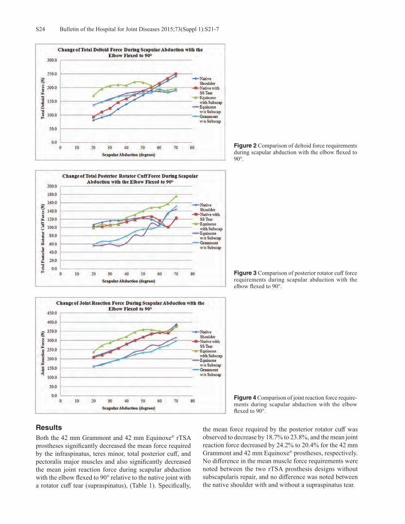
Bulletin of the Hospital for Joint Diseases 2015;73(Suppl 1):S21-7S24
ResultsBoth the 42 mm Grammont and 42 mm Equinoxe® rTSA prostheses significantly decreased the mean force required by the infraspinatus, teres minor, total posterior cuff, and pectoralis major muscles and also significantly decreased the mean joint reaction force during scapular abduction with the elbow flexed to 90° relative to the native joint with a rotator cuff tear (supraspinatus), (Table 1). Specifically,
the mean force required by the posterior rotator cuff was observed to decrease by 18.7% to 23.8%, and the mean joint reaction force decreased by 24.2% to 20.4% for the 42 mm Grammont and 42 mm Equinoxe® prostheses, respectively. No difference in the mean muscle force requirements were noted between the two rTSA prosthesis designs without subscapularis repair, and no difference was noted between the native shoulder with and without a supraspinatus tear.
Figure 3 Comparison of posterior rotator cuff force requirements during scapular abduction with the elbow flexed to 90°.
Figure 4 Comparison of joint reaction force require-ments during scapular abduction with the elbow flexed to 90°.
Figure 2 Comparison of deltoid force requirements during scapular abduction with the elbow flexed to 90°.

S25Bulletin of the Hospital for Joint Diseases 2015;73(Suppl 1):S21-7
Repair of the subscapularis with rTSA significantly increased the force required by the posterior deltoid, total deltoid, infraspinatus, teres minor, total posterior cuff, and pectoralis major muscles and also significantly increased the mean joint reaction force during scapular abduction with the elbow flexed to 90° relative to when the subscapularis was not repaired (Table 1). Specifically when the subscapularis was repaired using the 42 mm Equinoxe®, the mean force required by the posterior deltoid and posterior rotator cuff increased by 31.7% to 34.4%, respectively, during the ROM. Additionally, this increased deltoid force (Fig. 2), posterior cuff force (Fig. 3), and joint reaction force (Fig. 4) were most pronounced between 20° and 60° of scapular abduction, though these increases persisted throughout the ROM.
DiscussionThe results of this cadaveric shoulder controller study dem-onstrate that repair of the subscapularis with rTSA signifi-cantly increased the force required by the posterior deltoid and posterior rotator cuff to elevate the arm when the elbow is flexed and also significantly increased the joint reaction force relative to when the subscapularis is not repaired. These results also demonstrate that both the 42 mm Gram-mont and 42 mm Equinoxe® rTSA prostheses significantly decreased the mean force required by the posterior rotator cuff and also significantly decreased the mean joint reac-tion force over the ROM relative to the native joint with a rotator cuff tear (supraspinatus). No differences in the mean muscle force requirements were noted between the two rTSA prosthesis designs without subscapularis repair, and no difference was noted between the native shoulder with and without a supraspinatus tear. These results provide support for the hypothesis that rTSA with concomitant subscapularis repair creates a bio-mechanically unfavorable condition during arm elevation. By shifting the subscapularis insertion in the inferior-medial direction below the CoR, the subscapularis converts from being primarily an abductor to being primarily an adductor throughout the ROM, counteracting the abduction torque generated by the deltoid. This explains the observations in this study that more force was required by the deltoid when the subscapularis was repaired as opposed to when the subscapularis was not repaired. We chose to perform the study with the cadaver elbow fixed in 90° of flexion to better simulate functional arm po-sitions, such as those that are required by activities of daily living (ADL). This may be a more realistic scenario because elbow flexion is required for most ADL, such as washing hair, brushing teeth, drinking from a cup, etc. As the shoul-der is abducted while the elbow is flexed, shoulder internal rotation torque is produced by gravity acting on the forearm and hand. Clinically, this internal rotation torque is manifest as hornblower’s sign and is associated with posterior rotator cuff deficiency.40 Such patients typically exhibit shoulder abduction but have difficulty with ADL that require bring-ing the hand near the head because their shoulder falls into
internal rotation. Experimental setups that test the shoulder while the elbow is extended do not have the same magnitude of internal rotation torque. Because the posterior rotator cuff and posterior deltoid produce an external rotation torque at the shoulder, these muscles oppose the internal rotation torque caused by gravity. Clinical improvement after rTSA is greater if there is some remaining functional posterior rotator cuff or if addi-tional external rotation torque is provided by other means, such as a latissimus dorsi muscle transfer to the posterior proximal humerus.41-44 If the subscapularis is intact and also producing internal rotation torque, the total magni-tude of internal rotation torque may be greater than can be overcome by the posterior cuff and the hornblower’s sign and accompanying shoulder dysfunction may be worsened. This explains the observations in this study that more force was required by the posterior cuff when the subscapularis was repaired as opposed to when the subscapularis was not repaired. Furthermore, this study showed increased joint reaction force for the subscapularis repair condition. This increased force is a result of increased co-contraction of the subscapularis, the posterior cuff, and the posterior deltoid. Elevated joint reaction forces may increase polyethylene component wear and increase risk of aseptic glenoid loos-ening, acromial stress fractures, and deltoid fatigue. These results related to increased deltoid, posterior cuff, and joint reaction force with subscapularis repair provides support for avoiding subscapularis repair with rTSA. Not repairing the subscapularis with rTSA contradicts the recommendation of Edwards and colleagues where it was reported that the instability rate increases when the subscapularis is not repaired with rTSA.26 As previously explained by Routman and associates and others, repair of the subscapularis may be dependent on prosthesis design, where rTSA designs that medialize the humerus less may be more inherently stable due to improved deltoid wrap-ping and more anatomic muscle tensioning.10-12,25 Indeed, Edwards and colleagues justification for subscapularis repair is to decrease dislocations rather than to improve external rotation strength.26 The two rTSA designs used in this study are fundamen-tally different.10-14,45-47 The Grammont design shifts the gle-noid (and CoR) medially and shifts the humerus medially. The Equinoxe® design also has a medial glenoid shift, but the design of the humeral component causes a lateral shift of the humerus compared to the native shoulder and the Gram-mont design. Because of the greater moment arm imparted to the deltoid with the Equinoxe® design, it was expected that less deltoid force would be required with this design. This effect has been observed in computer studies13,14 but could not be demonstrated in this cadaveric shoulder controller study. However, both rTSA designs did show decreased deltoid force compared to the native shoulder with rotator cuff tear. This is consistent with expectations for rTSA. It should be noted that 42 mm sizes of each device were utilized in this study to simulate the use of rTSA in these relatively
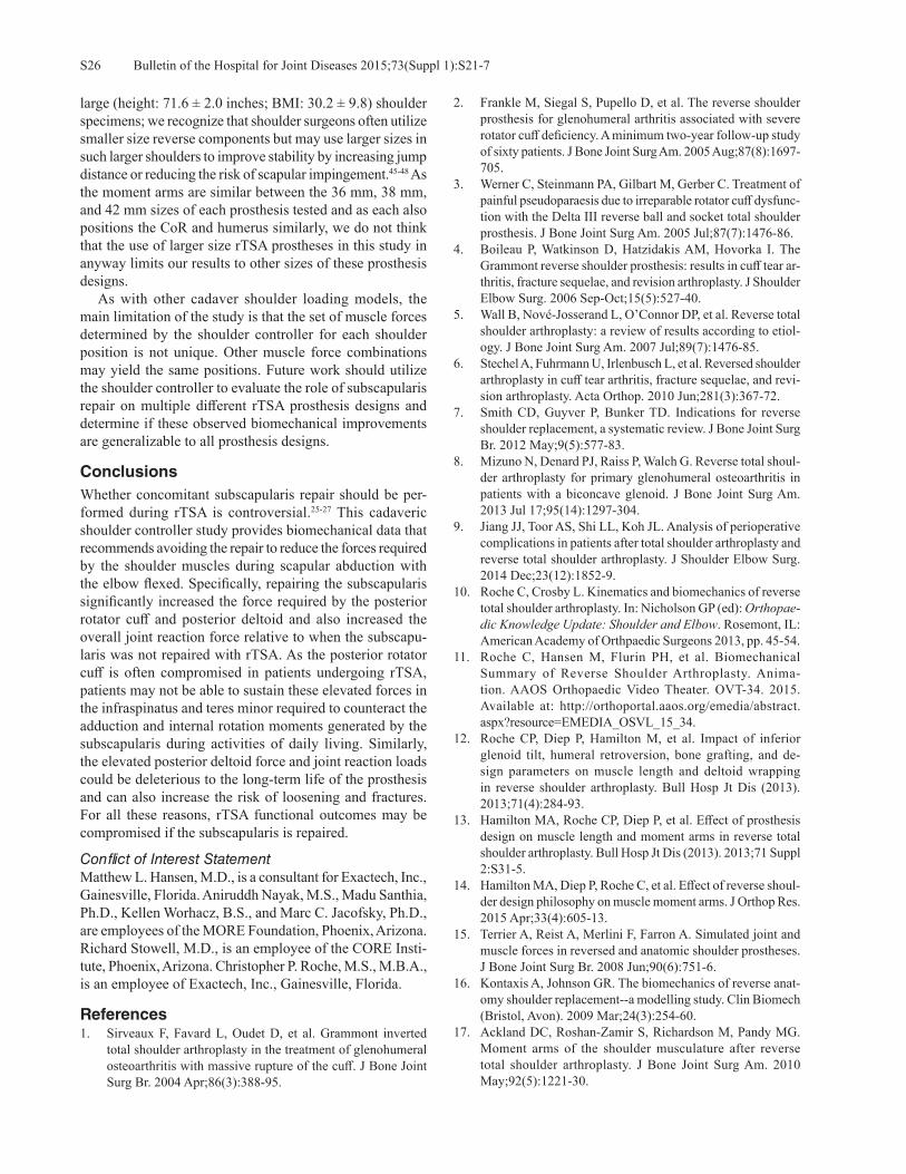
Bulletin of the Hospital for Joint Diseases 2015;73(Suppl 1):S21-7S26
large (height: 71.6 ± 2.0 inches; BMI: 30.2 ± 9.8) shoulder specimens; we recognize that shoulder surgeons often utilize smaller size reverse components but may use larger sizes in such larger shoulders to improve stability by increasing jump distance or reducing the risk of scapular impingement.45-48 As the moment arms are similar between the 36 mm, 38 mm, and 42 mm sizes of each prosthesis tested and as each also positions the CoR and humerus similarly, we do not think that the use of larger size rTSA prostheses in this study in anyway limits our results to other sizes of these prosthesis designs. As with other cadaver shoulder loading models, the main limitation of the study is that the set of muscle forces determined by the shoulder controller for each shoulder position is not unique. Other muscle force combinations may yield the same positions. Future work should utilize the shoulder controller to evaluate the role of subscapularis repair on multiple different rTSA prosthesis designs and determine if these observed biomechanical improvements are generalizable to all prosthesis designs.
ConclusionsWhether concomitant subscapularis repair should be per-formed during rTSA is controversial.25-27 This cadaveric shoulder controller study provides biomechanical data that recommends avoiding the repair to reduce the forces required by the shoulder muscles during scapular abduction with the elbow flexed. Specifically, repairing the subscapularis significantly increased the force required by the posterior rotator cuff and posterior deltoid and also increased the overall joint reaction force relative to when the subscapu-laris was not repaired with rTSA. As the posterior rotator cuff is often compromised in patients undergoing rTSA, patients may not be able to sustain these elevated forces in the infraspinatus and teres minor required to counteract the adduction and internal rotation moments generated by the subscapularis during activities of daily living. Similarly, the elevated posterior deltoid force and joint reaction loads could be deleterious to the long-term life of the prosthesis and can also increase the risk of loosening and fractures. For all these reasons, rTSA functional outcomes may be compromised if the subscapularis is repaired.
Conflict of Interest StatementMatthew L. Hansen, M.D., is a consultant for Exactech, Inc., Gainesville, Florida. Aniruddh Nayak, M.S., Madu Santhia, Ph.D., Kellen Worhacz, B.S., and Marc C. Jacofsky, Ph.D., are employees of the MORE Foundation, Phoenix, Arizona. Richard Stowell, M.D., is an employee of the CORE Insti-tute, Phoenix, Arizona. Christopher P. Roche, M.S., M.B.A., is an employee of Exactech, Inc., Gainesville, Florida.
References1. Sirveaux F, Favard L, Oudet D, et al. Grammont inverted
total shoulder arthroplasty in the treatment of glenohumeral osteoarthritis with massive rupture of the cuff. J Bone Joint Surg Br. 2004 Apr;86(3):388-95.
2. Frankle M, Siegal S, Pupello D, et al. The reverse shoulder prosthesis for glenohumeral arthritis associated with severe rotator cuff deficiency. A minimum two-year follow-up study of sixty patients. J Bone Joint Surg Am. 2005 Aug;87(8):1697-705.
3. Werner C, Steinmann PA, Gilbart M, Gerber C. Treatment of painful pseudoparaesis due to irreparable rotator cuff dysfunc-tion with the Delta III reverse ball and socket total shoulder prosthesis. J Bone Joint Surg Am. 2005 Jul;87(7):1476-86.
4. Boileau P, Watkinson D, Hatzidakis AM, Hovorka I. The Grammont reverse shoulder prosthesis: results in cuff tear ar-thritis, fracture sequelae, and revision arthroplasty. J Shoulder Elbow Surg. 2006 Sep-Oct;15(5):527-40.
5. Wall B, Nové-Josserand L, O’Connor DP, et al. Reverse total shoulder arthroplasty: a review of results according to etiol-ogy. J Bone Joint Surg Am. 2007 Jul;89(7):1476-85.
6. Stechel A, Fuhrmann U, Irlenbusch L, et al. Reversed shoulder arthroplasty in cuff tear arthritis, fracture sequelae, and revi-sion arthroplasty. Acta Orthop. 2010 Jun;281(3):367-72.
7. Smith CD, Guyver P, Bunker TD. Indications for reverse shoulder replacement, a systematic review. J Bone Joint Surg Br. 2012 May;9(5):577-83.
8. Mizuno N, Denard PJ, Raiss P, Walch G. Reverse total shoul-der arthroplasty for primary glenohumeral osteoarthritis in patients with a biconcave glenoid. J Bone Joint Surg Am. 2013 Jul 17;95(14):1297-304.
9. Jiang JJ, Toor AS, Shi LL, Koh JL. Analysis of perioperative complications in patients after total shoulder arthroplasty and reverse total shoulder arthroplasty. J Shoulder Elbow Surg. 2014 Dec;23(12):1852-9.
10. Roche C, Crosby L. Kinematics and biomechanics of reverse total shoulder arthroplasty. In: Nicholson GP (ed): Orthopae-dic Knowledge Update: Shoulder and Elbow. Rosemont, IL: American Academy of Orthpaedic Surgeons 2013, pp. 45-54.
11. Roche C, Hansen M, Flurin PH, et al. Biomechanical Summary of Reverse Shoulder Arthroplasty. Anima-tion. AAOS Orthopaedic Video Theater. OVT-34. 2015. Available at: http://orthoportal.aaos.org/emedia/abstract.aspx?resource=EMEDIA_OSVL_15_34.
12. Roche CP, Diep P, Hamilton M, et al. Impact of inferior glenoid tilt, humeral retroversion, bone grafting, and de-sign parameters on muscle length and deltoid wrapping in reverse shoulder arthroplasty. Bull Hosp Jt Dis (2013). 2013;71(4):284-93.
13. Hamilton MA, Roche CP, Diep P, et al. Effect of prosthesis design on muscle length and moment arms in reverse total shoulder arthroplasty. Bull Hosp Jt Dis (2013). 2013;71 Suppl 2:S31-5.
14. Hamilton MA, Diep P, Roche C, et al. Effect of reverse shoul-der design philosophy on muscle moment arms. J Orthop Res. 2015 Apr;33(4):605-13.
15. Terrier A, Reist A, Merlini F, Farron A. Simulated joint and muscle forces in reversed and anatomic shoulder prostheses. J Bone Joint Surg Br. 2008 Jun;90(6):751-6.
16. Kontaxis A, Johnson GR. The biomechanics of reverse anat-omy shoulder replacement--a modelling study. Clin Biomech (Bristol, Avon). 2009 Mar;24(3):254-60.
17. Ackland DC, Roshan-Zamir S, Richardson M, Pandy MG. Moment arms of the shoulder musculature after reverse total shoulder arthroplasty. J Bone Joint Surg Am. 2010 May;92(5):1221-30.

S27Bulletin of the Hospital for Joint Diseases 2015;73(Suppl 1):S21-7
18. Ackland DC, Richardson M, Pandy MG. Axial rotation moment arms of the shoulder musculature after reverse total shoulder arthroplasty. J Bone Joint Surg Am. 2012 Oct 17;94(20):1886-95.
19. Henninger HB, Barg A, Anderson AE, et al. Effect of lat-eral offset center of rotation in reverse total shoulder arthro-plasty: a biomechanical study. J Shoulder Elbow Surg. 2012 Sep;21(9):1128-35.
20. Langohr GD, Giles JW, Athwal GS, Johnson JA. The effect of glenosphere diameter in reverse shoulder arthroplasty on muscle force, joint load, and range of motion. J Shoulder Elbow Surg. 2015 Jun;24(6):972-9.
21. Lädermann A, Williams MD, Melis B, et al. Objective evalua-tion of lengthening in reverse shoulder arthroplasty. J Shoulder Elbow Surg. 2009 Jul-Aug;18(4):588-95.
22. Lädermann A, Walch G, Lubbeke A, et al. Influence of arm lengthening in reverse shoulder arthroplasty. J Shoulder Elbow Surg. 2012 Mar;21(3):336-41.
23. Roche CP, Hamilton MA, Diep P, et al. Design rationale for a posterior/superior offset reverse shoulder prosthesis. Bull Hosp Jt Dis (2013). 2013;71 Suppl 2:S18-24.
24. Herrmann S, König C, Heller M, et al. Reverse shoulder ar-throplasty leads to significant biomechanical changes in the remaining rotator cuff. J Orthop Surg Res. 2011 Aug 16;6:42.
25. Routman HD. The role of subscapularis repair in reverse total shoulder arthroplasty. Bull Hosp Jt Dis (2013). 2013;71 Suppl 2:108-12.
26. Edwards TB, Williams MD, Labriola JE, et al. Subscapularis insufficiency and the risk of shoulder dislocation after reverse shoulder arthroplasty. J Shoulder Elbow Surg. 2009 Nov-Dec;18(6):892-6.
27. Clark JC, Ritchie J, Song FS, et al. Complication rates, dislo-cation, pain, and postoperative range of motion after reverse shoulder arthroplasty in patients with and without repair of the subscapularis. J Shoulder Elbow Surg. 2012 Jan;21(1):36-41.
28. Clark JM, Harryman DT 2nd. Tendons, ligaments, and capsule of the rotator cuff. Gross and microscopic anatomy. J Bone Joint Surg Am. 1992 Jun;74(5):713-25.
29. Klapper RC, Jobe FW, Matsuura P. The subscapularis muscle and its glenohumeral ligament-like bands. A histomorphologic study. Am J Sports Med. 1992 May-Jun;20(3):307-10.
30. Morag Y, Jamadar DA, Miller B, et al. The subscapu-laris: anatomy, injury, and imaging. Skeletal Radiol. 2011 Mar;40(3):255-69.
31. Kato K. Innervation of the scapular muscles and its morpho-logical significance in man. Anat Anz. 1989;168(2):155-68.
32. Kadaba MP, Cole A, Wootten ME, et al. Intramuscular wire electromyography of the subscapularis. J Orthop Res. 1992 May;10(3):394-7.
33. O’Connell NE, Cowan J, Christopher T. An investigation into EMG activity in the upper and lower portions of the subscapu-laris muscle during normal shoulder motion. Physiother Res Int. 2006 Sep;11(3):148-51.
34. Hansen ML, Otis JC, Johnson JS, et al. Biomechanics of massive rotator cuff tears: implications for treatment. J Bone Joint Surg Am. 2008 Feb;90(2):316-25.
35. Lee SB, An KN. Dynamic glenohumeral stability provided by three heads of the deltoid muscle. Clin Orthop Relat Res. 2002 Jul;(400):40-7.
36. Lemieux PO, Hagemeister N, Tétreault P, Nuño N. Influence of the medial offset of the proximal humerus on the glenohu-meral destabilising forces during arm elevation: a numerical sensitivity study. Comput Methods Biomech Biomed Engin. 2013;16(1):103-11.
37. De Wilde LF, Audenaert EA, Berghs BM. Shoulder prostheses treating cuff tear arthropathy: a comparative biomechanical study. J Orthop Res. 2004 Nov;22(6):1222-30.
38. Onstott, B. et al. Consequences of Concomitant Subscapularis Repair with Reverse Total Shoulder Arthroplasty. Presented at the 58th Annual Orthopaedic Research Society Annual Meeting, San Francisco, CA, February 4-7, 2012.
39. Onstott B, et al. Deltoid force and excursion demands of the reverse total shoulder prosthesis compared to massive rota-tor cuff. Presented at the 58th Annual Orthopaedic Research Society Annual Meeting, San Francisco, CA, February 4-7, 2012.
40. Walch G, Boulahia A, Calderone S, Robinson AH. The “drop-ping” and “hornblower’s” signs in evaluation of rotator-cuff tears. J Bone Joint Surg Br. 1998 Jul;80(4):624-8.
41. Boileau P, Chuinard C, Roussanne Y, et al. Reverse shoulder arthroplasty combined with a modified latissimus dorsi and teres major tendon transfer for shoulder pseudoparalysis associated with dropping arm. Clin Orthop Relat Res. 2008 Mar;466(3):584-93.
42. Boileau P, Rumian AP, Zumstein MA. Reversed shoulder arthroplasty with modified L’Episcopo for combined loss of active elevation and external rotation. J Shoulder Elbow Surg. 2010 Mar;19(2 Suppl):20-30.
43. Gerber C, Maquieira G, Espinosa N. Latissimus dorsi transfer for the treatment of irreparable rotator cuff tears. J Bone Joint Surg Am. 2006 Jan;88(1):113-20.
44. Grey SG. Combined latissimus dorsi and teres major tendon transfers for external rotation deficiency in reverse shoulder arthroplasty. Bull Hosp Jt Dis (2013). 2013;71 Suppl 2:82-7.
45. Roche C, Flurin PH, Wright T, Zuckerman JD. Geometric analysis of the Grammont reverse shoulder prosthesis: an evaluation of the relationship between prosthetic design parameters and clinical failure modes. Presented at the 2006 ISTA Meeting, New York, New York, October 6-9, 2006.
46. Roche C, Flurin PH, Wright T, et al. An evaluation of the relationships between reverse shoulder design parameters and range of motion, impingement, and stability. J Shoulder Elbow Surg. 2009 Sep-Oct;18(5):734-41.
47. Roche CP, Marczuk Y, Wright TW, et al. Scapular notching and osteophyte formation after reverse shoulder replacement: Radiological analysis of implant position in male and female patients. Bone Joint J. 2013 Apr;95-B(4):530-5.
48. Roche CP, Marczuk Y, Wright TW, et al. Scapular notching in reverse shoulder arthroplasty: validation of a computer impingement model. Bull Hosp Jt Dis (2013). 2013;71(4):278-83.

Bulletin of the Hospital for Joint Diseases 2015;73(Suppl 1):S28-32S28
Chen EJ, Simovitch R, Savoie F, Noel CR. Assessment of the anatomic neck as an accurate landmark for humeral head resurfacing implant height place-ment. Bull Hosp Jt Dis. 2015;73(Suppl 1):S28-32.
Abstract
Introduction: Humeral head resurfacing has been de-scribed as a more anatomic replacement alternative for proximal humerus arthroplasties when compared to con-ventional stemmed implants. However, not all studies show that humeral head resurfacing is better at reproducing the proximal humeral anatomy with overstuffing of the joint being a common complication. The purpose of this study was to assess the use of the anatomic neck as a landmark for proper placement of humeral head replacements. Methods: Sixty-six cadaveric shoulder CT scans were reconstructed using Mimics to create 3D models of the humerus. After 3D reconstruction, each bone model was analyzed in Rapidform to establish the anatomic neck plane, the humeral head average radius of curvature, and anatomic center of rotation (CoR) using a best fit sphere over the articular surface. Humeral head resurfacing im-plants (Equinoxe®, Exactech, Inc.) were assembled onto the 3D humeral models, selected by matching the closest implant size available with the anatomic radius of cur-vature. Implants were constrained to match the anatomic neck angle and version and were spaced 2 mm away from the anatomic neck. The 3D distances between the anatomic center of rotation and the implant CoR and the implanted head thickness deviations were measured using Unigraph-ics to observe anatomic reproduction with the resurfacing implants. Results: When placing all resurfacing implants 2 mm from the anatomic neck, the average implant CoR offset from the
anatomic CoR was determined to be 1.03 mm ± 0.75 mm. The average implant Humeral Head Thickness (HHT) deviation from the anatomic HHT was determined to be -0.36 mm ± 0.84 mm. There were no significant differences in CoR offset or HHT offset between implant sizes used. Discussion: Newer generation resurfacing implant de-signs allow for more anatomic reproduction of the humeral articular surface. Depth of reaming and resurfacing implant height placement are potential pitfalls in humeral head re-placement and have been shown to have negative effects on reproducing the CoR and HHT. Using the anatomic neck as a landmark for the depth of reaming has been observed to closely reproduce anatomic HHT and CoR. Further work aims to validate the use of the anatomic neck as a consistent landmark in cadaveric studies and to investigate if these findings are clinically relevant.
Humeral head resurfacing (HHR) is a viable option for patients with end-stage glenohumeral osteo-arthritis, rheumatoid arthritis, avascular necrosis,
and post-traumatic arthritis.1 By avoiding the humeral head resection, the HHR is designed to be more bone preserving, and because it does not violate the humeral canal, HHR de-creases intraoperative complications, such as peri-prosthetic fractures and excessive blood loss.2 Other benefits of HHR include its ease of conversion to stemmed arthroplasties, decreased operative time, and its theoretical advantage of more accurately recreating the proximal humeral anatomy.2 While some authors have found that the HHR, does in fact, better recreate the shoulder anatomy,3,4 others have found the contrary.5
In theory, by avoiding a humeral head resection, the proximal humeral anatomy is preserved, allowing a more accurate recreation and placement of a HHR. Previous authors have described using the intact humeral anatomic neck to maintain the patient’s own inclination and version
Assessment of the Anatomic Neck as an Accurate Landmark for Humeral Head Resurfacing Implant Height Placement
Emmon J. Chen, M.S., Ryan Simovitch, M.D., Felix Savoie, M.D., and Curtis R. Noel, M.D.
Emmon J. Chen, M.S., Exactech, Inc., Gainesville, Florida. Ryan Simovitch, M.D., The Shoulder Center at Palm Beach Orthopaedic Institute, Palm Beach Gardens, Florida. Felix Savoie, M.D., Tulane University, New Orleans, Louisiana. Curtis R. Noel, MD, Crystal Clinic Orthopaedic Center, Akron, Ohio.Correspondence: Curtis R. Noel, M.D., [email protected].
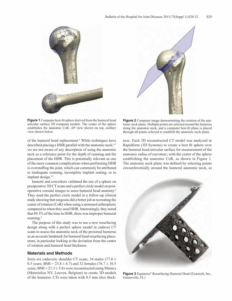
S29Bulletin of the Hospital for Joint Diseases 2015;73(Suppl 1):S28-32
of the humeral head replacement.6 While techniques have described placing a HHR parallel with the anatomic neck,6,7 we are not aware of any description of using the anatomic neck as a reference point for the depth of reaming and the placement of the HHR. This is potentially relevant as one of the more common complications when performing HHR is overstuffing the joint, which can commonly be attributed to inadequate reaming, incomplete implant seating, or to implant design.3,5 Iannotti and coworkers validated the use of a sphere on preoperative 3D CT scans and a perfect circle model on post-operative coronal images to asses humeral head anatomy.8 They used the perfect circle model in a follow-up clinical study showing that surgeons did a better job at recreating the center of rotation (CoR) when using a stemmed arthroplasty compared to when they used HHR. Interestingly, they noted that 89.3% of the time in HHR, there was improper humeral reaming.9
The purpose of this study was to use a new resurfacing design along with a perfect sphere model in cadaver CT scans to assess the anatomic neck of the proximal humerus as an accurate landmark for humeral head resurfacing place-ment, in particular looking at the deviation from the center of rotation and humeral head thickness.
Materials and MethodsSixty-six cadaveric shoulder CT scans, 34 males (77.0 ± 8.5 years; BMI = 23.8 ± 6.7) and 32 females (76.7 ± 10.5 years; BMI = 21.3 ± 5.8) were reconstructed using Mimics (Materialise NV, Leuven, Belgium) to create 3D models of the humerus. CTs were taken with 0.5 mm slice thick-
ness. Each 3D reconstructed CT model was analyzed in Rapidform (3D Systems) to create a best fit sphere over the humeral head articular surface for measurement of the anatomic radius of curvature, with the center of the sphere establishing the anatomic CoR, as shown in Figure 1. The anatomic neck plane was defined by selecting points circumferentially around the humeral anatomic neck, as
Figure 1 Computer best-fit sphere derived from the humeral head articular surface 3D computer models. The center of the sphere establishes the anatomic CoR. AP view shown on top, axillary view shown below.
Figure 2 Computer image demonstrating the creation of the ana-tomic neck plane. Multiple points are selected around the humerus along the anatomic neck, and a computer best-fit plane is placed through all points selected to establish the anatomic neck plane.
Figure 3 Equinoxe® Resurfacing Humeral Head (Exactech, Inc., Gainesville, FL)
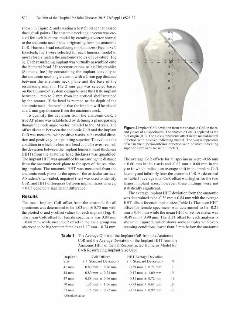
Bulletin of the Hospital for Joint Diseases 2015;73(Suppl 1):S28-32S30
shown in Figure 2, and creating a best fit plane that passed through all points. The anatomic neck angle vector was cre-ated for each humerus model by creating a vector normal to the anatomic neck plane, originating from the anatomic CoR. Humeral head resurfacing implant sizes (Equinoxe®, Exactech, Inc.) were selected for each humeral model to most closely match the anatomic radius of curvature (Fig 3). Each resurfacing implant was virtually assembled onto the humeral head 3D reconstructions using Unigraphics (Siemens, Inc.) by constraining the implant coaxially to the anatomic neck angle vector, with a 2 mm gap distance between the anatomic neck plane and the base of the resurfacing implant. The 2 mm gap was selected based on the Equinoxe® system design to seat the HHR implant between 1 mm to 2 mm from the cortical shelf retained by the reamer. If the head is reamed to the depth of the anatomic neck, the result is that the implant will be placed at a 2 mm gap distance from the anatomic neck. To quantify the deviation from the anatomic CoR, a true AP plane was established by defining a plane passing though the neck angle vector, parallel to the IM axis. The offset distance between the anatomic CoR and the implant CoR was measured with positive x-axis in the medial direc-tion and positive y-axis pointing superior. To evaluate the condition in which the humeral head could be over-reamed, the deviation between the implant humeral head thickness (HHT) from the anatomic head thickness was quantified. The implant HHT was quantified by measuring the distance from the anatomic neck plane to the apex of the resurfac-ing implant. The anatomic HHT was measured from the anatomic neck plane to the apex of the articular surface. A Student’s two-tailed, unpaired t-test was used to identify CoR, and HHT differences between implant sizes where p < 0.05 denoted a significant difference.
ResultsThe mean implant CoR offset from the anatomic for all specimens was determined to be 1.03 mm ± 0.75 mm with the plotted x- and y- offset values for each implant (Fig. 4). The mean CoR offset for female specimens was 0.84 mm ± 0.68 mm, while mean CoR offset in the male group was observed to be higher than females at 1.17 mm ± 0.74 mm.
The average CoR offsets for all specimens were -0.66 mm ± 0.60 mm in the x-axis and -0.62 mm ± 0.60 mm in the y-axis, which indicate an average shift in the implant CoR laterally and inferiorly from the anatomic CoR. As described in Table 1, average total CoR offset was higher for the two largest implant sizes; however, these findings were not statistically significant. The average implant HHT deviation from the anatomic was determined to be -0.36 mm ± 0.84 mm with the average HHT offsets for each implant size (Table 1). The mean HHT offset for female specimens was determined to be -0.21 mm ± 0.76 mm while the mean HHT offset for males was -0.49 mm ± 0.90 mm. The HHT offset for each analysis is shown in Figure 5, which shows some samples with over-reaming conditions lower than 2 mm below the anatomic
Table 1 The Average Offset of the Implant CoR from the Anatomic CoR and the Average Deviation of the Implant HHT from the Anatomic HHT of the 3D Reconstructed Humerus Model for Each Resurfacing Implant Size Used
Implant Size
CoR Offset*( ± Standard Deviation)
HHT Average Deviation( ± Standard Deviation) N
41 mm 0.89 mm ± 0.76 mm -0.39 mm ± 0.71 mm 744 mm 0.89 mm ± 0.73 mm -0.17 mm ± 1.00 mm 947 mm 0.88 mm ± 0.66 mm -0.31 mm ± 0.72 mm 1950 mm 1.35 mm ± 1.06 mm -0.73 mm ± 0.61 mm 853 mm 1.15 mm ± 0.72 mm -0.33 mm ± 0.99 mm 23*Absolute value.
Figure 4 Implant CoR deviation from the anatomic CoR in the x- and y-axes of all specimens. The anatomic CoR is depicted as the plot origin (0,0). The x-axis represents offset in the medial-lateral direction with positive indicating medial. The y-axis represents offset in the superior-inferior direction with positive indicating superior. Both axes are in millimeters.

S31Bulletin of the Hospital for Joint Diseases 2015;73(Suppl 1):S28-32
HHT. There were no statistically significant differences observed between HHT offsets for each implant size used.
Discussion The results of this study demonstrate that using the anatomic neck as a landmark for depth of reaming allowed for accurate restoration of the anatomic CoR and HHT with humeral head resurfacing. While it has been described to use the anatomic neck as a guide to determine humeral height positioning, in-cluding inclination and version,6,7 to our knowledge it has not been described to use the anatomic neck as the landmark for determining the appropriate depth of the resurfacing implant position. We believe that this could account, at least in part, for some of the reports of joint overstuffing after a resurfac-ing procedure5 and may explain some of the discrepancies found in the literature pertaining to the ability of a HHR to recreate the proximal humeral geometry. The discrepancies may also be implant specific, and our results may also be related to a thinner, more anatomic design. The Equinoxe® resurfacing is a modular implant that utilizes a cannulated system to insert a caged peg into the humeral head allow-ing for bony through-growth and modular assembly to better reconstruct a patient’s anatomy (Fig 3). The humeral prosthesis is only 1.5 mm thick, which is noticeably thin-ner than the traditional 4 mm thick Copeland HHR device. The instrument system is designed so that the HHR implant sits off the remaining cortical shelf formed from the reamer base. By reaming down to the anatomic neck, the implant is automatically placed at a set distance from the anatomic neck when fully seated. Mechlenburg and associates concluded, after evaluat-ing the Length of the Gleno-Humeral Offset (LGHO) on
standardized radiographs, that the Copeland resurfacing increased the postoperative LGHO, and that this overstuff-ing of the joint led to a high revision rate (14%).5 Mansat and colleagues, however, found that HHR did restore the humeral anatomy in their radiographic study,3 and in a computer model of non-arthritic joints, Hammond and coworkers concluded that the HHR more closely restored the geometric center than stemmed hemiarthroplasty when using an Arthrosurface® implant.4
In their clinical study, Alolabi and associates reported that the average deviation of the CoR for HHR was 3.8 mm ± 2.1 mm.9 When using a computer model to identify and place the humeral component, we found that our average deviation was decreased to 1.03 mm ± 0.75 mm. Obviously, some of this improvement can be explained by the ease of identifying and placing the prosthesis virtually in the computer model, as op-posed to identifying the anatomic neck of a deformed humerus intraoperatively and placing a prosthesis based on this. Alolabi and associates stated in their study that finding the anatomic neck in vivo is often difficult and could explain the increased deviation.9 Whether due to difficulty identifying the anatomic neck or failure to ream to the proper depth, they showed that 89.3% of HHR had improper reaming.9 We believe that by us-ing the anatomic neck as a landmark for humeral head reaming and subsequent placement of a new, thinner HHR, we are better able to recreate the proximal humeral anatomy decreasing the deviation of the CoR and HHT. There are several limitations of this study. First, it is a computer model using non-arthritic shoulders. It is much harder to identify the anatomic neck intraoperatively on an arthritic or other deformed shoulder, and future studies will need to evaluate if this technique can be safely and reliably reproduced clinically. Secondly, the use of the anatomic neck as a guide for the reaming depth of the HHR may be design specific, and further studies need to be performed specifically comparing different prosthetic designs placed at the same anatomic location. Although the computer study shows that the HHT can be accurately reproduced, it will need to be determined, clinically, whether or not reaming the humerus to the anatomic neck removes too much subchondral bone to implant a HHR safely. Finally, more clinical studies will need to be performed to evaluate HHR outcomes and whether decreasing the deviation from the CoR improves outcomes.
ConclusionsThis computer model demonstrated that using the anatomic neck as a landmark for the depth of reaming with HHR ac-curately restores the CoR and HHT of the proximal humerus, better than previously reported. Future studies should inves-tigate if this method for HHR placement can be reproduced in situ and if these results improve clinical performance.
Conflict of Interest StatementRyan Simovitch, M.D., Felix Savoie, M.D., and Curtis R. Noel, M.D., are consultants for Exactech, Inc., and receive
Figure 5 Implant HHT deviation from the anatomic HHT, grouped by implant sizes used for each specimen. Positive offset values in-dicate resurfacing implant placement above the anatomic articular surface, and negative offset indicates placement below the native articular surface.

Bulletin of the Hospital for Joint Diseases 2015;73(Suppl 1):S28-32S32
royalties on products related to this article. Emmon J. Chen, M.S., is an employee of Exactech, Inc., Gainesville, Florida.
References
1. Levy O, Copeland SA. Cementless surface replacement ar-throplasty of the shoulder: 10-year results with the Copeland Mark-2 Prosthesis. J Bone Joint Br. 2001 Mar;83(2):213-21.
2. Mullett H, Levy O, Raj D, et al. Copeland surface replace-ment of the shoulder. Results of an hydroxyapatite-coated cementless implant in patients over 80 years of age. J Bone Joint Surg Br. 2007 Nov;89(11):1466-9.
3. Mansat P, Coutie AS, Bonevaile N, et al. Resurfacing humeral prosthesis: do we really reconstruct the anatomy? J Shoulder Elbow Surg. 2013 May;22(5):612-9.
4. Hammond G, Tibbone JE, McGarry MH, et al. Biomechani-cal comparison of anatomic humeral head resurfacing and hemiarthroplasty in functional glenohumeral positions. J Bone Joint Surg Am. 2012 Jan 4;94(1):68-76.
5. Mechlenburg I, Amstrup A, Klebe T, et al. The Copeland resurfacing humeral head implant does not restore humeral head anatomy. A retrospective study. Arch Orthop Trauma Surg. 2013 May;133(5):615-9.
6. Thomas SR, Sforza G, Levy O, Copeland SA. Geometrical analysis of Copeland surface replacement shoulder arthro-plasty in relation to normal anatomy. J Shoulder Elbow Surg. 2005 Mar-Apr;14(2):186-92.
7. Jensen KL. Humeral resurfacing arthroplasty: Rationale, indications, technique, and results. Am J Orthop(Belle Mead NJ). 2007 Dec;36(12 Suppl 1):4-8.
8. Youderian AR, Ricchetti ET, Drews M, Iannotti JP. Determina-tion of humeral head size in anatomic shoulder replacement for glenohumeral osteoarthritis. J Shoulder Elbow Surg. 2014 Jul;23(7):955-63.
9. Alolabi B, Youderian AR, Napolitano L, et al. Radiographic assessment of prosthetic humeral head size after ana-tomic shoulder arthroplasty. J Shoulder Elbow Surg. 2014 Nov;23(11):1740-6.

S33Bulletin of the Hospital for Joint Diseases 2015;73(Suppl 1):S33-6
Becks L, Gaydos C, Stroud N, Roche CP. Optimization of cemented glenoid peg geometry: a comparison of resistance to axial distraction. Bull Hosp Jt Dis. 2015;73(Suppl 1):S33-6.
Abstract
Introduction: Glenoid loosening is one of the most com-mon complications of anatomic total shoulder arthroplasty (aTSA). Numerous glenoid pegged designs exist within the market place; however, little effort has been made to optimize peg geometry, and as a result, there is no consensus regard-ing the superiority of one design over another. The aim of this study was to determine the impact of peg design on the fixation strength by comparing the force and displacement associated with five different geometries of cemented glenoid components when each is axially displaced from two differ-ent densities of polyurethane bone substitute substrates. Methods: An axial pull-out test was conducted on five different cemented peg geometries in both low- and high-density polyurethane bone-substitute blocks. All substrates were prepared utilizing a drill, which created a 7.3 mm diameter hole to a depth of 26.8 mm. Cemex® brand bone cement was prepared and used to cement all pegs. After cementation of each peg, an electromechanical load frame applied a linear ramp displacement of 10 mm/minute axially to each peg while the polyurethane block was fully con-strained. Load and displacement of each peg was sampled at 100 Hz until failure and axial distraction of each peg where the peak pull-out force and associated displacement were recorded. The average load to failure and associated displacement for each peg geometry were compared utiliz-ing the Student’s t-test where a p-value < 0.05 determined significance.
Results: Cemented peg design #3 was associated with the greatest axial load to failure (675.3 N ± 18.8 N in low density and 707.3 N ± 11.7 N in high density) for both densities of bone-substitute blocks. Peg designs #5 and #2 were associated with the next highest axial loads to failure in both low and high density blocks. Finally, peg designs #1 and #4 were associated with the lowest axial loads to failure in both low and high density blocks. Only design #3 had a statistically significant difference between peak pull-out forces between the low- and high-density bone substitute blocks, as compared to all other designs. Conclusions: The results of this study demonstrate that glenoid peg geometry can significantly influence the resis-tance to axial distraction where the continuous threaded geometry exemplified by peg design #3 demonstrated sig-nificantly superior cemented fixation relative to the other peg designs. It can be concluded that overall macrostructure and design of the peg itself plays a key role in pull-out force; however, performance in a clinical setting is required to confirm these biomechanical results.
Glenoid loosening is one of the most common complications of total shoulder arthroplasty and is considered to be the limiting long-term failure
mode. The causes of loosening are multi-factorial and include off-center or rim loading, called “rocking horse phenomenon,” constrained prosthetic systems that induce too great a torque on the fixation surfaces, poor implanta-tion technique, use in eroded or compromised scapula, and poor cementation technique.1-3 There are two typical designs of glenoid components, namely keel or peg. Keel designs, as compared to peg designs, require more bone resection and also more cement and have been associ-ated with increased rotation and translation,4 as well as increased radiolucent lines.5 Peg glenoids remove less bone and typically require less cement. Numerous glenoid
Optimization of Cemented Glenoid Peg GeometryA Comparison of Resistance to Axial Distraction
Lisa Becks, M.S., Corey Gaydos, B.S., Nicholas Stroud, M.S., and Christopher P. Roche, M.S., M.B.A.
Lisa Becks, M.S., Corey Gaydos, B.S., Nicholas Stroud, M.S., and Christopher P. Roche, M.S., M.B.A., Exactech, Inc., Gainesville, Florida. Correspondence: Christopher P. Roche, M.S., M.B.A., Exactech, Inc., 2320 NW 66th Court, Gainesville, Florida 32653; [email protected].

Bulletin of the Hospital for Joint Diseases 2015;73(Suppl 1):S33-6S34
pegged designs exist within the market place; however, little effort has been made to optimize peg geometry, and as a result, there is no consensus regarding the superior-ity of one design over another. The aim of this study is to determine the impact of peg design on the fixation strength by comparing the force and displacement associated with five different geometries of cemented glenoid components when each is axially displaced from two different densities of polyurethane bone substitute substrates.
Materials and MethodsFive unique center peg geometries (Fig. 1) were designed in a 3D computer modeling software (Unigraphics NX, Siemens, Inc.). Each peg design was manufactured from GUR 1050 Ultra High Molecular Weight Polyethylene (UHMWPE) with an equivalent surface finish in order to test cement fixa-tion by axial distraction. All devices were vacuum packaged and gamma-sterilized to a maximum dosage of 37 kGy. Peg designs #1 and #4 were intended to simulate the geometry of FDA-cleared cemented devices with more than 10 years of clinical experience, whereas peg designs #2, #3, and #5 were novel and were intended to maximize cement mantle thickness and uniformity. All pegs were 13.5 mm in length except for design #1, which was only 12 mm long. Similarly, all designs utilized a 7° taper except for design #4, which was cylindrical. Eight samples of each peg geometry were assembled in both low- or high-density polyurethane bone substitute (15 pcf and 30 pcf, respectively) blocks [conform-ing to ASTM F1839-08(2012) to simulate poor and good quality bone] for a total of 80 tested samples. Both the low and high density blocks were prepared utilizing a drill creating a 7.3 mm diameter hole to a depth of 26.8 mm. Cemex® brand bone cement (Tecres, Inc., Verona, Italy) was used to cement all pegs. After cementa-tion of each peg to the substrate, an electromechanical load frame applied a linear ramp displacement of 10 mm/minute axially to each peg while the polyurethane block was fully constrained (Fig. 2). To ensure that each test sample was loaded axially, a universal joint was used to link the sample to the test frame. Load and displacement of each peg were sampled at 100 Hz until failure or axial distraction of each peg. The average load to failure and associated displacement for each peg geometry were recorded and compared utiliz-
ing the Student’s unpaired, two-tailed t-test, where p-value < 0.05 determined significance.
ResultsThe average axial force required to extract each peg design in both the low and high density polyurethane blocks is described in Figure 3. Numerous differences were noted in the peak pull-out forces between designs and substrate densities (Table 1). Peg design #3 was associated with the greatest axial load to failure (675.3 N ± 18.8 N in low density and 707.3 N ± 11.7 N in high density) for both densities of bone-substitute blocks. Peg designs #5 and #2, respectively, were associated with the next highest axial loads to failure in both low and high density blocks. Finally, peg designs #4 and #1 were associated with the lowest axial loads to failure in both low and high density blocks. Failure modalities between peg designs were similar
Figure 1 Five different types of peg geometries tested.
Figure 2 Photograph of the test setup immediately after completing axial pull out testing of one of the peg design samples.

S35Bulletin of the Hospital for Joint Diseases 2015;73(Suppl 1):S33-6
for the high density blocks (in which the peg disassociated from the cement in all cases) but different for the low den-sity blocks, where in some cases the substrate failed prior to the peg disassociating from the cement. Six of the eight tested pegs of peg design #3 failed in the low density block by the substrate fracturing before the peg disassociated from the cement. It should be noted that only four samples of peg design #4 were able to be evaluated in high-density foam due to poor assembly: two of these samples were able to be removed with the force of gravity, and the other two samples had been deformed during assembly such that they could not be attached to the end of the load frame; thus, these samples were excluded from the results. Plastic
deformation was observed to some extent on all samples during axial extraction. The average displacement to peak pull-out force for each peg geometry is presented in Figure 4. Differences in mean displacement at peak pull-out force were observed between designs and substrate densities, (Table 2) where design #5 was associated with the lowest displacement.
DiscussionGiven the growth of total shoulder arthroplasty over the last decade, the uniformity of belief that the cemented peg glenoid is the gold-standard, and persistent concerns about the complication of aseptic glenoid loosening as the long-
Table 1 The Results of the Statistical Analysis are Provided in the Form of P-values Found when Comparing the Mean Peak Pull-Out Force for Each of the Tested Peg Geometries
Design 1 Design 2 Design 3 Design 4 Design 5Design 1 < 0.0001 < 0.0001 0.0002 < 0.0001
High DensityDesign 2 < 0.0001 < 0.0001 0.0013 0.0027Design 3 < 0.0001 < 0.0001 < 0.0001 < 0.0001Design 4 0.2878 0.0002 < 0.0001 < 0.0001Design 5 < 0.0001 0.0120 < 0.0001 < 0.0001
Low Density
Table 2 The Results of the Statistical Analysis are Provided in the Form of P-values Found when Comparing the Mean Displacement at Peak Pull-Out Force for Each of the Tested Peg Geometries
Design 1 Design 2 Design 3 Design 4 Design 5Design 1 0.0002 0.9350 0.0010 < 0.0001
High-Density
Design 2 0.0004 0.0790 0.1150 < 0.0001Design 3 0.1130 0.0010 0.0510 0.1280Design 4 0.2160 0.0070 0.9420 < 0.0001Design 5 < 0.0001 < 0.0001 0.3260 0.3690
Low-Density
Figure 3 Average peak pull-out force for each test group in low- and high-density bone. The error bars represent one standard deviation.
Figure 4 Average load displacement curves at peak pull-out force for each test group in low- and high-density bone. The error bars represent one standard deviation.
Bulletin of the Hospital for Joint Diseases 2015;73(Suppl 1):S33-6S36
term failure mode, it is important that more effort be made to optimize the design of the cemented peg glenoid. Anglin and others have evaluated different design parameters over 15 years ago—but little work has been done since to further refine and optimize the design of the cemented peg glenoid.6 This current study evaluates the impact of two commercially successful cemented center peg designs, each with over 10 years clinical experience and compares the cemented fixation in both low and high density bone blocks to that of three novel peg geometries that facilitates a more uniform and thicker cement mantle over the length of the peg. The average peak pull-out results of this study objec-tively demonstrated that peg geometry #3 provided superior resistance to axial extraction in both low and high density bone-substitute blocks as compared to the other four designs evaluated; however, the displacement at the peak pull-out forces were minimally different between peg designs. The exact reasons for the superior results of design #3 are un-clear; however, we suspect that the thicker helical thread form permitted greater flow of the cement around the peg while the larger outer diameter along the length of the peg created greater cement pressurization. Several recent stud-ies in the literature have demonstrated that greater cement pressurization results in a reduction of the incidence of radiolucent lines clinically.7,8 It may be that a peg geometry, such as utilized in design #3, is able to achieve pressurization without the need for supplemental pressurization instrumen-tation. This study has several limitations. We utilized a poly-urethane bone-substitute block of two different densities to simulate both good and poor quality bone rather than actual cadaveric bone for reasons of cost and concerns of unifor-mity in bone quality across all test samples. Improvements to this test could also include the use of a composite substrate to simulate cortical and cancellous bone. Additionally, this test strictly quantified the impact of different peg geom-etries on axial pull-out strength; we fully recognize that this axial-loading methodology is non-physiological and does not simulate the clinical failure mechanism as described by the rocking horse phenomenon.6 However, as translational movements of the humeral head on the glenoid component occur during glenohumeral movement, a greater pull-out strength of the fixation pegs can be beneficial for stability of the component.9 Future work should evaluate the impact of different ce-ment viscosities and also different thicknesses of cement mantle by the use of different diameters of drills on cemented peg fixation. Additionally, as these results objectively dem-onstrate that the axial resistance of cemented peg design #3 is superior to the other devices tested, future work should evaluate the combined application of this peg geometry on both central and peripheral pegs. Finally, additional testing to qualify this peg geometry is required to confirm sufficient
resistance to the applied torque resulting from eccentric hu-meral head edge loading by the rocking-horse phenomenon.6
ConclusionThe results of this study demonstrate that glenoid peg geom-etry can significantly influence the resistance to axial distrac-tion, where the continuous threaded geometry exemplified by peg design #3 demonstrated superior cemented fixation relative to the other peg designs tested in this study. It can therefore be concluded that overall macrostructure and design of the peg itself plays a key role in pull-out force of cemented UHMPWE pegs. While the clinical application of this novel peg geometry appears promising based upon the results of this biomechanical study, these laboratory results are not a substitute for clinical performance. Ultimately, long-term clinical follow-up is necessary to demonstrate glenoid design optimization through the reduced incidence of radiolucent lines and aseptic glenoid loosening as a complication.
Conflict of Interest StatementFunding for this study was provided by Exactech, Inc. Lisa Becks, M.S., Corey Gaydos, B.S., Nicholas Stroud, M.S., and Christopher P. Roche, M.S., M.B.A., are employees of Exactech, Inc., Gainesville, Florida
References1. Franklin JL, Barrett WP, Jackins SE, Matsen FA III. Glenoid
loosening in total shoulder arthroplasty: association with rotator cuff deficiency. J Arthroplasty. 1988;3(1):39-46.
2. Post M. Constrained arthroplasty of the shoulder. Orthop Clin North Am. 1987 Jul;18(3):455-62.
3. Norris BL, Lachiewicz PF. Modern cement technique and the survivor-ship of total shoulder arthroplasty. Clin Orthop 1996 Jul;(328):76-85.
4. Nuttall D, Haines JF, Trial II. A study of the micromovement of pegged and keeled glenoid components compared using radiostereometric analysis. J Shoulder Elbow Surg 2007 May-Jun;16(3 suppl); S65-70.
5. Gartsman GM, Elkousy HA, Warnock KM, et al. Radiographic comparison of pegged and keeled glenoid components. J Shoulder Elbow Surg. 2005 May-Jun;14(3):252-7.
6. Anglin C, Wyss UP, Pichora DR. Mechanical testing of shoulder prostheses and recommendations for glenoid design. J Shoulder Elbow Surg. 2000 Jul-Aug;9(4):323-31.
7. Choi T, Horodyski M, Struk A, et al. Incidence of early radiolucent lines after glenoid component insertion for total shoulder arthroplasty: a radiographic study comparing pres-surized and unpressurized cementing techniques. J Shoulder Elbow Surg. 2013 Mar;22(3):403-8.
8. Raiss P, Sowa B, Bruckner T, et al. Pressurisation leads to better cement penetration into the glenoid bone. J Bone Joint Surg Br. 2012 May;94(5):671-7.
9. Nyffeler RW, Anglin C, Sheikh R, Gerber C. Influence of peg design and cement mantle thickness on pull-out strength of glenoid component pegs. J Bone Joint Surg Br. 2003 Jul;85(5):748-52.
S37Bulletin of the Hospital for Joint Diseases 2015;73(Suppl 1):S37-41
Roche CP, Hamilton MA, Diep P, Wright TW, Flurin P-H, Zuckerman JD, Routman HD. Optimizing deltoid efficiency with reverse shoulder arthro-plasty using a novel inset center of rotation glenosphere design. Bull Hosp Jt Dis. 2015;73(Suppl 1):S37-41.
Abstract
Introduction: Paul Grammont’s hemispherical gleno-sphere concept medializes the center of rotation (CoR) to the glenoid face to increase deltoid abductor moment arms and improve muscle efficiency. Reducing glenosphere thickness to less than half its spherical radius further medializes the CoR and offers the potential for even greater improvements in efficiency. To that end, this study quantifies deltoid abduc-tor moment arms for six different rTSA prostheses during scapular abduction from 0° to 140°. Methods: A 3D computer model was developed in Uni-graphics to quantify deltoid moment arms during scapular abduction for the normal anatomic shoulder, the 36 mm Grammont Delta III (Depuy, Inc.), 36 mm BIO-RSA® (Tornier, Inc.), the 32 mm RSP® (DJO, Inc.), and the Equi-noxe® rTSA (Exactech, Inc.) with three different glenosphere geometries: 38 mm x 21 mm, 46 mm x 25 mm, and the novel 46 mm x 21 mm. Each muscle was simulated as three lines from origin to insertion as the arm was elevated; positional data was exported to Matlab where the abductor moment arms were calculated for the anterior, middle, and posterior deltoid from 0° to 140° humeral abduction in the scapular plane using a 1.8:1 scapular rhythm.
Results: The 46 mm x 21 mm glenosphere had the larg-est average abductor moment arms and also the largest efficiency for all three heads of the deltoid, having a 4.8% to 40.7% increase in the average deltoid efficiency relative to all other designs tested. The glenosphere design with the next most efficient deltoid was the 36 mm Delta III, which had the next most medialized CoR. The two least efficient designs were the BIO-RSA® and the DJO RSP®, which had the most lateral CoR. Discussion: These results provide new biomechanical insights on the impact of glenosphere geometry on deltoid abductor moment arms and demonstrate that subtle changes in rTSA prosthesis design can result in dramatic improve-ments. Increasing glenosphere diameter while also decreas-ing thickness to be less than half its spherical radius may minimize the muscle forces required to perform activities of daily living. Clinical follow-up is necessary to demonstrate a reduction in complications related to joint over-loading and also demonstrate greater increases in range of motion for patients with weak musculature.
Much of the recent clinical and commercial success associated with reverse total shoulder arthroplasty (rTSA) can be attributed to Paul Grammont’s in-
novations in shoulder prosthesis design. In 1991, Grammont first recommended a glenosphere geometry in which the thickness was one-half its diameter to position the center of rotation (CoR) directly on the glenoid face in order to reduce torque on the glenoid fixation interface while also increasing the deltoid abductor moment arms in order to improve deltoid efficiency.1 This hemispherical glenosphere concept has been the geometric predicate for nearly every rTSA prosthesis released in the global marketplace since that time. The primary design variation in glenosphere geometry has been to increase the thickness relative to the spherical radius in order to lateralize the CoR and also lateralize the
Optimizing Deltoid Efficiency with Reverse Shoulder Arthroplasty Using a Novel Inset Center of Rotation Glenosphere Design
Christopher P. Roche, M.S., M.B.A., Matthew A. Hamilton, Ph.D., Phong Diep, B.S., Thomas W. Wright, M.D., Pierre-Henri Flurin, M.D., Joseph D. Zuckerman, M.D., and Howard D. Routman, D.O.
Christopher P. Roche, M.S., M.B.A., Matthew A. Hamilton, Ph.D., Phong Diep, B.S., Exactech, Inc., Gainesville, Florida. Thomas W. Wright, M.D., Department of Orthopaedics and Rehabilitation, University of Florida, Gainesville, Florida. Pierre-Henri Flurin, M.D., Bordeaux-Merignac Clinique du Sport, Merignac, France. Joseph D. Zuckerman, M.D., Department of Orthopaedic Surgery, Hospital for Joint Diseases, NYU Langone Medical Center, New York, New York. Howard D. Routman, D.O., Atlantis Orthopaedics, Palm Beach Gardens, Florida.Correspondence: Christopher P. Roche, M.S., M.B.A., Exactech, Inc., 2320 NW 66th Court, Gainesville, Florida 32653; [email protected].
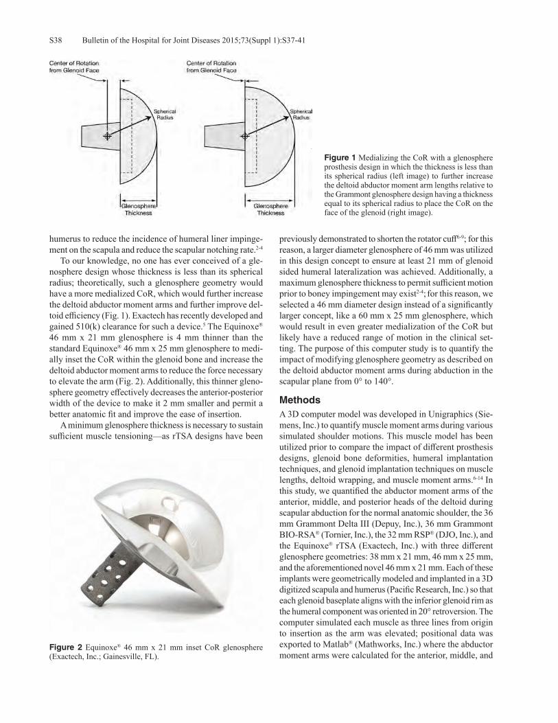
Bulletin of the Hospital for Joint Diseases 2015;73(Suppl 1):S37-41S38
humerus to reduce the incidence of humeral liner impinge-ment on the scapula and reduce the scapular notching rate.2-4 To our knowledge, no one has ever conceived of a gle-nosphere design whose thickness is less than its spherical radius; theoretically, such a glenosphere geometry would have a more medialized CoR, which would further increase the deltoid abductor moment arms and further improve del-toid efficiency (Fig. 1). Exactech has recently developed and gained 510(k) clearance for such a device.5 The Equinoxe® 46 mm x 21 mm glenosphere is 4 mm thinner than the standard Equinoxe® 46 mm x 25 mm glenosphere to medi-ally inset the CoR within the glenoid bone and increase the deltoid abductor moment arms to reduce the force necessary to elevate the arm (Fig. 2). Additionally, this thinner gleno-sphere geometry effectively decreases the anterior-posterior width of the device to make it 2 mm smaller and permit a better anatomic fit and improve the ease of insertion. A minimum glenosphere thickness is necessary to sustain sufficient muscle tensioning—as rTSA designs have been
previously demonstrated to shorten the rotator cuff6-9; for this reason, a larger diameter glenosphere of 46 mm was utilized in this design concept to ensure at least 21 mm of glenoid sided humeral lateralization was achieved. Additionally, a maximum glenosphere thickness to permit sufficient motion prior to boney impingement may exist2-4; for this reason, we selected a 46 mm diameter design instead of a significantly larger concept, like a 60 mm x 25 mm glenosphere, which would result in even greater medialization of the CoR but likely have a reduced range of motion in the clinical set-ting. The purpose of this computer study is to quantify the impact of modifying glenosphere geometry as described on the deltoid abductor moment arms during abduction in the scapular plane from 0° to 140°.
MethodsA 3D computer model was developed in Unigraphics (Sie-mens, Inc.) to quantify muscle moment arms during various simulated shoulder motions. This muscle model has been utilized prior to compare the impact of different prosthesis designs, glenoid bone deformities, humeral implantation techniques, and glenoid implantation techniques on muscle lengths, deltoid wrapping, and muscle moment arms.6-14 In this study, we quantified the abductor moment arms of the anterior, middle, and posterior heads of the deltoid during scapular abduction for the normal anatomic shoulder, the 36 mm Grammont Delta III (Depuy, Inc.), 36 mm Grammont BIO-RSA® (Tornier, Inc.), the 32 mm RSP® (DJO, Inc.), and the Equinoxe® rTSA (Exactech, Inc.) with three different glenosphere geometries: 38 mm x 21 mm, 46 mm x 25 mm, and the aforementioned novel 46 mm x 21 mm. Each of these implants were geometrically modeled and implanted in a 3D digitized scapula and humerus (Pacific Research, Inc.) so that each glenoid baseplate aligns with the inferior glenoid rim as the humeral component was oriented in 20° retroversion. The computer simulated each muscle as three lines from origin to insertion as the arm was elevated; positional data was exported to Matlab® (Mathworks, Inc.) where the abductor moment arms were calculated for the anterior, middle, and
Figure 1 Medializing the CoR with a glenosphere prosthesis design in which the thickness is less than its spherical radius (left image) to further increase the deltoid abductor moment arm lengths relative to the Grammont glenosphere design having a thickness equal to its spherical radius to place the CoR on the face of the glenoid (right image).
Figure 2 Equinoxe® 46 mm x 21 mm inset CoR glenosphere (Exactech, Inc.; Gainesville, FL).

S39Bulletin of the Hospital for Joint Diseases 2015;73(Suppl 1):S37-41
posterior deltoid from 0° to 140° humeral abduction in the scapular plane using a 1.8:1 scapular rhythm.
Results The abductor moment arms for the anterior, middle, and posterior heads of the deltoid for each glenosphere geometry and the normal anatomic shoulder during scapular abduc-tion from 0° to 140° are presented in Figures 3, 4, and 5,
respectively. The average increase in the abductor muscle moment arms relative to the normal anatomic shoulder for each glenosphere geometry is termed deltoid efficiency and is presented in Table 1. As described in these Figures and Table 1, the 46 x 21 mm glenosphere was associated with the largest average abductor moment arms and also the largest efficiency for all three heads of the deltoid with the greatest increases at low to mid ranges of elevation. Specifically, the 46 x 21 mm glenosphere was associated with a 4.8% to 40.7% increase in the average deltoid efficiency relative to all of the other glenosphere designs tested. The glenosphere design with the next most efficient deltoid was the 36 mm Grammont Delta III, which had the next most medialized CoR. The use of 10 mm of bone graft behind the baseplate with the BIO-RSA® technique made this device significantly less efficient, resulting in a 29.4% decrease in anterior deltoid efficiency, 30.2% decrease in middle deltoid efficiency, and a 28.7% decrease in posterior deltoid efficiency. As expected, the 32 mm DJO RSP® device with the most lateral CoR position was the least efficient of all rTSA designs tested.
DiscussionThe results of this study demonstrate that a wide range of de-sign variability exists in the glenoid component with rTSA and
Figure 4 Comparison of middle deltoid moment arms during scapular abduction from 0° to 140°.
Figure 5 Comparison of posterior deltoid moment arms during scapular abduction from 0° to 140°.
Figure 3 Comparison of anterior deltoid moment arms during scapular abduction from 0° to 140°.
Table 1 Average Increase in Deltoid Abductor Moment Arms Relative to the Normal Anatomic Shoulder during Scapular Abduction from 0° to 140°
Average Deltoid Efficiency% Decrease in Abductor Moment Arm Efficiency
Relative to the 46 mm Inset CoR GlenosphereAnt Deltoid Middle Deltoid Post Deltoid Ant Deltoid Middle Deltoid Post Deltoid
36 mm Grammont Delta III 124.2% 122.1% 121.7% 10.2% 4.8% 10.5%36 mm Grammont BIO-RSA® 94.8% 91.9% 93.1% 39.7% 35.1% 39.2%32 mm DJO RSP® 93.7% 89.1% 91.6% 40.7% 37.8% 40.7%38 mm Equinoxe® 116.7% 110.8% 114.8% 16.7% 16.2% 17.5%46 mm Equinoxe® 119.9% 112.7% 117.3% 14.5% 14.3% 15.0%46 mm Inset CoR Equinoxe® 134.4% 126.9% 132.3% NA NA NA
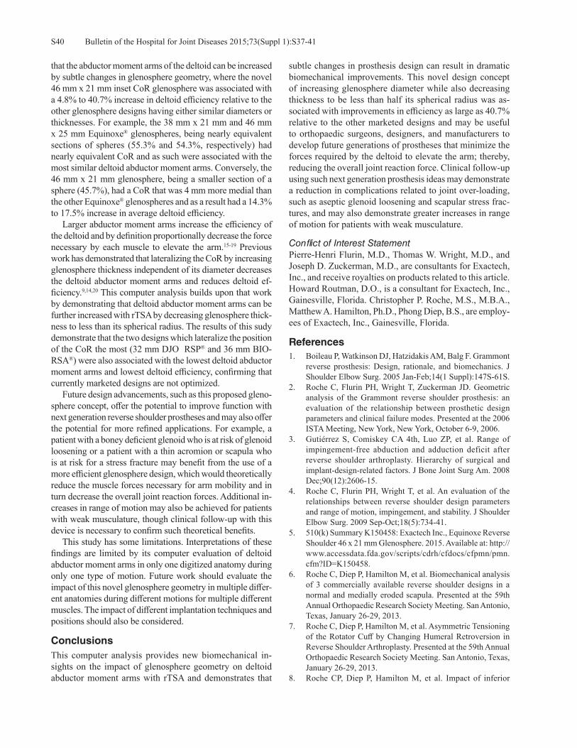
Bulletin of the Hospital for Joint Diseases 2015;73(Suppl 1):S37-41S40
that the abductor moment arms of the deltoid can be increased by subtle changes in glenosphere geometry, where the novel 46 mm x 21 mm inset CoR glenosphere was associated with a 4.8% to 40.7% increase in deltoid efficiency relative to the other glenosphere designs having either similar diameters or thicknesses. For example, the 38 mm x 21 mm and 46 mm x 25 mm Equinoxe® glenospheres, being nearly equivalent sections of spheres (55.3% and 54.3%, respectively) had nearly equivalent CoR and as such were associated with the most similar deltoid abductor moment arms. Conversely, the 46 mm x 21 mm glenosphere, being a smaller section of a sphere (45.7%), had a CoR that was 4 mm more medial than the other Equinoxe® glenospheres and as a result had a 14.3% to 17.5% increase in average deltoid efficiency. Larger abductor moment arms increase the efficiency of the deltoid and by definition proportionally decrease the force necessary by each muscle to elevate the arm.15-19 Previous work has demonstrated that lateralizing the CoR by increasing glenosphere thickness independent of its diameter decreases the deltoid abductor moment arms and reduces deltoid ef-ficiency.9,14,20 This computer analysis builds upon that work by demonstrating that deltoid abductor moment arms can be further increased with rTSA by decreasing glenosphere thick-ness to less than its spherical radius. The results of this sudy demonstrate that the two designs which lateralize the position of the CoR the most (32 mm DJO RSP® and 36 mm BIO-RSA®) were also associated with the lowest deltoid abductor moment arms and lowest deltoid efficiency, confirming that currently marketed designs are not optimized. Future design advancements, such as this proposed gleno-sphere concept, offer the potential to improve function with next generation reverse shoulder prostheses and may also offer the potential for more refined applications. For example, a patient with a boney deficient glenoid who is at risk of glenoid loosening or a patient with a thin acromion or scapula who is at risk for a stress fracture may benefit from the use of a more efficient glenosphere design, which would theoretically reduce the muscle forces necessary for arm mobility and in turn decrease the overall joint reaction forces. Additional in-creases in range of motion may also be achieved for patients with weak musculature, though clinical follow-up with this device is necessary to confirm such theoretical benefits. This study has some limitations. Interpretations of these findings are limited by its computer evaluation of deltoid abductor moment arms in only one digitized anatomy during only one type of motion. Future work should evaluate the impact of this novel glenosphere geometry in multiple differ-ent anatomies during different motions for multiple different muscles. The impact of different implantation techniques and positions should also be considered.
ConclusionsThis computer analysis provides new biomechanical in-sights on the impact of glenosphere geometry on deltoid abductor moment arms with rTSA and demonstrates that
subtle changes in prosthesis design can result in dramatic biomechanical improvements. This novel design concept of increasing glenosphere diameter while also decreasing thickness to be less than half its spherical radius was as-sociated with improvements in efficiency as large as 40.7% relative to the other marketed designs and may be useful to orthopaedic surgeons, designers, and manufacturers to develop future generations of prostheses that minimize the forces required by the deltoid to elevate the arm; thereby, reducing the overall joint reaction force. Clinical follow-up using such next generation prosthesis ideas may demonstrate a reduction in complications related to joint over-loading, such as aseptic glenoid loosening and scapular stress frac-tures, and may also demonstrate greater increases in range of motion for patients with weak musculature.
Conflict of Interest StatementPierre-Henri Flurin, M.D., Thomas W. Wright, M.D., and Joseph D. Zuckerman, M.D., are consultants for Exactech, Inc., and receive royalties on products related to this article. Howard Routman, D.O., is a consultant for Exactech, Inc., Gainesville, Florida. Christopher P. Roche, M.S., M.B.A., Matthew A. Hamilton, Ph.D., Phong Diep, B.S., are employ-ees of Exactech, Inc., Gainesville, Florida.
References 1. Boileau P, Watkinson DJ, Hatzidakis AM, Balg F. Grammont
reverse prosthesis: Design, rationale, and biomechanics. J Shoulder Elbow Surg. 2005 Jan-Feb;14(1 Suppl):147S-61S.
2. Roche C, Flurin PH, Wright T, Zuckerman JD. Geometric analysis of the Grammont reverse shoulder prosthesis: an evaluation of the relationship between prosthetic design parameters and clinical failure modes. Presented at the 2006 ISTA Meeting, New York, New York, October 6-9, 2006.
3. Gutiérrez S, Comiskey CA 4th, Luo ZP, et al. Range of impingement-free abduction and adduction deficit after reverse shoulder arthroplasty. Hierarchy of surgical and implant-design-related factors. J Bone Joint Surg Am. 2008 Dec;90(12):2606-15.
4. Roche C, Flurin PH, Wright T, et al. An evaluation of the relationships between reverse shoulder design parameters and range of motion, impingement, and stability. J Shoulder Elbow Surg. 2009 Sep-Oct;18(5):734-41.
5. 510(k) Summary K150458: Exactech Inc., Equinoxe Reverse Shoulder 46 x 21 mm Glenosphere. 2015. Available at: http://www.accessdata.fda.gov/scripts/cdrh/cfdocs/cfpmn/pmn.cfm?ID=K150458.
6. Roche C, Diep P, Hamilton M, et al. Biomechanical analysis of 3 commercially available reverse shoulder designs in a normal and medially eroded scapula. Presented at the 59th Annual Orthopaedic Research Society Meeting. San Antonio, Texas, January 26-29, 2013.
7. Roche C, Diep P, Hamilton M, et al. Asymmetric Tensioning of the Rotator Cuff by Changing Humeral Retroversion in Reverse Shoulder Arthroplasty. Presented at the 59th Annual Orthopaedic Research Society Meeting. San Antonio, Texas, January 26-29, 2013.
8. Roche CP, Diep P, Hamilton M, et al. Impact of inferior

S41Bulletin of the Hospital for Joint Diseases 2015;73(Suppl 1):S37-41
glenoid tilt, humeral retroversion, bone grafting, and de-sign parameters on muscle length and deltoid wrapping in reverse shoulder arthroplasty. Bull Hosp Jt Dis (2013). 2013;71(4):284-93.
9. Hamilton MA, Roche CP, Diep P, et al. Effect of prosthesis design on muscle length and moment arms in reverse total shoulder arthroplasty. Bull Hosp Jt Dis (2013). 2013;71 Suppl 2:S31-5.
10. Hamilton M, Diep P, Roche C, et al. The effect of reverse shoulder design on the moment arms of muscles surrounding the joint during external rotation. Presented at the 59th Annual Orthopaedic Research Society Meeting. San Antonio, Texas, January 26-29, 2013.
11. Hamilton M, Diep P, Roche C, et al. How does reverse shoul-der design affect rotator muscle moment arms? Presented at the 8th Combined Meeting of the Orthopaedic Research Societies, Venice, Italy, October 13-16, 2013.
12. Hamilton M, Diep P, Roche C, et al. The effect of muscle wrapping on modeling of reverse shoulders. Presented at the 8th Combined Meeting of the Orthopaedic Research Societies, Venice, Italy, October 13-16, 2013.
13. Roche CP, Hamilton MA, Diep P, et al. Design rationale for a posterior/superior offset reverse shoulder prosthesis. Bull Hosp Jt Dis (2013). 2013;71 Suppl 2:S18-24.
14. Hamilton MA, Diep P, Roche C, et al. Effect of reverse shoul-
der design philosophy on muscle moment arms. J Orthop Res. 2015 Apr;33(4):605-13.
15. Otis JC, Jiang CC, Wickiewicz TL, et al. Changes in the mo-ment arms of the rotator cuff and deltoid muscles with abduc-tion and rotation. J Bone Joint Surg Am. 1994 May;76(5):667-76.
16. Kontaxis A, Johnson GR. The biomechanics of reverse anatomy shoulder replacement – a modeling study. Clin Biomech (Bristol, Avon). 2009 Mar;24(3):254-60.
17. Terrier A, Reist A, Merlini F, Farron A. Simulated joint and muscle forces in reversed and anatomic shoulder prostheses. J Bone Joint Surg Br. 2008 Jun;90(6):751-6.
18. Ackland DC, Roshan-Zamir S, Richardson M, Pandy MG. Moment arms of the shoulder musculature after reverse total shoulder arthroplasty. J Bone Joint Surg Am. 2010 May;92(5):1221-30. doi: 10.2106/JBJS.I.00001
19. Roche C, Crosby L. Kinematics and biomechanics of reverse total shoulder arthroplasty. In: Nicholson GP (ed): Orthopae-dic Knowledge Update: Shoulder and Elbow. Rosemont, IL: American Academy of Orthopaedic Surgeons 2013, pp. 45-54.
20. Henninger HB, Barg A, Anderson AE, et al. Effect of lat-eral offset center of rotation in reverse total shoulder arthro-plasty: a biomechanical study. J Shoulder Elbow Surg. 2012 Sep;21(9):1128-35.
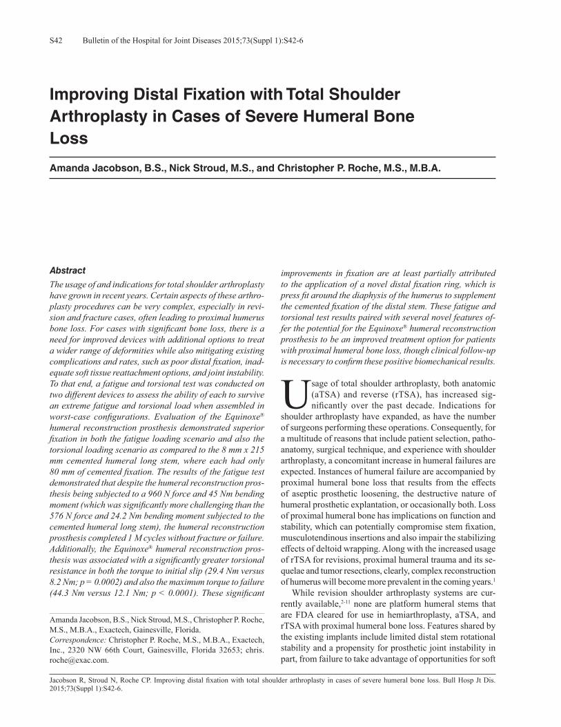
Bulletin of the Hospital for Joint Diseases 2015;73(Suppl 1):S42-6S42
Jacobson R, Stroud N, Roche CP. Improving distal fixation with total shoulder arthroplasty in cases of severe humeral bone loss. Bull Hosp Jt Dis. 2015;73(Suppl 1):S42-6.
Abstract
The usage of and indications for total shoulder arthroplasty have grown in recent years. Certain aspects of these arthro-plasty procedures can be very complex, especially in revi-sion and fracture cases, often leading to proximal humerus bone loss. For cases with significant bone loss, there is a need for improved devices with additional options to treat a wider range of deformities while also mitigating existing complications and rates, such as poor distal fixation, inad-equate soft tissue reattachment options, and joint instability. To that end, a fatigue and torsional test was conducted on two different devices to assess the ability of each to survive an extreme fatigue and torsional load when assembled in worst-case configurations. Evaluation of the Equinoxe® humeral reconstruction prosthesis demonstrated superior fixation in both the fatigue loading scenario and also the torsional loading scenario as compared to the 8 mm x 215 mm cemented humeral long stem, where each had only 80 mm of cemented fixation. The results of the fatigue test demonstrated that despite the humeral reconstruction pros-thesis being subjected to a 960 N force and 45 Nm bending moment (which was significantly more challenging than the 576 N force and 24.2 Nm bending moment subjected to the cemented humeral long stem), the humeral reconstruction prosthesis completed 1 M cycles without fracture or failure. Additionally, the Equinoxe® humeral reconstruction pros-thesis was associated with a significantly greater torsional resistance in both the torque to initial slip (29.4 Nm versus 8.2 Nm; p = 0.0002) and also the maximum torque to failure (44.3 Nm versus 12.1 Nm; p < 0.0001). These significant
improvements in fixation are at least partially attributed to the application of a novel distal fixation ring, which is press fit around the diaphysis of the humerus to supplement the cemented fixation of the distal stem. These fatigue and torsional test results paired with several novel features of-fer the potential for the Equinoxe® humeral reconstruction prosthesis to be an improved treatment option for patients with proximal humeral bone loss, though clinical follow-up is necessary to confirm these positive biomechanical results.
Usage of total shoulder arthroplasty, both anatomic (aTSA) and reverse (rTSA), has increased sig-nificantly over the past decade. Indications for
shoulder arthroplasty have expanded, as have the number of surgeons performing these operations. Consequently, for a multitude of reasons that include patient selection, patho-anatomy, surgical technique, and experience with shoulder arthroplasty, a concomitant increase in humeral failures are expected. Instances of humeral failure are accompanied by proximal humeral bone loss that results from the effects of aseptic prosthetic loosening, the destructive nature of humeral prosthetic explantation, or occasionally both. Loss of proximal humeral bone has implications on function and stability, which can potentially compromise stem fixation, musculotendinous insertions and also impair the stabilizing effects of deltoid wrapping. Along with the increased usage of rTSA for revisions, proximal humeral trauma and its se-quelae and tumor resections, clearly, complex reconstruction of humerus will become more prevalent in the coming years.1 While revision shoulder arthroplasty systems are cur-rently available,2-11 none are platform humeral stems that are FDA cleared for use in hemiarthroplasty, aTSA, and rTSA with proximal humeral bone loss. Features shared by the existing implants include limited distal stem rotational stability and a propensity for prosthetic joint instability in part, from failure to take advantage of opportunities for soft
Improving Distal Fixation with Total Shoulder Arthroplasty in Cases of Severe Humeral Bone Loss
Amanda Jacobson, B.S., Nick Stroud, M.S., and Christopher P. Roche, M.S., M.B.A.
Amanda Jacobson, B.S., Nick Stroud, M.S., Christopher P. Roche, M.S., M.B.A., Exactech, Gainesville, Florida. Correspondence: Christopher P. Roche, M.S., M.B.A., Exactech, Inc., 2320 NW 66th Court, Gainesville, Florida 32653; [email protected].

S43Bulletin of the Hospital for Joint Diseases 2015;73(Suppl 1):S42-6
tissue tension and its attachment to the bone or prosthesis.6-11 Aiming to improve both stability and fixation in such difficult revision cases, Exactech has developed the Equinoxe® hu-meral reconstruction prosthesis (Fig. 1). This unique device has gained FDA clearance for shoulder reconstructions that incorporate hemiarthroplasty, aTSA, and rTSA in the pres-ence of significant proximal humeral bone loss.12 This highly modular device is composed of solution heated-treated and aged Ti-6Al-4V and consists of a cemented distal stem (6 mm to 13 mm), a press-fit distal fixation collars (17 mm to 33 mm), middle segments (25 mm to 75 mm), and an electro-polished proximal body (four sizes, in two different heights). In combination, this size offering permits humeral reconstructions from 50 mm to 222.5 mm from the top of the
humeral head in 12.5 mm increments. These segments are secured together by taper impaction and are locked using a screw which spans the entire distance from the distal stem to the proximal body. Additionally, the Equinoxe® humeral re-construction prosthesis provides four different sizes of proxi-mal bodies to lateralize the deltoid and encourages additional deltoid wrapping to improve stability. These proximal bodies include numerous recessed plasma-coated regions for soft tissue attachment that are surrounded by suture grooves to avoid suture abrasion (Figs. 2 and 3). The purpose of this study was to analyze and compare the distal fixation that results when the novel Equinoxe® humeral reconstruction prosthesis and the existing Equinoxe® cemented humeral long stem are tested in a simulated humeral reconstruction using two different extreme loading scenarios (fatigue and torsion).
MethodologyThis biomechanical study consists of two different tests. The first test quantifies the fatigue resistance of the Equi-noxe® humeral reconstruction prosthesis and the Equinoxe® cemented humeral long stem when oriented and assembled in worst case configurations and utilized in a mid-humeral resection with a minimum 80 mm cemented stem length. The second test quantifies the resistance of each aforementioned cemented humeral stem to a static torsional load. For the fatigue test, the humeral reconstruction prosthesis was tested with a 6 mm x 80 mm distal stem using two 75 mm middle segments, which is the longest recommended configuration with the smallest humeral stem and therefore represents a worst-case configuration because it creates the largest moment under loading. The Equinoxe cemented humeral long stem tested was 8 mm x 215 mm, which was larger than the 6 mm diameter of the humeral reconstruction prosthesis. The loading parameters between the two stems were different with the cemented humeral long stem being tested under a significantly less extreme loading orientation because previous feasibility testing demonstrated immediate failure when tested identically. These differences are outlined in Table 1. The cemented humeral long stem was tested at 1.5 Hz with a peak force of 576 N until 1 M cycles or fail-ure. Conversely, the humeral reconstruction prosthesis was
Figure 1 Equinoxe® humeral reconstruction prosthesis (Exactech, Inc.; Gainesville, FL).
Figure 2 Four sizes of proximal body options to lateralize the proximal humerus to improve soft tissue tensioning and increase deltoid wrapping.
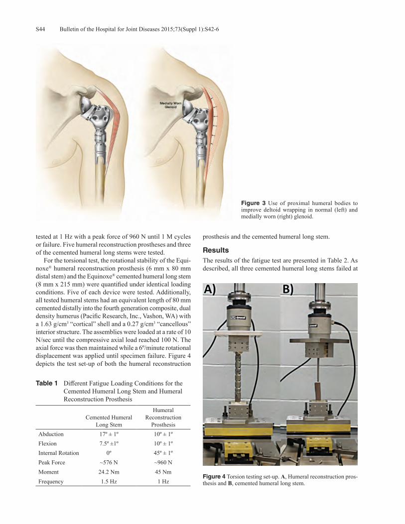
Bulletin of the Hospital for Joint Diseases 2015;73(Suppl 1):S42-6S44
tested at 1 Hz with a peak force of 960 N until 1 M cycles or failure. Five humeral reconstruction prostheses and three of the cemented humeral long stems were tested. For the torsional test, the rotational stability of the Equi-noxe® humeral reconstruction prosthesis (6 mm x 80 mm distal stem) and the Equinoxe® cemented humeral long stem (8 mm x 215 mm) were quantified under identical loading conditions. Five of each device were tested. Additionally, all tested humeral stems had an equivalent length of 80 mm cemented distally into the fourth generation composite, dual density humerus (Pacific Research, Inc., Vashon, WA) with a 1.63 g/cm3 “cortical” shell and a 0.27 g/cm3 “cancellous” interior structure. The assemblies were loaded at a rate of 10 N/sec until the compressive axial load reached 100 N. The axial force was then maintained while a 6º/minute rotational displacement was applied until specimen failure. Figure 4 depicts the test set-up of both the humeral reconstruction
prosthesis and the cemented humeral long stem.
ResultsThe results of the fatigue test are presented in Table 2. As described, all three cemented humeral long stems failed at
Table 1 Different Fatigue Loading Conditions for the Cemented Humeral Long Stem and Humeral Reconstruction Prosthesis
Cemented Humeral Long Stem
Humeral Reconstruction
ProsthesisAbduction 17º ± 1º 10º ± 1ºFlexion 7.5º ±1º 10º ± 1ºInternal Rotation 0º 45º ± 1ºPeak Force ~576 N ~960 NMoment 24.2 Nm 45 NmFrequency 1.5 Hz 1 Hz
Figure 3 Use of proximal humeral bodies to improve deltoid wrapping in normal (left) and medially worn (right) glenoid.
Figure 4 Torsion testing set-up. A, Humeral reconstruction pros-thesis and B, cemented humeral long stem.

S45Bulletin of the Hospital for Joint Diseases 2015;73(Suppl 1):S42-6
an average of 218,914 ± 167,338 cycles, whereas all five humeral reconstruction prostheses completed 1 M cycles without failure at nearly twice the applied torque. All three cemented humeral long stems were tested in composite hu-meri; whereas, two of the humeral reconstruction prostheses were tested in composite humeri and three were tested in hollow aluminum pipe. This difference in substrate was due to the more extreme forces and torques applied to the humeral reconstruction prosthesis compared to the cemented humeral long stem. It was assumed that the composite humerus specimens would indicate the quality of fixation between implant and irregularly shaped humerus, as well as stress the 6 mm diameter humeral stem. In contrast, the rigid fixation provided by the aluminum cylinders was assumed to provide higher stresses at the distal fixation ring given the increased stiffness at the implant-aluminum boundary. Regardless of the substrate, all five of the reconstruction prostheses survived loading without fracture or failure. The results of the torsional test are presented in Table 3. As described, the average applied torque to initiate slipping of the cemented humeral long stem was 8.2 Nm versus 29.4 Nm for the humeral reconstruction prosthesis. Additionally,
the average max torque to failure of the cemented humeral long stem was 12.1 Nm versus 44.3 Nm for the humeral reconstruction prosthesis. For all samples, the humeral reconstruction prosthesis withstood higher torques than the cemented humeral long stem, with an average torque differ-ence of 21.1 Nm and 32.1 Nm for slipping and max torque, respectively.
DiscussionThese results demonstrate both superior fatigue and torsional strength of the Equinoxe® humeral reconstruction prosthesis relative to the 8 mm x 215 mm cemented humeral long stem, where each had only 80 mm of cemented stem fixation. De-spite the Equinoxe® humeral reconstruction prosthesis being subjected to a 960 N force and 45 Nm bending moment in the fatigue test (which was significantly more challenging than the 576 N force and 24.2 Nm bending moment subjected to the Equinoxe cemented humeral long stem), the humeral reconstruction stem reached 1 M cycles without fracture or failure despite this 56.3% higher peak forces. Additionally, the Equinoxe® humeral reconstruction prosthesis was as-sociated with a significantly greater torsional resistance in
Table 2 Fatigue Life for the Humeral Reconstruction Prosthesis and the Cemented Humeral Long Stem
Sample # Cycles to FailureCemented Length/Moment
Arm Length (mm) Humerus Material
Cemented Humeral Long Stem1 200,711 98 / 117 Composite Humeri2 61,392 83 / 132 Composite Humeri3 394,640 92 / 123 Composite HumeriAverage 218,914 ± 167,338 91 / 124
Humeral Reconstruction Prosthesis1 1,000,000 (run-out) 80 / 191 Composite Humeri2 1,000,000 (run-out) 80 / 191 Composite Humeri3 1,000,000 (run-out) 80 / 191 Aluminum Pipe4 1,000,000 (run-out) 80 / 191 Aluminum Pipe5 1,000,000 (run-out) 80 / 191 Aluminum PipeAverage 1,000,000 ± 0 80 / 191
Table 3 The torque to Initiate Slipping and the Peak Torque for the Humeral Reconstruction Prosthesis and the Cemented Humeral Long Stem
Humeral Reconstruction Prosthesis Cemented Humeral Long Stem
SampleTorque to Initiate
Slipping (Nm)Maximum Torque
(Nm)Torque to Initiate
Slipping (Nm)Maximum Torque
(Nm)1 22.6 48.5 14.0 14.02 34.3 49.4 5.1 7.03 24.2 39.0 11.0 12.54 35.7 45.4 5.1 10.45 29.4 39.2 5.8 16.6Average 29.4± 5.9 44.3 ± 5.0 8.2 ±4.1 12.1 ±3.7P-value (comparison of stems) 0.0002 < 0.0001 0.0002 < 0.0001

Bulletin of the Hospital for Joint Diseases 2015;73(Suppl 1):S42-6S46
toque to initial slip (29.4 Nm versus 8.2 Nm; p = 0.0002) and also in maximum torque to failure (44.3 Nm versus 12.1 Nm; p < 0.0001) This study is limited by the use of a relatively small sample size in each test, the different loading conditions in the fatigue test, and also by the use of a composite humeri substrate instead of cadaveric bone. When comparing these torque-to-failure values in this study to that of cadaveric humeri in a study by Schopfer13 (humeri of an average age of 75 years), the reported peak torque to failure was 53 Nm ± 17 Nm. While this torque to failure of cadaveric bone was greater than either value in this study, it is worth noting that the Equinoxe® humeral reconstruction prosthesis was much closer to the reported torsional strength of the cadaveric humeral bone—and it may not be reasonable to expect a reconstructed humeral arthroplasty to approach the torsional strength of the native bone. The significant increases in tor-sional strength relative to the cemented humeral long stem is likely attributed to the distal fixation ring component. Future testing should isolate the additive impact of the distal collars on rotational stability, particularly when utilized in different bone morphologies or different density of bone. However, it is clear based on these results that the diaphyseal fit of this component provides a significant advantage compared to cemented stems without a similar supplemental means for distal fixation. Finally, as all tested Equinoxe® humeral reconstruction prostheses completed 1 M cycles in the fa-tigue test, the test was stopped for each component prior to failure. Therefore, future work should continue to test this device using the same methodology until failure in order to better identify the fatigue limits and failure modalities.
Conclusions These fatigue and torsional study results demonstrate that the Equinoxe® humeral reconstruction prosthesis offers the potential for improved strength and stability when used with severe proximal bone loss, relative to the cemented humeral long stem. Patients with severe humeral bone loss may benefit from such a device with improved distal fixa-tion and additional options for joint stability and soft tissue attachment. Clinical follow-up is necessary to confirm these positive biomechanical results.
Conflict of Interest StatementFunding for this study was provided by Exactech, Inc. Amanda Jacobson, B.S., Nick Stroud, M.S., and Christopher P. Roche, M.S., M.B.A., are employees of Exactech, Inc., Gainesville, Florida.
References1. Day JS, Ramsey ML, Lau E, Williams GR. Risk of venous
thromboembolism after shoulder arthroplasty in the Medicare population. J Shoulder Elbow Surg. 2015 Jan;24(1):98-105.
2. 510(k) Premarket Notification Database Search3. Biomet. Mosaic How To Do Guide. Biomet Orthopedic,
Bridgend, South Wales (2002)4. Biomet. Mosaic Humeral Replacement System. Warsaw,
Indiana: Biomet Orthopedics, 2002.5. Biomet. Comprehensive Segmental Revision System Surgical
Technique. Warsaw, Indiana: Biomet Orthopedics, 2012.6. Kumar D, Grimer RJ, Abudu A, et al. Endoprosthetic replace-
ment of the proximal humerus: Long term results. J Bone Joint Surg Br. 2003 Jul;85(5):717-22.
7. Van De Sande MA, Dijkstra PD, Taminiau AH. Proximal humerus reconstruction after tumour resection: Biologi-cal versus endoprosthetic reconstruction. Int Orthop. 2011 Sep;35(9):1375-380.
8. Zeegen MD, Aponte-Tinao LA, Hornicek FJ, et al. Survivor-ship analysis of 141 modular metallic endoprostheses at early followup. Clin Orthop Relat Res. 2003 Mar;(420):239-50.
12. 510(k) Summary K143659: Exactech Inc. Equinoxe Humeral Reconstruction Prosthesis.
9. Marulanda GA, Henderson E, Cheong D, Letson GD. Proxi-mal and total humerus reconstruction with the use of an aor-tograft mesh. Clin Orthop Relat Res. 2010 Nov;468(11):2896-903.
10. Black AW Szabo RM, Titelman RM. Treatment of malignant tumors of the proximal humerus with allograft-prosthesis composite reconstruction. J Shoulder Elbow Surg. 2007 Sep-Oct;16(5):525-33.
11. Squire G, Grundy TJ, Ferran NA, et al. Long-term survival of proximal humerus allografts for reconstruction following resection of malignant bone tumors. Acta Orthop Belg. 2013 Jun;79(3):260-5.
13. Schopfer A, Hearn TC, Malisano L, et al. Comparison of tor-sional strength of humeral intramedullary nailing: A cadaveric study. J Orthop Trauma. 1994 Oct;8(5):414-21.

S47Bulletin of the Hospital for Joint Diseases 2015;73(Suppl 1):S47-51
Hamilton MA, Polakovic S, Saadi P, Jones RB, Parsons IM, Cheung, EV. Evaluation of preoperative implant placement in total shoulder arthroplasty. Bull Hosp Jt Dis. 2015;73(Suppl 1):S47-51.
Abstract
Introduction: New technology to assist with glenoid placement in shoulder arthroplasty has evolved to include preoperative planning tools and intraoperative guides. These tools provide surgeons with a more complete understanding of glenoid anatomy prior to surgery. However, there have been no studies identifying the information that most influences surgical decision making. Further, there have been few studies that quantify intraoperative identification of scapular land-marks required to execute a preoperative plan. The purpose of this study is to examine the variables that are considered when making a preoperative plan in shoulder arthroplasty. Methods: The first part of this study was a cadaveric lab in which three surgeons identified the neutral axis in surgical simulation. The second part of the study utilized a preliminary software tool in which surgeons were able to place glenoid implants in a set of CT reconstructions utilizing standard pegged glenoid components. In the third part of the study, surgeons utilized a novel planning software that included the ability to view the 3D reconstructed glenoid in all planes si-multaneously and place either standard or augmented glenoid implants. The results of these three studies were compared. Results: The center of the glenoid identified in the cadaver lab was 1.69 mm ± 1.58 mm anterior and 1.99 mm ± 2.49 mm superior to center. The identified neutral axis was tilted
14.2° ± 9.2° superior to the Friedman axis with 11.8° ± 7.9° of retroversion relative to that axis. Using the novel preoperative planning tool, the surgeons placed implants less than 0.5 mm from the center of the glenoid (AP = -0.07 mm ± 0.42 mm, SI = 0.44 mm ± 0.82 mm) with an average retroversion of less than 1° (-0.96° ± 3.04°). Conclusion: There was a discernible difference between the neutral axis identified in the cadaveric simulation (aver-age of 14.2° superior and 11.8° retroverted) and the implant orientation planned using preoperative software (average of 3.26° superior and 0.96° retroverted). Based on the variability of position and orientation seen cadaverically, it is concluded that additional intraoperative guidance is needed alongside a preoperative plan in order to execute ideal placement of the glenoid component.
As advanced imaging modalities in the shoulder continue to expand, the surgeon has more powerful tools to optimize surgical precision and techniques.
In total shoulder arthroplasty, computerized tomography (CT) scans provide valuable insight into patient bony anat-omy of the glenoid that cannot be fully appreciated during actual surgery.1 Simply visualizing the 3D form of the bone has been credited for improving a surgeon’s preparation pre-operatively. Recently, tools have emerged that expand on a simple 3D representation and provide complete preoperative planning of the scapula, including implant options. Planning a case preoperatively allows the surgeon to anticipate clini-cal challenges (e.g., perforation, version correction, bony anomalies). Multiple studies have compared a surgeon’s plan to the placement achieved using instrumentation or patient specific guides.2,3 The data show that with traditional instrumentation, a surgeon can generally place an implant within 15° of neutral in terms of retroversion and inclination, but with higher degrees of preoperative deformity, the opera-tive placement is less predictable. Iannotti and coworkers
Evaluation of Preoperative Implant Placement in Total Shoulder Arthroplasty
Matthew A. Hamilton, Ph.D., Sandrine Polakovic, M.S., Paul Saadi, M.D., Richard B. Jones, M.D., Ira M. Parsons, M.D., and Emilie V. Cheung, M.D.
Matthew A. Hamilton, Ph.D., and Sandrine Polakovic, M.S., Ex-actech, Inc., Gainesville, Florida. Paul Saadi, M.D., Dallas Bone and Joint Clinic, Dallas, Texas. Richard B. Jones, M.D., Southeast-ern Sports Medicine, Asheville, North Carolina. Ira M. Parsons, M.D., Seacoast Orthopaedics, Somersworth, New Hampshire. Emilie V. Cheung, M.D., Department of Orthopaedic, Stanford University, Stanford, California.Correspondence: Matthew A. Hamilton, Ph.D., Exactech, Inc., 2320 NW 66th Court, Gainesville, Florida 32653; [email protected].

Bulletin of the Hospital for Joint Diseases 2015;73(Suppl 1):S47-51S48
described a method for identifying the “glenoid vault” of the scapula in order to provide guidance on the proper implant alignment.4,5 By fitting the idealized glenoid vault shape to the deformed scapular bone, the software utilized in their study made a recommendation on the proper position and orientation of the glenoid component using the assumption that the center of the glenoid vault was the ideal placement for the center of the glenoid implant. However, the subtleties behind preoperative and intraop-erative surgical decision making have yet to be quantified. The goal of this study is to document the variables consid-ered when implanting a glenoid prosthesis. The center of the glenoid prosthesis was quantified relative to Friedman’s line during three scenarios: 1. utilizing simulated surgery in a cadaver lab, 2. utilizing “virtual surgery” in which glenoid components were placed within 3D CT scapulae with standard non-augmented components, and 3. utilizing “virtual surgery” in which glenoid components were placed within 3D imaging of the scapula using augmented glenoid components.
Materials and MethodsSimulated Surgery Using CadaversNine cadaveric shoulders were used in the simulated surgery portion of the study. Three surgeons (EC, PS, RJ) exposed the shoulder joint utilizing a deltopectoral approach in each specimen. The humerus was prepared by making a cut along the anatomic neck of the humerus as determined by the sur-geon. The ExactechGPS® navigation system (Gainesville, FL) was used to capture points on the scapular bone for use in registration with the 3D reconstruction of the bone. After capture of the scapular points, the system was used to track the position of the scapula relative to the probe for each cadaver. The surgeons were asked to identify the center of the glenoid using a tracked probe tip (Fig. 1). They were then asked to orient a shaft along the neutral axis of the scapula for reaming. The navigation system simply collected data throughout this process. It provided no guidance on align-ment during assessment of the glenoid. The surgeons were only allowed to select the data one time per specimen and then had to move to the next. This rotation was repeated until each surgeon collected data on the specimen three times to minimize the influence of repeated data collection.
Glenoid Placement Using Preliminary SoftwareThe nine cadaveric specimens used in the first portion of this study were CT scanned prior to the simulated surgeries. CT scans were reconstructed using Mimics® Innovation Suite v16.0 (Leuven, Belgium). Each image or slice of the scan was manually segmented using a threshold technique to discern the cortical bone geometry of the slice. The slices were merged to create the 3D representation of each scapula. The 3D reconstructions were imported into a 3D modeling software (Unigraphics NX 7.5, Siemens Inc., Plano, TX) along with a pegged glenoid component. Two orthopedic surgeons (EC and PS) used the software to place standard glenoid implants onto the scapulae based on their preferred
positioning. No scapular coordinate system was defined in this software and parts were placed solely on the subjective determination of the “best fit.” After glenoid placement, a coordinate system was built for the scapula within Geomagic DesignTM X based on the Friedman axis. The coordinate system was constructed by identifying the center of the tri-gonum on the medial border of the scapula, the distal-most point, and the geometric center of the glenoid. The version and inclination of the reconstructed scapulae were measured. The position and orientation of each gle-noid component were compared to the “neutral” axis of the scapula as defined by the Friedman axis, and the “neutral” axis that was identified intraoperatively.6
Glenoid Placement Using Novel Preoperative Planning SoftwareAn additional 10 previously obtained unrelated CT scans were reconstructed using custom-written CT segmentation software (Blue Ortho, Grenoble, France) following a similar threshold-based process. These reconstructions along with the CT images were imported into custom-written preopera-tive planning software (Blue Ortho, Grenoble, France) in which the surgeons could perform “virtual surgery.” Both traditional glenoid implants and augmented implants were available for selection. The software also included the abil-ity to visualize the CT slices and the identified axes of the scapula. The position and orientation of the implant followed the Friedman axis. Each surgeon positioned their selected implant in the preferred position and orientation. These positions were measured relative to the previously defined coordinate system of the scapula. Differences between “ideal” placement of the glenoid and the neutral position were then calculated. The results of glenoid placement using the preliminary software and the novel software were compared using a Student’s t-test. An unpaired, two-tailed t-test was chosen since the two datasets are independent of one another.
ResultsSimulated Surgery Using CadaversThe nine cadaveric specimens were assessed in a simulated surgery. The point identified as the center of the glenoid in the cadaver lab was anterior and superior to the geometric center identified using the 3D reconstruction of the bone. The average offset was 1.69 mm ± 1.58 mm anterior and 1.99 mm ± 2.49 mm superior to the center (Fig. 2). The identified neutral axis was generally tilted superior to the Friedman axis and in a greater degree of retroversion. The average retroversion was 11.8° ± 7.9°, and the average inclination was 14.2° ± 9.2° of superior tilt. The “neutral” axis identified cadaverically correlated with the retroversion of the bone.
Glenoid Placement Using Preliminary SoftwareThe glenoid placement using the preliminary software tool was closer to the center than what was identified in the cadaver lab. The average position for the virtually placed

S49Bulletin of the Hospital for Joint Diseases 2015;73(Suppl 1):S47-51
glenoids was 0.41 mm ± 1.09 mm anterior to the glenoid center and 0.69 mm ± 1.65 mm superior to the glenoid center. The difference between the glenoid component and the neutral axis (8.88° ± 4.69° retroverted and 4.35° ± 6.04° inferior tilt) was less than the difference between the neutral axis identified cadaverically and the actual neutral axis. The key factors used to determine the placement of the implant
were bony coverage, fixation pegs within the body of the scapula, version correction, and subchondral bone preser-vation. These considerations were cited as reasons why the implants were not placed in the neutral position.
Glenoid Placement Using Novel Preoperative Planning SoftwareThe glenoid placement using the novel custom-written planning tool on an additional 10 CT scans demonstrated an implant placement closer to the center of the glenoid face than simply using the 3D reconstructions of the bone with no coordinate system defined (0.07 mm ± 0.42 mm posterior to the center and 0.44 mm ± 0.82 mm superior to the center). The orientation of the glenoid using the novel software tool was corrected closer to the neutral axis than what was found in the initial placement study using the preliminary software tool (3.26° ± 4.25° superiorly tilted and 0.96° ± 3.04° of retroversion). A Student’s t-test (two-tailed, un-paired) was performed on the two datasets (Table 1) and revealed that the implant retroversion was the only variable to reach statistical significance. However, the preliminary software tool only allowed standard pegged glenoid options and did not include the ability to select augmented implants. Subchondral bone preservation was noted as a consideration when placing the implants, and many implants were placed in retroversion in order to balance version correction and bone preservation. The addition of augmented glenoid
Figure 1 The probe used in this study consists of a handle with active trackers for positioning and a spherical tip used to probe the surface. The axis of this probe was used to identify the neutral axis in the cadaveric assessment.
Figure 2 Cadaveric assessment of glenoid center position (left). Neu-tral axis inclination identified on cadaver (right-top, red), measured inclination using 3D representa-tion (right-top, blue). Neutral axis retroversion identified on cadavers (right-bottom, red), measured in-clination using 3D representation (right-bottom, blue).
Figure 3 Use of augmented gle-noids as a function of measured retroversion. Beyond 10° of ret-roversion most surgeons select an augmented implant to help preserve chondral bone.
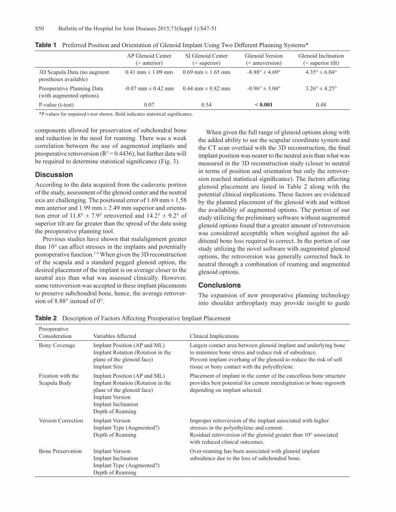
Bulletin of the Hospital for Joint Diseases 2015;73(Suppl 1):S47-51S50
components allowed for preservation of subchondral bone and reduction in the need for reaming. There was a weak correlation between the use of augmented implants and preoperative retroversion (R2 = 0.4436), but further data will be required to determine statistical significance (Fig. 3).
DiscussionAccording to the data acquired from the cadaveric portion of the study, assessment of the glenoid center and the neutral axis are challenging. The positional error of 1.69 mm ± 1.58 mm anterior and 1.99 mm ± 2.49 mm superior and orienta-tion error of 11.8° ± 7.9° retroverted and 14.2° ± 9.2° of superior tilt are far greater than the spread of the data using the preoperative planning tool. Previous studies have shown that malalignment greater than 10° can affect stresses in the implants and potentially postoperative function.7-9 When given the 3D reconstruction of the scapula and a standard pegged glenoid option, the desired placement of the implant is on average closer to the neutral axis than what was assessed clinically. However, some retroversion was accepted in these implant placements to preserve subchondral bone, hence, the average retrover-sion of 8.88° instead of 0°.
When given the full range of glenoid options along with the added ability to see the scapular coordinate system and the CT scan overlaid with the 3D reconstruction, the final implant position was nearer to the neutral axis than what was measured in the 3D reconstruction study (closer to neutral in terms of position and orientation but only the retrover-sion reached statistical significance). The factors affecting glenoid placement are listed in Table 2 along with the potential clinical implications. These factors are evidenced by the planned placement of the glenoid with and without the availability of augmented options. The portion of our study utilizing the preliminary software without augmented glenoid options found that a greater amount of retroversion was considered acceptable when weighed against the ad-ditional bone loss required to correct. In the portion of our study utilizing the novel software with augmented glenoid options, the retroversion was generally corrected back to neutral through a combination of reaming and augmented glenoid options.
ConclusionsThe expansion of new preoperative planning technology into shoulder arthroplasty may provide insight to guide
Table 2 Description of Factors Affecting Preoperative Implant PlacementPreoperative Consideration Variables Affected Clinical ImplicationsBony Coverage Implant Position (AP and ML)
Implant Rotation (Rotation in the plane of the glenoid face)Implant Size
Largest contact area between glenoid implant and underlying bone to minimize bone stress and reduce risk of subsidence.Prevent implant overhang of the glenoid to reduce the risk of soft tissue or bony contact with the polyethylene.
Fixation with the Scapula Body
Implant Position (AP and ML)Implant Rotation (Rotation in the plane of the glenoid face)Implant VersionImplant InclinationDepth of Reaming
Placement of implant in the center of the cancellous bone structure provides best potential for cement interdigitation or bone ingrowth depending on implant selected.
Version Correction Implant VersionImplant Type (Augmented?)Depth of Reaming
Improper retroversion of the implant associated with higher stresses in the polyethylene and cement.Residual retroversion of the glenoid greater than 10° associated with reduced clinical outcomes.
Bone Preservation Implant VersionImplant InclinationImplant Type (Augmented?)Depth of Reaming
Over-reaming has been associated with glenoid implant subsidence due to the loss of subchondral bone.
Table 1 Preferred Position and Orientation of Glenoid Implant Using Two Different Planning Systems*AP Glenoid Center
(+ anterior)SI Glenoid Center
(+ superior)Glenoid Version(+ anteversion)
Glenoid Inclination(+ superior tilt)
3D Scapula Data (no augment prostheses available)
0.41 mm ± 1.09 mm 0.69 mm ± 1.65 mm -8.88° ± 4.69° 4.35° ± 6.04°
Preoperative Planning Data(with augmented options)
-0.07 mm ± 0.42 mm 0.44 mm ± 0.82 mm -0.96° ± 3.04° 3.26° ± 4.25°
P-value (t-test) 0.07 0.54 < 0.001 0.48*P-values for unpaired t-test shown. Bold indicates statistical significance.
S51Bulletin of the Hospital for Joint Diseases 2015;73(Suppl 1):S47-51
intraoperative decision making. However, based on the data in this study, intraoperative guidance must be provided to execute these plans effectively. The error associated with a free-hand technique for identifying the neutral axis of the scapula in cadavers was greater than 10° in both version and inclination, making it difficult to accurately place an implant as planned without intraoperative guidance. The shoulder joint is primarily soft-tissue balanced, and while these planning tools can help guide position and orientation, they have little ability to predict the response of these tissues. Hence, the subtleties of proper joint tension remain in the hands of the surgeon.
Conflict of Interest StatementFunding for this study was provided by Exactech, Inc. Mat-thew A. Hamilton, Ph.D., and Sandrine Polakovic, M.S., are employees of Exactech, Inc. Paul Saadi, M.D., Richard B. Jones, M.D., Ira M. Parsons, M.D., and Emilie V. Cheung, M.D., are consultants for Exactech, Inc., Gainesville, Florida.
References1. Scalise JJ, Codsi MJ, Bryan J, et al. The influence of three-
dimensional computed tomography images of the shoulder in preoperative planning for total shoulder arthroplasty. J Bone Joint Surg Am. 2008 Nov;90(11):2438-45.
2. Hendel MD, Bryan JA, Barsoum WK, et al. Comparison of Patient-Specific Instruments with Standard Surgical Instru-
ments in Determining Glenoid Component Position A Ran-domized Prospective Clinical Trial. J Bone Joint Surg Am. 2012 Dec 5;94(23):2167-75.
3. Throckmorton TW, Gulotta LV, Bonnarens FO, et al. Patient-specific targeting guides compared with traditional instru-mentation for glenoid component placement in shoulder arthroplasty: a multi-surgeon study in 70 arthritic cadaver specimens. J Shoulder Elbow Surg. 2015 Jun;24(6):965-71.
4. Codsi MJ, Bennetts C, Gordiev K, et al. Normal glenoid vault anatomy and validation of a novel glenoid implant shape. J Shoulder Elbow Surg. 2008 May-Jun;17(3):471-8.
5. Ganapathi A, McCarron JA, Chen X, Iannotti JP. Predict-ing normal glenoid version from the pathologic scapula: a comparison of 4 methods in 2- and 3-dimensional models, J Shoulder Elbow Surg. 2011 Mar;20(2):234-44.
6. Friedman RJ, Hawthorne KB, Genez BM. The use of com-puterized tomography in the measurement of glenoid version. J Bone Joint Surg Am. 1992 Aug;74(7):1032-7.
7. Hopkins AR, Hansen UN, Amis AA, Emery R. The effects of glenoid component alignment variations on cement mantle stresses in total shoulder arthroplasty, J Shoulder Elbow Surg. 2004 Nov-Dec;13(6):668-75.
8. Terrier A, Büchler P, Farron A. Bone-cement interface of the glenoid component: Stress analysis for varying cement thick-ness. Clin Biomech (Bristol, Avon). 2005 Aug;20(7)710-7.
9. Gregory TM, Sankey A, Augereau B, et al. Accuracy of gle-noid component placement in total shoulder arthroplasty and its effect on clinical and radiological outcome in a retrospec-tive, longitudinal, monocentric open study. PLoS ONE. 2013 Oct;8(10):e75791.
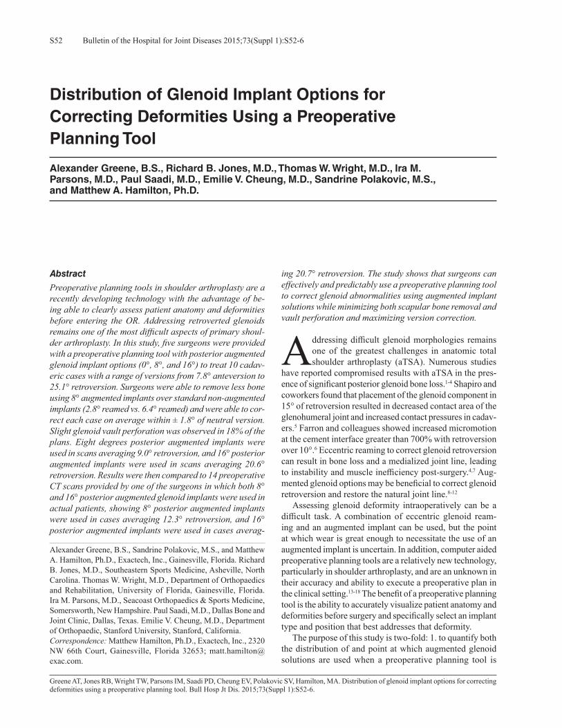
Bulletin of the Hospital for Joint Diseases 2015;73(Suppl 1):S52-6S52
Greene AT, Jones RB, Wright TW, Parsons IM, Saadi PD, Cheung EV, Polakovic SV, Hamilton, MA. Distribution of glenoid implant options for correcting deformities using a preoperative planning tool. Bull Hosp Jt Dis. 2015;73(Suppl 1):S52-6.
Abstract
Preoperative planning tools in shoulder arthroplasty are a recently developing technology with the advantage of be-ing able to clearly assess patient anatomy and deformities before entering the OR. Addressing retroverted glenoids remains one of the most difficult aspects of primary shoul-der arthroplasty. In this study, five surgeons were provided with a preoperative planning tool with posterior augmented glenoid implant options (0°, 8°, and 16°) to treat 10 cadav-eric cases with a range of versions from 7.8° anteversion to 25.1° retroversion. Surgeons were able to remove less bone using 8° augmented implants over standard non-augmented implants (2.8° reamed vs. 6.4° reamed) and were able to cor-rect each case on average within ± 1.8° of neutral version. Slight glenoid vault perforation was observed in 18% of the plans. Eight degrees posterior augmented implants were used in scans averaging 9.0° retroversion, and 16° posterior augmented implants were used in scans averaging 20.6° retroversion. Results were then compared to 14 preoperative CT scans provided by one of the surgeons in which both 8° and 16° posterior augmented glenoid implants were used in actual patients, showing 8° posterior augmented implants were used in cases averaging 12.3° retroversion, and 16° posterior augmented implants were used in cases averag-
ing 20.7° retroversion. The study shows that surgeons can effectively and predictably use a preoperative planning tool to correct glenoid abnormalities using augmented implant solutions while minimizing both scapular bone removal and vault perforation and maximizing version correction.
Addressing difficult glenoid morphologies remains one of the greatest challenges in anatomic total shoulder arthroplasty (aTSA). Numerous studies
have reported compromised results with aTSA in the pres-ence of significant posterior glenoid bone loss.1-4 Shapiro and coworkers found that placement of the glenoid component in 15° of retroversion resulted in decreased contact area of the glenohumeral joint and increased contact pressures in cadav-ers.5 Farron and colleagues showed increased micromotion at the cement interface greater than 700% with retroversion over 10°.6 Eccentric reaming to correct glenoid retroversion can result in bone loss and a medialized joint line, leading to instability and muscle inefficiency post-surgery.4,7 Aug-mented glenoid options may be beneficial to correct glenoid retroversion and restore the natural joint line.8-12
Assessing glenoid deformity intraoperatively can be a difficult task. A combination of eccentric glenoid ream-ing and an augmented implant can be used, but the point at which wear is great enough to necessitate the use of an augmented implant is uncertain. In addition, computer aided preoperative planning tools are a relatively new technology, particularly in shoulder arthroplasty, and are an unknown in their accuracy and ability to execute a preoperative plan in the clinical setting.13-18 The benefit of a preoperative planning tool is the ability to accurately visualize patient anatomy and deformities before surgery and specifically select an implant type and position that best addresses that deformity. The purpose of this study is two-fold: 1. to quantify both the distribution of and point at which augmented glenoid solutions are used when a preoperative planning tool is
Distribution of Glenoid Implant Options for Correcting Deformities Using a Preoperative Planning Tool
Alexander Greene, B.S., Richard B. Jones, M.D., Thomas W. Wright, M.D., Ira M. Parsons, M.D., Paul Saadi, M.D., Emilie V. Cheung, M.D., Sandrine Polakovic, M.S., and Matthew A. Hamilton, Ph.D.
Alexander Greene, B.S., Sandrine Polakovic, M.S., and Matthew A. Hamilton, Ph.D., Exactech, Inc., Gainesville, Florida. Richard B. Jones, M.D., Southeastern Sports Medicine, Asheville, North Carolina. Thomas W. Wright, M.D., Department of Orthopaedics and Rehabilitation, University of Florida, Gainesville, Florida. Ira M. Parsons, M.D., Seacoast Orthopaedics & Sports Medicine, Somersworth, New Hampshire. Paul Saadi, M.D., Dallas Bone and Joint Clinic, Dallas, Texas. Emilie V. Cheung, M.D., Department of Orthopaedic, Stanford University, Stanford, California.Correspondence: Matthew Hamilton, Ph.D., Exactech, Inc., 2320 NW 66th Court, Gainesville, Florida 32653; [email protected].
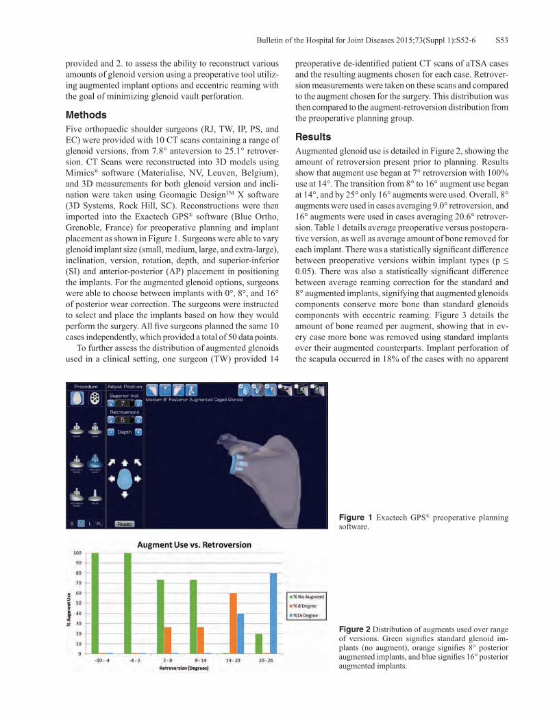
S53Bulletin of the Hospital for Joint Diseases 2015;73(Suppl 1):S52-6
provided and 2. to assess the ability to reconstruct various amounts of glenoid version using a preoperative tool utiliz-ing augmented implant options and eccentric reaming with the goal of minimizing glenoid vault perforation.
MethodsFive orthopaedic shoulder surgeons (RJ, TW, IP, PS, and EC) were provided with 10 CT scans containing a range of glenoid versions, from 7.8° anteversion to 25.1° retrover-sion. CT Scans were reconstructed into 3D models using Mimics® software (Materialise, NV, Leuven, Belgium), and 3D measurements for both glenoid version and incli-nation were taken using Geomagic DesignTM X software (3D Systems, Rock Hill, SC). Reconstructions were then imported into the Exactech GPS® software (Blue Ortho, Grenoble, France) for preoperative planning and implant placement as shown in Figure 1. Surgeons were able to vary glenoid implant size (small, medium, large, and extra-large), inclination, version, rotation, depth, and superior-inferior (SI) and anterior-posterior (AP) placement in positioning the implants. For the augmented glenoid options, surgeons were able to choose between implants with 0°, 8°, and 16° of posterior wear correction. The surgeons were instructed to select and place the implants based on how they would perform the surgery. All five surgeons planned the same 10 cases independently, which provided a total of 50 data points. To further assess the distribution of augmented glenoids used in a clinical setting, one surgeon (TW) provided 14
preoperative de-identified patient CT scans of aTSA cases and the resulting augments chosen for each case. Retrover-sion measurements were taken on these scans and compared to the augment chosen for the surgery. This distribution was then compared to the augment-retroversion distribution from the preoperative planning group.
ResultsAugmented glenoid use is detailed in Figure 2, showing the amount of retroversion present prior to planning. Results show that augment use began at 7° retroversion with 100% use at 14°. The transition from 8° to 16° augment use began at 14°, and by 25° only 16° augments were used. Overall, 8° augments were used in cases averaging 9.0° retroversion, and 16° augments were used in cases averaging 20.6° retrover-sion. Table 1 details average preoperative versus postopera-tive version, as well as average amount of bone removed for each implant. There was a statistically significant difference between preoperative versions within implant types (p ≤ 0.05). There was also a statistically significant difference between average reaming correction for the standard and 8° augmented implants, signifying that augmented glenoids components conserve more bone than standard glenoids components with eccentric reaming. Figure 3 details the amount of bone reamed per augment, showing that in ev-ery case more bone was removed using standard implants over their augmented counterparts. Implant perforation of the scapula occurred in 18% of the cases with no apparent
Figure 1 Exactech GPS® preoperative planning software.
Figure 2 Distribution of augments used over range of versions. Green signifies standard glenoid im-plants (no augment), orange signifies 8° posterior augmented implants, and blue signifies 16° posterior augmented implants.

Bulletin of the Hospital for Joint Diseases 2015;73(Suppl 1):S52-6S54
patterns. In the preoperative patient scan group shown in Figure 4, 8° augments were used in cases averaging 12.3° retroversion, whereas 16° augments were used in cases averaging 20.7° retroversion.
DiscussionImproved glenoid fixation is necessary to improve the long-term success of aTSA. Long-term stability of the glenoid has been shown to be influenced by the preservation of the subchondral plate, compaction of cancellous bone, and mechanical compression of cement.19,20 This can be made possible by careful avoidance of vault perforation. In this study, the goal of the surgeons was to use either a standard
or augmented pegged glenoid with or without eccentric reaming to correct the version as much as possible while trying to avoid penetrating the glenoid vault, as would be done in the operating room. Within this group of surgeons, there appeared to be a con-sistent threshold for the use of augmented glenoids occurring around 9° retroversion. The use of augments was 100% by 14° retroversion. Eight degree augments were used in lower degrees of retroversion, while 16° augments began to be used at 14° of retroversion, and by 20° to 25° only 16° augments were used. It should be observed that the one major outlier in the study occurred in the 25° retroversion case, where one surgeon selected a standard implant instead of the 16° that
Figure 3 Amount reamed per augment over a range of versions. Green signifies standard glenoid implants (no augment), orange signifies 8° posterior augmented implants, and blue signifies 16° posterior augmented implants.
Figure 4 Augments used in actual cases over a range of preoperative versions. Eight degrees posterior aug-ments were used for cases 1 to 9 (shown in orange), and 16° posterior augments were used for cases 10 to 14 (shown in blue).
Table 1 Average Preoperative Versus Postoperative Versions and Degrees Reamed for Each Implant*
Average Preoperative Version Average Postoperative VersionAverage Reaming Correction
(ABS)Standard (No Augment) 3.6° ± 7.6° 0.7° ± 3.5° 6.4° ± 3.5°8° Augment 9.0° ± 3.6° 1.8° ± 2.2° 2.8° ± 2.0°16° Augment 20.7° ± 5.6° 0.7° ± 1.5° 5.4° ± 3.8°P-value Standard vs. 8° 0.0370 0.3451 0.0030P-value Standard vs. 16° 0.0000 0.9726 0.4995P-value 8° vs. 16° 0.0001 0.2681 0.0748
*Retroversion is denoted as positive and anteversion is denoted as negative.

S55Bulletin of the Hospital for Joint Diseases 2015;73(Suppl 1):S52-6
the other four surgeons selected. Of note, was the ability to achieve greater correction at higher degrees of retroversion (> 14°) with augmented implant use combined with some levels of reaming versus eccentric reaming alone (Table 1, Fig. 3). Statistically significantly more reaming was performed with non-augmented glenoid implants versus 8° augmented implants (Table 1, Fig. 3).5,6,10 Multiple studies have shown that approximately 15° to 18° retroversion can be corrected with eccentric reaming before vault perforation occurs.3,19,20 However, this can be implant specific and results in signifi-cant bone loss, possible violation of the subchondral plate, and joint line medialization. The surgeons performing the preoperative planning in this study selected to use augmented implants with various amounts of eccentric reaming to cor-rect larger amounts of retroversion. This theoretically would allow less reaming of the native bone in the clinical setting, possibly preserving the subchondral plate of the glenoid. Findings from the data of 14 actual cases from one surgeon also showed augment use patterns consistent with the vir-tual planning results. At retroversions of approximately 8° to 15°, 8° augmented implants were used. Greater than 15° retroversion was corrected with 16° augments. In total, using a combination of augmented implants and eccentric reaming, the surgeons were able to correct version on average to a postoperative version of ± 1.8°. The preoperative planning data did show that there was an 18% incidence of vault perforation. All were considered slight with only the edge of one peg perforating. This is likely due to the surgeon trying to predict the best case scenario to correct as much version as possible while settling for mini-mal perforation. It must be remembered that this software is used to predict how the surgery will be performed in the actual clinical situation. While not optimal, many surgeons may try to strike a balance by trading slight perforation to correct more version. There are limitations to this study. It is possible that pre-operative planning software does not always truly replicate the clinical situation in the operating room. Difficulties of exposure, patient size, and surgeon experience are not taken into account in this situation. An additional issue is the vari-ance in the ability to preoperatively measure version from a CT scan, as well as intraoperatively estimate version.18 Unlike the preoperative planning software, the vault is fre-quently unable to be visualized 360°. Those patients with larger glenoid retroversion will certainly have more difficult exposures. Also, placement of augmented glenoids can be technically demanding, and some surgeons may not have experience with their use. Despite these weaknesses, this study demonstrates the strengths of the preoperative planning process. This software does allow the surgeon to visualize the glenoid vault in 360°. Implant sizes and augment size use can be predetermined, and the decision can be made of whether or not an aTSA or rTSA would be a better option. If glenoid reconstruction
cannot be performed without significant bone loss or vault perforation, a rTSA could be selected preoperatively, sav-ing valuable time in the OR. The surgeon can also visualize the optimal position of the implant to avoid perforation and have a better understanding of how much reaming can be performed to achieve correction. This preoperative planning combined with an intraoperative navigation system could allow for accurate glenoid reconstruction and implant po-sitioning in the future.
ConclusionThis study demonstrates that surgeons can preoperatively plan glenoid preparation using the ExactechGPS® software and predictably use augmented implants in certain degrees of abnormal version while minimizing glenoid vault perfora-tion. It is recognized that this does not necessarily equate to the exact clinical situation. Future work includes combining the preoperative planning phase with surgeons trying to ex-ecute those plans in the operating room, which could better define the accuracy of the preoperative planning process and patient outcomes.
Conflict of Interest StatementAlexander Greene, B.S., Sandrine Polakovic, M.S., Mat-thew A. Hamilton, Ph.D., are employees of Exactech, Inc., Gainesville, Florida. Richard B. Jones, M.D., Ira M. Par-sons, M.D., Paul Saadi, M.D., Emilie V. Cheung, M.D., are consultants for Exactech, Inc., Gainesville, Florida. Thomas W. Wright, M.D., is a consultant for and receives royalties from Exactech, Inc., Gainesville, Florida.
References1. Walch G, Young AA, Boileau P, et al. Patterns of loosening
of polyethylene keeled glenoid components after shoulder arthroplasty for primary osteoarthritis: results of a multicenter study with more than five years of follow-up. J Bone Joint Surg Am. 2012 Jan 18;94(2):145-50.
2. Verborgt O, De Smedt T, Vanhees M, et al. Accuracy of placement of the glenoid component in reversed shoulder arthroplasty with and without navigation. J Shoulder Elbow Surg. 2011 Jan;20(1):21-6.
3. Ting FS, Poon PC. Perforation tolerance of glenoid implants to abnormal glenoid retroversion, anteversion, and medializa-tion. J Shoulder Elbow Surg. 2013 Feb;22(2):188-96.
4. Jones RB. Addressing glenoid erosion in anatomic total shoulder arthroplasty. Bull Hosp Jt Dis (2013). 2013;71 Suppl 2:S46-50.
5. Shapiro TA, McGarry MH, Gupta R, et al. Biomechanical effects of glenoid retroversion in total shoulder arthroplasty. J Shoulder Elbow Surg. 2007 May-Jun;16(3 Suppl):S90-5.
6. Farron A, Terrier A, Büchler P. Risks of loosening of a pros-thetic glenoid implanted in retroversion. J Shoulder Elbow Surg. 2006 Jul-Aug;15(4):521-6.
7. Iannotti JP, Greeson C, Downing D, et al. Effect of glenoid de-formity on glenoid component placement in primary shoulder arthroplasty. J Shoulder Elbow Surg. 2012 Jan;21(1):48-55.
8. Sears BW, Johnston PS, Ramsey ML, Williams GR.

Bulletin of the Hospital for Joint Diseases 2015;73(Suppl 1):S52-6S56
Glenoid bone loss in primary total shoulder arthroplasty: evaluation and management. J Am Acad Orthop Surg. 2012 Sep;20(9):604-13.
9. Hsu JE, Ricchetti ET, Huffman GR, et al. Addressing glenoid bone deficiency and asymmetric posterior erosion in shoulder arthroplasty. J Shoulder Elbow Surg. 2013 Sep;22(9):1298-308.
10. Roche CP, Diep P, Grey SG, Flurin PH. Biomechanical impact of posterior glenoid wear on anatomic total shoulder arthro-plasty. Bull Hosp Jt Dis (2013). 2013;71 Suppl 2:S5-11.
11. Hermida JC, Flores-Hernandez C, Hoenecke HR, D’Lima DD. Augmented wedge-shaped glenoid component for the correction of glenoid retroversion: a finite element analysis. J Shoulder Elbow Surg. 2014 Mar;23(3):347-54.
12. Kersten AD, Flores-Hernandez C, Hoenecke HR, D’Lima DD. Posterior augmented glenoid designs preserve more bone in biconcave glenoids. J Shoulder Elbow Surg. 2015 Jul;24(7):1135-41.
13. Scalise JJ, Codsi MJ, Bryan J, et al. The influence of three-dimensional computed tomography images of the shoulder in preoperative planning for total shoulder arthroplasty. J Bone Joint Surg Am. 2008 Nov;90(11):2438-45.
14. Edwards TB, Gartsman GM, O’Connor DP, Sarin VK. Safety and utility of computer-aided shoulder arthroplasty. J Shoulder
Elbow Surg. 2008 May-Jun;17(3):503-8.15. Nguyen D, Ferreira LM, Brownhill JR, et al. Design and
development of a computer assisted glenoid implantation technique for shoulder replacement surgery. Comput Aided Surg. 2007 May;12(3):152-9.
16. Kircher J, Wiedemann M, Magosch P, et al. Improved accu-racy of glenoid positioning in total shoulder arthroplasty with intraoperative navigation: a prospective-randomized clinical study. J Shoulder Elbow Surg. 2009 Jul-Aug;18(4):515-20.
17. Nguyen D, Ferreira LM, Brownhill JR, et al. Improved ac-curacy of computer assisted glenoid implantation in total shoulder arthroplasty: an in-vitro randomized controlled trial. J Shoulder Elbow Surg. 2009 Nov-Dec;18(6):907-14.
18. Stübig T, Petri M, Zeckey C, et al. 3D navigated implantation of the glenoid component in reversed shoulder arthroplasty. Feasibility and results in an anatomic study. Int J Med Robot. 2013 Dec;9(4):480-5.
19. Barwood S, Setter KJ, Blaine TA, Bigliani LU. The incidence of early radiolucencies about a pegged glenoid component using cement pressurization. J Shoulder Elbow Surg. 2008 Sep-Oct;17(5):703-8.
20. Young AA, Walch G. Fixation of the glenoid component in total shoulder arthroplasty: what is “modern cementing tech-nique?” J Shoulder Elbow Surg. 2010 Dec;19(8):1129-36.

S57Bulletin of the Hospital for Joint Diseases 2015;73(Suppl 1):S57-62
Roche CP, Staunch C, Hahn W, Grey SG, Flurin P-H, Wright TW, Zuckerman JD. Analysis of glenoid fixation with anatomic total shoulder arthroplasty in an extreme cyclic loading scenario. Bull Hosp Jt Dis. 2015;73(Suppl 1):S57-62.
Abstract
Introduction: ASTM F2028-14 was adopted to recom-mend a cyclic eccentric glenoid edge loading test that simulates the rocking horse loading mechanism beleived to cause aTSA glenoid loosening. While this method accurately simulates that failure mechanism, the recommended 750 N load may not be sufficient to simulate worst-case loading magnitudes, and the recommended 100,000 cycles may not be sufficient to simulate device fatigue-related failure modes. Finally, if greater loading magnitude or a larger number of cycles is performed, the recommended substrate density may not be sufficiently strong to support the elevated loads and cycles. To this end, a new test method is proposed to supplement ASTM F2028-14. Methods: A series of cyclic tests were performed to evaluate the long-term fixation strength of two different hybrid glenoid designs in both low (15 pcf) and high (30 pcf) density polyurethane blocks at elevated loads relative to ASTM F2028-14. To simulate a worst case clinical condition in which the humeral head is superiorly migrated, a cyclic load was applied to the superior glenoid rim to induce a maximum torque on the fixation pegs for three different cyclic loading tests: 1. 1,250 N load for 0.75 M cycles in a 15 pcf block, 2. 1,250 N load for 1.5 M cycles in a 30 pcf block,
Analysis of Glenoid Fixation with Anatomic Total Shoulder Arthroplasty in an Extreme Cyclic Loading Scenario
Christopher P. Roche, M.S., M.B.A., Cameron Staunch, B.S., William Hahn, B.S., Sean G. Grey, M.D., Pierre-Henri Flurin, M.D., Thomas W. Wright, M.D., and Joseph D. Zuckerman, M.D.
and 3. 2,000 N load for 0.65 M cycles in a 30 pcf block. Results: All devices completed cyclic loading without fail-ure, fracture, or loss of fixation regardless of glenoid design, polyurethane density, loading magnitude, or cycle length. No significant difference in post-cyclic displacement was noted between designs in any of the three tests. Post-cyclic radiographs demonstrated that each device maintained fixa-tion with the metal pegs within the bone-substitute blocks with no fatigue related failures. Discussion: These results demonstrate that both cemented hybrid glenoids maintained fixation when tested according to each cyclic loading scenario, with no difference in post-cyclic displacement observed between designs. The lack of fatigue-related failures in these elevated load and high cycle test scenarios are promising, as are the relatively low displacements given the extreme nature of each test. This cyclic loading method is intended to supplement the ASTM F2028-14 standard that adequately simulates the rocking horse loading mechanism but may not adequately simulate the fatigue-related failure modes.
Orthopaedic manufacturers utilize various laboratory testing methodologies to simulate clinical failure modes under worst-case loading conditions to
ensure safety and efficacy and also extrapolate long-term viability of medical devices prior to market release. Vari-ous testing standards and guidance documents have been approved to standardize methodologies and minimize pa-tient risk while facilitating regulatory oversight for product clearances in the various worldwide markets for different implants. These testing standards often recommend worst-case loading conditions, explain how to set-up the test and measure particular variables, and specify minimum loading magnitudes along with minimum sample sizes; however, specific acceptance criteria are not always defined. For designers of anatomic total shoulder arthroplasty (aTSA)
Christopher P. Roche, M.S., M.B.A., Cameron Staunch, B.S., and William Hahn, B.S., are employees of Exactech, Inc., Gainesville, Florida. Sean G. Grey, M.D., Orthopaedic Center of the Rockies, Fort Collins, Colorado. Pierre-Henri Flurin, M.D., Bordeaux-Merignac Clinique du Sport, Merignac, France. Thomas W. Wright, M.D., Department of Orthopaedics and Rehabilitation, University of Florida, Gainesville, Florida. Joseph D. Zuckerman, M.D., Department of Orthopaedic Surgery, Hospital for Joint Diseases, NYU Langone Medical Center, New York, New York. Correspondence: Christopher P. Roche, M.S., M.B.A., Exactech, Inc., 2320 NW 66th Court, Gainesville, Florida 32653; [email protected].

Bulletin of the Hospital for Joint Diseases 2015;73(Suppl 1):S57-62S58
glenoid implants, ASTM F2028-141 was adopted in 2000 to recommend a cyclic eccentric glenoid edge loading test method to simulate the rocking horse loading mechanism.1,2 Aseptic glenoid loosening is well documented in the lit-erature,3-13 and numerous studies have been conducted14-19 using this method to simulate the rocking horse failure mechanism.3-19 While this cyclic eccentric loading method accurately simulates the rocking horse loading mechanism, the mini-mum loading requirements recommended by the testing standard (750 N axial load as the humeral head is translated to ± 90% of the subluxation distance to induce shear and a resultant load between 800 N and 1,000 N depending upon the articular constraint of the tested device)1 may not be suf-ficient to simulate worst-case loading magnitudes. Recent work by Westerhoff and coworkers using an instrumented shoulder prosthesis has demonstrated that joint reaction loads in excess of 1,700 N and 238% body weight (BW) have been reported during common activities of daily living in patients with total shoulder arthroplasty.20-23 Furthermore, while the 100,000 cycles recommended by the standard may be sufficient to assess the fixation of the bone-cement interface, 100,000 cycles may not be sufficient to simulate device fatigue-related failure modes. Over the last decade, there have been a troubling number of reports in the literature of newer glenoid prosthesis designs removed from the mar-ket due to such device fatigue-related failure modes—each of these devices were likely tested to ASTM 2028 prior to release.24-30 Assuming this cyclic eccentric test is performed using a greater loading magnitude or for a longer number of cycles, then the density of the polyurethane substrate utilized should be reevaluated as the specific density recommended by the standard (20 pcf)1,14-16 may not be sufficiently strong to support the elevated loads and cycles. The purpose of this study was to evaluate the long-term fixation strength of two different glenoid implant designs in both low (15 pcf) and high (30 pcf) density polyurethane bone-substitute blocks at elevated loads relative to the ASTM F2028-14 test. To simulate a worst case clinical condition in which the humeral head is superiorly migrated, we applied a cyclic load to the superior rim of each glenoid component inducing a maximum torque on the fixation pegs for each of the following three cyclic loading tests: 1. 1,250 N load for
0.75 M cycles in a low density (15 pcf) block, 2. 1,250 N load for 1.5 M cycles in a high density (30 pcf) block, and 3. 2,000 N load for 0.65 M cycles in a high density (30 pcf) block.
MethodologyTwo different XL hybrid cemented cage glenoid designs were evaluated. The first hybrid cemented cage glenoid design consists of a net compression molded Ultra High Molecular Weight Polyethylene (UHMWPE) articular body assembled in the cleanroom using a pneumatic press to a modular Ti-6Al-4V plasma coated central cage peg and three Ti-6Al-4V peripheral pegs; this device has been used clini-cally with success since 2011 (Fig. 1). The second hybrid cemented cage glenoid design utilized identical material, locking mechanism geometry, and cleanroom assembly process as the first and was released in 2015 with slightly modified metal peg geometry to improve the ease of manu-facturability (Fig. 1). Prior to performing each of the three cyclic tests, each glenoid implant was secured with PMMA bone cement (Ce-mex, Tecres, Inc.) into each aforementioned 76 mm x 57 mm x 48 mm polyurethane bone substitute block (Solid Rigid Foam, Pacific Research Laboratories). The peg pattern was identical for each glenoid design, and the same instrumenta-tion was used to prepare each block. Each glenoid was then positioned in the testing apparatus so that a compression load was applied directly to the superior glenoid edge (Fig. 2). Three cyclic loading tests were performed: 1. 1,250 N load for 0.75 M cycles in a low density (15 pcf) block (N = 3 of each glenoid design), 2. 1,250 N load for 1.5 M cycles in a high density (30 pcf) block (N = 3 of each glenoid design), and 3. 2,000 N load for 0.65 M cycles in a high density (30 pcf) block (N = 4 of each glenoid design). To establish a baseline displacement, a dial gauge quantified the initial displacement associated with each glenoid in each density block as a static load equal to the load applied for each cyclic test was applied to the superior glenoid edge at a rate of 100 N/sec. After this initial displacement was established for each glenoid, the cyclic load was applied in the same location on the superior glenoid edge for a rate of 2 Hz. Following cyclic loading, a dial gauge quantified the post-cyclic displacement in the same method as the pre-
Figure 1 Equinoxe® cage glenoids (Exactech, Inc., Gainesville, FL); Left: “current” design used since 2011 and Right: “new” design used since 2015.

S59Bulletin of the Hospital for Joint Diseases 2015;73(Suppl 1):S57-62
cyclic displacement at a rate of 100 N/sec. After all glenoid implants were cyclically loaded, each device was analyzed for cracks at the implant-cement interface and radiographed.
A two tailed unpaired, Student’s t-test was used to compare mean pre- and post-cyclic displacements, where p < 0.05 determined significance.
ResultsAll devices completed cyclic loading without failure, fracture, or loss of fixation regardless of glenoid design, polyurethane density, loading magnitude, or cycle length. The pre- and post-cyclic displacement data from each of the three cyclic loading tests are presented and compared in Tables 1, 2, and 3, respectively. No statistically significant difference in post-cyclic displacement was noted between designs in any of the three tests. Additionally, Figures 3 and 4 depict representative radiographs of each cage glenoid design after cyclic loading along the superior glenoid rim; these radiographs demonstrate that each device maintained fixation with the metal pegs within the bone-substitute blocks and that no fatigue-related failures occurred with the metal pegs or the UHMWPE locking mechanism.
Discussion The results of this study demonstrate that both new and current cage glenoid designs maintain fixation when tested according to each of the three different cyclic loading sce-narios, with no difference in post-cyclic displacement observed between designs. The lack of fatigue-related failures observed in these elevated load and high cycle test scenarios are promising, as are the relatively low displace-ments given the extreme nature of each test. However, these laboratory results cannot fully predict the long-term clinical
Figure 2 Representative image depicting cyclic loading along the superior glenoid rim when loaded at 2000 N. Superior glenoid rim plastic deformation is evident at these elevated loads.
Figure 3 Representative radiographs of the current cage glenoid design after superior glenoid rim edge loading for 1,250 N for 0.75 M cycles in a low density block (left), 1,250 N for 1.5 M cycles in a high density block (middle), and 2,000 N for 0.65 M cycles in a high density block (right).
Figure 4 Representative radiographs of the new cage glenoid design after superior glenoid rim edge loading for 1,250 N for 0.75 M cycles in a low density block (left), 1,250 N for 1.5 M cycles in a high density block (middle), and 2,000 N for 0.65 M cycles in a high density block (right).

Bulletin of the Hospital for Joint Diseases 2015;73(Suppl 1):S57-62S60
performance of this novel hybrid cemented cage glenoid prosthesis. Similarly, we are not recommending this cyclic test be performed as a substitute for the ASTM F2028-14 standard as that test adequately simulates the rocking horse loading mechanism; instead, this testing methodology is recommended to supplement that testing standard to better characterize the long-term loading and fatigue performance of novel glenoid devices. This cyclic study has some limitations. It utilized two different densities of polyurethane bone substitutes instead of cadaveric or composite scapula bone; this was done to improve uniformity and permit a better comparison between tested glenoid designs. Additionally, this study did not utilize a spherical humeral head to apply the load but rather applied the load through a 5/8 inch machine screw. Due to these ele-vated loads and high cycles, we observed plastic deformation along the superior rim of nearly every glenoid tested at 2,000 N; an improvement to this study would be to apply the load through a humeral head prosthesis to better distribute the pressure and limit the deformation. Additionally, because the cyclic load was only applied along the superior glenoid rim of each component, we did not alternate loading positions between the superior and inferior glenoid as is recommended by the ASTM F2028-14 test method in which the humeral
head is translated ± 90% of the subluxation distance; thus, we did not explicitly simulate the rocking horse mechanism. However, it should be noted that by simulating a superiorly migrated humeral head, we applied the load more than 18 mm superior to the central axis of the glenoid at a signifi-cantly greater load than occurs with the ASTM F2028-14 test to induce a greater moment on the fixation pegs. This 18 mm eccentric loading position is considerably greater than the typical ± 5 mm position which occurs with the ASTM F2028-14 test where the maximum published displacement was less than ± 10 mm. A final limitation is that we did not cyclically load any device to failure; rather, we stopped the test at predefined cycles as described previously. Future work using this cyclic loading method should run glenoids out to failure at different loads in different densi-ties to establish true fatigue curves for different designs and substrates. This test can also be modified to simulate different clinical situations that have previously shown to predispose the glenoid component to a greater risk of loosening, such as implanting the glenoid in superior tilt, retroversion, or partially unsupported as could occur clinically when a surgeon uses a glenoid with partial eccentric reaming in a severely eroded scapula.19,31 Additional testing configura-tions should quantify glenoid fixation when the fixation holes
Table 1 Mean Glenoid Edge Displacements of the New and Current Designs of the Cage Glenoid in the Low Density Polyurethane Bone Substitute when Cyclically Loaded Along the Superior Glenoid Rim at 1,250 N for 0.75 M Cycles
Mean Displacement (mm)(Avg ± Std Dev) Initial Edge Displacement
Post-Cyclic Glenoid Edge Displacement at 0.75 M cycles
Current Cage Glenoid 0.069 ± 0.027 0.109 ± 0.099New Cage Glenoid 0.078 ± 0.037 0.001 ± 0.002P-value 0.7249 0.1316
Table 2 Mean Glenoid Edge Displacements of the New and Current Designs of the Cage Glenoid in the High Density Polyurethane Bone Substitute when Cyclically Loaded Along the Superior Glenoid Rim at 1,250 N for 1.5 M Cycles
Mean Displacement (mm)(Avg ± Std Dev) Initial Edge Displacement
Post-Cyclic Glenoid Edge Displacement at 1.5 M cycles
Current Cage Glenoid 0.080 ± 0.021 0.049 ± 0.029New Cage Glenoid 0.007 ± 0.005 0.008 ± 0.007P-value 0.0041 0.0725
Table 3 Mean Glenoid Edge Displacements of the New and Current Designs of the Cage Glenoid in the High Density Polyurethane Bone Substitute when Cyclically Loaded Along the Superior Glenoid Rim at 2,000 N for 0.65 M Cycles
Mean Displacement (mm)(Avg ± Std Dev) Initial Edge Displacement
Post-Cyclic Glenoid Edge Displacement at 0.65 M cycles
Current Cage Glenoid 0.004 ± 0.005 0.198 ± 0.078New Cage Glenoid 0.011 ± 0.012 0.263 ± 0.073P-value 0.3061 0.2676

S61Bulletin of the Hospital for Joint Diseases 2015;73(Suppl 1):S57-62
are drilled off-axis or malpositioned to create nonuniform cement mantle thicknesses.32,33 Future testing should also elucidate if different viscosities of PMMA bone cement or different methods of cement pressurization impact glenoid fixation.34,35
ConclusionsThis study demonstrates that the novel hybrid cemented cage glenoids tested in three different cyclic loading scenarios maintain fixation without failure or fracture regardless of polyurethane density, loading magnitude, or cycle length. These laboratory results are promising, particularly given the extreme nature of the loading conditions; however, these results are not a substitute for long-term clinical follow-up, which is necessary to demonstrate the long-term viability of this device. The cyclic loading method presented in this study is intended to supplement the ASTM F2028-14 test-ing standard that adequately simulates the rocking horse loading mechanism but may not adequately simulate the fatigue-related failure modes observed with some glenoid designs, which have been documented in the literature over the past decade.24-30
Conflict of Interest StatementSean G. Grey, M.D., Pierre-Henri Flurin, M.D., Thomas W. Wright, M.D., and Joseph D. Zuckerman, M.D. are consul-tants for Exactech, Inc., and receive royalties on products related to this article. Christopher P. Roche, M.S., M.B.A., Cameron Staunch, B.S., and William Hahn, B.S., are em-ployees of Exactech, Inc., Gainesville Florida.
References1. ASTM F2028-14. Standard Test Methods for Dynamic
Evaluation of Glenoid Loosening or Disassociation. West Conshohocken, PA: ASTM International. Available at: http://www.astm.org/Standards/F2028.htm.
2. Franklin JL, Barrett WP, Jackins SE, Matsen FA 3rd. Glenoid loosening in total shoulder arthroplasty. Association with rotator cuff deficiency. J Arthroplasty. 1988;3(1):39-46.
3. Barrett WP, Franklin JL, Jackins SE, et al.Total shoulder arthroplasty. J Bone Joint Surg Am. 1987 Jul;69(6):865-72.
4. Brenner BC, Ferlic DC, Clayton ML, Dennis DA. Survivor-ship of unconstrained total shoulder arthroplasty. J Bone Joint Surg Am. 1989 Oct;71(9):1289-96.
5. Cofield RH. Total shoulder arthroplasty with the Neer pros-thesis. J Bone Joint Surg Am. 1984 Jul;66(6): 899-906.
6. Hawkins RJ, Bell RH, Jallay B. Total shoulder arthroplasty. Clin Orthop Relat Res. 1989 May;(242):188-94.
7. Lazarus MD, Jensen KL, Southworth C, Matsen FA 3rd. The radiographic evaluation of keeled and pegged glenoid component insertion. J Bone Joint Surg Am. 2002 Jul;84-A(7):1174-82.
8. Neer CS 2nd, Watson KC, Stanton FJ. Recent experience in total shoulder replacement. J Bone Joint Surg Am. 1982 Mar;64(3):319-37.
9. Rodosky MW, Bigliani LU. Indications for glenoid resurfac-ing in shoulder arthroplasty. J Shoulder Elbow Surg. 1996
May;5(3):231-48.10. Torchia ME, Cofield RH, Settergren CR. Total shoulder
arthroplasty with the Neer prosthesis: long-term results. J Shoulder Elbow Surg. 1997 Nov-Dec;6(6):495-505.
11. Wirth MA, Rockwood CA Jr. Complications of total shoul-der-replacement arthroplasty. J Bone Joint Surg Am. 1996 Apr;78(4):603-16.
12. Williams GR, Abboud JA. Total shoulder arthroplasty: glenoid component design. J Shoulder Elbow Surg. 2005 Jan-Feb;14(1 Suppl S):122S-128S. Review.
13. Strauss EJ, Roche C, Flurin PH, et al. The glenoid in shoulder arthroplasty. J Shoulder Elbow Surg. 2009 Sep-Oct;18(5):819-33.
14. Anglin C, Wyss UP, Pichora DR. Shoulder prosthesis sublux-ation: theory and experiment. J Shoulder Elbow Surg. 2000 Mar-Apr;9(2):104-14.
15. Anglin C, Wyss UP, Pichora DR. Mechanical testing of shoulder prostheses and recommendations for glenoid design. J Shoulder Elbow Surg. 2000. Jul-Aug;9(4):323-31.
16. Anglin C, Wyss UP, Nyffeler RW, Gerber C. Loosening per-formance of cemented glenoid prosthesis design pairs. Clin Biomech (Bristol, Avon). 2001 Feb;16(2):144-50.
17. Budge MD, Kurdziel MD, Baker KC, Wiater JM. A bio-mechanical analysis of initial fixation options for porous-tantalum-backed glenoid components. J Shoulder Elbow Surg. 2013 May;22(5):709-15.
18. Roche C, Angibaud L, Flurin PH, et al. Glenoid loosening in response to dynamic multi-axis eccentric loading: a compari-son between keeled and pegged designs with an equivalent radial mismatch. Bull Hosp Jt Dis. 2006;63(3-4):88-92.
19. Karelse A, Van Tongel A, Verstraeten T, et al. Rocking-horse phenomenon of the glenoid component: the importance of inclination. J Shoulder Elbow Surg. 2015 Jul;24(7):1142-8.
20. Westerhoff P, Graichen F, Bender A, et al. In vivo measure-ment of shoulder joint loads during activities of daily living. J Biomech. 2009 Aug 25;42(12):1840-9.
21. Bergmann G, Graichen F, Bender A, et al. In vivo gleno-humeral joint loads during forward flexion and abduction. J Biomech. 2011 May 17;44(8):1543-52.
22. Westerhoff P, Graichen F, Bender A, et al. Measurement of shoulder joint loads during wheelchair propulsion measured in vivo. Clin Biomech (Bristol, Avon). 2011 Dec;26(10):982-9.
23. Westerhoff P, Graichen F, Bender A, et al. In vivo measure-ment of shoulder joint loads during walking with crutches. Clin Biomech (Bristol, Avon). 2012 Aug;27(7):711-8.
24. Boileau P, Avidor C, Krishnan SG, et al. Cemented polyeth-ylene versus uncemented metal-backed glenoid components in total shoulder arthroplasty: a prospective, double-blind, randomized study. J Shoulder Elbow Surg. 2002 Jul-Aug;11(4):351-9.
25. Fucentese SF, Costouros JG, Kühnel SP, Gerber C. Total shoulder arthroplasty with an uncemented soft-metal-backed glenoid component. J Shoulder Elbow Surg. 2010 Jun;19(4):624-31.
26. Nho SJ, Nam D, Ala OL, et al. Observations on retrieved gle-noid components from total shoulder arthroplasty. J Shoulder Elbow Surg. 2009 May-Jun;18(3):371-8.
27. Nuttall D, Haines JF, Trail IA. The early migration of a partially cemented fluted pegged glenoid component using radiostereometric analysis. J Shoulder Elbow Surg. 2012
Bulletin of the Hospital for Joint Diseases 2015;73(Suppl 1):S57-62S62
Sep;21(9):1191-6.28. Budge MD, Nolan EM, Heisey MH, et al. Results of total
shoulder arthroplasty with a monoblock porous tantalum glenoid component: a prospective minimum 2-year follow-up study. J Shoulder Elbow Surg. 2013 Apr;22(4):535-41.
29. Montoya F, Magosch P, Scheiderer B, et al. Midterm results of a total shoulder prosthesis fixed with a cementless glenoid component. J Shoulder Elbow Surg. 2013 May;22(5):628-35.
30. Clitherow HD, Frampton CM, Astley TM. Effect of glenoid cementation on total shoulder arthroplasty for degenerative arthritis of the shoulder: a review of the New Zealand National Joint Registry. J Shoulder Elbow Surg. 2014 Jun;23(6):775-81.
31. Hopkins AR, Hansen UN, Amis AA, Emery R. The effects of glenoid component alignment variations on cement mantle stresses in total shoulder arthroplasty. J Shoulder Elbow Surg.
2004 Nov-Dec;13(6):668-75.32. Nyffeler RW, Anglin C, Sheikh R, Gerber C. Influence of
peg design and cement mantle thickness on pull-out strength of glenoid component pegs. J Bone Joint Surg Br. 2003 Jul;85(5):748-52.
33. Terrier A, Büchler P, Farron A. Bone-cement interface of the glenoid component: stress analysis for varying cement thick-ness. Clin Biomech (Bristol, Avon). 2005 Aug;20(7):710-7.
34. Choi T, Horodyski M, Struk A, et al. Incidence of early radiolucent lines after glenoid component insertion for total shoulder arthroplasty: a radiographic study comparing pres-surized and unpressurized cementing techniques. J Shoulder Elbow Surg. 2013 Mar;22(3):403-8.
35. Raiss P, Sowa B, Bruckner T, et al. Pressurisation leads to better cement penetration into the glenoid bone. J Bone Joint Surg Br. 2012 May;94(5):671-7.

S63Bulletin of the Hospital for Joint Diseases 2015;73(Suppl 1):S63-7
Roche C, Diep P, Hamilton M, Wright T, Flurin PH, Zuckerman J, Routman H. Impact of posterior wear on muscle length with reverse shoulder arthro-plasty. Bull Hosp Jt Dis. 2015;73(Suppl 1):S63-7.
Abstract
The use of reverse total shoulder arthroplasty (rTSA) in patients with posterior glenoid wear can be challenging. Implanting a baseplate in the correct version may require significant eccentric reaming, which further medializes the joint line and results in greater rotator cuff muscle shortening. To restore the joint line, bone graft may be required, though it is associated with additional risks. As an alternative solution, augmented glenoid baseplates offer the potential to restore the joint line and improve rotator cuff muscle tensioning without the need for eccentric reaming or supplemental bone graft. To that end, this computer analysis quantifies the rotator cuff muscle length for standard and augmented rTSA when used in a normal and posteriorly worn glenoid. These results demon-strate that shortening of the rotator cuff occurred for both the standard and posterior augmented reverse shoulder designs with additional muscle shortening occurring in scapula with posteriorly worn glenoids. More anatomic rotator cuff muscle tensioning was observed with augmented glenoid baseplates. The use of posterior augmented glenoid baseplates has the potential to improve stability and better restore active internal and external rotation, a current limitation of rTSA. However, clinical follow-up is necessary to confirm these favorable biomechanical results.
The reverse shoulder inverts the anatomic concavi-ties to restore stability to the unstable shoulder and inferiorly and medially shifts the center of rotation
(CoR) to lengthen the abductor moment arms and elongate the deltoid to facilitate improvements in abduction and forward flexion.1-5 However, medially shifting the CoR also translates the humerus medially, which reduces deltoid wrapping to decrease joint stability, and shortens rotator cuff muscles to reduce their ability to generate active internal and external rotation, a current limitation of reverse shoulder arthroplasty.4-8 Despite these limitations, the recent clinical success of reverse shoulder arthroplasty (rTSA) has led to an exponential increase in its usage and also an expansion of its indications, including its use in fractures, revisions, and ever more challenging scenarios such as severe poste-rior glenoid wear.1,9-13 rTSA, as compared to anatomic total shoulder arthroplasty (aTSA), has some potential to have better mid- and long-term outcomes in patients with severe posterior wear because the conforming reverse articulation may provide better joint stability for patients with a poste-rior subluxed humeral head.10 Additionally, the uncemented metal rTSA baseplate with supplemental screw fixation may provide better long-term glenoid fixation in patients with severe posterior wear than a cemented aTSA glenoid due to the need to eccentrically ream the glenoid to correct the deformity.10,14-16 Use of rTSA in patients with eroded glenoids and the technique of eccentric reaming further medializes the joint line and results in additional rotator cuff muscle shortening.18-19 To better restore the joint line in scapulae with eroded glenoids, some surgeons may choose to bone graft the glenoid10,20-25; this, however, is associated with ad-ditional risks, including extra cost, surgical time, and most concerning, the increased risk of glenoid loosening due to graft resorption or fracture.8,10,20-26 As an alternative solution to better conserve glenoid bone, increase prosthesis surface contact area with cortical
Impact of Posterior Wear on Muscle Length with Reverse Shoulder Arthroplasty
Christopher P. Roche, M.S., M.B.A., Phong Diep, B.S., Matthew A. Hamilton, Ph.D., Thomas W. Wright, M.D., Pierre-Henri Flurin, M.D., Joseph D. Zuckerman, M.D., and Howard D. Routman, D.O.
Christopher P. Roche, M.S., M.B.A., Phong Diep, B.S., and Mat-thew A. Hamilton, Ph.D., Exactech, Inc., Gainesville, Florida. Thomas W. Wright, M.D., Department of Orthopaedics and Reha-bilitation, University of Florida, Gainesville, Florida. Pierre-Henri Flurin, M.D., Bordeaux-Merignac Clinique du Sport, Merignac, France. Joseph D. Zuckerman, M.D., Department of Orthopaedic Surgery, Hospital for Joint Diseases, NYU Langone Medical Center, New York, New York. Howard D. Routman, D.O., Atlantis Orthopaedics, Palm Beach Gardens, Florida. Correspondence: Christopher P. Roche, M.S., M.B.A., Exactech, Inc., 2320 NW 66th Court, Gainesville, Florida 32653; [email protected].

Bulletin of the Hospital for Joint Diseases 2015;73(Suppl 1):S63-7S64
bone, and better restore the native joint line when perform-ing rTSA in eroded scapular morphologies,18,19,27 Exactech has developed augmented glenoid baseplates (Fig. 1). These augmented implants, released in early 2011, are implanted with off-axis reaming rather than eccentric reaming and are intended to address superior, posterior, superior-posterior, and medial glenoid wear patterns. The purpose of this com-puter analysis is to quantify the impact of posterior wear on muscle length using standard and posterior augmented reverse shoulder arthroplasty during three different motions: abduction in the scapular plane from 0° to 80° and internal and external rotation with arm at side from 0° to 40° (Fig. 2).
Methods A 3D computer model was developed in Unigraphics (Sie-mens, Inc.) to quantify muscle length during abduction and internal and external rotation using a standard and 8° posterior augmented reverse shoulder (Equinoxe®, Exactech, Inc.) in both a normal and posteriorly worn glenoid. This muscle model has been utilized previously to compare the impact of different prosthesis designs, glenoid bone deformities, humeral implantation techniques, and glenoid implantation techniques on muscle lengths, deltoid wrapping, and muscle moment arms.6-8,19,28-33 Each of these implants were geo-metrically modeled and implanted in a 3D digitized scapula and humerus (Pacific Research, Inc.) so that each glenoid
Figure 1 Equinoxe® baseplates (Exactech, Inc., Gainesville, FL). Top row from left to right: stan-dard baseplate, 8° posterior augment, 10° superior augment; bottom row from left to right: +10 mm extended cage and 10° superior/8° posterior aug-ment baseplate.
Figure 2 Muscle shortening and joint medialization with posterior glenoid wear: standard and posterior augmented rTSA.

S65Bulletin of the Hospital for Joint Diseases 2015;73(Suppl 1):S63-7
baseplate aligned with the inferior glenoid rim as the humeral component was oriented in 20° retroversion. A posterior gle-noid defect was created in the digital scapula by posteriorly shifting the humeral head by 11 mm (until greater tuberosity impingement with acromion), superiorly shifting the humerus by 1.5 mm, and then medially translating the humeral head by 7.0 mm into the scapula. The computer model included seven muscles that were simulated as three lines from origin to insertion: anterior deltoid, middle deltoid, posterior deltoid, subscapularis, infraspinatus, teres major, and teres minor. After assembling each implant in the normal and posteriorly worn scapula, the humeral component was abducted from 0° to 80° in the scapular plane relative to a fixed scapula and then internally and externally rotated from 0° to 40° with the arm at the side (i.e., 0° abduction). Muscle lengths were
measured as the average length of the three lines simulating each muscle at each degree of motion; each muscle length, for each prosthesis, at each angle of motion was compared at the corresponding arm position for the normal shoulder to quantify the percentage change in muscle length relative to the anatomic configuration without posterior wear.
Results The average change in muscle length associated with the standard and posterior augmented reverse shoulder during each of the three motions are presented in Tables 1, 2, and 3. For each of the three motions, both the standard and pos-terior augmented reverse shoulders elongate the anterior, middle, and posterior deltoid and shorten both the internal rotators (subscapularis and teres major) and the external
Table 1 Average Muscle Elongation Relative to Anatomic Shoulder during Scapular Plane Abduction from 0° to 80°Ant.
DeltoidMid
DeltoidPost.
Deltoid Subscapularis Infraspinatus Teres Major Teres Minor 38 mm Standard, No Wear 7.3% 8.2% 6.3% 0.0% -1.6% -1.1% -3.5%38 mm Standard, Posterior Wear 6.9% 7.8% 5.8% 1.1% -2.8% -2.0% -5.3%
38 mm Posterior Augment, No Wear 7.9% 9.0% 6.9% -1.2% -0.5% -0.1% -1.8%
38 mm Posterior Augment, Posterior Wear 8.2% 9.0% 7.1% 1.4% -0.2% 0.1% -1.4%
Table 2 Average Muscle Elongation Relative to Anatomic Shoulder during Internal Rotation from 0° to 40° with Arm at Side
Ant.Deltoid
MidDeltoid
Post.Deltoid Subscapularis Infraspinatus Teres Major Teres Minor
38 mm Standard, No Wear 15.4% 18.4% 14.5% -8.5% -11.7% -10.4% -19.1%38 mm Standard, Posterior Wear 15.4% 18.6% 14.5% -9.6% -12.7% -11.5% -20.8%
38 mm Posterior Augment, No Wear 15.4% 18.5% 14.9% -7.3% -10.6% -9.1% -17.4%
38 mm Posterior Augment, Posterior Wear 15.4% 18.5% 14.9% -7.0% -10.3% -8.8% -17.0%
Table 3 Average Muscle Elongation Relative to Anatomic Shoulder during External Rotation from 0° to 40° with Arm at Side
Ant.Deltoid
MidDeltoid
Post. Deltoid Subscapularis Infraspinatus Teres Major Teres Minor
38 mm Standard, No Wear 16.6% 18.3% 14.3% -8.5% -12.4% -12.3% -22.4%38 mm Standard, Posterior Wear 16.6% 18.5% 14.2% -9.6% -13.7% -13.4% -24.6%
38 mm Posterior Augment, No Wear 16.7% 18.4% 14.7% -7.4% -11.4% -11.0% -20.6%
38 mm Posterior Augment, Posterior Wear 16.7% 18.3% 14.7% -7.1% -11.0% -10.7% -20.1%
Bulletin of the Hospital for Joint Diseases 2015;73(Suppl 1):S63-7S66
rotators (infraspinatus and teres minor) relative to the normal anatomic shoulder. For the standard reverse shoulder, both the internal and external rotators were shortened more by posterior wear. However, the posterior augmented reverse shoulders (regardless of posterior wear) kept the humerus more lateral and were associated with the least shortening of both the internal and external rotators.
DiscussionThe results of this study demonstrate shortening of the rotator cuff for both the standard and posterior augmented reverse shoulder designs, with additional muscle shortening occurring in scapulae with posteriorly worn glenoids. More anatomic rotator cuff muscle tensioning was observed with augmented glenoid baseplates. The observation that the pos-terior augmented baseplate when used with posterior wear achieved more anatomic tensioning than the posterior augment baseplate when used in a normal scapula was unexpected; however, further investigation demonstrated that the posterior augmented baseplate removed less anterior bone to correct posterior wear than did the posterior augmented baseplate when used without wear. Thus, the posterior augmented baseplate when used with posterior wear achieved the most lateral humeral position in this computer model, resulting in greater muscle tensioning of the internal and external rotators. These improvements in muscle tensioning offer the potential to achieve greater stability and increase internal and external rotational motion and strength with augmented rTSA. How-ever, clinical follow-up is required to confirm these favorable biomechanical results. This study was limited by its evaluation of muscle length in only one digital anatomy; future work should evaluate the impact of these designs in both normal and eroded scapula in multiple different anatomies.
ConclusionsThis computer analysis provides new biomechanical insights on the use of rTSA in scapular with posterior wear. Addi-tionally, the use of posterior augmented glenoid baseplates with and without posterior wear resulted in more anatomic tensioning of the rotator cuff muscles; this information is useful to the surgeon to potentially improve stability and restore active internal and external rotation, a current limi-tation of rTSA.
Conflict of Interest StatementThomas W. Wright, M.D., Pierre-Henri Flurin, M.D., and Joseph D. Zuckerman, M.D., are consultants for Exactech, Inc., and receive royalties on products related to this article. Howard D. Routman, D.O., is a consultant for Exactech, Inc. Christopher P. Roche, M.S., M.B.A., Phong Diep, B.S., and Matthew A. Hamilton, Ph.D., are employees of Exactech, Inc., Gainesville, Florida.
References1. Boileau P, Watkinson DJ, Hatzidakis AM, Balg F. Grammont
reverse prosthesis: Design, rationale, and biomechanics. J
Shoulder Elbow Surg. 2005 Jan-Feb;14(1 suppl S):147S-161S.
2. De Wilde LF, Audenaert EA, Berghs BM. Shoulder prostheses treating cuff tear arthropathy: A comparative biomechanical study. J Orthop Res. 2004 Nov;22(6):1222-30.
3. Frankle M, Siegal S, Pupello D, et al.The reverse shoulder prosthesis for glenohumeral arthritis associated with severe rotator cuff deficiency: A minimum two-year follow-up study of sixty patients. J Bone Joint Surg Am. 2005 Aug;87(8):1697-705.
4. Roche C, Crosby L. Kinematics and biomechanics of reverse total shoulder arthroplasty. In: Nicholson GP (ed): Orthopae-dic Knowledge Update: Shoulder and Elbow. Rosemont, IL: American Academy of Orthopaedic Surgeons 2013, pp. 45-54.
5. Roche C, Flurin PH, Wright T, et al. An evaluation of the relationships between reverse shoulder design parameters and range of motion, impingement, and stability. J Shoulder Elbow Surg. 2009 Sep-Oct;18(5):734-41.
6. Roche C, Diep P, Hamilton M, et al. Biomechanical analysis of 3 commercially available reverse shoulder designs in a normal and medially eroded scapula. Presented at the 59th Annual Orthopaedic Research Society Meeting. San Antonio, Texas, January 26-29, 2013.
7. Roche C, Diep P, Hamilton M, et al. Asymmetric Tensioning of the Rotator Cuff by Changing Humeral Retroversion in Reverse Shoulder Arthroplasty. Presented at the 59th Annual Orthopaedic Research Society Meeting. San Antonio, Texas, January 26-29, 2013.
8. Roche CP, Diep P, Hamilton M, et al. Impact of inferior glenoid tilt, humeral retroversion, bone grafting, and de-sign parameters on muscle length and deltoid wrapping in reverse shoulder arthroplasty. Bull Hosp Jt Dis (2013). 2013;71(4):284-93.
9. Boileau P, Watkinson D, Hatzidakis AM, Hovorka I. Neer Award 2005: The Grammont reverse shoulder prosthe-sis: results in cuff tear arthritis, fracture sequelae, and revision arthroplasty. J Shoulder Elbow Surg. 2006 Sep-Oct;15(5):527-40.
10. Mizuno N, Denard PJ, Raiss P, Walch G. Reverse total shoul-der arthroplasty for primary glenohumeral osteoarthritis in patients with a biconcave glenoid. J Bone Joint Surg Am. 2013 Jul 17;95(14):1297-304.
11. Gallusser N, Farron A. Complications of shoulder arthroplasty for osteoarthritis with posterior glenoid wear. Orthop Trau-matol Surg Res. 2014 Sep;100(5):503-8.
12. Stechel A, Fuhrmann U, Irlenbusch L, et al. Reversed shoulder arthroplasty in cuff tear arthritis, fracture sequelae, and revi-sion arthroplasty. Acta Orthop. 2010 Jun;81(3):367-72.
13. Jiang JJ, Toor AS, Shi LL, Koh JL. Analysis of perioperative complications in patients after total shoulder arthroplasty and reverse total shoulder arthroplasty. J Shoulder Elbow Surg. 2014 Dec;23(12):1852-9.
14. Farron A, Terrier A, Büchler P. Risks of loosening of a pros-thetic glenoid implanted in retroversion. J Shoulder Elbow Surg. 2006 Jul-Aug;15(4):521-6.
15. Gillespie R. Lyons R, Lazarus M. Eccentric reaming in total shoulder arthroplasty: a cadaveric study. Orthopedics. 2009 Jan;32(1):21.
16. Clavert P, Millett PJ, Warner JJ. Glenoid resurfacing: what are the limits to asymmetric reaming for posterior erosion? J Shoulder Elbow Surg. 2007 Nov-Dec;16(6):843-8.

S67Bulletin of the Hospital for Joint Diseases 2015;73(Suppl 1):S63-7
17. Nowak DD, Bahu MJ, Gardner TR, et al. Simulation of sur-gical glenoid resurfacing using three-dimensional computed tomography of the arthritic glenohumeral joint: the amount of glenoid retroversion that can be corrected. J Shoulder Elbow Surg. 2009. Sep-Oct;18(5):680-8.
18. Roche CP, Stroud NJ, Martin BL, et al. Achieving fixation in glenoids with superior wear using reverse shoulder arthro-plasty. J Shoulder Elbow Surg. 2013 Dec;22(12):1695-701.
19. Roche CP, Diep P, Grey SG, Flurin PH. Biomechanical impact of posterior glenoid wear on anatomic total shoulder arthro-plasty. Bull Hosp Jt Dis (2013). 2013;71 Suppl 2:S5-11.
20. Neyton L, Walch G, Nové-Josserand L, Edwards TB. Glenoid corticocancellous bone grafting after glenoid component removal in the treatment of glenoid loosening. J Shoulder Elbow Surg. 2006 Mar-Apr;15(2):173-9.
21. Neyton L, Boileau P, Nové-Josserand L, et al. Glenoid bone grafting with a reverse design prosthesis. J Shoulder Elbow Surg. 2007 May-Jun;16(3 Suppl):S71-8.
22. Norris TR, Kelly JD, Humphrey CS. Management of glenoid bone defects in revision shoulder arthroplasty: A new applica-tion of the reverse total shoulder prosthesis. Tech Shoulder Elbow Surg 2007;8(1):37-46.
23. Bateman E, Donald SM. Reconstruction of massive uncon-tained glenoid defects using a combined autograft-allograft construct with reverse shoulder arthroplasty: preliminary results. J Shoulder Elbow Surg. 2012 Jul;21(7):925-34.
24. Melis B, Bonnevialle N, Neyton L, et al. Glenoid loosening and failure in anatomical total shoulder arthroplasty: is revi-sion with a reverse shoulder arthroplasty a reliable option? J Shoulder Elbow Surg. 2012 Mar;21(3):342-9.
25. Boileau P, Moineau G, Roussanne Y, O’Shea K. Bony increased-offset reversed shoulder arthroplasty: minimizing
scapular impingement while maximizing glenoid fixation. Clin Orthop Relat Res. 2011 Sep;469(9):2558-67.
26. Stroud N, DiPaola MJ, Flurin PH, Roche CP. Reverse shoulder glenoid loosening: an evaluation of the initial fixation associ-ated with six different reverse shoulder designs. Bull Hosp Jt Dis (2013). 2013;71 Suppl 2:S12-7.
27. Roche CP, Diep P, Hamilton MA, et al. Comparison of bone removed with reverse total shoulder arthroplasty. Bull Hosp Jt Dis (2013). 2013;71 Suppl 2:S36-40.
28. Hamilton MA, Roche CP, Diep P, et al. Effect of prosthesis design on muscle length and moment arms in reverse total shoulder arthroplasty. Bull Hosp Jt Dis (2013). 2013;71 Suppl 2:S31-5.
29. Hamilton M, Diep P, Roche C, et al. The effect of reverse shoulder design on the moment arms of muscles surrounding the joint during external rotation. Presented at the 59th Annual Orthopaedic Research Society Meeting. San Antonio, Texas, January 26-29, 2013.
30. Hamilton M, Diep P, Roche C, et al. How does reverse shoul-der design affect rotator muscle moment arms? Presented at the 8th Combined Meeting of the Orthopaedic Research Societies, Venice, Italy, October 13-16, 2013.
31. Hamilton M, Diep P, Roche C, et al. The effect of muscle wrapping on modeling of reverse shoulders. Presented at the 8th Combined Meeting of the Orthopaedic Research Societies, Venice, Italy, October 13-16, 2013.
32. Roche CP, Hamilton MA, Diep P, et al. Design rationale for a posterior/superior offset reverse shoulder prosthesis. Bull Hosp Jt Dis (2013). 2013;71 Suppl 2:S18-24.
33. Hamilton MA, Diep P, Roche C, et al. Effect of reverse shoul-der design philosophy on muscle moment arms. J Orthop Res. 2015 Apr;33(4):605-13.
Bulletin of the Hospital for Joint Diseases 2015;73(Suppl 1):S68-78S68
Jacobson R, Gilot G, Hamilton M, Greene A, Flurin P-H, Wright T, Zuckerman JD, Roche CP. Glenohumeral anatomic study: a comparison of male and female shoulders with similar average age and BMI. Bull Hosp Jt Dis. 2015;73(Suppl 1):S68-78.
Abstract
Introduction: Numerous anatomic studies of the shoul-der have quantified the size, shape, and variability of either the humerus or scapula individually. However, few have attempted to quantify the relationship of the humerus to the scapula to better understand the spatial variation of these bones in both male and female shoulders. Methods: Seventy-four cadaveric shoulder CT scans (37 males and 37 females with statistically equivalent age and BMI) were reconstructed using Mimics® to create 3D models of the humerus and scapula. After 3D reconstruc-tion, each CT bone model was analyzed in Rapidform® to quantify the morphology of the humerus, scapula, and the spatial relationship between the two to better understand the role of gender on the morphological variability of the glenohumeral joint. Results: Spatial glenohumeral relationships of male shoulders were significantly larger than female shoulders in 13 of 16 measurements; morphology of male humeri were significantly larger than female humeri in 17 of 24 measurements, and scapula and glenoid morphology
of male shoulders were significantly larger than female scapula and glenoids in 11 of 22 measurements. Discussion: Numerous significant gender differences in spatial relationships and morphology were identified in this anatomic study of the glenohumeral joint. An improved understanding of these observed binomial distributions has utility for shoulder arthroplasty prosthesis design, computer navigation, and may also be useful to the orthopaedic sur-geon during surgical preoperative planning.
Numerous anatomic studies of the shoulder have previously quantified the size, shape, and variability of either the humerus1-7 or scapula2,4,7-17 individu-
ally, and some have assessed the variability as a function of gender.6,7,11,14,15 However, few studies4,7 have attempted to quantify the relationship of the humerus to the scapula to better understand the spatial variation of these bones in both male and female shoulders. An improved understand-ing of the variability in this spatial relationship may have many applications related to shoulder arthroplasty prosthesis design, computer navigation, and surgical implantation techniques (as many complications associated with shoulder arthroplasty involve patient-specific factors). Additional considerations should be given to gender effects since the majority of shoulder arthroplasty is performed in females, with females being recipients for reverse shoulder arthro-plasty (rTSA) approximately 65% of the time. To that end, we conducted an anatomic study on 74 3D CT reconstruc-tions of the shoulder (37 males and 37 females) to quantify the morphology of the humerus, scapula, and the spatial relationship between the two to better understand the role of gender on the anatomic variability of the glenohumeral joint.
Materials and MethodsSeventy-four cadaveric shoulder CT scans, 37 males (76.7 ± 8.8 years; BMI = 23.7 ± 6.3) and 37 females (78.1 ± 10.9
Glenohumeral Anatomic StudyA Comparison of Male and Female Shoulders with Similar Average Age and BMI
Amanda Jacobson, B.S., Gregory J. Gilot, M.D., Matthew A. Hamilton, Ph.D., Alexander Greene, B.S., Pierre-Henri Flurin, M.D., Thomas W. Wright, M.D., Joseph D. Zuckerman, M.D., and Christopher P. Roche, M.S., M.B.A.
Amanda Jacobson, B.S., Matthew A. Hamilton, Ph.D., Alexander Greene, B.S., and Christopher P. Roche, M.S., M.B.A., Exactech, Inc., Gainesville, Florida. Gregory J. Gilot, M.D., Chairman, Department of Orthopaedic Surgery and Director, Orthopaedic and Rheumatologic Center, Cleveland Clinic Florida, Weston, Florida. Pierre-Henri Flurin, M.D., Bordeaux-Merignac Clinique du Sport, Merignac, France. Thomas W. Wright, M.D., Depart-ment of Orthopaedics and Rehabilitation, University of Florida, Gainesville, Florida. Joseph D. Zuckerman, M.D., Department of Orthopaedic Surgery, Hospital for Joint Diseases, NYU Langone Medical Center, New York, New York. Correspondence: Christopher P. Roche, M.S., M.B.A., Exactech, Inc., 2320 NW 66th Court, Gainesville, Florida 32653; [email protected].

S69Bulletin of the Hospital for Joint Diseases 2015;73(Suppl 1):S68-78
years; BMI = 21.3 ± 5.8) were reconstructed using Mimics® (Materialise NV, Leuven, Belgium) to create 3D models of the humerus and scapula. CTs were taken with 0.5 mm slice thickness. After 3D reconstruction, each CT bone model was analyzed in Rapidform® (3D Systems) to quantify variations
in morphology between males and females with statistically equivalent age (p = 0.59) and BMI (p = 0.09). Differences in morphology between males and females were also compared relative to each humeral head diameter in order to normalize the parameters for size. Measurement reproducibility was
Table 1 Comparison of Average Glenohumeral Joint Scapular Plane Measurements: Female Versus Male
Anatomic Parameter (mm unless noted)All
Shoulders Female MaleP-value
(Male vs. Female)Dimension 1: Base of Coracoid to Lateral Greater Tuberosity 56.6 ± 5.1 53.4 ± 4.4 59.8 ± 3.7 < 0.0001Dimension 2: Center of Glenoid to Lateral Greater Tuberosity 55.1 ± 5.3 51.3 ± 3.3 59.0 ± 3.9 < 0.0001Dimension 3: Lateral Coracoid to Lateral Greater Tuberosity 39.4 ± 5.2 37.4 ± 5.1 41.5 ± 4.5 0.0006Dimension 4: Lateral Acromion to Lateral Greater Tuberosity 25.2 ± 4.9 23.3 ± 3.6 27.1 ± 5.3 0.0005Dimension 5: Center of Glenoid to Lateral Coracoid 15.7 ± 4.6 13.7 ± 3.9 17.6 ± 4.5 0.0002Dimension 6: Lateral Acromion to Top of Greater Tuberosity 18.6 ± 5.1 17.3 ± 3.9 19.9 ± 5.9 0.0295Dimension 7: Lateral Acromion to Lateral Greater Tuberosity 38.2 ± 6.3 35.3 ± 4.6 41.2 ± 6.5 < 0.0001Dimension 8: Humeral Head Center to Lateral Coracoid 14.7 ± 6.4 12.4 ± 4.8 17.1 ± 6.9 0.0010Dimension 9: Humeral Head Center to Lateral Acromion 33.9 ± 4.5 31.2 ± 2.3 36.6 ± 4.5 < 0.0001Dimension 10: Angle between Acromion and Top of Greater Tuberosity (degrees)
54.8 ± 7.7° 56.0 ± 6.5° 53.6 ± 8.7° 0.1885
Dimension 11: Lateral Acromion to Top of Greater Tuberosity 23.3 ± 5.6 21.6 ± 3.9 24.9 ± 6.4 0.0088Dimension 12: Humeral Head Center to Lateral Greater Tuberosity 5.4 ± 5.0 5.1 ± 5.0 5.7 ± 5.0 0.5976Dimension 13: Humeral Head Center to Top of Greater Tuberosity 20.6 ± 3.1 19.0 ± 2.5 22.2 ± 2.8 < 0.0001Dimension 14: Deltoid Tuberosity to Lateral Greater Tuberosity 12.2 ± 4.9 11.8 ± 4.8 12.7 ± 5.1 0.4175Dimension 15: Center of Glenoid to Lateral Acromion 29.9 ± 4.4 28.0 ± 3.1 31.9 ± 4.7 < 0.0001Dimension 16: Middle Deltoid Abductor Moment Arm 27.5 ± 2.7 25.7 ± 1.6 29.2 ± 2.4 < 0.0001
Figure 1 CT reconstructions of female (pink/blue) and male (green/yellow) shoulders.

Bulletin of the Hospital for Joint Diseases 2015;73(Suppl 1):S68-78S70
determined to be ± 1.0 mm for linear parameters and ± 1.0° for angular parameters. A Student’s two-tailed, unpaired t-test was used to identify differences between male and female measurements for the glenohumeral joint relation-
ships, the humeral morphology, and the scapula and glenoid morphology, where p < 0.05 denoted a significant difference. Linear correlations were also performed between all joint measurements.
Figure 2 Glenohumeral joint relationship spatial measurements.
Figure 3 Humeral measurements 1. Figure 4 Humeral measurements 2.

S71Bulletin of the Hospital for Joint Diseases 2015;73(Suppl 1):S68-78
To quantify the spatial glenohumeral joint relationships, each reconstructed CT bone model was oriented with the humerus in 10° of abduction in the scapular plane and po-sitioned to permit 3 mm space between the humeral head and glenoid to account for the thickness of the cartilage and labrum (Fig. 1). As described in Figure 2 and Table 1, 16 measurements were obtained to quantify the position of the humerus relative to the scapula in the scapular plane. These scapular plane spatial measurements were selected because they can be visualized and measured from anterior-posterior (AP) radiographs and therefore may be viable as preopera-tive planning parameters. The coefficient of variation of each measurement was quantified to assess the viability of each measurement to be taken from AP radiographs. As described in Figures 3, 4, and 5, and Table 2, 24 measurements were obtained to quantify the morphology of the humerus independent of the scapula. The humeral shaft outer diameter (OD) and humeral intramedullary (IM) canal diameter were measured using a best fit circle at four different heights (75 mm, 150 mm, and 225 mm from the humeral head and also at the deltoid tuberosity). The linear offset between these best fit circles was also quantified but
not depicted in the figures. The humeral head diameter was measured with a best fit sphere; the humeral head thickness was measured from a plane defining the anatomic neck, and the articular surface area was calculated using this sphere diameter and associated thickness. The medial, posterior, and total offset of the humeral head center were measured relative to the IM axis; the anterior and posterior distances from the humeral head center were also measured for the lesser and greater tuberosities, respectively. The humeral head neck angle was measured relative to the IM axis, and the humeral head retroversion was measured relative to the epicondylar axis. As described in Figures 6 through 9 and Table 3, 22 mea-surements were obtained to quantify the morphology of the scapula and glenoid independent of the humerus. Glenoid height was measured linearly along the superior-inferior (SI) glenoid axis. Glenoid width was measured linearly at the upper third and lower third of the glenoid as a line perpen-dicular to that SI glenoid axis; ratios between glenoid height and width were also calculated. The glenoid articular surface area was measured digitally from the selected glenoid face. Glenoid articular curvature was measured with a best-fit
Table 2 Comparison of Average Humeral Measurements: Female Versus Male
Anatomic Parameter (mm unless noted) All Humeri Female MaleP-value
(Male vs. Female)Dimension 1: HH Diameter 46.8 ± 4.2 43.7 ± 2.3 49.9 ± 3.3 < 0.0001Dimension 2: HH Thickness 19.5 ± 2.5 17.9 ± 1.9 21.0 ± 2.0 < 0.0001Dimension 3: Distance from top of HH to Deltoid Insertion 139.1 ± 9.9 134.2 ± 7.6 143.9 ± 9.6 < 0.0001Dimension 4: HH Neck Angle 134.5 ± 5.1 134.3 ± 5.2 134.6 ± 4.9 0.8069Dimension 5: HH Medial Offset 8.1 ± 3.3 7.6 ± 3.0 8.7 ± 3.6 0.1423Dimension 6: HH Posterior Offset 3.2 ± 2.3 2.5 ± 2.0 3.8 ± 2.4 0.0164Dimension 7: Total HH Offset 9.0 ± 3.4 8.3 ± 2.8 9.7 ± 3.8 0.0709Dimension 8: Center of HH to Lesser Tuberosity 25.3 ± 3.5 22.9 ± 2.7 27.8 ± 2.2 < 0.0001Dimension 9: Center of HH to Greater Tuberosity 22.4 ± 2.7 21.1 ± 2.5 23.8 ± 2.1 < 0.0001Dimension 10: HH Retroversion (degrees) 26.7 ± 12.1° 29.4 ± 11.1° 24.1 ± 12.7° 0.0610Dimension 11: Humeral IM Diameter (75 mm) 14.0 ± 3.0 11.9 ± 2.1 16.2 ± 2.1 < 0.0001Dimension 12: Humeral Outer Diameter (75 mm) 23.1 ± 3.5 20.4 ± 2.2 25.8 ± 2.4 < 0.0001Dimension 13: Humeral IM Diameter (Deltoid Insertion) 10.6 ± 2.4 9.4 ± 2.0 11.7 ± 2.1 < 0.0001Dimension 14: Humeral Outer Diameter (Deltoid Insertion) 21.4 ± 2.9 19.2 ± 1.8 23.5 ± 1.9 < 0.0001Dimension 15: Humeral IM Diameter (150 mm) 10.4 ± 2.4 9.2 ± 1.8 11.5 ± 2.4 < 0.0001Dimension 16: Humeral Outer Diameter (150 mm) 21.4 ± 2.9 19.2 ± 1.9 23.7 ± 1.9 < 0.0001Dimension 17: Humeral IM Diameter (225 mm) 9.1 ± 1.9 8.5 ± 1.6 9.8 ± 1.9 0.0030Dimension 18: Humeral Outer Diameter (225 mm) 19.2 ± 2.6 17.1 ± 1.7 21.2 ± 1.6 < 0.0001Dimension 19: Humerus Length 321.1 ± 21.3 307.1 ± 15.8 335.1 ± 16.3 < 0.0001HH Articular Surface Area (mm2) 3465 ± 633 3003 ± 329 3926 ± 518 < 0.0001Offset Between IM and Outer Diameters (Deltoid Tuberosity)
0.9 ± 0.5 0.8 ± 0.5 1.0 ± 0.5 0.1925
Offset Between IM and Outer Diameters (75 mm) 0.8 ± 0.5 0.8 ± 0.4 0.9 ± 0.5 0.2683Offset Between IM and Outer Diameters (150 mm) 0.9 ± 0.6 0.8 ± 0.4 1.1 ± 0.7 0.0401Offset Between IM and Outer Diameters (225 mm) 0.6 ± 0.3 0.5 ± 0.3 0.6 ± 0.3 0.0659

Bulletin of the Hospital for Joint Diseases 2015;73(Suppl 1):S68-78S72
sphere to the selected glenoid face. Glenoid neck length was measured linearly along the scapular plane between the inferior glenoid rim and the infraglenoid tubercule. Scapular neck angle was measured as the angular difference between the scapular neck and the SI glenoid axis. Glenoid version was measured as the angular difference between the anterior-posterior (AP) glenoid axis and the long axis of the scapula
(defined by the line connecting the center of the glenoid and the intersection of the scapular spine and scapular body at the medial border); greater than 90° indicates retroversion. Similarly, glenoid inclination was measured as the angle between the long axis of the scapula and the SI glenoid axis; greater than 90° indicates inclination. Acromion length was measured linearly along the lateral border between its most anterior and posterior points. Acromion thickness was measured at two different locations: 1. SI width in the middle of the lateral border and 2. AP width at its intersection with the scapular spine. The posterior-superior (PS) acromion-glenoid distance was measured linearly in the AP direction between the most anterior point of the lateral border and the SI glenoid axis. The posterior-inferior (PI) acromion-glenoid distance was measured linearly in the AP direction between the most posterior point of the lateral border and SI glenoid axis. The lateral acromion-glenoid distance was measured linearly in the medial-lateral (ML) direction between the most lateral point of the lateral boarder and the center of the glenoid. The acromial-glenoid angle was measured as the angular difference between the lateral border and the SI glenoid axis. The coracoid tip-glenoid distance was mea-sured linearly in the ML direction between the most lateral point of the coracoid to the center of the glenoid. Finally, the coracoid base-glenoid distance was measured linearly in the ML direction between the most lateral aspect of the coracoid base to the center of the glenoid.
ResultsAs described in Table 1, spatial glenohumeral relation-ships of male shoulders were significantly larger than that of female shoulders in 13 of 16 measurements. However, when each of the 16 glenohumeral relationship measure-ments were normalized by the humeral head diameter, only glenohumeral dimensions 8 and 10 were observed to be significantly different between male and female shoulders (with dimension 8 for male shoulders being significantly larger than female shoulders, and dimension 10 for female shoulders being significantly larger than male shoulders). These normalized measurements suggest that coracoid morphology is highly variable according to gender. Ad-ditionally, measurements 1 to 3, 9, 10, 13, 15, and 16 were all found to have coefficients of variations (COV) less than 15%, with dimensions 1, 2, and 16 having a COV between 6% and 8% for both male and female shoulders, suggesting that these scapular plane measurements are reliable and can be measured on AP radiographs. As described in Table 2, measurements of male humeri were significantly larger than that of female humeri in 17 of 24 measurements. Male humeri were associated with sig-nificantly larger and thicker humeral heads that were more offset (particularly in the posterior direction) than female humeri. Additionally, male humeri were associated with significantly more anterior shift of the lesser tuberosity and significantly more posterior shift of the greater tuberosity. The male humeri were also observed to be significantly
Figure 5 Humeral measurements 3.

S73Bulletin of the Hospital for Joint Diseases 2015;73(Suppl 1):S68-78
longer, with larger OD and IM diameters at all four resection heights. However, when each measurement was normalized by the humeral head diameter, only humeral dimensions 8, 11 to 14, 16, 18, and humeral head articular surface area were observed to be significantly larger for male humeri than female humeri. When comparing the normalized measure-ments, humeral dimensions 3, 4, 10, and 19 were observed to
be significantly larger for female humeri than male humeri. As described in Table 3, scapula and glenoid measure-ments for male shoulders were significantly larger than that of female shoulders in 11 of 22 measurements. Male scapula were associated with significantly larger and wider glenoids than female scapula, with male glenoids having significantly larger articular surface areas. Additionally, male acromions
Figure 6 Scapula measurements 1.
Figure 7 Scapula measurements 2. Figure 8 Scapula measurements 3.

Bulletin of the Hospital for Joint Diseases 2015;73(Suppl 1):S68-78S74
were observed to be significantly thicker (both SI and AP) and longer than female acromions, with male acromions hav-ing significantly larger PI acromion-glenoid distances and lateral acromion-glenoid distances. Finally, male coracoids were observed to be longer than females, with males having longer coracoid tip-glenoid distances. However, when each measurement was normalized by the humeral head diameter, only scapula and glenoid dimensions 9, 11, and the glenoid articular surface area were observed to be significantly larger for male scapula than female scapula. When comparing the normalized measurements, scapula and glenoid dimensions 5, 6, 16, 18, 19, and both glenoid height and width ratios were observed to be significantly larger for female scapula than male scapula. Considering only linear correlations greater than 0.9 between the direct (non-normalized) measurements, both males (r = 0.99) and females (r = 0.99) had a positive cor-relation between humeral head diameter (humeral dimension #1) and humeral head articular surface area. Additionally, both males (r = 0.97) and females (r = 0.95) had a positive correlation between humeral head medial offset (humeral dimension #5) and total humeral head offset (humeral dimen-sion #7). Both males (r = 0.95) and females (r = 0.92) also had a positive correlation between the humeral intramedul-
Table 3 Comparison of Average Scapular Measurements: Female Versus Male
Anatomic Parameter (all values mm unless noted) All Scapula Female Male
P-value (Male vs. Female)
Dimension 1: Glenoid Neck Length 9.5 ± 2.8 9.2 ± 2.6 9.8 ± 3.0 0.2989Dimension 2: Coracoid Tip-Glenoid Distance 16.4 ± 4.7 14.6 ± 3.7 18.2 ± 4.9 0.0006Dimension 3: Lateral Acromion-Glenoid Distance 29.1 ± 4.8 27.5 ± 2.9 30.7 ± 5.8 0.0038Dimension 4: Glenoid Articular Curvature, Radius 40.7 ± 13.4 39.5 ± 17.4 41.8 ± 7.6 0.4601Dimension 5: Scapular Neck Angle (degrees) 116.1 ± 12.0° 114.2 ± 10.8° 118.1 ± 12.9° 0.1631Dimension 6: Glenoid Inclination (degrees) 96.4 ± 5.2° 97.0 ± 5.5° 95.8 ± 4.9° 0.3253Dimension 7: Coracoid Base-Glenoid Distance 1.1 ± 2.9 1.6 ± 1.7 0.6 ± 3.6 0.1590Dimension 8: Glenoid Height 38.1 ± 4.5 35.1 ± 2.5 41.1 ± 4.1 < 0.0001Dimension 9: Glenoid Upper Width 23.6 ± 4.2 21.9 ± 3.7 25.3 ± 4.0 0.0003Dimension 10: Glenoid Lower Width 29.6 ± 4.0 27.0 ± 2.7 32.1 ± 3.4 < 0.0001Dimension 11: Acromion Thickness (AP width at spine) 14.4 ± 2.9 12.5 ± 2.2 16.2 ± 2.3 < 0.0001Dimension 12: Acromion Length 49.2 ± 5.6 45.4 ± 4.5 53.1 ± 3.5 < 0.0001Dimension 13: Acromion Thickness (SI width lateral border) 10.6 ± 3.9 9.2 ± 1.2 11.9 ± 5.1 0.0022Dimension 14: PI Acromion-Glenoid Distance 42.7 ± 5.1 39.5 ± 3.4 45.9 ± 4.5 < 0.0001Dimension 15: Distance from Acromial Plane to Center of Glenoid 37.6 ± 3.8 35.2 ± 2.8 40.1 ± 3.1 < 0.0001Dimension 16: Acromial-Glenoid Angle (degrees) 53.2 ± 10.5° 53.3 ± 9.2° 53.0 ± 11.8° 0.8864Dimension 17: PS Acromion-Glenoid Distance 3.4 ± 4.9 3.1 ± 4.4 3.7 ± 5.5 0.6105Dimension 18: Glenoid Version (degrees) 96.2 ± 5.5° 95.0 ± 4.0° 97.4 ± 6.6° 0.0614Dimension 19: Fulcrum Axis (degrees) 89.9 ± 5.3° 89.5 ± 4.5° 90.3 ± 6.1° 0.5373Glenoid Height/Upper Width Ratio 1.64 ± 0.21 1.63 ± 0.20 1.65 ± 0.23 0.6443Glenoid Height/Lower Width Ratio 1.29 ± 0.10 1.30 ± 0.09 1.29 ± 0.12 0.4728Glenoid Articular Surface Area (mm2) 814 ± 209 666 ± 106 962 ± 179 < 0.0001
Figure 9 Scapula measurements 4.
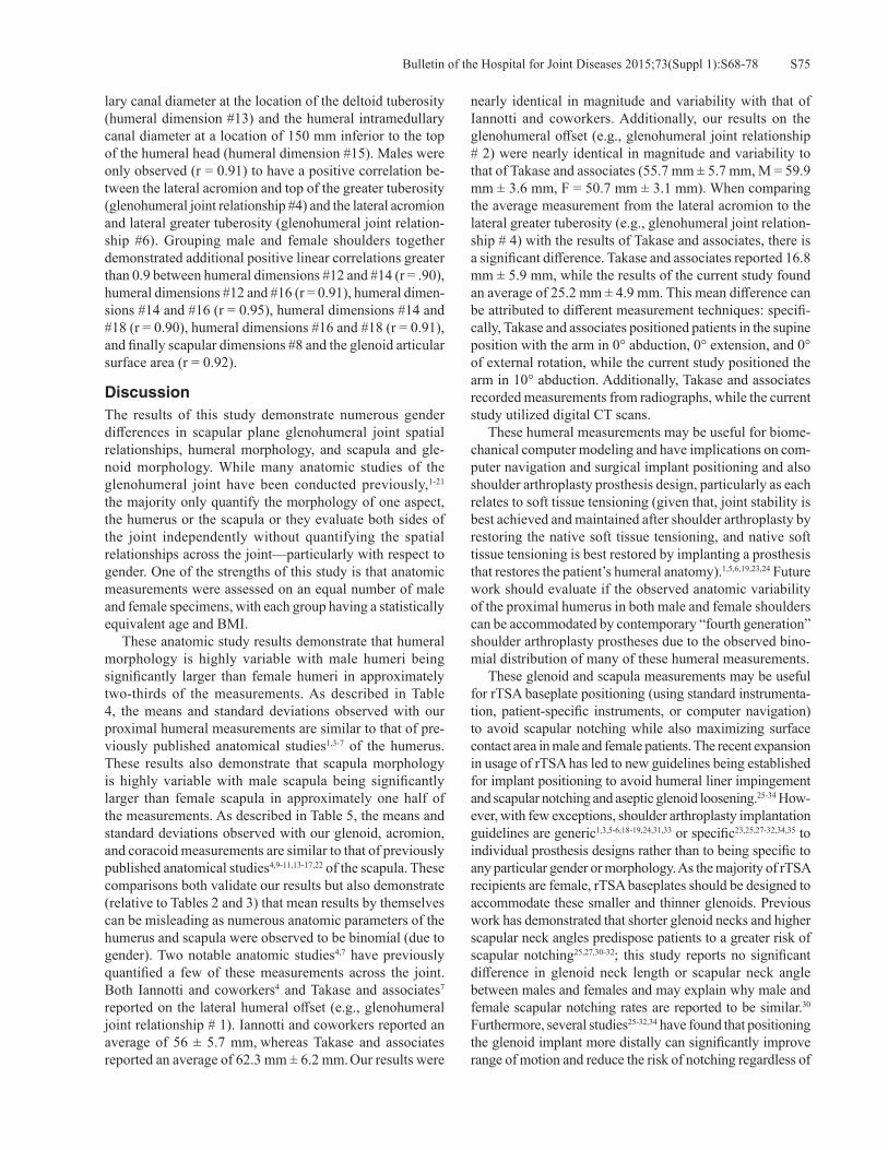
S75Bulletin of the Hospital for Joint Diseases 2015;73(Suppl 1):S68-78
lary canal diameter at the location of the deltoid tuberosity (humeral dimension #13) and the humeral intramedullary canal diameter at a location of 150 mm inferior to the top of the humeral head (humeral dimension #15). Males were only observed (r = 0.91) to have a positive correlation be-tween the lateral acromion and top of the greater tuberosity (glenohumeral joint relationship #4) and the lateral acromion and lateral greater tuberosity (glenohumeral joint relation-ship #6). Grouping male and female shoulders together demonstrated additional positive linear correlations greater than 0.9 between humeral dimensions #12 and #14 (r = .90), humeral dimensions #12 and #16 (r = 0.91), humeral dimen-sions #14 and #16 (r = 0.95), humeral dimensions #14 and #18 (r = 0.90), humeral dimensions #16 and #18 (r = 0.91), and finally scapular dimensions #8 and the glenoid articular surface area (r = 0.92).
Discussion The results of this study demonstrate numerous gender differences in scapular plane glenohumeral joint spatial relationships, humeral morphology, and scapula and gle-noid morphology. While many anatomic studies of the glenohumeral joint have been conducted previously,1-21 the majority only quantify the morphology of one aspect, the humerus or the scapula or they evaluate both sides of the joint independently without quantifying the spatial relationships across the joint—particularly with respect to gender. One of the strengths of this study is that anatomic measurements were assessed on an equal number of male and female specimens, with each group having a statistically equivalent age and BMI. These anatomic study results demonstrate that humeral morphology is highly variable with male humeri being significantly larger than female humeri in approximately two-thirds of the measurements. As described in Table 4, the means and standard deviations observed with our proximal humeral measurements are similar to that of pre-viously published anatomical studies1,3-7 of the humerus. These results also demonstrate that scapula morphology is highly variable with male scapula being significantly larger than female scapula in approximately one half of the measurements. As described in Table 5, the means and standard deviations observed with our glenoid, acromion, and coracoid measurements are similar to that of previously published anatomical studies4,9-11,13-17,22 of the scapula. These comparisons both validate our results but also demonstrate (relative to Tables 2 and 3) that mean results by themselves can be misleading as numerous anatomic parameters of the humerus and scapula were observed to be binomial (due to gender). Two notable anatomic studies4,7 have previously quantified a few of these measurements across the joint. Both Iannotti and coworkers4 and Takase and associates7 reported on the lateral humeral offset (e.g., glenohumeral joint relationship # 1). Iannotti and coworkers reported an average of 56 ± 5.7 mm, whereas Takase and associates reported an average of 62.3 mm ± 6.2 mm. Our results were
nearly identical in magnitude and variability with that of Iannotti and coworkers. Additionally, our results on the glenohumeral offset (e.g., glenohumeral joint relationship # 2) were nearly identical in magnitude and variability to that of Takase and associates (55.7 mm ± 5.7 mm, M = 59.9 mm ± 3.6 mm, F = 50.7 mm ± 3.1 mm). When comparing the average measurement from the lateral acromion to the lateral greater tuberosity (e.g., glenohumeral joint relation-ship # 4) with the results of Takase and associates, there is a significant difference. Takase and associates reported 16.8 mm ± 5.9 mm, while the results of the current study found an average of 25.2 mm ± 4.9 mm. This mean difference can be attributed to different measurement techniques: specifi-cally, Takase and associates positioned patients in the supine position with the arm in 0° abduction, 0° extension, and 0° of external rotation, while the current study positioned the arm in 10° abduction. Additionally, Takase and associates recorded measurements from radiographs, while the current study utilized digital CT scans. These humeral measurements may be useful for biome-chanical computer modeling and have implications on com-puter navigation and surgical implant positioning and also shoulder arthroplasty prosthesis design, particularly as each relates to soft tissue tensioning (given that, joint stability is best achieved and maintained after shoulder arthroplasty by restoring the native soft tissue tensioning, and native soft tissue tensioning is best restored by implanting a prosthesis that restores the patient’s humeral anatomy).1,5,6,19,23,24 Future work should evaluate if the observed anatomic variability of the proximal humerus in both male and female shoulders can be accommodated by contemporary “fourth generation” shoulder arthroplasty prostheses due to the observed bino-mial distribution of many of these humeral measurements. These glenoid and scapula measurements may be useful for rTSA baseplate positioning (using standard instrumenta-tion, patient-specific instruments, or computer navigation) to avoid scapular notching while also maximizing surface contact area in male and female patients. The recent expansion in usage of rTSA has led to new guidelines being established for implant positioning to avoid humeral liner impingement and scapular notching and aseptic glenoid loosening.25-34 How-ever, with few exceptions, shoulder arthroplasty implantation guidelines are generic1,3,5-6,18-19,24,31,33 or specific23,25,27-32,34,35 to individual prosthesis designs rather than to being specific to any particular gender or morphology. As the majority of rTSA recipients are female, rTSA baseplates should be designed to accommodate these smaller and thinner glenoids. Previous work has demonstrated that shorter glenoid necks and higher scapular neck angles predispose patients to a greater risk of scapular notching25,27,30-32; this study reports no significant difference in glenoid neck length or scapular neck angle between males and females and may explain why male and female scapular notching rates are reported to be similar.30 Furthermore, several studies25-32,34 have found that positioning the glenoid implant more distally can significantly improve range of motion and reduce the risk of notching regardless of

Bulletin of the Hospital for Joint Diseases 2015;73(Suppl 1):S68-78S76
Table 4 Comparison of Published Humeral Measurements
Anatomic Parameter(mm unless noted)
HH Diameter
HH Thickness
HH Neck Angle (°)
HH Medial Offset
HH Posterior
OffsetHH
RetroversionHumerus Length
Boileau, et al.1 (N = 65) 46.2 ± 5.4 15.2 ± 1.6 129.6 ± 2.9 6.9 ± 2.0 2.6 ± 1.8 17.9 ± 13.7 Not reportedHertel, et al.3 (N = 200) 44.5 ± 4.0 17.0 ± 1.7 137.0 ± 3.6 6.0 ± 1.8 1.4 ± 1.4 23.3 ± 11.8 316.0 ± 23.0Iannotti, et al.4 (N = 140) NR 19 ± 2.4 135 ± 5 NR NR NR NRRoberts, et al.5 (N = 39) 50.3 ± 1.01 NR NR NR 4.7 ± 1.1 21.4 ± 4.6 NRRobertson, et al.6 (N = 60) 46 ± 4 19 ± 2 131 ± 3 7 ± 2 2 ± 2 19 ± 6 330 ± 30Takase, et al.7 (N = 471) 54.3 ± 5.4 NR 140.4 ± 4.1 NR NR NR NRCurrent Study (N = 74) 46.8 ± 4.2 19.5 ± 2.5 134.5 ± 5.1 8.1 ± 3.3 3.2 ± 2.3 26.7 ± 12.1 321.1 ± 21.3NR = Not reported.
Table 5 Comparison of Published Scapular MeasurementsAnatomic Parameter(mm unless noted) Glenoid Height Glenoid Width Version Angle (°)
Glenoid Height/Lower Width Ratio
Bryce, et al.9 (N = 40) 44.9 31.1 NR NRChecroun, et al.10 (N = 412) 37.9 ± 2.7 29.3 ± 2.4 NR 1.3 ± 0.07Churchill, et al.11 (N = 344) 35.0 25.7 -1.2 NRIannotti, et al.4 (N = 140) 39.0 ± 3.7 29.0 ± 3.1 NR 1.43 ± 0.02Kwon, et al.13 (N = 12) 39.1 25.2 -1.0 NRLjungquist, et al.14 (N = 100) 35.2 25.3 NR 1.39Mallon, et al.15 (N = 28) 35.0 24.0 -2.0 NRMerril, et al.22 (N = 368, 184 pairs) 35.4 ± 2.2 26.1 ± 3.5 NR NROhl, et al.16 (N = 43) 35.3 25.9 -2.4 NRVon Schroder, et al.17 (N = 30) 36.4 28.6 NR NRCurrent Study (N = 74) 38.1 ± 4.5 29.6 ± 4.0 -6.2 ± 5.5 1.29 ± 0.10NR = Not reported.
the patients scapular neck angle. However, little information is available regarding the minimum contact area necessary for rTSA baseplate fixation; this anatomic data on glenoid size and shape may be helpful to establish those limits. These acromion measurements and glenohumeral joint spatial relationships may be useful to improve our understanding of shoulder kinematics, particularly related to how the deltoid moment arms change with gender and morphology. Acromion size and width were observed to be significantly different between male and female scapula; as the middle and posterior heads of the deltoid originate on the acromion and scapular spine, acromion size can influence the magnitude of the deltoid’s moment arms, the degree of wrapping around the greater tuberosity of the humerus, and its line of action at various joint positions. In this study, male shoulders were noted to have significantly larger deltoid moment arms than female shoulders; however, no differ-ence was noted in deltoid wrapping (as measured by the angle between acromion and the top of greater tuberosity). Acromial thickness was also observed to be significantly different between male and female scapula; this data relates to the strength of the acromion, and it may be useful to predict acromial stress fractures, a common complication
of rTSA. Future work should investigate if certain acromion morphologies impart greater deltoid efficiency (e.g., larger deltoid moment arms) and determine if there is a minimum cross-sectional area required to prevent acromial and scapula stress fractures with rTSA. If so, these anatomic measure-ments may be a cost-effective preoperative surgical planning tool or a parameter utilized intraoperatively with computer navigation to predict functional performance and quantify a patient’s rTSA complication risk. Additionally, the coracoid position data relative to the glenoid and greater tuberosity may be useful for assess-ing medial glenoid wear. Previous work has demonstrated that glenoid wear can shorten the rotator cuff muscles with both aTSA and rTSA,36-38 decrease deltoid wrapping with rTSA,36 and also increase the instability rate with rTSA by causing the deltoid to distract the humeral component off the glenosphere.36,39 Given that no difference was observed in the coracoid base-glenoid distance (scapula dimension #7) between male and female scapula, the mean and variation of this measurement may be useful for surgeons to identify medial glenoid wear preoperatively with AP radiographs or intraoperatively using computer navigation. Specifically, if the coracoid base-glenoid distance was measured and found

S77Bulletin of the Hospital for Joint Diseases 2015;73(Suppl 1):S68-78
to be a negative number, it is likely that the patient has some amount of glenoid wear. Alternatively, as the coracoid posi-tion relative to the greater tuberosity of the humeral head (glenohumeral joint relationship #3) is very consistent (COV of 10.9% for females and 13.7% for males), this measure-ment may also be useful to identify medial glenoid wear preoperatively with AP radiographs or intraoperatively using computer navigation. Specifically, if the distance between the lateral coracoid and lateral portion of the greater tuberos-ity is measured to be two standard deviations from the mean (32.5 mm for males and 27.2 mm for females), it is likely that the patient has significant glenoid wear. This anatomic study of male and female shoulders has several limitations. First, all measurements were made digitally from the 3D CT-reconstructed bone model rather than directly from the retrieved bones; additionally, mea-surements were made from the bone models and do not simulate the thickness of the articular cartilage. Second, the glenohumeral joint spatial relationships were measured by digitally manipulating each 3D reconstructed bone model to ensure all bones were positioned identically in 10° abduction with 3 mm between the humeral head and glenoid rather than externally positioning each patient identically at the time of imaging; as a result, some of the patient’s passive relationships may have been slightly altered. Third, while the male and female CT scans were matched for age and BMI, information on race and ethnicity was not available and therefore could not be compared. Finally, no information was available on patient pathology; therefore, differences in morphology as a function of pathology could not be deter-mined.
ConclusionsThis CT reconstruction anatomic study of male and female shoulders demonstrates numerous significant gender dif-ferences in the morphological variability of the humerus, glenoid and scapula, and also the spatial relationship of these bones. An improved understanding of these observed gender differences has utility for shoulder arthroplasty prosthesis design, computer navigation, intra-operative implant and surgical positioning, and may also be useful to the orthopae-dic surgeon during surgical preoperative planning.
Conflict of Interest StatementAmanda Jacobson, B.S., Matthew A. Hamilton, Ph.D., Alexander Greene, B.S., and Christopher P. Roche, M.S., M.B.A., are employees of Exactech Inc. Gregory J. Gi-lot, M.D., Pierre-Henri Flurin, M.D., Thomas W. Wright, M.D., and Joseph D. Zuckerman, M.D. are consultants for Exactech, Inc.
References1. Boileau P, Walch G. The three-dimensional geometry of the
proximal humerus. Implications for surgical technique and prosthetic design. J Bone Joint Surg Br. 1997 Sep;79(5):857-
65.2. Cyprien JM, Vasey HM, Burdet A, et al. Humeral retrotorsion
and glenohumeral relationship in the normal shoulder and in recurrent anterior dislocation (scapulometry). Clin Orthop Relat Res. 1983 May;(175):8-17.
3. Hertel R, Knothe U, Ballmer FT. Geometry of the proximal humerus and implications for prosthetic design. J Shoulder Elbow Surg. 2002 Jul-Aug;11(4):331-8.
4. Iannotti JP, Gabriel JP, Schneck SL, et al. The normal glenohu-meral relationships. An anatomical study of one hundred and forty shoulders. J Bone Joint Surg Am. 1992 Apr;74(4):491-500.
5. Roberts SN, Foley AP, Swallow HM, et al. The geometry of the humeral head and the design of prostheses. J Bone Joint Surg Br. 1991 Jul;73(4):647-50.
6. Robertson DD, Yuan J, Bigliani LU, et al. Three-dimensional analysis of the proximal part of the humerus: relevance to arthroplasty. J Bone Joint Surg Am. 2000 Nov;82-A(11):1594-602.
7. Takase K, Yamamoto K, Imakiire A, Burkhead WZ Jr. The radiographic study in the relationship of the glenohumeral joint. J Orthop Res. 2004 Mar;22(2):298-305.
8. Braunstein V, Korner M, Brunner U, et al. The fulcrum axis: a new method for determining glenoid version. J Shoulder Elbow Surg. 2008 Sep-Oct;17(5):819-24.
9. Bryce CD, Pennypacker JL, Kulkarni N, et al. Validation of three-dimensional models of in situ scapulae. J Shoulder Elbow Surg. 2008 Sep-Oct;17(5):825-32.
10. Checroun AJ, Hawkins C, Kummer FJ, Zuckerman JD. Fit of current glenoid component designs: an anatomic cadaver study. J Shoulder Elbow Surg. 2002 Nov-Dec;11(6):614-7.
11. Churchill RS, Brems JJ, Kotschi H. Glenoid size, inclination, and version: an anatomic study. J Shoulder Elbow Surg. 2001 Jul-Aug;10(4):327-32.
12. Kelkar R, Wang VM, Flatow EL, et al. Glenohumeral mechan-ics: a study of articular geometry, contact, and kinematics. J Shoulder Elbow Surg. 2001 Jan-Feb;10(1):73-84.
13. Kwon YW, Powell KA, Yum JK, et al. Use of three-dimen-sional computed tomography for the analysis of the glenoid anatomy. J Shoulder Elbow Surg. 2005 Jan-Feb;14(1):85-90.
14. Ljungquist KL, Butler RB, Griesser MJ, Bishop JY. Prediction of coracoids thickness using a glenoid width-based model: implications for bone reconstruction procedures in chronic anterior shoulder instability. J Shoulder Elbow Surg. 2012 Jun;21(6):815-21.
15. Mallon WJ, Brown HR, Vogler JB 3rd, Martinez S. Radio-graphic and geometric anatomy of the scapula. Clin Orthop Relat Res. 1992 Apr;(277):142-54.
16. Ohl X, Billuart F, Lagacé PY, et al. 3D morphometric analysis of 43 scapulae. Surg Radiol Anat. 2012 Jul;34(5):447-53.
17. Von Schroeder HP, Kuiper SD, Botte MJ. Osseous anatomy of the scapula. Clin Orthop Relat Res. 2001 Feb;(383):131-9. Review.
18. Harryman DT, Sidles JA, Harris SL, et al. The effect of articu-lar conformity and the size of the humeral head component on laxity and motion after glenohumeral arthroplasty. A study in cadavera. J Bone Joint Surg Am. 1995 Apr;77(4):555-63.
19. Iannotti JP, Spencer EE, Winter U, et al. Prosthetic positioning in total shoulder arthroplasty. J Shoulder Elbow Surg. 2005 Jan-Feb;14(1 Suppl S):111S-121S.
Bulletin of the Hospital for Joint Diseases 2015;73(Suppl 1):S68-78S78
20. McClure PW, Michener LA, Sennett BJ, Karduna AR. Direct 3-dimensional measurement of scapular kinematics during dynamic movements in vivo. J Shoulder Elbow Surg. 2001 May-Jun;10(3):269-77.
21. Veeger HE. The position of the rotation center of the gleno-humeral joint. J Biomech. 2000 Dec;33(12):1711-5.
22. Merrill A, Guzman K, Miller SL. Gender differences in gle-noid anatomy: an anatomic study. Surg Radiol Anat. 2009 Mar;31(3):183-9.
23. Pearl ML, Kurutz S. Geometric analysis of commonly used prosthetic systems for proximal humeral replacement. J Bone Joint Surg Am. 1999 May;81(5):660-71.
24. Pearl ML, Volk AG. Coronal plane geometry of the proximal humerus relevant to prosthetic arthroplasty. J Shoulder Elbow Surg. 1996 Jul-Aug;5(4):320-6.
25. Middernacht B, De Roo PJ, Van Maele G, De Wilde LF. Consequences of scapular anatomy for reversed total shoulder arthroplasty. Clin Orthop Relat Res. 2008. Jun;466(6):1410-8.
26. Nyffeler RW, Werner CM, Gerber C. Biomechanical relevance of glenoid component positioning in the reverse Delta III total shoulder prosthesis. J Shoulder Elbow Surg. 2005 Sep-Oct;14(5):524-8.
27. Paisley KC, Kraeutler MJ, Lazarus MD, et al. Relationship of scapular neck length to scapular notching after reverse total shoulder arthroplasty by use of plain radiographs. J Shoulder Elbow Surg. 2014. Jun;23(6):882-7.
28. Roche C, Flurin PH, Wright T, et al. An evaluation of the relationships between reverse shoulder design parameters and range of motion, impingement, and stability. J Shoulder Elbow Surg. 2009. Sep-Oct;18(5):734-41.
29. Roche CP, Marczuk Y, Wright TW, et al. Scapular notching in reverse shoulder arthroplasty: validation of a computer impingement model. Bull Hosp Jt Dis (2013). 2013;71(4):278-83.
30. Roche CP, Marczuk Y, Wright TW, et al. Scapular notching and osteophyte formation after reverse shoulder replacement: Radiological analysis of implant position in male and female
patients. Bone Joint J. 2013 Apr;95-B(4):530-5.31. Simovitch RW, Zumstein MA, Lohri E, et al. Predictors of
scapular notching in patients managed with the Delta III reverse total shoulder replacement. J Bone Joint Surg Am. 2007 Mar;89(3):588-600.
32. Torrens C, Corrales M, Gonzalez G, et al. Morphology of the scapula relative to the reverse shoulder prosthesis. J Orthop Surg (Hong Kong). 2009 Aug;17(2):146-50.
33. Pearl ML. Proximal humeral anatomy in shoulder arthroplasty: Implications for prosthetic design and surgical technique. J Shoulder Elbow Surg. 2005 Jan-Feb;14(1 Suppl S):99S-104S.
34. Kempton LB, Balasubramaniam M, Ankerson E, Wiater JM. A radiographic analysis of the effects of glenosphere posi-tion on scapular notching following reverse total shoulder arthroplasty. J Shoulder Elbow Surg. 2011 Sep;20(6):968-74.
35. Pearl ML, Kurutz S, Robertson DD, Yamaguchi K. Geometric analysis of selected press fit prosthetic systems for proximal humeral replacement. J Orthop Res. 2002 Mar;20(2):192-7.
36. Roche CP, Diep P, Hamilton M, et al. Impact of inferior glenoid tilt, humeral retroversion, bone grafting, and de-sign parameters on muscle length and deltoid wrapping in reverse shoulder arthroplasty. Bull Hosp Jt Dis (2013). 2013;71(4):284-93.
37. Roche CP, Diep P, Grey SG, Flurin PH. Biomechanical impact of posterior glenoid wear on anatomic total shoulder arthro-plasty. Bull Hosp Jt Dis (2013). 2013;71 Suppl 2:S5-11.
38. Roche C, Diep P, Hamilton M, et al. Biomechanical analysis of 3 commercially available reverse shoulder designs in a normal and medially eroded scapula. Presented at the 59th Annual Orthopaedic Research Society Meeting. San Antonio, Texas, January 26-29, 2013.
39. Norris TR, Kelly JD, Humphrey CS. Management of glenoid bone defects in revision shoulder arthroplasty: a new applica-tion of the reverse total shoulder prosthesis. Tech Shoulder Elbow Surg. 2007;8(1):37-46.

S79Bulletin of the Hospital for Joint Diseases 2015;73(Suppl 1):S79-85
Wright TW, Grey SG, Roche CP, Wright L, Flurin P-H, Zuckerman JD. Preliminary results of a posterior augmented glenoid compared to an all polyethylene standard glenoid in anatomic total shoulder arthroplasty. Bull Hosp Jt Dis. 2015;73(Suppl 1):S79-85
Abstract
Introduction: Osteoarthritis of the shoulder often results in significant posterior glenoid wear. The options for treating this have been eccentric glenoid reaming and occasionally bone grafting. More recently reverse total shoulder arthro-plasty (rTSA) with or without bone grafting and posterior augmented glenoids (PAGs) has been introduced. The PAG restores the native joint line while reaming a minimal amount of glenoid bone. The purpose of this study is to compare osteoarthritic shoulders with significant posterior glenoid wear treated with anatomic total shoulder arthroplasty (aTSA) using a PAG to shoulders without glenoid wear treated with aTSA using a standard all poly pegged glenoid. Methods: The patients’ data in this study were retrospec-tively queried from prospectively acquired data in a multi-institutional IRB approved database. The study population consisted of 24 patients with osteoarthritis and posterior glenoid wear who were treated with aTSA using a PAG with a minimum of two-year follow-up. This population was age, sex, and follow-up matched to patients treated with an all poly non-augmented pegged glenoid (NAG) for osteoar-thritis. Seven females and 17 males with an average age of 65.8 ± 11.5 years received a posterior augmented glenoid. The control group consisted of 7 females and 17 males with
an average age of 66.4 ± 9.1 years who underwent aTSA for osteoarthritis using an all poly standard glenoid. These age, gender, and follow-up matched patients were evaluated and scored preoperatively and at latest follow-up using the SST, UCLA, ASES, Constant, and SPADI scoring metrics; active abduction, elevation, and external rotation were also measured. A Grashey and axillary lateral radiograph was evaluated at two-year follow-up. The Shoulder Arthroplasty Subluxation Index was used to determine the degree of hu-meral component subluxation on the glenoid component. A Student’s two-tailed, unpaired t-test was used to identify differences in preoperative and postoperative results, where p < 0.05 denoted a significant difference. Results: All patients demonstrated significant improve-ments in pain and function with the primary aTSA. Sixty per-cent of PAG shoulders had a radiolucent line with an average radiographic line score of 1.10, and 33.3% of NAG had a radiolucent line with an average radiographic line score of 0.438. One glenoid in the PAG group is radiographically but not clinically loose. In the PAG group, the Grashey view showed that 18/20 humeral heads were centered with the two remaining joints demonstrating superior subluxation. On the axillary lateral in the PAG group, 17/20 humeral heads were centered, and three were anteriorly subluxated; none were posteriorly subluxated. There were no differences in any of the measured postoperative clinical outcomes or any difference in improvement between the two groups. Discussion: At a minimum of two-year follow-up, there were no statistical clinical differences between the PAG and NAG groups despite the PAG group being disadvantaged with posterior worn glenoids. There were no revisions in either group. No humeral heads resubluxated posteriorly. The PAG group had a higher incidence of lucent lines. Based on this short-term follow-up, a posterior augmented glenoid is a viable option for the posterior worn osteoar-thritic glenoid.
Preliminary Results of a Posterior Augmented Glenoid Compared to an all Polyethylene Standard Glenoid in Anatomic Total Shoulder Arthroplasty
Thomas W. Wright, M.D., Sean G. Grey, M.D., Christopher P. Roche, M.S., M.B.A., Logan Wright, Pierre-Henri Flurin, M.D., and Joseph D. Zuckerman, M.D.
Thomas W. Wright, M.D., and Logan Wright, Department of Or-thopaedics and Rehabilitation, University of Florida, Gainesville, Florida. Sean G. Grey, M.D., Orthopaedic Center of the Rockies, Fort Collins, Colorado. Pierre-Henri Flurin, M.D., Bordeaux-Merignac Clinique du Sport, Merignac, France. Christopher P. Roche, M.S., M.B.A., Exactech, Inc., Gainesville, Florida. Jo-seph D. Zuckerman, M.D., Department of Orthopaedic Surgery, Hospital for Joint Diseases, NYU Langone Medical Center, New York, New York. Correspondence:Thomas W. Wright, M.D., [email protected].
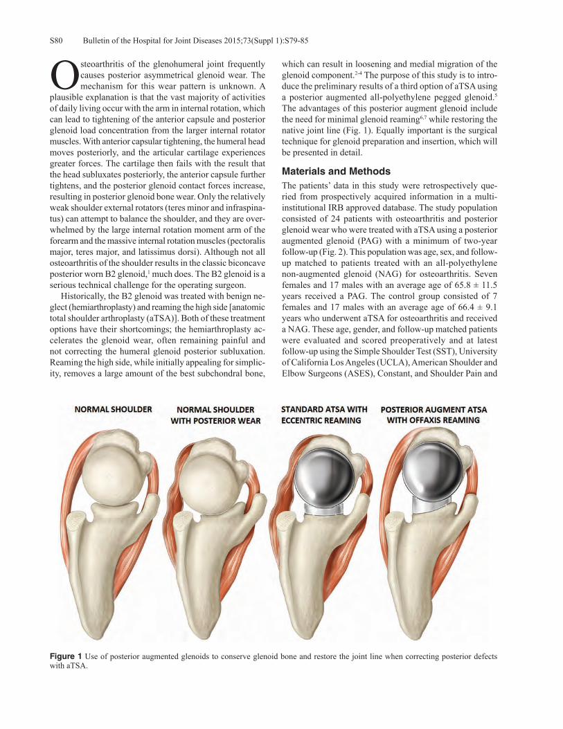
Bulletin of the Hospital for Joint Diseases 2015;73(Suppl 1):S79-85S80
Osteoarthritis of the glenohumeral joint frequently causes posterior asymmetrical glenoid wear. The mechanism for this wear pattern is unknown. A
plausible explanation is that the vast majority of activities of daily living occur with the arm in internal rotation, which can lead to tightening of the anterior capsule and posterior glenoid load concentration from the larger internal rotator muscles. With anterior capsular tightening, the humeral head moves posteriorly, and the articular cartilage experiences greater forces. The cartilage then fails with the result that the head subluxates posteriorly, the anterior capsule further tightens, and the posterior glenoid contact forces increase, resulting in posterior glenoid bone wear. Only the relatively weak shoulder external rotators (teres minor and infraspina-tus) can attempt to balance the shoulder, and they are over-whelmed by the large internal rotation moment arm of the forearm and the massive internal rotation muscles (pectoralis major, teres major, and latissimus dorsi). Although not all osteoarthritis of the shoulder results in the classic biconcave posterior worn B2 glenoid,1 much does. The B2 glenoid is a serious technical challenge for the operating surgeon. Historically, the B2 glenoid was treated with benign ne-glect (hemiarthroplasty) and reaming the high side [anatomic total shoulder arthroplasty (aTSA)]. Both of these treatment options have their shortcomings; the hemiarthroplasty ac-celerates the glenoid wear, often remaining painful and not correcting the humeral glenoid posterior subluxation. Reaming the high side, while initially appealing for simplic-ity, removes a large amount of the best subchondral bone,
which can result in loosening and medial migration of the glenoid component.2-4 The purpose of this study is to intro-duce the preliminary results of a third option of aTSA using a posterior augmented all-polyethylene pegged glenoid.5 The advantages of this posterior augment glenoid include the need for minimal glenoid reaming6,7 while restoring the native joint line (Fig. 1). Equally important is the surgical technique for glenoid preparation and insertion, which will be presented in detail.
Materials and MethodsThe patients’ data in this study were retrospectively que-ried from prospectively acquired information in a multi-institutional IRB approved database. The study population consisted of 24 patients with osteoarthritis and posterior glenoid wear who were treated with aTSA using a posterior augmented glenoid (PAG) with a minimum of two-year follow-up (Fig. 2). This population was age, sex, and follow-up matched to patients treated with an all-polyethylene non-augmented glenoid (NAG) for osteoarthritis. Seven females and 17 males with an average age of 65.8 ± 11.5 years received a PAG. The control group consisted of 7 females and 17 males with an average age of 66.4 ± 9.1 years who underwent aTSA for osteoarthritis and received a NAG. These age, gender, and follow-up matched patients were evaluated and scored preoperatively and at latest follow-up using the Simple Shoulder Test (SST), University of California Los Angeles (UCLA), American Shoulder and Elbow Surgeons (ASES), Constant, and Shoulder Pain and
Figure 1 Use of posterior augmented glenoids to conserve glenoid bone and restore the joint line when correcting posterior defects with aTSA.

S81Bulletin of the Hospital for Joint Diseases 2015;73(Suppl 1):S79-85
Disability Index (SPADI) scoring metrics; active abduction, elevation, and external rotation were also measured. Internal rotation was measured by vertebral segments and was scored by the following discrete assignment: trochanter = 1, but-tocks = 2, sacrum = 3, L5-L4 = 4, L3-L1 = 5, Th12-Th8 = 6, and Th7 or higher = 7. The average follow-up for aTSA patients with a PAG was 29.4 ± 7.9 months, and the aver-age follow-up for age and gender matched aTSA patients with a NAG was 29.6 ± 8.7 months. A Grashey and axillary lateral radiograph was evaluated at two-year follow-up. The Shoulder Arthroplasty Subluxation Index (SASI) was used to determine the degree of humeral component subluxation on the glenoid component (Fig. 3). The SASI uses the metallic
central post marker, which is extended as a straight line and intersects the humeral head arthroplasty. The humeral head is divided into thirds on both the axillary lateral and Grashey views. If the line contacts the humeral head in the central third, the subluxation is neutral. On the axillary lateral, if the line contacts the arthroplasty head in the posterior one-third, then the head is anteriorly subluxated; the reverse is the case if it contacts the head in the anterior segment. On the Grashey view, if the line contacts the humeral head arthroplasty in the inferior one-third, then the head is sub-luxated superiorly, and the opposite is also true. A Student’s two-tailed, unpaired t-test was used to identify differences in preoperative and postoperative results, where p < 0.05 denoted a significant difference.
ResultsAll patients demonstrated significant improvements in pain and function following treatment with the primary shoulder arthroplasty. The database contained zero complications for the aTSA patients with a PAG and zero complications for the NAG cohort. Radiographic data were available for 20 of 24 PAG patients and 15 of 24 NAG patients. Twelve of 20 PAG patients had a radiolucent line (60.0%) with an average radiographic line score of 1.10. Five of 15 NAG patients had a radiolucent line (33.3%) with an average ra-diographic line score of 0.438. One glenoid in the PAG group
Figure 2 Equinoxe® 8° posterior augment pegged glenoid (Ex-actech, Inc., Gainesville, FL); left and right devices depicted.
Figure 3 A, Schematic of a Grashey view of aTSA demonstrating Shoulder Arthroplasty Subluxation Index (SASI). B, Axillary schematic showing the SASI in that view.
B
A

Bulletin of the Hospital for Joint Diseases 2015;73(Suppl 1):S79-85S82
Figure 4 A, Preoperative Grashey view of patient with severe posterior glenoid wear and subluxation. B, Preoperative axillary lateral view of same patient with severe posterior glenoid wear and subluxation. C, MRI in the same patient demonstrating the same findings. D, Grashey view of the same patient one year postoperatively. E, Axillary lateral of the same patient 1 year postoperatively. Note, the humeral head is centered.
E
DC
BA
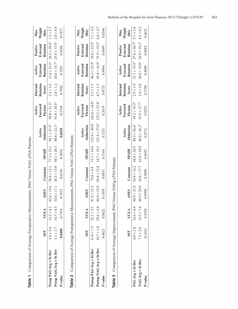
S83Bulletin of the Hospital for Joint Diseases 2015;73(Suppl 1):S79-85
Tab
le 1
C
ompa
rison
of A
vera
ge P
reop
erat
ive
Mea
sure
men
ts, P
AG
Ver
sus N
AG
aTS
A P
atie
nts
SST
UC
LA
ASE
SC
onst
ant
SPA
DI
Act
ive
Abd
uctio
n
Act
ive
Forw
ard
Flex
ion
Inte
rnal
R
otat
ion
Scor
e
Act
ive
Ext
erna
l R
otat
ion
Pass
ive
Ext
erna
l R
otat
ion
Max
W
eigh
t (lb
s)Pr
eop
PAG
Avg
± S
t Dev
5.0
± 2.
615
.2 ±
4.3
42.6
± 1
4.6
38.6
± 1
2.1
77.1
± 2
2.1
94.1
± 2
1.9°
99.0
± 2
1.2°
2.5
± 1.
613
.4 ±
21.
6°26
.3 ±
20.
4°1.
3 ±
2.7
Preo
p N
AG
Avg
± S
t Dev
3.1
± 2.
714
.7 ±
4.5
34.4
± 1
7.1
36.5
± 1
3.9
84.1
± 2
0.3
80.8
± 2
2.1°
91.0
± 2
8.8°
2.4
± 1.
220
.6 ±
15.
7°25
.8 ±
15.
8°2.
8 ±
4.4
P-va
lue
0.04
000.
7414
0.10
150.
6150
0.30
540.
0420
0.27
640.
7942
0.19
230.
9248
0.19
77
Tab
le 2
C
ompa
rison
of A
vera
ge P
osto
pera
tive
Mea
sure
men
ts, P
AG
Ver
sus N
AG
aTS
A P
atie
nts
SST
UC
LA
ASE
SC
onst
ant
SPA
DI
Act
ive
Abd
uctio
n
Act
ive
Forw
ard
Flex
ion
Inte
rnal
R
otat
ion
Scor
e
Act
ive
Ext
erna
l R
otat
ion
Pass
ive
Ext
erna
l R
otat
ion
Max
W
eigh
t (lb
s)Po
stop
PA
G A
vg ±
St D
ev11
.0 ±
1.5
32.1
± 3
.191
.5 ±
12.
575
.6 ±
9.4
13.1
± 1
8.6
133.
4 ±
20.4
°14
2.0
± 14
.0°
5.5
± 1.
546
.3 ±
23.
8°54
.8 ±
23.
6°7.
1 ±
4.2
Post
op N
AG
Avg
± S
t Dev
10.7
± 1
.829
.6 ±
4.8
84.9
± 1
5.0
69.4
± 1
2.4
18.7
± 1
8.5
121.
8 ±
27.0
°13
5.2
± 23
.8°
4.7
± 1.
345
.4 ±
16.
8°51
.9 ±
19.
2°6.
8 ±
4.7
P-va
lue
0.46
210.
0622
0.10
590.
0831
0.31
640.
1251
0.26
740.
0725
0.89
640.
6699
0.83
44
Tab
le 3
C
ompa
rison
of A
vera
ge Im
prov
emen
t, PA
G V
ersu
s NA
Gg
aTSA
Pat
ient
s
SST
UC
LA
ASE
SC
onst
ant
SPA
DI
Act
ive
Abd
uctio
n
Act
ive
Forw
ard
Flex
ion
Inte
rnal
R
otat
ion
Scor
e
Act
ive
Ext
erna
l R
otat
ion
Pass
ive
Ext
erna
l R
otat
ion
Max
W
eigh
t (lb
s)PA
G A
vg ±
St D
ev6.
0 ±
2.8
16.6
± 6
.448
.9 ±
21.
036
.9 ±
14.
264
.0 ±
28.
940
.3 ±
26.
6°43
.2 ±
19.
3°2.
9 ±
1.9
31.1
± 1
9.5°
27.0
± 2
0.7°
5.7
± 3.
8N
AG
Avg
± S
t Dev
7.3
± 2.
615
.2 ±
7.0
48.9
± 2
4.9
34.0
± 1
7.7
63.4
± 2
4.9
40.6
± 3
6.2°
43.9
± 3
7.7°
2.4
± 2.
026
.8 ±
19.
8°26
.9 ±
19.
2°4.
5 ±
6.2
P-va
lue
0.16
160.
5554
0.99
990.
5890
0.94
470.
9711
0.93
530.
3799
0.48
090.
9883
0.46
31

Bulletin of the Hospital for Joint Diseases 2015;73(Suppl 1):S79-85S84
is radiographically loose but not clinically loose. In the PAG group, the Grashey view showed that 18/20 humeral heads were centered with the two remaining joints demonstrating superior subluxation. On the axillary lateral in the PAG group, 17/20 humeral heads were centered, and three were anteriorly subluxated; none were posteriorly subluxated. A typical patient preoperatively and 1 year postoperatively is shown in Figure 4; note the larger posterior space consis-tent with the PAG. Also note that the humeral head is not posterior subluxated as it was preoperatively. The average preoperative, postoperative, and preoperative to postopera-tive improvement for each glenoid type is presented in Tables 1, 2, and 3, respectively. There were no differences in any of the measured postoperative clinical outcomes or any differ-ence in improvement between the two groups.
Surgical TechniqueComputerized tomography (CT) scan is used for preop-erative planning. The CT scan can estimate the degree of retroversion, the amount of humeral head subluxation, and the amount of posterior glenoid wear. In addition, it is useful to determine on the axillary cuts exactly where to place the starting hole for the central peg of the glenoid. Generally, the optimal central peg hole is at the B2 ridge or 1 mm behind it. Once the glenoid is exposed, the starting point for the reamer or guide pin is determined usually at the center or slightly above in the superior inferior axis and anterior on the anterior posterior axis. Because the surgeon cannot see the glenoid tangentially, the tendency is to place the starting point too posterior; in other words, the eyes will play tricks with this acute angle view (the glenoid is facing away for the surgeon). The thumb makes an excellent measuring stick. The starting point must not be placed posterior. At this point, the surgeon can use the K-wire guide technique or ream-it-flat technique. My recommendation is the ream-the-glenoid-flat technique as it is simple and relatively fast. With this technique, the center hole is drilled only deep enough to place the nub of the reamer in place; this will allow the surgeon to lever the reamer posterior. The goal is to ream away the ridge and get a circle with the reamer but not to correct the retroversion. With this technique, minimal glenoid bone is removed. Once the glenoid has been reamed to the appropriate sized reamer, the 8° or 16° posterior augmented guide is placed, and the center hole is fully drilled with the appropriate angled guide on the reamed surface. Next, the peripheral augmented guide of the same degree is used to drill the peripheral holes. The glenoid is trialed, and if stable, the actual implant is ce-mented in place using the triple pressurization technique.8 The humerus is then inserted in the standard fashion. Use of the shortest head is generally recommended. The joint will want to subluxate posterior, but this is easily corrected with the subscapularis repair and rotator cuff interval imbrication. The looser the joint, the more we close the
rotator cuff interval towards the coracoid. Resubluxation or dislocation posterior has not been a problem. If the surgeon opts for the K-wire guide technique, the K-wire is placed at the desired position for the central peg placement as described in the previous paragraph. The wire is advanced so as to come out just anterior and parallel to the glenoid neck, which the surgeon can palpate. The K-wire guide is then placed over this wire, and a second K-wire is placed through the 8° or 16° hole corresponding to the amount of correction desired. K-wire one is now removed, and a cannulated reamer is placed over K-wire two reaming the glenoid until flat. The K-wire guide is then replaced, and the K-wire one is reintroduced into its previous hole. K-wire two is now removed. A cannulated drill is then used to drill over K-wire one with subsequent removal of K-wire one. The 8° or 16° peripheral peg drill guide is then placed, and the peripheral holes are drilled. Glenoid preparation is now complete.
DiscussionThe problem of posterior glenoid wear is a significant one associated with inferior clinical results and a higher revision rate when compared to arthritis associated with concentric glenoids.1-3 Treatment of these complex patients has involved replacement of the humerus only or reaming the glenoid perpendicular (removing anterior glenoid bone) and then placing an aTSA. Both of these options have significant shortcomings, so much so that other options are now pro-posed, including the use of the augmented glenoid, bone grafting,9 reverse total shoulder arthroplasty (rTSA),10 and rTSA with bone grafting. Hemiarthroplasty leaves the joint subluxated and can increase glenoid wear as the metallic head is much harder than the native glenoid bone.11 Ream-ing of the high side removes much of the best glenoid bone, resulting in component loosening and medial migration. If the glenoid component is left in retroversion greater than 10°, the humeral head will posteriorly subluxate; the contact forces will rapidly increase, and the glenoid component will loosen.12
Rice and coworkers13 have the only reported series on posterior augmented glenoids. Their glenoid only corrected 5°, and the correction was all on the articular side, which left the pegs in a position to penetrate the anterior portion of the glenoid vault. Their results, however, were not par-ticularly severe, even though they abandoned the use of that implant. Our study used new implants very different than the Cofield implant as the correction is on the boney side, which allows the pegs to remain in the glenoid vault. It is provided in multiple sizes to correct defects either 8° or 16° of retroversion (Fig. 2). Radiographically, the rate of lucent lines was slightly higher than the control group without glenoid wear. No implant has been revised to date, though one is radiographi-cally but not clinically loose. No humeral heads resublux-ated posteriorly. Finally, clinically, there was no difference

S85Bulletin of the Hospital for Joint Diseases 2015;73(Suppl 1):S79-85
between the PAG and NAG groups at two-year follow-up.
ConclusionIt is our opinion that in patients with up to 25° of glenoid retroversion who are relatively active, with reaming away the glenoid B2 ridge and placing the 16° augment, the joint line will be restored to within 5° of neutral. In more severe deformities consideration should be given to treatment with a rTSA using an augment or bone graft. In very low-demand patients, a rTSA may also be the best solution. Based on this short-term follow-up, a PAG is a viable option for active patients with a good rotator cuff and glenoid deformities of 25° of retroversion or less.
Disclosure Statement Thomas W. Wright, M.D., Sean G. Grey, M.D., Pierre-Henri Flurin, M.D., and Joseph D. Zuckerman, M.D., are consul-tants for Exactech, Inc., and receive royalties on products related to this article. Logan Wright, has no disclosures to report. Christopher P. Roche, M.S., M.B.A., is an employee of Exactech, Inc., Gainesville, Florida.
References1. Walch G, Boulahia A, Boileau P, Kempf JF. Primary glenohu-
meral osteoarthritis: clinical and radiographic classification. The Aequalis Group. Acta Orthop Belg. 1998;64 Suppl 2:46-52.
2. Dillon MT, Ake CF, Burke MF, et al. The Kaiser Perma-nente shoulder arthroplasty registry. Acta Orthop. 2015 Jun;86(3):286-92.
3. Hussey MM, Steen BM, Cusick MC, et al. The effects of glenoid wear patterns on patients with osteoarthritis in total shoulder arthroplasty: an assessment of outcomes and value.
J Shoulder Elbow Surg. 2015 May;24(5):682-90. 4. Walch G, Moraga C, Young A, et al. Results of anatomic non-
constrained prosthesis in primary osteoarthritis with biconcave glenoid. J Shoulder Elbow Surg. 2012 Nov;21(11):1526-33.
5. Hsu JE, Ricchetti ET, Huffman GR, et al. Addressing glenoid bone deficiency and asymmetric posterior erosion in shoulder arthroplasty. J Shoulder Elbow Surg. 2013 Sep;22(9):1298-308.
6. Kersten AD, Flores-Hernandez C, Hoenecke HR, D’Lima DD. Posterior augmented glenoid designs preserve more bone in biconcave glenoids. J Shoulder Elbow Surg. 2015 Jul;24(7):1135-41.
7. Roche CP, Diep P, Grey SG, Flurin PH. Biomechanical impact of posterior glenoid wear on anatomic total shoulder arthro-plasty. Bull Hosp Jt Dis(2013). 2013;71(Suppl 2):S5-11.
8. Choi T, Sahajpal D, Horodyski MB, et al. Incidence of early radiolucent lines after glenoid component insertion for total shoulder arthroplasty: a radiographic study comparing pres-surized and unpressurized cementing techniques. J Shoulder Elbow Surg. 2013 Mar;22(3):403-8.
9. Scalise JJ, Iannotti JP. Bone grafting severe glenoid defects in revision shoulder arthroplasty. Clin Orthop Relat Res. 2008 Jan;466(1):139-45.
10. Gallusser N, Farron A. Complications of shoulder arthroplasty for osteoarthritis with posterior glenoid wear. Orthop Trau-matol Surg Res. 2014 Sep;100(5):503-8.
11. Levine WN, Fischer CR, Nguyen D, et al. Long-term follow-up of shoulder hemiarthroplasty for glenohumeral osteoarthri-tis. J Bone Joint Surg Am. 2012 Nov 21;94(22):e164.
12. Shapiro TA, McGarry MH, Gupta R, et al. Biomechanical effects of glenoid retroversion in total shoulder arthroplasty. J Shoulder Elbow Surg. 2007 May-Jun;16(3 Suppl):S90-5.
13. Rice RS, Sperling JW, Miletti J, et al. Augmented glenoid component for bone deficiency in shoulder arthroplasty. Clin Orthop Relat Res. 2008 Mar;466(3):579-83.

Bulletin of the Hospital for Joint Diseases 2015;73(Suppl 1):S86-91S86
Grey SG, Wright TW, Flurin P-H, Zuckerman JD, Freidman R, Roche CP. Preliminary results of a novel hybrid cage glenoid compared to an all-polyethylene glenoid in total shoulder arthroplasty. Bull Hosp Jt Dis. 2015;73(Suppl 1):S86-91.
Abstract
Introduction: The aim of this study was to evaluate the preliminary outcomes of a hybrid cage glenoid design in comparison to pegged all-polyethylene glenoid components in anatomic total shoulder arthroplasty (aTSA). Materials and Methods: Ninety-two patients undergoing primary anatomic total shoulder arthroplasty with minimum two-year follow-up were reviewed. Forty-six patients had an ultra-high molecular weight polyethylene (UHMWPE) cemented pegged glenoid component, and 46 had a hybrid cage glenoid component. Patient data was retrospectively reviewed from prospectively acquired data in a multi-institutional IRB approved database. These age, gender, and follow-up matched patients were evaluated and scored preoperatively and a latest follow-up using the SST, UCLA, ASES, Constant, and SPADI scoring metrics. Additional measures included active abduction, elevation, and external rotation. Radiolucent line assessment of the glenoid was performed by use of a Grashey and axillary radiograph at latest follow-up. A Student’s two tailed, unpaired t-test was used to identify differences in preoperative and postoperative results, where p < 0.05 denoted a significant difference. Results: All patients demonstrated significant improve-ments in pain and function following treatment with the
primary aTSA. The database contained three complications for the aTSA patients with a cage glenoid, and three com-plications for patients with a UHMWPE pegged glenoid. Radiographic data was available for 37 of 46 cage glenoid patients and 29 of 46 UHMWPE pegged glenoid patients. Five of 37 cage glenoid patients had a radiolucent line (13.5%) with an average radiographic line score of 0.22. Eight of 29 UHMWPE peg glenoid patients had a radiolu-cent line (27.6%) with an average radiographic line score of 0.57. Cage aTSA patients were associated with signifi-cantly less blood loss than aTSA UHMWPE pegged glenoid patients (avg. blood loss = 242 vs. 337; p = 0.022). Conclusion: At minimum two-year follow-up, hybrid cage aTSA components show equal clinical outcomes to UHMWPE pegged glenoids. However, the hybrid cage components had significantly fewer radiolucent lines and less intra-operative blood loss. Additional and longer-term clinical and radiographic follow-up is necessary to confirm these promising early results.
While the overall success rate for anatomic total shoulder arthroplasty (aTSA) is good, glenoid-sided aseptic loosening remains the most com-
mon long-term complication.1 Radiographic evidence of lucent lines has been reported to range from 22% to 95% in various types of glenoid implants.2-8 Although a variety of glenoid designs exist in the USA at this time, all-polyethylene cemented peg glenoid designs remain the gold standard.4-9 In these pegged all-polyethylene glenoid components, radiolucent lines are common and aseptic gle-noid loosening remains the primary concern for longevity of the device. This incidence of lucent lines and glenoid component loosening led to interest in a variety of metal-backed and bone in-growth devices.4,10-13 Uncemented or limitedly ce-mented implants offer the potential to reduce the historical
Preliminary Results of a Novel Hybrid Cage Glenoid Compared to an All-Polyethylene Glenoid in Total Shoulder Arthroplasty
Sean G. Grey, M.D., Thomas W. Wright, M.D., Pierre-Henri Flurin, M.D., Joseph D. Zuckerman, M.D., Richard Friedman, M.D., F.R.C.S.C., and Christopher P. Roche, M.S., M.B.A.
Sean G. Grey, M.D., Orthopaedic Center of the Rockies, Fort Col-lins, Colorado. Thomas W. Wright, M.D., Department of Orthopae-dics and Rehabilitation, University of Florida, Gainesville, Florida. Pierre-Henri Flurin, M.D., Bordeaux-Merignac Clinique du Sport, Merignac, France. Joseph D. Zuckerman, M.D., Department of Orthopaedic Surgery, Hospital for Joint Diseases, NYU Langone Medical Center, New York, New York. Richard Friedman, M.D., F.R.C.S.C., Medical University of South Carolina, Charleston, South Carolina. Christopher P. Roche, M.S., M.B.A., Exactech, Inc., Gainesville, Florida. Correspondence: Sean G. Grey, M.D., [email protected].

S87Bulletin of the Hospital for Joint Diseases 2015;73(Suppl 1):S86-91
aseptic glenoid loosening rate at longer term follow-up. A number of metal-backed uncemented designs have been con-ceived and are currently available in the USA and Europe. When compared to cemented all-polyethylene glenoids, previous metal-backed designs have shown higher failure rates for a variety of reasons.4,10-13 Inclusion of metal backing results in relatively thin polyethylene and/or overstuffing of the joint. This decreased polyethylene thicknesses in combination with increased polyethylene contact pressures result in polyethylene fracture or accelerated wear rates, osteolysis, and ultimately loosening.10 A number of metal-backed designs had no bone in-growth surface/coating; initial fixation was obtained with the use of screws. Lack of an in-growth surface led to eventual loosening of the screws under repetitive loads.1 Trabecular metal and other highly porous materials/designs, in which there is no metal backing on the face of the glenoid, have shown excellent bone in-growth but have had problems with metal fracture and dissociation at the trabecular metal/polyethylene im-plant interface.9 This has been accompanied by higher early revisions for aseptic loosening. Lack of peripheral pegs to control rotational forces between the trabecular metal and polyethylene may be a contributing factor.9
Limited cementing with all-polyethylene designs have shown some promise.14-16 In this hybrid design, early fixation is obtained with a combination of peripheral peg cementation and interference fit of the central peg. Long-term fixation is supplemented with documented bone in-growth around the phalanges of the all-polyethylene central peg.16 Some studies, however, have also shown radiolucency around the central peg, and there is concern that the flanges may not represent the best long-term surface for bone fixation.17 The purpose of this paper is to study the 2-year minimum clinical outcome data of a new glenoid design which incorporates a bone through-growth commercially pure titanium plasma coated central cage connected to a 4 mm thick fully-molded all-polyethylene four pegged glenoid (Fig. 1). Early clinical
and radigraphic results are presented, as well as the surgical technique.
Materials and MethodsAfter IRB approval, patient data from a prospectively acquired multi-institutional database was retrospectively reviewed. Participants in this study consist of 92 (average age: 63.2 ± 9.4 years) patients with an aTSA performed for osteoarthritis. All patients had greater than 2-year follow-up (average follow-up = 25.5 ± 4.8 months) and utilized the same humeral stem (Equinoxe® platform shoulder; Exactech, Inc.). Forty-six patients, 19 females (average age: 65.6 years) and 27 males (average age: 61.4 years) had primary aTSA with the cage glenoid implant. Forty-six age, sex, and follow-up matched patients, 19 female (average age: 64.7 years) and 27 males (average age: 62.2 years), had aTSA with cemented UHMWPE pegged component. These age, sex, diagnosis, and follow-up patients were evaluated and scored preoperatively and at latest postoperative follow-up using SST, UCLA, ASES, Constant, and SPADI scoring metrics. Active range of motion, including forward flexion, abduction, external rotation and internal rotation, was also measured. Internal rotation was also measured by vertebral segment with the following discrete assignment: 0° = 0, hip = 1, buttocks = 2, sacrum = 3, L5-L4 = 4, L3-L1 = 5, T12-T8 = 6, and T7 or higher = 7. Average follow-up for aTSA with cage glenoid was 25.3 ± 4.8 months. Average follow-up for aTSA with UHMWPE pegged implant was 25.6 months ± 4.8 months. True anterior-posterior (AP) and axillary lateral radiographs were obtained postoperatively and at scheduled follow-ups, including the 2-year postoperative evaluation. These radiographs were evaluated and graded for the pres-ence of radiolucent lines by the operating surgeon at the bone cement interface according to the method of Lazarus and coworkers (Table 1 and Fig. 2).18 Statistical analysis was performed using a Student’s two-tailed, unpaired t-test to identify differences in preoperative and postoperative results,
Figure 1 Equinoxe® cage glenoid (Exactech, Inc., Gainesville, FL).
Table 1 Pegged Glenoid Radiographic Line Scoring System*
Radiolucent Line Grade Pegged Glenoid0 No Radiolucency1 Incomplete Radiolucency Around 1 or 2 Pegs2 Complete Radiolucency Around 1 Peg only
(< 2 mm); Irrespective of Incomplete Radiolucency Around 1 other Peg
3 Complete Radiolucency Around 2 or more Pegs (< 2 mm)
4 Complete Radiolucency Around 2 or more Pegs (> 2 mm)
5 Gross Loosening
*Adapted from Lazarus MD, Jensen KL, Southworth C, Matsen FA 3rd. The radiographic evaluation of keeled and pegged glenoid component insertion. J Bone Joint Surg Am. 2002 Jul;84A(7):1174-82.
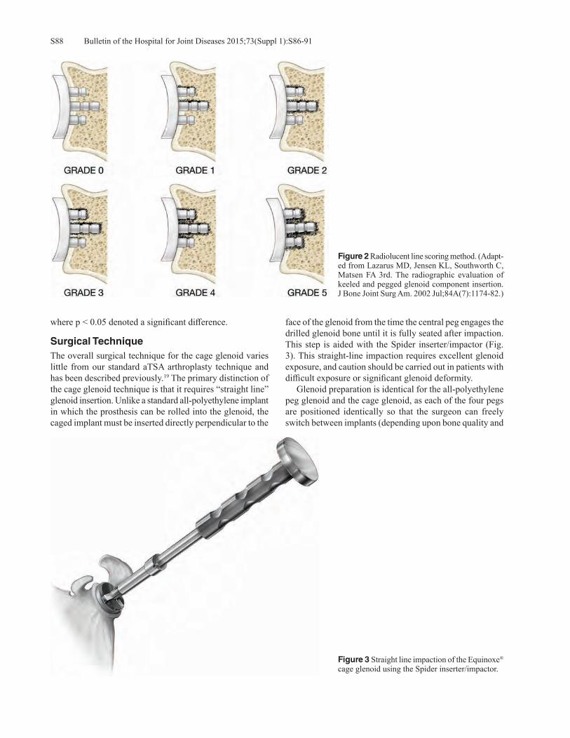
Bulletin of the Hospital for Joint Diseases 2015;73(Suppl 1):S86-91S88
where p < 0.05 denoted a significant difference.
Surgical Technique The overall surgical technique for the cage glenoid varies little from our standard aTSA arthroplasty technique and has been described previously.19 The primary distinction of the cage glenoid technique is that it requires “straight line” glenoid insertion. Unlike a standard all-polyethylene implant in which the prosthesis can be rolled into the glenoid, the caged implant must be inserted directly perpendicular to the
face of the glenoid from the time the central peg engages the drilled glenoid bone until it is fully seated after impaction.This step is aided with the Spider inserter/impactor (Fig. 3). This straight-line impaction requires excellent glenoid exposure, and caution should be carried out in patients with difficult exposure or significant glenoid deformity. Glenoid preparation is identical for the all-polyethylene peg glenoid and the cage glenoid, as each of the four pegs are positioned identically so that the surgeon can freely switch between implants (depending upon bone quality and
Figure 2 Radiolucent line scoring method. (Adapt-ed from Lazarus MD, Jensen KL, Southworth C, Matsen FA 3rd. The radiographic evaluation of keeled and pegged glenoid component insertion. J Bone Joint Surg Am. 2002 Jul;84A(7):1174-82.)
Figure 3 Straight line impaction of the Equinoxe® cage glenoid using the Spider inserter/impactor.
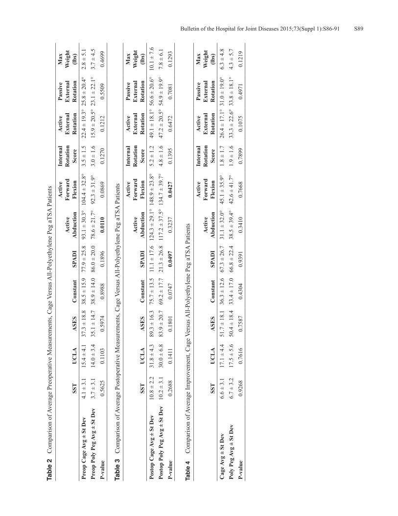
S89Bulletin of the Hospital for Joint Diseases 2015;73(Suppl 1):S86-91
Tab
le 2
C
ompa
rison
of A
vera
ge P
reop
erat
ive
Mea
sure
men
ts, C
age
Vers
us A
ll-Po
lyet
hyle
ne P
eg a
TSA
Pat
ient
s
SST
UC
LA
ASE
SC
onst
ant
SPA
DI
Act
ive
Abd
uctio
n
Act
ive
Forw
ard
Flex
ion
Inte
rnal
R
otat
ion
Scor
e
Act
ive
Ext
erna
l R
otat
ion
Pass
ive
Ext
erna
l R
otat
ion
Max
W
eigh
t (lb
s)Pr
eop
Cag
e Avg
± S
t Dev
4.1
± 3.
115
.4 ±
4.1
37.3
± 1
8.8
38.5
± 1
5.9
77.9
± 2
5.8
93.1
± 3
0.3°
104.
4 ±
32.8
°3.
5 ±
1.5
22.4
± 1
9.3°
25.8
± 2
0.4°
2.8
± 5.
1Pr
eop
Poly
Peg
Avg
± S
t Dev
3.7
± 3.
114
.0 ±
3.4
35.1
± 1
4.7
38.9
± 1
4.0
86.0
± 2
0.0
78.6
± 2
1.7°
92.3
± 3
1.9°
3.0
± 1.
615
.9 ±
20.
5°23
.1 ±
22.
1°3.
7 ±
4.5
P-va
lue
0.56
250.
1103
0.59
740.
8988
0.18
960.
0110
0.08
690.
1270
0.12
120.
5509
0.46
99
Tab
le 3
C
ompa
rison
of A
vera
ge P
osto
pera
tive
Mea
sure
men
ts, C
age
Vers
us A
ll-Po
lyet
hyle
ne P
eg a
TSA
Pat
ient
s
SST
UC
LA
ASE
SC
onst
ant
SPA
DI
Act
ive
Abd
uctio
n
Act
ive
Forw
ard
Flex
ion
Inte
rnal
R
otat
ion
Scor
e
Act
ive
Ext
erna
l R
otat
ion
Pass
ive
Ext
erna
l R
otat
ion
Max
W
eigh
t (lb
s)Po
stop
Cag
e Avg
± S
t Dev
10.8
± 2
.231
.8 ±
4.3
89.3
± 1
6.3
75.7
± 1
3.5
11.1
± 1
7.6
124.
3 ±
29.1
°14
8.9
± 23
.8°
5.2
± 1.
249
.1 ±
18.
1°56
.6 ±
20.
6°10
.1 ±
7.6
Post
op P
oly
Peg
Avg
± St
Dev
10.2
± 3
.130
.0 ±
6.8
83.9
± 2
0.7
69.2
± 1
7.7
21.3
± 2
6.8
117.
2 ±
37.5
°13
4.7
± 39
.7°
4.8
± 1.
647
.2 ±
20.
5°54
.9 ±
19.
9°7.
8 ±
6.1
P-va
lue
0.26
880.
1411
0.18
010.
0747
0.04
970.
3237
0.04
270.
1395
0.64
720.
7081
0.12
93
Tab
le 4
C
ompa
rison
of A
vera
ge Im
prov
emen
t, C
age
Vers
us A
ll-Po
lyet
hyle
ne P
eg a
TSA
Pat
ient
s
SST
UC
LA
ASE
SC
onst
ant
SPA
DI
Act
ive
Abd
uctio
n
Act
ive
Forw
ard
Flex
ion
Inte
rnal
R
otat
ion
Scor
e
Act
ive
Ext
erna
l R
otat
ion
Pass
ive
Ext
erna
l R
otat
ion
Max
W
eigh
t (lb
s)C
age A
vg ±
St D
ev6.
6 ±
3.1
17.1
± 4
.451
.7 ±
18.
136
.3 ±
12.
667
.3 ±
26.
731
.1 ±
32.
0°45
.1 ±
35.
9°1.
8 ±
1.7
26.4
± 1
7.1°
31.0
± 1
9.0°
6.3
± 4.
8Po
ly P
eg A
vg ±
St D
ev6.
7 ±
3.2
17.5
± 5
.650
.4 ±
18.
433
.4 ±
17.
066
.8 ±
22.
438
.5 ±
39.
4°42
.6 ±
41.
7°1.
9 ±
1.6
33.3
± 2
2.6°
33.8
± 1
8.1°
4.3
± 5.
7P-
valu
e0.
9268
0.76
160.
7587
0.43
040.
9391
0.34
100.
7668
0.78
990.
1075
0.49
710.
1219

Bulletin of the Hospital for Joint Diseases 2015;73(Suppl 1):S86-91S90
exposure) after the surface has been reamed and the peg holes have been drilled. Two orthogonal lines are drawn, dividing the anterior-posterior and superior-inferior halves of the glenoid face. The proper position of the central peg hole is consistently just anterior and superior to the intersec-tion of these two lines. The position is confirmed with the glenoid drill guide. The central hole can be drilled either through the guide or in a freehand method. Sequential ream-ing is carried out to the appropriate size. After trialing, the option of either an all-polyethylene glenoid or cage glenoid component still exists. If straight-line insertion is possible and bone density is adequate, a cage glenoid component is selected; however, if straight-line insertion is not possible, either further releases are performed, or the all-polyethylene pegged glenoid is selected. The glenoid is prepared in the standard fashion for ce-mentation. The peripheral holes are irrigated free of blood and debris, and cement is pressurized into only the periph-eral holes. Straight-line insertion is paramount, as off-axis and eccentric impaction may lead to damage to the locking mechanism that fixes the pegs to the glenoid component. After impaction, care should be taken to assess full seating of the entire glenoid, particularly posterior.
ResultsAll patients demonstrated a significant improvement in pain and function following treatment with primary aTSA using either glenoid component. A few differences were noted be-tween the cohorts. Table 2 shows that mean active abduction was greater preoperatively for the cage glenoid cohort. Table 3 shows that the mean SPADI score was superior, and the mean active forward flexion measurement was greater for the cage glenoid cohort postoperatively as compared to the all-polyethylene peg glenoid cohort. However, as presented in Table 4, there were no statistically significant differences in the improvement of range of motion or outcome scores for either group. The database contained three complications for the cage glenoid cohort (one infection, one adhesive capsulitis, and one aseptic humeral loosening) and three complications for the all-polyethylene peg glenoid cohort (two infections and one aseptic glenoid loosening). Radiographic data was available for 37 of 46 (80.0%) cage glenoid patients and 29 of 46 (63.0%) UHMWPE pegged patients. Five of 37 cage glenoid patients had a radiolucent line (13.5%) with an average radiographic line score of 0.22. Eight of 29 UHMWPE pegged glenoids had a radiolucent line (27.6%) with an average radiographic line score average of 0.57. Additionally, average surgical blood loss in patients receiving a cage glenoid aTSA was signifi-cantly less than that for patients receiving an UHMWPE peg glenoid aTSA (242 ± 130 ml vs. 337 ± 207 ml, p = 0.022).
DiscussionCemented pegged all-polyethylene glenoid components have been recognized as the current gold standard for
aTSA. While clinical results are good with cemented all-polyethylene glenoid components, aseptic loosening remains an unsolved problem and a major cause of long-term failure in aTSA. Previous attempts at uncemented and limited cemented glenoid implants have met with very limited suc-cess.1,4,11 The primary disadvantage of these implants has been the need for metal backing. The results of this comparison study demonstrate that the novel hybrid cage glenoid has equivalent short-term clinical outcome results and equivalent complication rates as the gold-standard all-polyethylene peg glenoid at 2-year minimum follow-up. Over 5,000 of these devices have been implanted worldwide since 2011, with a very minimal number of reported complaints. Additionally, the cage gle-noid implant showed less than half the rate of radiolucent lines (13.5% vs. 27.6%) and less than half the average radiographic line score (0.22 vs. 0.57) than the cemented all-polyethylene peg glenoid implant. Finally, significantly lower blood loss (242 ± 130 vs. 337 ± 207 ml blood loss, p = 0.022) was noted in the cage glenoid cohort. This lower blood loss was felt to be related to decreased operative time, owing to the immediate interference fit of the cage peg and not having to wait for cement curing. This clinical outcome comparison study has some limita-tions. It presents the short-term clinical results of two differ-ent glenoid designs using a database. While incorporating data from multiple sites improves the generalizability of the experience, it also introduces differences in technique and method between sites. Furthermore, there is inherent bias in the operating surgeon scoring their own radiographic results. The rate of radiographic follow-up also needs to improve; while complete radiographs were obtained for 80% of cage glenoid patients, only 63% of all-polyethylene peg glenoid patients had complete radiographic follow-up. Future work should utilize a single or multiple independent evaluators to perform a more complete radiographic analysis between co-horts. Finally, longer-term clinical and radiographic follow-up are needed to determine if these theoretical advantages will result in lower rates of aseptic glenoid loosening and better implant survivorship.
ConclusionAt two-year minimum follow-up, hybrid cage glenoids show equivalent short-term clinical outcomes as all-polyethylene pegged glenoid implants. Furthermore, the cage glenoid implant was demonstrated to have significantly fewer radiolucent lines, and the procedure is associated with sig-nificantly lower intraoperative blood loss compared with aTSA with the all-polyethylene peg glenoid. Longer-term clinical follow-up and more intense radiographic scrutiny are required to confirm these results. However, these short-term results are promising and suggest that the hybrid cage gle-noid may provide an alternative to gold-standard cemented all-polyethylene peg glenoids, having a potential for a lower risk of aseptic glenoid loosening.

S91Bulletin of the Hospital for Joint Diseases 2015;73(Suppl 1):S86-91
Disclosure Statement Sean G. Grey, M.D., Thomas W. Wright, M.D., Pierre-Henri Flurin, M.D., and Joseph D. Zuckerman, M.D., are consul-tants for Exactech, Inc., and receive royalties on products related to this article. Richard Friedman, M.D., F.R.C.S.C., is a consultant for Exactech, Inc. Christopher P. Roche, M.S., M.B.A., is employed by Exactech, Inc., Gainesville, Florida.
References1. Castagna A, Randelli M, Garofalo R, et al. Mid-term results of
a metal-backed glenoid component in total shoulder replace-ment. J Bone Joint Surg Br. 2010 Oct;92(10):1410-5.
2. Throckmorton TW, Zarkadas PC, Sperling JW, Cofield RH. Pegged versus keeled glenoid components in total shoulder arthroplasty. J Shoulder Elbow Surg. 2010 Jul;19(5):726-33.
3. Bohsali KI, Wirth MA, Rockwood CA Jr. Complications of total shoulder arthroplasty. J Bone Joint Surg Am. 2006 Oct;88(10):2279-92.
4. Boileau P, Avidor C, Krishnan SG, et al. Cemented polyeth-ylene versus uncemented metal-backed glenoid components in total shoulder arthroplasty: a prospective, double-blind, randomized study. J Shoulder Elbow Surg. 2002 Jul-Aug;11(4):351-9.
5. Boyd AD Jr, Thomas WH, Scott RD, et al. Total shoulder arthroplasty versus hemiarthroplasty. Indications for glenoid resurfacing. J Arthroplasty. 1990 Dec;5(4):329-36.
6. Brenner BC, Ferlic DC, Clayton ML, Dennis DA. Survivor-ship of unconstrained total shoulder arthroplasty. J Bone Joint Surg Am. 1989 Oct;71(9):1289-96.
7. Cofield RH. Total shoulder arthroplasty with the Neer pros-thesis. J Bone Joint Surg Am. 1984 Jul;66(6):899-906.
8. Norris BL, Lachiewicz PF. Modern cement technique and the survivorship of total shoulder arthroplasty. Clin Orthop Relat Res. 1996 Jul;(328):76-85.
9. Budge MD, Kurdziel MD, Baker KC, Wiater JM. A bio-mechanical analysis of initial fixation options for porous-tantalum-backed glenoid components. J Shoulder Elbow Surg.
2013 May;22(5):709-15. 10. Fox TJ, Cil A, Sperling JW, et al. Survival of the glenoid
component in shoulder arthroplasty. J Shoulder Elbow Surg. 2009 Nov-Dec;18(6):859-63.
11. Fucentese SF, Costouros JG, Kühnel SP, Gerber C. Total shoulder arthroplasty with an uncemented soft-metal-backed glenoid component. J Shoulder Elbow Surg. 2010 Jun;19(4):624-31.
12. Tammachote N, Sperling JW, Vathana T, et al. Long-term results of cemented metal-backed glenoid components for osteoarthritis of the shoulder. J Bone Joint Surg Am. 2009 Jan;91(1):160-6.
13. Wallace AL, Phillips RL, MacDougal GA, et al. Resurfacing of the glenoid in total shoulder arthroplasty. A comparison, at a mean of five years, of prostheses inserted with and without cement. J Bone Joint Surg Am. 1999 Apr;81(4):510-8.
14. Groh GI. Survival and radiographic analysis of a glenoid component with a cementless fluted central peg. J Shoulder Elbow Surg. 2010 Dec;19(8):1265-8.
15. Churchill RS, Zellmer C, Zimmers HJ, Ruggero R. Clinical and radiographic analysis of a partially cemented glenoid implant: five-year minimum follow-up. J Shoulder Elbow Surg. 2010 Oct;19(7):1091-7.
16. De Wilde L, Dayerizadeh N, De Neve F, et al. Fully unce-mented glenoid component in total shoulder arthroplasty. J Shoulder Elbow Surg. 2013 Oct;22(10):e1-7.
17. Vidil A, Valenti P, Guichoux F, Barthas JH. CT scan evalu-ation of glenoid component fixation: a prospective study of 27 minimally cemented shoulder arthroplasties. Eur J Orthop Surg Traumatol. 2013 Jul;23(5):521-5.
18. Lazarus MD, Jensen KL, Southworth C, Matsen FA 3rd. The radiographic evaluation of keeled and pegged glenoid component insertion. J Bone Joint Surg Am. 2002 Jul;84-A(7):1174-82.
19. Grey SG. Use of a caged, bone ingrowth, glenoid implant in anatomic total shoulder arthroplasty technique and early results. Bull Hosp Jt Dis (2013). 2013;71(Suppl 2):S41-5.

Bulletin of the Hospital for Joint Diseases 2015;73(Suppl 1):S92-8S92
Flurin P-H, Roche CP, Wright TW, Zuckerman JD. Correlation between clinical outcomes and anatomic reconstruction with anatomic total shoulder arthroplasty. Bull Hosp Jt Dis. 2015;73(Suppl 1):S92-8.
Abstract
Many glenohumeral studies have demonstrated how anatomy varies across the population. Third and fourth generation shoulder prosthesis designs were developed to provide greater modularity and size ranges to better reproduce this anatomy and thus achieve better results in terms of shoulder function. This study quantifies the quality of anatomic reconstruction and compares that to long-term clinical outcomes using one fourth generation platform shoulder system. Methodology: One hundred and forty primary total shoulder arthroplasties were performed by one experienced single surgeon between 2001 and 2009, using the same fourth generation modular prosthesis. Pre- and postopera-tive clinical assessments were quantified with the Constant, ASES, SPADI, SST, and UCLA scores, and active range of motion was measured. Five anatomic parameters were defined, measured, and compared pre- and postoperatively on the anterior-posterior (AP) radiographs: Humeral Head Height (HHH), Humeral Head Centering (HHC), Humeral Head Medial Offset (HHMO), Humeral Head Diameter (HHD), and Humeral Neck Angle (HNA). The differences between each of the parameters were then calculated and rated from 0 to 2 and then summed for each patient to obtain the Anatomic Reconstruction Index (ARI), which objectively quantifies and assesses the quality of the anatomic recon-struction. Patients were sorted based upon their ARI score
into two groups (ARI 5 to 7 and ARI 8 to 10), and their latest follow-up outcomes were compared using the Mann-Whitney test to identify differences in preoperative and postoperative results, where p < 0.05 denoted a significant difference. Results: Of the 140 primary prostheses performed, 78 patients were lost to follow-up, and 13 were excluded for complications that were not related to the anatomic recon-struction. Forty-nine patients (75.8 yrs., 31F/18M) were included with an average follow-up of 9.1 years. The aver-age score for HHH was 1.9 ± 0.4, 1.8 ± 0.5 for HHC, 1.7 ± 0.5 for HHMO, 1.7 ± 0.5 for HHD, and 1.5 ± 0.7 for HNA. Thus, all reconstructions were rated good to excellent with 86% of very good/excellent reconstruction (ARI 8 to 10) and 14% good reconstruction (ARI 5 to 7). A comparison of radiographic anatomic parameters was performed for these two cohorts: HHC (< 0.0001), HNA (0.000), and ARI (<0.0001) were significantly greater for the ARI 8 to 10 cohort. Four of five postoperative clinical outcome metrics for the ARI 8 to 10 cohort were significantly greater than the mean values for the ARI 5 to 7 cohort. Additionally, mean postoperative pain on a daily basis and shoulder function for the ARI 8 to 10 cohort were significantly greater than that for the ARI 5 to 7 cohort. Discussion: The relatively small number of good recon-structions (14%) compared to very good/excellent recon-structions (86%) and the absence of fair/poor reconstruc-tions limited the ability for any strong linear correlations between anatomical reconstruction and clinical parameters. Despite this, patients with larger mean ARI scores were associated with significantly better outcomes for some measures. This study is limited by the use of 2D assessments from standard AP radiographs; this method can be further refined by the use of 3D quantitative assessment of each parameter. Conclusion: This study confirmed that an improved ana-tomic reconstruction results in better postoperative clinical
Correlation Between Clinical Outcomes and Anatomic Reconstruction with Anatomic Total Shoulder Arthroplasty
Pierre-Henri Flurin, M.D., Christopher P. Roche, M.S., M.B.A., Thomas W. Wright, M.D., and Joseph D. Zuckerman, M.D.
Pierre-Henri Flurin, M.D., Bordeaux-Merignac Clinique du Sport, Merignac, France. Christopher P. Roche, M.S., M.B.A., Exactech, Inc., Gainesville, Florida. Thomas W. Wright, M.D., Depart-ment of Orthopaedics and Rehabilitation, University of Florida, Gainesville, Florida. Joseph D. Zuckerman, M.D., Department of Orthopaedic Surgery, Hospital for Joint Diseases, NYU Langone Medical Center, New York, New York.Correspondence: Pierre-Henri Flurin, M.D., [email protected].

S93Bulletin of the Hospital for Joint Diseases 2015;73(Suppl 1):S92-8
outcomes. The fourth generation prosthesis used for this study allows continuous in-situ adjustment of the humeral head orientation through use of the spherical taper on the replicator plate and also a double adjustment of offset through the use of the offset humeral head and offset taper on the replicator plate.
Charles Neer determined that a shoulder prosthesis that would reproduce, as closely as possible, the natural anatomy should provide the best clinical
outcomes. Despite the results published in 1955 showing a significant improvement in shoulder function, the first-generation prostheses failed to fully achieve this objective, mainly because of the limited size of implants available and their inability to account for the range and variability of proximal humeral anatomy.1,2
From the 1970s, the second generation of shoulder prostheses developed around the concept of modularity, which moved closer to the vision of Neer to create a more anatomical reconstruction. Their results were marked by difficulties resulting from two main factors: malposition of the center of rotation and oversizing the humeral head; both of which negatively influenced rotator cuff function and glenoid fixation, a limiting factor in the life of total shoulder arthroplasty.3,4
Many studies have analyzed the morphology of the shoulder and demonstrated how its anatomy varies across the population. In light of this information, third and fourth generation shoulder prosthesis designs were developed to provide greater modularity and size ranges to better repro-duce the anatomy with even more precision and thus achieve
better results in terms of shoulder function and longevity of prosthetic implants.3,5-13
Our first anatomic correlation study conducted in 2004 on a series of 50 fourth generation Equinoxe® prostheses with a mean follow-up of 23.8 months compared the quality of anatomic reconstruction on short-term clinical outcomes. Analysis of preoperative and postoperative x-rays were used to develop an anatomical reconstruction index and revealed strong correlations between the quality of the reconstruc-tion and clinical outcomes. This study builds upon the prior study by evaluating the quality of anatomic reconstruction on longer-term clinical outcomes.14
MethodologyOne hundred and forty primary total shoulder arthroplas-ties for treatment of osteoarthritis were performed by one experienced single surgeon (PHF) between 2001 and 2009. The same fourth generation modular prosthesis has been used in all patients, the Equinoxe® Platform Shoulder Sys-tem (Exactech, Inc., Gainesville, FL). Humeral anatomical reconstruction was based on the use of a replicator plate and an eccentric modular head able to adjust four independent variables to reproduce the patient humeral anatomy in situ. This device allows independent adjustability of retroversion, neck angle inclination, medial and posterior offset5 (Fig. 1). All arthroplasties were performed in all patients through the deltopectoral approach with a subscapularis tenotomy, an anatomical cut, and a tendon-to-tendon repair. Forty-eight prostheses were uncemented (34%). All patients were immobilized in a sling for 3 weeks and followed the same protocol of rehabilitation starting immediately after surgery,
Figure 1 Angular and positional variability achieved with the Equinoxe® shoulder prosthesis. Left image: ± 7.5° humeral neck angle (125° to 140°); middle image: ± 7.5° retroversion modification; right image: ± 6 mm in offset along the plane of the humeral cut.
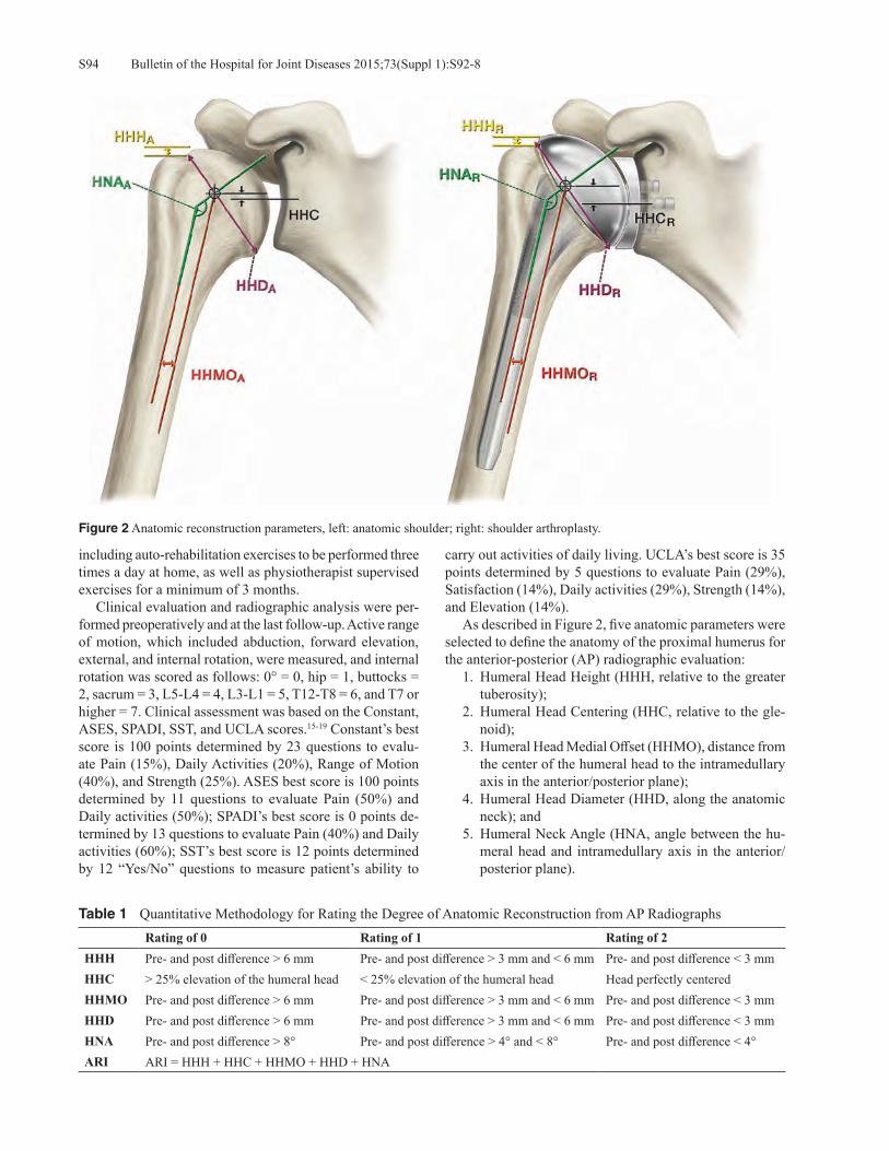
Bulletin of the Hospital for Joint Diseases 2015;73(Suppl 1):S92-8S94
including auto-rehabilitation exercises to be performed three times a day at home, as well as physiotherapist supervised exercises for a minimum of 3 months. Clinical evaluation and radiographic analysis were per-formed preoperatively and at the last follow-up. Active range of motion, which included abduction, forward elevation, external, and internal rotation, were measured, and internal rotation was scored as follows: 0° = 0, hip = 1, buttocks = 2, sacrum = 3, L5-L4 = 4, L3-L1 = 5, T12-T8 = 6, and T7 or higher = 7. Clinical assessment was based on the Constant, ASES, SPADI, SST, and UCLA scores.15-19 Constant’s best score is 100 points determined by 23 questions to evalu-ate Pain (15%), Daily Activities (20%), Range of Motion (40%), and Strength (25%). ASES best score is 100 points determined by 11 questions to evaluate Pain (50%) and Daily activities (50%); SPADI’s best score is 0 points de-termined by 13 questions to evaluate Pain (40%) and Daily activities (60%); SST’s best score is 12 points determined by 12 “Yes/No” questions to measure patient’s ability to
carry out activities of daily living. UCLA’s best score is 35 points determined by 5 questions to evaluate Pain (29%), Satisfaction (14%), Daily activities (29%), Strength (14%), and Elevation (14%). As described in Figure 2, five anatomic parameters were selected to define the anatomy of the proximal humerus for the anterior-posterior (AP) radiographic evaluation: 1. Humeral Head Height (HHH, relative to the greater
tuberosity); 2. Humeral Head Centering (HHC, relative to the gle-
noid); 3. Humeral Head Medial Offset (HHMO), distance from
the center of the humeral head to the intramedullary axis in the anterior/posterior plane);
4. Humeral Head Diameter (HHD, along the anatomic neck); and
5. Humeral Neck Angle (HNA, angle between the hu-meral head and intramedullary axis in the anterior/posterior plane).
Figure 2 Anatomic reconstruction parameters, left: anatomic shoulder; right: shoulder arthroplasty.
Table 1 Quantitative Methodology for Rating the Degree of Anatomic Reconstruction from AP RadiographsRating of 0 Rating of 1 Rating of 2
HHH Pre- and post difference > 6 mm Pre- and post difference > 3 mm and < 6 mm Pre- and post difference < 3 mmHHC > 25% elevation of the humeral head < 25% elevation of the humeral head Head perfectly centeredHHMO Pre- and post difference > 6 mm Pre- and post difference > 3 mm and < 6 mm Pre- and post difference < 3 mmHHD Pre- and post difference > 6 mm Pre- and post difference > 3 mm and < 6 mm Pre- and post difference < 3 mmHNA Pre- and post difference > 8° Pre- and post difference > 4° and < 8° Pre- and post difference < 4°ARI ARI = HHH + HHC + HHMO + HHD + HNA
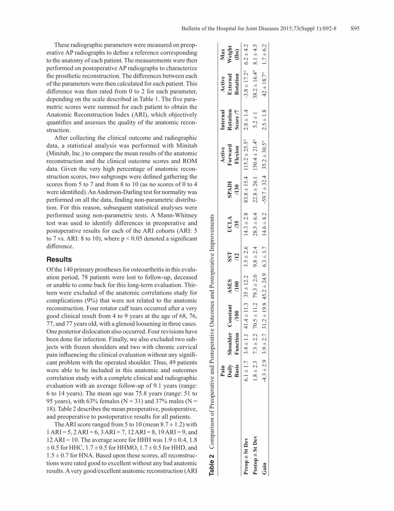
S95Bulletin of the Hospital for Joint Diseases 2015;73(Suppl 1):S92-8
These radiographic parameters were measured on preop-erative AP radiographs to define a reference corresponding to the anatomy of each patient. The measurements were then performed on postoperative AP radiographs to characterize the prosthetic reconstruction. The differences between each of the parameters were then calculated for each patient. This difference was then rated from 0 to 2 for each parameter, depending on the scale described in Table 1. The five para-metric scores were summed for each patient to obtain the Anatomic Reconstruction Index (ARI), which objectively quantifies and assesses the quality of the anatomic recon-struction. After collecting the clinical outcome and radiographic data, a statistical analysis was performed with Minitab (Minitab, Inc.) to compare the mean results of the anatomic reconstruction and the clinical outcome scores and ROM data. Given the very high percentage of anatomic recon-struction scores, two subgroups were defined gathering the scores from 5 to 7 and from 8 to 10 (as no scores of 0 to 4 were identified). An Anderson-Darling test for normality was performed on all the data, finding non-parametric distribu-tion. For this reason, subsequent statistical analyses were performed using non-parametric tests. A Mann-Whitney test was used to identify differences in preoperative and postoperative results for each of the ARI cohorts (ARI: 5 to 7 vs. ARI: 8 to 10), where p < 0.05 denoted a significant difference.
ResultsOf the 140 primary prostheses for osteoarthritis in this evalu-ation period, 78 patients were lost to follow-up, deceased or unable to come back for this long-term evaluation. Thir-teen were excluded of the anatomic correlations study for complications (9%) that were not related to the anatomic reconstruction. Four rotator cuff tears occurred after a very good clinical result from 4 to 9 years at the age of 68, 76, 77, and 77 years old, with a glenoid loosening in three cases. One posterior dislocation also occurred. Four revisions have been done for infection. Finally, we also excluded two sub-jects with frozen shoulders and two with chronic cervical pain influencing the clinical evaluation without any signifi-cant problem with the operated shoulder. Thus, 49 patients were able to be included in this anatomic and outcomes correlation study with a complete clinical and radiographic evaluation with an average follow-up of 9.1 years (range: 6 to 14 years). The mean age was 75.8 years (range: 51 to 95 years), with 63% females (N = 31) and 37% males (N = 18). Table 2 describes the mean preoperative, postoperative, and preoperative to postoperative results for all patients. The ARI score ranged from 5 to 10 (mean 8.7 ± 1.2) with 1 ARI = 5, 2 ARI = 6, 3 ARI = 7, 12 ARI = 8, 19 ARI = 9, and 12 ARI = 10. The average score for HHH was 1.9 ± 0.4, 1.8 ± 0.5 for HHC, 1.7 ± 0.5 for HHMO, 1.7 ± 0.5 for HHD, and 1.5 ± 0.7 for HNA. Based upon these scores, all reconstruc-tions were rated good to excellent without any bad anatomic results. A very good/excellent anatomic reconstruction (ARI Ta
ble
2
Com
paris
on o
f Pre
oper
ativ
e an
d Po
stop
erat
ive
Out
com
es a
nd P
osto
pera
tive
Impr
ovem
ents
Pain
D
aily
B
asis
Shou
lder
Fu
nctio
nC
onst
ant
/100
ASE
S/1
00SS
T/1
2U
CL
A/3
5SP
AD
I/1
30
Act
ive
Forw
ard
Flex
ion
Inte
rnal
R
otat
ion
Scor
e /7
Act
ive
Ext
erna
l R
otat
ion
Max
W
eigh
t (lb
s)Pr
eop
± St
Dev
6.1
± 1.
73.
4 ±
1.1
41.4
± 1
1.3
35 ±
12.
23.
5 ±
2.6
14.3
± 2
.883
.8 ±
15.
411
5.2
± 25
.5°
2.8
± 1.
4-3
.8 ±
17.
2°6.
2 ±
4.2
Post
op ±
St D
ev1.
8 ±
2.3
7.3
± 2.
270
.5 ±
11.
279
.3 ±
2.0
9.8
± 2.
428
.5 ±
6.4
22.8
± 2
6.1
150.
4 ±
21.4
°5.
2 ±
138
.2 ±
16.
4°8.
1 ±
4.5
Gai
n -4
.3 ±
2.9
3.9
± 2.
731
.2 ±
19.
845
.2 ±
24.
96.
3 ±
3.7
14.6
± 8
.2-5
9.7
± 32
.435
.2 ±
30.
5°2.
5 ±
1.8
42 ±
18.
7°1.
7 ±
6.2
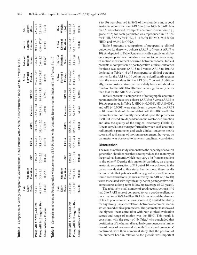
Bulletin of the Hospital for Joint Diseases 2015;73(Suppl 1):S92-8S96
8 to 10) was observed in 86% of the shoulders and a good anatomic reconstruction (ARI 5 to 7) in 14%. No ARI less than 5 was observed. Complete anatomic restoration (e.g., grade of 2) for each parameter was reproduced in 87.8 % for HHH, 87.8 % for HHC, 71.4 % for HHMO, 75.5 % for HHD, and 69.4% for HNA. Table 3 presents a comparison of preoperative clinical outcomes for these two cohorts (ARI 5 to 7 versus ARI 8 to 10). As depicted in Table 3, no statistically significant differ-ence in preoperative clinical outcome metric score or range of motion measurement occurred between cohorts. Table 4 presents a comparison of postoperative clinical outcomes for these two cohorts (ARI 5 to 7 versus ARI 8 to 10). As depicted in Table 4, 4 of 5 postoperative clinical outcome metrics for the ARI 8 to 10 cohort were significantly greater than the mean values for the ARI 5 to 7 cohort. Addition-ally, mean postoperative pain on a daily basis and shoulder function for the ARI 8 to 10 cohort were significantly better than that for the ARI 5 to 7 cohort. Table 5 presents a comparison of radiographic anatomic parameters for these two cohorts (ARI 5 to 7 versus ARI 8 to 10). As presented in Table 5, HHC (< 0.0001), HNA (0.008), and ARI (< 0.0001) were significantly greater for the ARI 8 to 10 cohort. It should be noted that both the HHC and HNA parameters are not directly dependent upon the prosthesis itself but instead are dependent on the rotator cuff function and also the quality of the surgical osteotomy (Table 4). Linear correlations were performed between each anatomic radiographic parameter and each clinical outcome metric score and each range of motion measurement; however, no parameter was observed to have a strong linear correlation.
DiscussionThe results of this study demonstrate the capacity of a fourth generation shoulder prosthesis to reproduce the anatomy of the proximal humerus, which may vary a lot from one patient to the other.20 Despite this anatomic variation, an average anatomic reconstruction of 8.7 out of 10 was achieved in the patients evaluated in this study. Furthermore, these results demonstrate that patients with very good to excellent ana-tomic reconstructions (as measured by an ARI of 8 to 10) were associated with significantly better postoperative out-come scores at long-term follow-up (average of 9.1 years). The relatively small number of good reconstruction (14% had 5 to 7 ARI scores) compared to very good/excellent re-constructions (86% had 8 to 10 ARI scores) and the absence of fair to poor reconstructions (scores < 5) limited the ability for any strong linear correlations between anatomical recon-struction and clinical parameters. The parameter that showed the highest linear correlation with both clinical evaluation scores and range of motion was the HHC. This result is consistent with the study of Nyffeler,7 who concluded that positioning of the humeral head had consequences in limita-tion of range of motion and strength. Terrier and coworkers9
confirmed, with their numerical study, that the position of the humeral head in relation to the glenoid was important Ta
ble
3
Com
paris
on o
f Ave
rage
Pre
oper
ativ
e M
easu
rem
ents
, aTS
A P
atie
nts w
ith A
nato
mic
Rec
onst
ruct
ion
Inde
x of
5 to
7 V
ersu
s 8 to
10
Pain
D
aily
B
asis
Shou
lder
Fu
nctio
nSS
TU
CL
AA
SES
Con
stan
tSP
AD
I
Act
ive
Forw
ard
Flex
ion
Inte
rnal
R
otat
ion
Scor
e
Act
ive
Ext
erna
l R
otat
ion
Max
W
eigh
t (lb
s)Pr
eop
AR
I 5-7
Avg
± S
t Dev
7.2
± 1.
13.
0 ±
0.6
3.0
± 2.
512
.7 ±
2.1
30.0
± 9
.638
.5 ±
12.
188
.5 ±
10.
696
.7 ±
18.
6°3.
2 ±
1.3
0.0
± 6.
3°7.
5 ±
5.2
Preo
p A
RI 8
-10
Avg
± St
Dev
6.1
± 1.
73.
3 ±
1.1
3.3
± 2.
314
.1 ±
2.7
34.4
± 1
2.2
40.2
± 9
.584
.8 ±
15.
511
5.6
± 24
.6°
2.6
± 1.
5-5
.9 ±
17.
8°6.
1 ±
3.6
Man
n-W
hitn
ey P
-val
ue0.
1572
0.55
230.
8049
0.25
730.
4712
0.49
300.
6953
0.05
780.
3366
0.26
050.
4630
Tab
le 4
C
ompa
rison
of A
vera
ge P
osto
pera
tive
Mea
sure
men
ts, a
TSA
Pat
ient
s with
Ana
tom
ic R
econ
stru
ctio
n In
dex
of 5
to 7
Ver
sus 8
to 1
0
Pain
D
aily
B
asis
Shou
lder
Fu
nctio
nSS
TU
CL
AA
SES
Con
stan
tSP
AD
I
Act
ive
Forw
ard
Flex
ion
Inte
rnal
R
otat
ion
Scor
e
Act
ive
Ext
erna
l R
otat
ion
Max
W
eigh
t (lb
s)Po
stop
AR
I 5-7
Avg
± S
t Dev
3.5
± 3.
05.
7 ±
2.7
8.0
± 1.
823
.8 ±
8.5
65.8
± 1
8.1
63.3
± 9
.441
.3 ±
25.
814
1.7
± 27
.9°
5.5
± 1.
144
.2 ±
14.
6°5.
8 ±
3.8
Post
op A
RI 8
-10
Avg
± St
Dev
1.1
± 1.
87.
8 ±
1.9
10.5
± 1
.930
.3 ±
4.9
85.0
± 1
6.6
74.2
± 7
.215
.3 ±
20.
215
4.4
± 16
.7°
5.4
± 1.
037
.2 ±
16.
3°9.
0 ±
4.3
Man
n-W
hitn
ey P
-val
ue0.
0341
0.04
800.
0044
0.06
540.
0138
0.01
230.
0084
0.34
430.
7259
0.16
400.
0980

S97Bulletin of the Hospital for Joint Diseases 2015;73(Suppl 1):S92-8
Table 5 Comparison of Anatomic Reconstruction Parameters, Patients with ARI of 5 to 7 Versus 8 to 10Humeral
Head Height Score
Centering of Humeral
Head
Medial Humeral
Head Offset
Humeral Head
Diameter
Humeral Head
Neck Angle
Anatomic Reconstruction
IndexIndex 5-7 Avg ± St Dev 1.7 ± 0.8 1.2 ± 0.8 1.3 ± 0.8 1.7 ± 0.5 0.5 ± 0.8 6.3 ± 0.8Index 8-10 Avg ± St Dev 1.9 ± 0.3 1.9 ± 0.3 1.7 ± 0.4 1.7 ± 0.5 1.7 ± 0.6 9.0 ± 0.8Mann-Whitney P-value 0.6484 < 0.0001 0.1565 0.6388 0.0008 < 0.0001
in restoring mobility and minimizing the risk of loosening. Clinical parameters, such as pain and shoulder function, were related to the quality of reconstruction, but it was not possible to clearly highlight the correlation with strength and mobility even though the average measures of strength and elevation trended better in the 8 to 10 ARI cohort. This observation may be related to the small number of patients in the ARI 5 to 8 cohort, but it corresponds to the precepts of Neer, constantly confirmed in the literature thereafter, that the quality of clinical results and specifically strength and active mobility depend on the status of the rotator cuff. Although having excluded secondary cuff tears from our study, the function of the rotator cuff deteriorating over time can influence the results of a study like this with an average follow-up of 9 years. This study has some limitations. One single surgeon performed every procedure and scored the results; while this increases the uniformity of the data and method, it may also limit the generalizability of the results. Future work should incorporate a larger database to include multiple surgeons and multiple sites using the same prosthesis to confirm these conclusions. Additionally, this study is limited by the use of 2D assessments from standard AP radiographs. This method can be further refined by the use of 3D quantita-tive assessment of each parameter, including continuous measurements rather than discrete categories to improve precision. To this end, future work should incorporate the use of 3D CT reconstructions instead of AP radiographs. In their 3D analysis cadaveric study of 65 shoulders, Walch and Boileau10 concluded that third generation anatomic prosthe-sis, by allowing a correct reconstruction of the joint, better restored normal glenohumeral anatomy and kinematics. Other limitations include the lack of independent review in the radiographic scoring.
ConclusionThis study confirmed Neer’s concept by demonstrating that an improved anatomic reconstruction results in better postoperative clinical outcomes as measured by 4 of the 5 clinical metrics. The fourth generation prosthesis used for this study allows continuous in-situ adjustment of the humeral head orientation through use of the spherical taper on the replicator plate and also a double adjustment of offset through the use of the offset humeral head and offset taper on the replicator plate. The quality of implantation and the status of the rotator cuff in an aging population may influence the results, which reinforces the need for sharing experience
and specialized training for indications and implantations of anatomical total shoulder prostheses.
Conflict of Interest StatementPierre-Henri Flurin, M.D., Thomas W. Wright, M.D., and Joseph D. Zuckerman, M.D., are consultants for and receives royalties from Exactech, Inc., Gainesville, Florida. Christo-pher P. Roche, M.S., M.B.A., is an employee of Exactech, Inc., Gainesville, Florida.
References1. Neer CS II. Replacement arthroplasty for gleno-humeral
osteoarthritis. J Bone Joint Surg Am. 1974 Jan;56(1):1-13. 2. Neer CS II, Watson KC, Stanton FJ. Recent experience in
total shoulder replacement. J Bone Joint Surg Am. 1982 Mar;64(3):319-37.
3. Boileau P, Sinnerton RJ, Chuinard C, Walch G. Arthroplasty of the shoulder. J Bone Joint Surg Br. 2006 May;88(5):562-75.
4. Moskal MJ, Duckworth D, Matsen FA. An analysis of 122 failed shoulder arthroplasties (abstract). J Shoulder Elbow Surg. 1999;8:554.
5. Roche C, Angibaud L, Flurin PH, et al. Anatomic valida-tion of an “Anatomical” shoulder system. Bull Hosp Jt Dis. 2006;63(3-4):93-7.
6. Godeneche A, Boileau P, Favard L, et al. Prosthetic re-placement in the treatment of osteoarthritis of the shoulder. Early results of 268 cases. J Shoulder Elbow Surg. 2002 Jan-Feb;11(1):11-8.
7. Nyffeler R, Sheikh R, Jacob HA, Gerber C. Influence of Hu-meral Prosthesis Height on Biomechanics of Glenohumeral Abduction. J Bone Joint Surg Am. 2004 Mar;86-A(3):575-80.
8. Pearl. M, Kurutz S. Geometric Analysis of Commonly Used Prosthetic Systems for Proximal Humeral Replacement. J Bone Joint Surg Am. 1999 May;81(5):660-71.
9. Terrier A, Ramondetti S, Merlini F, et al. Biomechanical consequences of humeral component malpositioning after anatomical shoulder arthroplasty. J Shoulder Elbow Surg. 2010 Dec;19(8):1184-90.
10. Walch G, Boileau P. Prosthetic adaptability: A new concept for shoulder arthroplasty. J Shoulder Elbow Surg. 1999 Sep-Oct;8(5):443-51.
11. Buchler P, Farron A. Benefits of an anatomical reconstruc-tion of the humeral head during shoulder arthroplasty: a finite element analysis. Clin Biomech (Bristol, Avon). 2004 Jan;19(1):16-23.
12. Edwards T, Kadakia NR, Boulahia A, et al. A Comparison of hemiarthroplasty and total shoulder arthroplasty in the treatment of primary glenohumeral osteoarthritis: Results of a multicenter study. J Shoulder Elbow Surg. 2003 May-Jun;12(3):207-13.
Bulletin of the Hospital for Joint Diseases 2015;73(Suppl 1):S92-8S98
13. Favard L. Revision of total shoulder arthroplasty. Orthop Traumatol Surg Res. 2013 Feb;99(1 Suppl):S12-21.
14. Flurin P-H, Gregory T, Wright T, et al. Assessment of the Relationship Between Anatomic Reconstruction and Clinical Outcome Using the Equinoxe Shoulder Arthroplasty System. Available at: http://www.exac.com/resource-library/shoulder/reference-papers/assessment-of-the-relationship-between-anatomic-recontruction-and-clinical-outcome-using-the-equinoxe-total-shoulder-arthroplasty-system.
15. Constant CR, Murley AH. A Clinical Method of Functional Assessment of the Shoulder. Clin Orthop Relat Res. 1987 Jan;(214):160-4.
16. Richards RR, An KN, Bigliani LU, et al. A standardized method for the assessment of shoulder function. J Shoulder Elbow Surg. 1994 Nov;3(6):347-52.
17. Roach KE, Budiman-Mak E, Songsiridej N, Lertratanakul Y. Development of a shoulder pain and disability index. Arthritis Care Res. 1991 Dec;4(4):143-9.
18. Lippitt SB, et al. A practical tool for evaluating function: The Simple Shoulder Test. In: MatsenFA, Fu FH, Hawkins RJ (eds): The Shoulder: A Balance of Mobility and Stability. Rosemont, IL: American Academy of Orthopaedic Surgeons. 1992, pp. 501-518.
19. Amstutz HC, Sew Hoy AL, Clarke IC. UCLA anatomic total shoulder arthroplasty. Clin Orthop. 1981 Mar-Apr;(155):7-20.
20. Boileau P, Walch G. The Three-Dimensional Geometry of the Proximal Humerus. Implications for surgical technique and prosthetic design. J Bone Joint Surg (Br). 1997 Sep;79(5):857-65.
S99Bulletin of the Hospital for Joint Diseases 2015;73(Suppl 1):S99-106
Mau E, Roche CP, Zuckerman JD. Effects of body mass index on outcomes in total shoulder arthroplasty. Bull Hosp Jt Dis. 2015;73(Suppl 1):S99-106.
Abstract
Body Mass Index (BMI) is one of the metrics used to assess overall health and has been implicated in having predictive value in many aspects of health, including outcomes after shoulder replacement surgery. Outcome data from a multi-institutional database with an average follow-up period of 39.8 months (minimum 24-months) demonstrated that all patients, regardless of BMI, improved significantly after treatment with anatomic total shoulder arthroplasty (aTSA) or reverse total shoulder arthroplasty (rTSA). Improvements in outcomes were stratified and compared based upon BMI in three groups: less than 25, 25 to 35, and greater than 35. Comparing these measures demonstrated that aTSA patients with higher BMI were generally associated with lower functional postoperative outcome metric scores than aTSA patients with lower BMI, though the preoperative to postoperative gains were generally equivalent regardless of BMI. Interestingly, postoperative outcome metric scores with rTSA patients were equivalent regardless of BMI as were the pre-to-postoperative gains. Additionally, differences in the magnitude of pre-to-postoperative improvement of range of motion (ROM) measurements between patients of BMI less than 25 and BMI greater than 35 were noted for forward flexion, internal rotation, and active and passive external rotation. The actual clinical significance of these differences is unknown. Finally, patients with lower BMI appeared to have a higher incidence of low-grade scapular notching.
Over 33% of adults over 60 years of age in the USA were reported to be obese in a national study per-formed by the CDC in 2011 to 2012.1 Among this
population, many will undergo shoulder replacement surgery for various indications, including osteoarthritis, rheumatoid arthritis, and proximal humerus fracture. National rates of shoulder arthroplasty have markedly increased over the past two decades, with one study finding a two and half fold increase in this procedure between 2000 to 2008.2 Thus, as obesity has moved to the forefront as a public health issue, questions related to its effects on commonly performed or-thopaedic procedures, such as shoulder replacement surgery, have become increasingly important. The literature on the effects of body mass index (BMI) on outcomes in shoulder arthroplasty has had heterogeneous findings. One recent study of 119 patients reported increased complications after reverse shoulder arthroplasty (rTSA) in patients with BMI less than 25 and BMI greater than 35 when compared against those with BMI 25 to 35.3 These findings were similar to those reported by Beck and coworkers4 and Lindberg and associates,5 whereby obese patients in both studies of 76 and 45 patients, respectively, had significantly more complications than those of normal BMI despite gains in function for both groups postoperatively. Another study of 77 patients undergoing anatomic total shoulder arthroplasty (aTSA) reported no overall physical functional improve-ments postoperatively as reflected on SF-36 scores for obese patients in comparison to patients with normal BMIs.6 At the same time, many studies have reported contrary find-ings, with a lack of evidence supporting the notion that BMI has any negative impacts on outcomes after shoulder arthroplasty surgery.7-13
The purpose of our study was to use data gathered from a multi-institutional database to objectively assess the effects of BMI on clinical outcomes with both aTSA and rTSA using a single platform shoulder system.
Effects of Body Mass Index on Outcomes in Total Shoulder Arthroplasty
Elaine Mau, M.Sc., M.D., F.R.C.S.C., Christopher P. Roche, M.S., M.B.A., and Joseph D. Zuckerman, M.D.
Elaine Mau, M.Sc., M.D., F.R.C.S.C., French Bay Orthopaedics, Ellsworth, Maine. Christopher P. Roche, M.S., M.B.A., Exactech, Inc., Gainesville, Florida. Joseph D. Zuckerman, M.D., Department of Orthopaedic Surgery, Hospital for Joint Diseases, NYU Langone Medical Center, New York, New York. Correspondence: Christopher P. Roche, M.S., M.B.A., Exactech, Inc., 2320 NW 66th Court, Gainesville, Florida 32653; [email protected].

Bulletin of the Hospital for Joint Diseases 2015;73(Suppl 1):S99-106S100
Materials and MethodsData acquisition and analysis was performed with approval from the Western Institutional Review Board (IRB), protocol # WIRB 20091701. The data was stripped of all individual subject identifiers and pooled for the following analysis. Preoperative and postoperative data was analyzed from 1,111 patients (69.2 ± 8.8 years) treated by 12 orthopaedic surgeons using either aTSA or rTSA with one platform shoulder system (Equinoxe®, Exactech, Inc., Gainesville, Florida). Four hundred ninety-nine patients received an aTSA (66.0 ± 8.9 years; 265 female, 234 male) for the treat-ment of degenerative arthritis, and 612 patients received a rTSA (71.8 ± 7.9 years; 389 female, 223 male) for the treatment of rotator cuff arthropathy and osteoarthritis. Each patient was scored preoperatively and at latest follow-up us-ing the SST, UCLA, ASES, Constant, and SPADI metrics; additionally, active abduction, forward flexion, and active and passive external rotation (ER) with the arm at the side were measured by their surgeons upon follow-up. Internal rotation (IR) was measured by vertebral segments and was scored by the following discrete assignment: 0° = 0, hip = 1, buttocks = 2, sacrum = 3, L5-L4 = 4, L3-L1 = 5, T12-T8 = 6, and T7 or higher = 7. Anderson-Darling test for normality was performed on the above data, and found non-parametric distribution of the data. For this reason, subsequent statistical analysis was carried out using non-parametric tests. A Mann-Whitney test was used to identify differences in preoperative, postoperative, and pre-to-postoperative improvements in results for aTSA and rTSA patients sorted into three different BMI groups: less than 25, 25 to 35, and greater 35, where p < 0.05 denoted a significant difference. Characteristics of the comparison groups were as follows: the average follow-up for all patients was 39.8 ± 18.7 months (aTSA: 43.1 ± 21.9 months; rTSA: 37.1 ± 15.1 months). Regarding the aTSA patients, 110 patients had a BMI less than 25 (79 female, 31 male) with an average age of 68.1 ± 9.8 years and an average follow-up of 43.9 ± 21.2 months. Two hundred ninety patients had a BMI greater than 25 and less than 35 (134 female, 156 male) with an average age of 66.0 ± 8.9 years and an average follow-up of 43.4 ± 22.5 months. Ninety-nine patients had a BMI greater than 35 (52 female, 47 male) with an average age = 63.7 ± 7.2 years and an average follow-up of 41.3 ± 21.3 months. For rTSA patients, 196 patients had a BMI less than 25 (138 female, 58 male) with an average age of 73.5 ± 7.7 years and an average follow-up of 36.4 ± 15.1 months. Three hundred fifty-seven patients had a BMI greater than 25 and less than 35 (217 female, 140 male) with an average age of 71.3 ± 7.7 years and an average follow-up of 37.5 ± 15.3 months. Fifty-nine patients had a BMI greater than 35 (34 female, 25 male) with an average age of 68.9 ± 8.6 years and an average follow-up of 36.2 ± 14.2 months. Among the rTSA group, preoperative and postoperative data was further analyzed in regards to scapular notching. Data from 415 patients (average age: 72.2 ± 7.2 years; range, 50 to 90 years) who received primary rTSA with a minimum of
2-years outcome (average follow-up = 38.1 ± 16.4 months) was examined. Three hundred sixty-three patients (221 female, average: 72.9 years; 132 male, average: 70.6 years) had no scapular notch (age = 72.1 ± 7.2 years), whereas 52 patients (33 female, average: 74.8 years; 19 male, average: 70.6 years) had a scapular notch (age = 73.3 ± 7.6 years). The average follow-up for rTSA patients without a scapular notch was 37.2 ± 16.0 months, and the average follow-up for rTSA patients with a scapular notch was 44.4 ± 17.9 months. Scapular notching was graded using the Nerot-Sirveaux classification system for postoperative notching.14
ResultsAll patients demonstrated overall improvements in range of motion (ROM), pain, and function following treatment with aTSA and rTSA, although to varying degrees. Table 1 presents a comparison of average preoperative measure-ments between aTSA patients with BMI less than 25, BMI between 25 and 35, and BMI greater than 35. Table 2 pres-ents a comparison of average postoperative measurements between aTSA patients with BMI less than 25, BMI between 25 and 35, and BMI greater than 35. Table 3 presents a comparison of average pre-to-postoperative improvement in measurements between aTSA patients with BMI less than 25, BMI between 25 and 35, and BMI greater than 35. Table 4 presents a comparison of average preopera-tive measurements between rTSA patients with BMI less than 25, BMI between 25 and 35, and BMI greater than 35. Table 5 presents a comparison of average postopera-tive measurements between rTSA patients with BMI less than 25, BMI between 25 and 35, and BMI greater than 35. Table 6 presents a comparison of average preoperative to postoperative improvement in measurements between rTSA patients with BMI less than 25, BMI between 25 and 35, and BMI greater than 35.
ROMFor patients undergoing aTSA, two of the five baseline preoperative ROM measurements were significantly worse for patients with greater than 35 BMI than for patients with less than 25 BMI, namely active forward flexion and IR. Postoperatively, three of the five ROM measurements were also significantly worse for patients with greater than 35 BMI than for patients with less than 25 BMI; these were IR, active ER, and passive ER. However, when compar-ing the mean preoperative to postoperative improvement in measurements between patients with less than 25 BMI and patients with greater than 35 BMI, there were largely no significant differences in the magnitude of improvement between the two groups except for IR and active forward flexion: patients with BMI greater than 35 had significantly less improvement in internal rotation; patients with BMI greater than 35 also had a statistically significantly gain in forward flexion than those with BMI less than 25. When comparing differences in ROM measurements between the BMI 25 to 35 group with the other BMI groups, the BMI less

S101Bulletin of the Hospital for Joint Diseases 2015;73(Suppl 1):S99-106
Tab
le 1
C
ompa
rison
of A
vera
ge P
reop
erat
ive
Mea
sure
men
ts, a
TSA
Pat
ient
s BM
I Gre
ater
than
25,
BM
I Bet
wee
n 25
to 3
5, a
nd B
MI G
reat
er th
an 3
5
SST
UC
LA
ASE
SC
onst
ant
SPA
DI
Act
ive
Abd
uctio
n
Act
ive
Forw
ard
Flex
ion
Inte
rnal
R
otat
ion
Scor
e
Act
ive
Ext
erna
l R
otat
ion
Pass
ive
Ext
erna
l R
otat
ion
Max
W
eigh
t (lb
s)Pr
eop
BM
I < 2
5 Av
g ±
St D
ev4.
3 ±
2.6
14.8
± 3
.740
.0 ±
15.
039
.2 ±
14.
179
.0 ±
19.
183
.5 ±
28.
0°10
0.3
± 33
.5°
3.3
± 1.
617
.2 ±
19.
9°25
.7 ±
20.
6°2.
2 ±
4.0
Preo
p B
MI 2
5 to
35
Avg
± St
Dev
3.8
± 2.
714
.6 ±
3.9
38.5
± 1
2.6
37.8
± 1
2.6
80.6
± 2
1.8
80.2
± 2
7.1°
95.8
± 3
0.6°
2.8
± 1.
516
.2 ±
19.
9°23
.7 ±
21.
5°2.
7 ±
4.0
Preo
p B
MI >
35
Avg
± St
Dev
3.0
± 2.
812
.8 ±
4.3
31.1
± 1
5.8
31.0
± 1
1.6
90.0
± 2
1.3
77.4
± 2
5.7°
88.7
± 2
7.3°
2.7
± 1.
414
.2 ±
17.
1°20
.3 ±
17.
2°1.
7 ±
3.6
Man
n-W
hitn
eyP-
valu
e <
25 v
s. >
350.
0004
0.00
180.
0003
0.00
010.
0006
0.13
120.
0037
0.00
710.
3173
0.08
930.
2499
Man
n-W
hitn
eyP-
valu
e <
25 v
s. 25
to 3
50.
1086
0.57
930.
3263
0.55
860.
4899
0.34
860.
1828
0.00
230.
6861
0.36
380.
2246
Man
n-W
hitn
eyP-
valu
e 25
to 3
5 vs
. > 3
50.
0073
0.00
110.
0011
< 0
.000
10.
0018
0.35
030.
0198
0.82
760.
4044
0.27
460.
0207
Tab
le 2
C
ompa
rison
of A
vera
ge P
osto
pera
tive
Mea
sure
men
ts, a
TSA
Pat
ient
s BM
I Les
s tha
n 25
, BM
I Bet
wee
n 25
to 3
5, a
nd B
MI G
reat
er th
an 3
5
SST
UC
LA
ASE
SC
onst
ant
SPA
DI
Act
ive
Abd
uctio
n
Act
ive
Forw
ard
Flex
ion
Inte
rnal
R
otat
ion
Scor
e
Act
ive
Ext
erna
l R
otat
ion
Pass
ive
Ext
erna
l R
otat
ion
Max
W
eigh
t (lb
s)Po
stop
BM
I < 2
5 Av
g ±
St D
ev10
.5 ±
2.2
31.3
± 5
.187
.4 ±
17.
773
.1 ±
12.
513
.8 ±
20.
412
2.9
± 29
.8°
144.
4 ±
30.8
°5.
7 ±
1.2
50.2
± 2
0.6°
58.6
± 1
9.1°
6.7
± 5.
6Po
stop
BM
I 25
to 3
5 Av
g ±
St D
ev10
.4 ±
2.4
30.1
± 6
.084
.2 ±
19.
971
.2 ±
15.
118
.4 ±
24.
912
0.1
± 30
.2°
139.
9 ±
32.0
°5.
2 ±
1.4
45.7
± 2
0.4°
54.5
± 2
1.1°
7.8
± 5.
8Po
stop
BM
I > 3
5 Av
g ±
St D
ev10
.0 ±
2.8
30.2
± 5
.781
.2 ±
21.
467
.9 ±
17.
422
.1 ±
26.
111
6.2
± 31
.9°
141.
2 ±
34.2
°4.
4 ±
1.6
42.6
± 1
9.7°
49.8
± 2
0.4°
6.8
± 6.
1M
ann-
Whi
tney
P-va
lue
< 25
vs.
> 35
0.21
760.
1513
0.00
640.
0253
0.00
190.
1564
0.46
94 <
0.0
001
0.00
360.
0025
0.98
18
Man
n-W
hitn
eyP-
valu
e <
25 v
s. 25
to 3
50.
7933
0.04
930.
2806
0.58
280.
1333
0.56
080.
1763
0.00
030.
0300
0.06
330.
0656
Man
n-W
hitn
eyP-
valu
e 25
to 3
5 vs
. > 3
50.
0960
0.90
940.
0444
0.04
630.
0161
0.26
090.
6144
< 0
.000
10.
3331
0.09
430.
0986
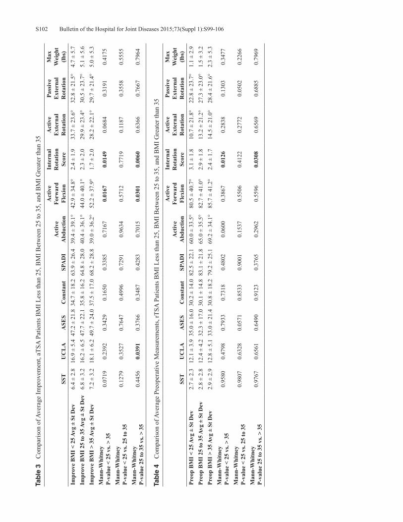
Bulletin of the Hospital for Joint Diseases 2015;73(Suppl 1):S99-106S102Ta
ble
3
Com
paris
on o
f Ave
rage
Impr
ovem
ent,
aTSA
Pat
ient
s BM
I Les
s tha
n 25
, BM
I Bet
wee
n 25
to 3
5, a
nd B
MI G
reat
er th
an 3
5
SST
UC
LA
ASE
SC
onst
ant
SPA
DI
Act
ive
Abd
uctio
n
Act
ive
Forw
ard
Flex
ion
Inte
rnal
R
otat
ion
Scor
e
Act
ive
Ext
erna
l R
otat
ion
Pass
ive
Ext
erna
l R
otat
ion
Max
W
eigh
t (lb
s)Im
prov
e B
MI <
25
Avg
± St
Dev
6.4
± 2.
816
.9 ±
5.4
47.2
± 2
1.8
34.7
± 1
8.2
63.9
± 2
6.4
39.4
± 3
9.1°
42.9
± 3
4.8°
2.4
± 1.
933
.7 ±
23.
6°32
.8 ±
21.
5°4.
7 ±
5.7
Impr
ove
BM
I 25
to 3
5 Av
g ±
St D
ev6.
8 ±
3.2
16.2
± 6
.547
.7 ±
22.
135
.8 ±
16.
264
.8 ±
28.
040
.4 ±
36.
1°44
.0 ±
40.
1°2.
3 ±
2.0
29.9
± 2
3.4°
30.5
± 2
3.7°
5.1
± 5.
6Im
prov
e B
MI >
35
Avg
± St
Dev
7.2
± 3.
218
.1 ±
6.2
49.7
± 2
4.0
37.5
± 1
7.0
68.2
± 2
8.8
39.0
± 3
6.2°
52.2
± 3
7.9°
1.7
± 2.
028
.2 ±
22.
1°29
.7 ±
21.
4°5.
0 ±
5.3
Man
n-W
hitn
eyP-
valu
e <
25 v
s. >
350.
0719
0.23
920.
3429
0.16
500.
3385
0.71
670.
0167
0.01
490.
0684
0.31
910.
4175
Man
n-W
hitn
eyP-
valu
e <
25 v
s. 25
to 3
50.
1279
0.35
270.
7647
0.49
960.
7291
0.96
340.
5712
0.77
190.
1187
0.35
580.
5555
Man
n-W
hitn
eyP-
valu
e 25
to 3
5 vs
. > 3
50.
4456
0.03
910.
3766
0.34
870.
4283
0.70
150.
0301
0.00
600.
6366
0.76
670.
7964
Tab
le 4
C
ompa
rison
of A
vera
ge P
reop
erat
ive
Mea
sure
men
ts, r
TSA
Pat
ient
s BM
I Les
s tha
n 25
, BM
I Bet
wee
n 25
to 3
5, a
nd B
MI G
reat
er th
an 3
5
SST
UC
LA
ASE
SC
onst
ant
SPA
DI
Act
ive
Abd
uctio
n
Act
ive
Forw
ard
Flex
ion
Inte
rnal
R
otat
ion
Scor
e
Act
ive
Ext
erna
l R
otat
ion
Pass
ive
Ext
erna
l R
otat
ion
Max
W
eigh
t (lb
s)Pr
eop
BM
I < 2
5 Av
g ±
St D
ev2.
7 ±
2.3
12.1
± 3
.935
.0 ±
16.
030
.2 ±
14.
082
.5 ±
22.
160
.0 ±
33.
5°80
.5 ±
40.
7°3.
1 ±
1.8
10.7
± 2
1.8°
22.8
± 2
3.7°
1.1
± 2.
9Pr
eop
BM
I 25
to 3
5 Av
g ±
St D
ev2.
8 ±
2.8
12.4
± 4
.232
.3 ±
17.
030
.1 ±
14.
883
.1 ±
21.
865
.0 ±
35.
5°82
.7 ±
41.
0°2.
9 ±
1.8
13.2
± 2
1.2°
27.3
± 2
3.0°
1.5
± 3.
2Pr
eop
BM
I > 3
5 Av
g ±
St D
ev2.
9 ±
2.9
12.8
± 5
.133
.0 ±
21.
430
.8 ±
18.
279
.2 ±
25.
169
.2 ±
34.
1°85
.7 ±
41.
2°2.
4 ±
1.7
14.5
± 2
1.0°
28.4
± 2
1.6°
2.3
± 5.
3M
ann-
Whi
tney
P-va
lue
< 25
vs.
> 35
0.95
800.
4798
0.79
330.
7318
0.48
020.
0600
0.38
670.
0126
0.28
380.
1303
0.34
77
Man
n-W
hitn
eyP-
valu
e <
25 v
s. 25
to 3
50.
9807
0.63
280.
0571
0.85
330.
9001
0.15
370.
5506
0.41
220.
2772
0.05
020.
2266
Man
n-W
hitn
eyP-
valu
e 25
to 3
5 vs
. > 3
50.
9767
0.65
610.
6490
0.91
230.
3765
0.29
620.
5596
0.03
080.
6569
0.68
850.
7969

S103Bulletin of the Hospital for Joint Diseases 2015;73(Suppl 1):S99-106
Tab
le 5
C
ompa
rison
of A
vera
ge P
osto
pera
tive
Mea
sure
men
ts, r
TSA
Pat
ient
s BM
I Les
s tha
n 25
, BM
I Bet
wee
n 25
to 3
5, a
nd B
MI G
reat
er th
an 3
5
SST
UC
LA
ASE
SC
onst
ant
SPA
DI
Act
ive
Abd
uctio
n
Act
ive
Forw
ard
Flex
ion
Inte
rnal
R
otat
ion
Scor
e
Act
ive
Ext
erna
l R
otat
ion
Pass
ive
Ext
erna
l R
otat
ion
Max
W
eigh
t (lb
s)Po
stop
BM
I < 2
5 Av
g ±
St D
ev10
.0 ±
2.4
30.1
± 5
.284
.3 ±
17.
371
.1 ±
14.
420
.2 ±
23.
810
2.7
± 24
.9°
140.
4 ±
26.0
°4.
9 ±
1.4
32.3
± 1
3.1°
43.7
± 1
4.2°
9.3
± 7.
5Po
stop
BM
I 25
to 3
5 Av
g ±
St D
ev9.
9 ±
2.6
30.3
± 4
.984
.4 ±
17.
371
.5 ±
15.
221
.5 ±
24.
810
6.1
± 26
.0°
139.
6 ±
28.4
°4.
5 ±
1.7
32.8
± 1
6.2°
47.1
± 1
5.8°
9.7
± 8.
2Po
stop
BM
I > 3
5 Av
g ±
St D
ev10
.3 ±
2.2
30.5
± 4
.986
.0 ±
15.
372
.2 ±
15.
119
.9 ±
20.
410
5.7
± 25
.7°
132.
6 ±
32.6
°4.
0 ±
1.7
31.1
± 1
4.2°
46.2
± 1
4.8°
11.6
± 9
.2M
ann-
Whi
tney
P-va
lue
< 25
vs.
> 35
0.37
870.
4687
0.48
720.
6977
0.63
680.
9600
0.18
900.
0007
0.43
840.
3220
0.22
97
Man
n-W
hitn
eyP-
valu
e <
25 v
s. 25
to 3
50.
8377
0.49
630.
5458
0.68
650.
7990
0.31
360.
9974
0.04
350.
5064
0.01
320.
8449
Man
n-W
hitn
eyP-
valu
e 25
to 3
5 vs
. > 3
50.
3239
0.71
300.
7415
0.83
900.
7820
0.63
880.
1638
0.03
260.
2293
0.50
820.
2603
Tab
le 6
C
ompa
rison
of A
vera
ge Im
prov
emen
t, rT
SA P
atie
nts B
MI L
ess t
han
25, B
MI B
etw
een
25 to
35,
and
BM
I Gre
ater
than
35
SST
UC
LA
ASE
SC
onst
ant
SPA
DI
Act
ive
Abd
uctio
n
Act
ive
Forw
ard
Flex
ion
Inte
rnal
R
otat
ion
Scor
e
Act
ive
Ext
erna
l R
otat
ion
Pass
ive
Ext
erna
l R
otat
ion
Max
W
eigh
t (lb
s)Im
prov
e B
MI <
25
Avg
± St
Dev
7.4
± 3.
018
.1 ±
6.0
49.4
± 2
0.6
41.6
± 1
9.5
61.6
± 2
5.8
42.4
± 3
7.1°
59.9
± 4
5.7°
1.8
± 2.
021
.3 ±
23.
1°20
.0 ±
24.
1°8.
6 ±
7.4
Impr
ove
BM
I 25
to 3
5 Av
g ±
St D
ev7.
2 ±
3.3
18.1
± 6
.352
.4 ±
21.
742
.0 ±
20.
061
.6 ±
27.
541
.5 ±
36.
6°56
.7 ±
46.
2°1.
6 ±
2.0
20.0
± 2
3.2°
19.4
± 2
3.6°
8.6
± 7.
8Im
prov
e B
MI >
35
Avg
± St
Dev
7.3
± 3.
517
.5 ±
6.8
52.0
± 2
4.8
41.3
± 2
4.5
57.5
± 2
6.2
36.3
± 3
2.4°
45.1
± 4
3.7°
1.5
± 2.
015
.7 ±
23.
6°17
.9 ±
23.
1°9.
3 ±
9.9
Man
n-W
hitn
eyP-
valu
e <
25 v
s. >
350.
8103
0.45
110.
5648
0.92
750.
4574
0.26
550.
0105
0.27
970.
1727
0.42
040.
7453
Man
n-W
hitn
eyP-
valu
e <
25 v
s. 25
to 3
50.
7779
0.91
240.
0934
0.79
920.
7813
0.96
410.
3334
0.22
630.
8340
0.86
930.
6683
Man
n-W
hitn
eyP-
valu
e 25
to 3
5 vs
. > 3
50.
6961
0.51
800.
7775
0.74
990.
3166
0.22
790.
0327
0.72
170.
2107
0.49
570.
5834

Bulletin of the Hospital for Joint Diseases 2015;73(Suppl 1):S99-106S104
than 25 group had significantly greater preoperative IR, and the BMI greater than 35 group had significantly less active forward flexion. This was also true of their absolute post-operative IR measurement. However, when improvements in ROM were examined, there was no difference between the BMI less than 25 group and BMI 25 to 35 group in any of the ROM dimensions analyzed. The BMI greater than 35 group had two out of the five ROM scores differ; namely, they had significantly more gains in active forward flexion and significantly less gains in IR compared to the BMI 25 to 35 group; the lack of any significant linear relationship between BMI and ROM was also illustrated with a correla-tion analysis where r values failed to reach significance for all the ROM dimensions measured across all BMIs. For rTSA patients, no significant difference was noted in all ROM dimensions measured except for IR, when com-paring absolute preoperative ROM or postoperative ROM measurements between those with BMI less than 25 and those with BMI greater than 35. Indeed, IR was the only ROM measurement found to be significantly worse both preoperatively and postoperatively for patients with BMI greater than 35 as compared to patients with BMI less than 25. However, when examining the average improvement in ROM preoperatively versus postoperatively for these two groups, again there were no significant differences in their gains in ROM except for in active forward flexion where the group with BMI less than 25 improved significantly more (average improvement of 59.9 ± 45.7°) than the group with BMI greater than 35 (average improvement of 45.1 ± 43.7°). When data from BMI 25 to 35 group was compared against the other BMI groups undergoing rTSA, although there were few significant differences between the absolute measurements preoperatively (IR for the BMI greater than 35 group was significantly less at their preoperative visits compared to BMI 25 to 35 group) and postoperatively (IR and passive ER for the BMI less than 25 group and IR for the BMI greater than 35 group), there were no significant differences in gains of ROM for most of the five ROM mea-surements for either the BMI less than 25 or BMI greater than 35 group when compared to the BMI 25 to 35 group at final follow-up, except in active forward flexion for those with BMI greater than 35.
Functional Outcomes ScoresFor aTSA patients, all five of the preoperative functional outcome scores were significantly worse for patients with BMI greater than 35 as compared patients with BMI less than 25. Postoperatively, three of the five postoperative functional outcome measurements were significantly lower in patients with BMI greater than 35 than for those with BMI less than 25, namely the ASES, Constant-Murley, and SPADI scores. However, when comparing their mean change in improve-ment, there were no significant differences in their improved clinical outcome scores between those with BMI less than 25 and those with BMI greater than 35. When comparing the differences in functional outcome scores between the
BMI 25 to 35 group against those of the other BMI cohorts undergoing aTSA, it was found that there were no significant differences in preoperative or postoperative scores for those with BMI less than 25; nor were there any significant differ-ences in the average gains in functional scores after surgery for the BMI less than 25 group compared to the group with BMI 25 to 35. However, the group with BMI greater than 35 did have all five preoperative functional measurements differ significantly from those baseline values measured in the BMI 25 to 35 group. Their postoperative functional scores were not significantly different, though, in any of the five ROM categories, and comparison of the average improvement in functional scores only revealed a significant difference in the UCLA score when those with BMI greater than 35 were compared against those with BMI 25 to 35. For patients undergoing rTSA, those with BMI less than 25 when compared with those with BMI greater than 35 had no significant differences in their absolute preoperative scores, absolute postoperative scores, or in the average im-provement in each score from preoperative to postoperative assessment. All five functional scoring methods improved for those BMI less than 25 or those BMI greater than 35, such that there was no significant difference in their scores. When comparing the BMI less than 25 and BMI greater than 35 groups undergoing rTSA with those having BMI between 25 to 35, again there were no differences between their absolute preoperative scores, no significant differences between their absolute postoperative scores, and no significant different findings in their average improvement for each of the five respective functional scores analyzed.
Scapular NotchingIn regards to scapular notching, rTSA patients with BMI less than 25, radiographic follow-up was available for 137 patients (70%); 22 patients had a scapular notch (16.1%) and an average scapular notching grade of 0.23. For the rTSA patients with BMI greater than 25 and less than 35, radio-graphic follow-up was available for 241 patients (68%); 28 patients had a scapular notch (11.6%) and an average scapu-lar notching grade of 0.15. For the rTSA patients with BMI greater than 35, radiographic follow-up was available for 34 patients (58%); one patient had a scapular notch (2.9%) and an average scapular notching grade of 0.03.
DiscussionThe results of this study demonstrate that all patients, regardless of BMI, improved significantly after treatment with an aTSA or rTSA. A comparison of outcome measures demonstrated that aTSA patients with higher BMI were generally associated with lower functional postoperative outcome metric scores than aTSA patients with lower BMI, though the preoperative to postoperative gains were gener-ally equivalent regardless of BMI. Interestingly, absolute postoperative outcome metric scores with rTSA patients were equivalent regardless of BMI as were the preoperative to postoperative gains.

S105Bulletin of the Hospital for Joint Diseases 2015;73(Suppl 1):S99-106
This data supports the notion that patients with any BMI can benefit from a total shoulder replacement and achieve significant gains in ROM, pain, and function. This is similar to the findings of Beck and coworkers.4 While one might postulate that greater restrictions may be imposed by a larger soft tissue envelope, such that uniformly all gains in ROM would be less for those with a greater BMI, our data on average preoperative to postoperative gains in ROM did not support this hypothesis for either aTSA or rTSA. For aTSA, while there were smaller gains in IR after surgery for the patients with increasing BMI groups, there were also greater gains in active forward flexion with increasing BMI. While the average improvement in IR for those with BMI less than 25 is 2.4 ± 1.9 versus 1.7 ± 2.0 for those with BMI greater than 35 is significant; however, whether a 0.7 difference in IR score translates into a clinically important difference despite the statistical difference in these mea-surements is unclear. Forward flexion similarly was found to be different for patients undergoing aTSA and rTSA, depending on their BMI groups, but it is uncertain whether the absolute difference in improvements will translate into a clinically significant difference. For instance, an average improvement of 49.2° ± 34.8° in active forward flexion was achieved by those with BMI less than 25 undergoing aTSA compared to an average improvement of 52.2° ± 37.9° for those with BMI greater than 35. Yet, some studies in the literature have suggested that a minimum of 11° to 16° in ROM is needed to translate to a clinically important differ-ence given the subjectivity involved with measuring ROM even with a goniometer.15 Similarly, the absolute magnitude of difference for the few differences in ROM were within this reported minimum range. Analysis of the functional outcome scores also revealed few significant differences between outcome measure scores for patients of any BMI group, particularly for rTSA in which no differences were observed in any BMI group at any time point. For those undergoing aTSA, only the UCLA was found to have any difference when comparing average improvements between those groups studied and only when comparing patients with BMI between 25 to 35 and those with BMI greater than 35. None of the other functional scores showed any significant differences in their average preopera-tive to postoperative gains when comparing between groups of varying BMIs. It is notable that among all the outcome measures examined in this study, the UCLA score has been described as being the most poorly characterized measure in validity, reliability, and responsiveness compared to the other measures of outcomes16 and in this study it was the only measure that was found to be any different between the two groups. Overall, the majority of the findings in this study support the notion that patients of all BMIs can benefit from treatment of either type of shoulder replacement. A difference in the relative occurrence of scapular notching was noted between the BMI groups, with patients having a lower BMI being associated with a larger scapular notching rate and grade and patients with greater BMI being
associated with a smaller scapular notching rate and grade. We suspect that this increased scapular notching rate and grade speaks to both the increased activity level of lower BMI patients but also the increased ROM as patients with thinner arms can achieve greater adduction and bring the arm closer to their torso. This was similar to the findings reported by Falaise and colleagues17 who also noted that thinner patients had greater adduction of their arms second-ary to fewer soft tissue impingements, which in turn was correlated with higher cut angles off the humeral head and subsequently higher glenometaphyseal angles which were found to correlate with greater notching in their studies. Strengths of the current study design include the multi-institutional nature of the database and the involvement of multiple surgeons, potentially allowing greater generaliz-ability of the results across varying surgical techniques and experience. A variety of scoring instruments were used to assess functional improvement in order to mitigate the shortcoming of any one scoring system. For instance, Roy and associates18 found that the ASES and SPADI scoring instruments were better than the SST in assessing clini-cally detectable changes over time, and both the ASES and SPADI have a known minimal quantity that correlates with a clinically important change in the patient (6.4 and 8, re-spectively), whereas this value is not known for the SST. On the other hand, the SST scoring system was found to have a higher level of reliability, providing more consistency in its results. Also, for both functional outcome scores and ROM, comparisons in improvement were performed, examining the difference in preoperative to postoperative ROM and functional outcome scores rather than comparing absolute scores. This allowed preoperative to serve as an internal control with regard to baseline differences in absolute mea-surements. Limitations in study design include the multi-institutional nature of the database study and the lack of independent evaluation at follow-up; surgeons were performing their own assessments at follow-up, potentially leading to a bias for higher ROM scores even in assessments where soft tissue envelopes may obscure accurate measuring. No inter- or intra-observer reliability analyses were carried out. As well, data was collected using a single shoulder system, and thus the ability to generalize to other shoulder system designs may be limited. Furthermore, any differences that may be present during the early recovery phase and how this varies across BMI groups may not be captured in this study given the minimum 2-year follow-up used.
Conclusions These study results support the notion that the benefits of shoulder arthroplasty appear to extend to patients with a wide range of BMI, given that the other characteristics of patient selection for surgery are satisfied. Although having a BMI in the recommended range may benefit many other aspects of a patient’s overall health that would in turn affect their recovery and overall function, this study demonstrates that

Bulletin of the Hospital for Joint Diseases 2015;73(Suppl 1):S99-106S106
those who are classified as obese achieved similar gains in clinical metric scores and ROM as those with lower BMI with both aTSA and rTSA.
Disclosure Statement Elaine Mau, M.Sc., M.D., F.R.C.S.C., has no conflict of interest to report. Christopher P. Roche, M.S., M.B.A., is an employee of Exactech, Inc., Gainesville, Florida. Joseph D. Zuckerman, M.D., is a consultant for Exactech, Inc., and receives royalties on products related to this article.
References1. Ogden C, Carroll MD, Kit BK, Flegal KM. Prevalence of
obesity among adults: United States, 2011-2012. NCHS Data Brief. 2013;Oct (131):1-8.
2. Kim SH, Wise BL, Zhang Y, Szabo RM. Increasing incidence of shoulder arthroplasty in the United States. J Bone Joint Surg Am. 2011 Dec 21;93(24):2249-54.
3. Gupta AK, Chalmers PN, Rahman Z, et al. Reverse total shoulder arthroplasty in patients of varying body mass index. J Shoulder Elbow Surg. 2014 Jan;23(1):35-42.
4. Beck JD, Irgit KS, Andreychik CM, et al. Reverse total shoulder arthroplasty in obese patients. J Hand Surg Am. 2013 May;38(5):965-70.
5. Linberg CJ, Sperling JW, Schleck CD, Cofield RH. Shoulder arthroplasty in morbidly obese patients. J Shoulder Elbow Surg. 2009 Nov-Dec;18(6):903-6.
6. Li X, Williams PN, Nguyen JT, et al. Functional outcomes after total shoulder arthroplasty in obese patients. J Bone Joint Surg Am. 2013 Nov;95(21):e160.
7. Chalmers PN, Gupta AK, Rahman Z, et al. Predictors of early complications of total shoulder arthroplasty. J Arthroplasty. 201Apr;29(4):856-60.
8. Richards J, Inacio MC, Beckett M, et al. Patient and procedure-specific risk factors for deep infection after primary shoulder arthroplasty. Clin Orthop Relat Res. 2014 Sep;472(9):2809-15.
9. Linberg CJ, Sperling JW, Schleck CD, Cofield RH. Shoulder arthroplasty in morbidly obese patients. J Shoulder Elbow Surg. 2009 Nov-Dec;18(6):903-6.
10. Li X, Williams P, Trivellas A, et al. Functional outcome after total shoulder arthroplasty in the obese patient population: a prospective study with greater than 2 years of follow up. J Bone Joint Surg Br. 2013;95(21):e1601-8.
11. Waterman BR, Dunn JC, Bader J, et al. Thirty-day morbidity and mortality after elective total shoulder arthroplasty: patient-based and surgical risk factors. J Shoulder Elbow Surg. 2015 Jan;24(1):24-30.
12. Pappou I, Virani NA, Clark R, et al. Outcomes and costs of reverse shoulder arthroplasty in the morbidly obese: a case control study. J Bone Joint Surg Am. 2014 Jul;96(14):1169-76.
13. Griffin JW, Novicoff WM, Browne JA, Brockmeiser SF. Mor-bid obesity in total shoulder arthroplasty: risk, outcomes, and cost analysis. J Shoulder Elbow Surg. 2014 Oct;23(10):1444-8.
14. Sirveaux F, Favard L, Oudet D, et al. Grammont inverted total shoulder arthroplasty in the treatment of glenohumeral osteoarthritis with massive rupture of the cuff: results of a multicenter study of 80 shoulders. J Bone Joint Surg Br. 2004 Apr;86(3):388-95.
15. Muir SW, Corea CL, Beaupre L. Evaluating change in clinical status: reliability and measures of agreement for the assess-ment of glenohumeral range of motion. N Am J Sports Phys Ther. 2010 Sep;5(3):98-110.
16. Wylie JD, Beckman JT, Granger E, Tashjian RZ. Functional outcomes assessment in shoulder surgery. World J Orthop. 2014 Nov 18;5(5):623-33.
17. Falaise V, Levigne C, Favard L. Scapular notching in reverse shoulder arthroplasties: the influence of glenome-taphyseal angle. Orthop Traumatol Surg Res. 2011 Oct;97(6 Suppl):S131-7.
18. Roy JS, MacDermid JC, Woodhouse LJ. Measuring shoulder function: a systematic review of four questionnaires. Arthritis Rheum. 2009 May;61(5):623-32.

S107Bulletin of the Hospital for Joint Diseases 2015;73(Suppl 1):S107-10
Broder K, Christiano A, Zuckerman JD, Egol K. Management of proximal humerus fractures with the Equinoxe® locking plate system. Bull Hosp Jt Dis. 2015;73(Suppl 1):S107-10.
Abstract
There is no consensus on surgical fixation and treatment of proximal humerus fractures, even though they are common fractures with several fixation techniques. This retrospective study quantifies the outcomes of patients who sustained a proximal humerus fracture and were treated with open re-duction and internal fixation by at a single academic center between December 2010 and December 2014 using the Equi-noxe® proximal humerus locking plate. Following enrollment, injury and surgical data was recorded. Forty-nine patients (31 female, 18 male) with 50 fractures were identified who met the inclusion criteria. Mean follow-up period was 16.8 months (range: 6 to 44 months). Mean age was 60.7 years with no significant difference in mean age by gender. Mean age-adjusted Charlson Comorbidity Index (CCI) was 2.9 (range: 0 to 6). The overall complication rate was 10% (N = 5) with the most common complication being osteonecrosis (N = 3). Four patients required reoperation. At final follow-up, mean active forward flexion for the cohort was 140.8º ± 30.1º, mean passive forward flexion was 155.7º ± 25.2º, and mean active external rotation was 50.1º ± 17.9º. For patients with postoperative complications, mean active forward flexion was 106.0º ± 23.0º, mean passive forward flexion was 136.7º ± 23.1º, and mean active external rotation was 34.2º ± 24.4. Active forward flexion and external rotation were significantly different in the presence of a complication (p = 0.005 and p = 0.038, respectively). Mean DASH score for the cohort was
19.1 ± 20.9. Mean DASH score for patients who developed complications or underwent reoperations was 34.2 ± 24.3. This study demonstrates that the Equinoxe® proximal humerus locking plate provides stable fracture treatment with excellent clinical results and a low complication rate when performed by experienced orthopaedic traumatologists.
Fractures of the proximal humerus comprise approxi-mately 5% of all fractures with between 300,000 to 700,000 reported cases per year.1-3 These fractures
occur commonly as a result of a low energy fall in patients with poor bone quality.1 Over 70% of proximal humerus in-juries occur in patients 60 years and older, overwhelmingly in women over men, with a 3:1 predominance.4 With our population rapidly aging, orthopaedic surgeons in the USA should anticipate a three-fold increase in proximal humerus fractures within the next 30 years.4,5 Already, the rate of proximal humerus fracture operative treatment increased by 25.6% from 1999 to 2005.6,7 These facts underscore the importance of care of proximal humerus fractures, as well as the method of fixation when operative treatment is se-lected. However, there is still no consensus in the literature concerning the optimal management of these injuries, due to high rates of complications, such as osteonecrosis (ON) and screw penetration and also due to the variety of implants and surgical techniques available that are utilized for fracture fixa-tion.7-10 Options for treatment include percutaneous pinning, intramedullary nailing, locking plates, hemiarthroplasty, or reverse total shoulder arthroplasty, each offering advantages and disadvantages.8,11 Locking plates have been a significant improvement in proximal humerus fracture fixation, as they potentially maintain anatomical alignment and stable fixation, especially in osteoporotic bone.8 While one study has analyzed one company’s proximal humerus locking plate, the Proximal Humerus Internal Locking System (PHILOS), there have not been detailed examinations of other implant types.12 In 2010,
Kari Broder, B.A., Anthony Christiano, B.A., Joseph D. Zucker-man, M.D., and Kenneth Egol, M.D., Department of Orthopaedic Surgery, Hospital for Joint Diseases, NYU Langone Medical Center, New York, New York.Correspondence: Kenneth Egol, M.D., Department of Orthopae-dic Surgery, Hospital for Joint Diseases, NYU Langone Medical Center, 301 East 17th Street, New York, New York 10003; [email protected].
Management of Proximal Humerus Fractures with the Equinoxe® Locking Plate System
Kari Broder, B.A., Anthony Christiano, B.A., Joseph D. Zuckerman, M.D., and Kenneth Egol, M.D.

Bulletin of the Hospital for Joint Diseases 2015;73(Suppl 1):S107-10S108
Exactech, Inc., (Gainesville, FL) released the Equinoxe®
proximal humerus locking plate with several new improve-ments on existing locking plate designs. The purpose of this study is to present the patient outcomes and complication rates of 55 consecutive proximal humerus fractures treated with the Equinoxe® proximal humerus locking plate.
MethodsThis retrospective study reports on the evaluation of patients who sustained a proximal humerus fractures and were treated by fellowship trained orthopaedic traumatologists at a single academic center between December 2010 and December 2014 using the Equinoxe® proximal humerus locking plate. The institution’s Institutional Review Board approved the study. All patients who underwent open reduction and in-ternal fixation (ORIF) with the Equinoxe® locking plate be-tween December 2010 and December 2014 were identified. Exclusion criteria included lack of complete functional data or follow-up less than 6 months. Fractures were classified according to the Neer classification.13 Surgical intervention was indicated for significantly displaced fractures and based upon the number of anatomic fragments. Surgeons experi-enced in the technique and implant performed all procedures. All surgeries were performed in the beach chair position. All patients were administered regional anesthesia, general anesthesia, or a combination of the both. The surgeries were performed via a deltopectoral or superolateral approach. The Equinoxe® proximal humerus locking plate was developed to restore the anatomy of the native shoulder, incorporating contours that correspond to the lateral humerus to increase fit and stability.14 The fracture plate system was introduced in the USA in 2010 and features a design that attempts to reduce humeral head collapse and improve outcomes for patients with suboptimal bone stock by maxi-mizing contact area. Additional features include the ability to deploy bone filler after plate seating, multiple screw and blade configurations, and a design to allow suture placement after the plate is secured (Fig. 1). Patients undergoing treatment with the Equinoxe® proximal humerus locking plate were followed at standard intervals using the Disabilities of the Arm, Shoulder, and Hand (DASH) questionnaire to assess functional outcome and with physical examination and radiographic examina-tion to determine clinical outcome or development of a complication at 3, 6, and 12 months after surgery and as available beyond 12 months.15 The DASH results in a score between 0 to 100 where 0 = no disability and 100 = extreme disability.16 Complications were also recorded, if present. Humeral head osteonecrosis (ON), surgical site infection, screw penetration, and heterotopic ossification limiting mo-bility were considered complications. Descriptive statistics were utilized to identify mean DASH scores, complication rates, and most prevalent complications among the data set. Student’s t-test were utilized to determine if DASH scores were statistically significantly related to Neer classification or presence of complication.
ResultsA total of 55 consecutive patients underwent proximal hu-merus repair with the Equinoxe® locking plate during the study period. Five patients were excluded from the study due to inadequate follow-up, and one patient was excluded due to concomitant fractures that affected extremity function. The remaining 49 patients with 50 fractures had a mean follow-up of 16.8 months (range: 6 to 44 months). Of the 49 patients, 31 (63%) were female and 18 (37%) were male, with a mean age of 60.7 ± 14.5 years (range: 25.9 to 87.7 years), with no significant difference in mean age by gender. The mean age-adjusted Charlson Comorbidity Index (CCI) was 2.85 (range: 0 to 6). The fracture classifications were: 19 (38%) two-part fractures, 18 (36%) three-part fractures, and 13 (26%) four-part fractures. The overall complication rate was 10% (N = 5). The most common complication was ON (N = 3; 6.0%) followed by infection, heterotopic ossification, and screw penetration (N = 1; 2.0% each) (Fig. 2). Four patients required reoperation (8.0%). Two patients underwent removal of hardware with irrigation and debridement for infection, one patient underwent removal of hardware for ON and screw penetration, and one patient underwent arthroscopic release for adhesive capsulitis. All patients healed radiographically with the exception of one patient who developed ON and infection and underwent subsequent removal of hardware. At latest follow-up, mean active forward flexion for the cohort was 140.8º ± 30.1º, mean passive forward flexion was 155.7º ± 25.2º, and mean active external rotation was 50.1º ± 17.9º.
Figure 1 The Equinoxe® fracture locking plate with (top) and without (bottom) blade (Exactech, Inc., Gainesville, FL).

S109Bulletin of the Hospital for Joint Diseases 2015;73(Suppl 1):S107-10
For patients with postoperative complications, mean active forward flexion was 106.0º ± 23.0º, mean passive forward flexion was 136.7º ± 23.1º, and mean active external rotation was 34.2º ± 24.4. Active forward flexion and external rotation were statistically significantly different in the presence of a complication (p = 0.005 and p = 0.038, respectively). Mean DASH score for the cohort was 19.1 ± 20.9. Mean DASH score for patients who developed complications and or un-derwent reoperations was 34.2 ± 24.3 (Fig. 3).
DiscussionWe found favorable clinical and functional outcomes with use of the Equinoxe® locking plate, with a safety profile compa-rable to any other plating system available on the market.10,12 The implant allowed for reliable fracture healing, early range of shoulder motion, and a low complication rate. The mean DASH score reported in this series corresponds to a high level of functionality in patients treated in this series. Surgical fixation of proximal humerus fractures should offer the opportunity for anatomic restoration, with the potential to meet the patient’s expectations of functionality and postoperative shoulder movement. All internal fixation techniques have strengths and weaknesses. Percutaneous pinning and nailing provide a minimally-invasive surgical method but offer less stability than other constructs, leading to high nonunion and malunion rates.17 While percutaneous pinning may be the least invasive method of operative fixation and therefore provides a theoretically lower chance of osteo-necrosis, it carries potential complications of pin migration and osteomyelitis.6,18 Intramedullary nailing may be useful in osteoporotic bone but has shown to have inferior stability
compared to plating and is associated with rotator cuff dys-function.18 Maier and coworkers6 demonstrated that nailing may be utilized for three-part and four-part fractures with either metaphyseal comminution or diaphyseal fracture with only minimal tuberosity displacement. Non-locked plates for proximal humerus fractures have fallen out of favor, especially in poor bone due to screw pullout and implant failure.5,8
Locking plates are considered the gold-standard implant for ORIF of the proximal humerus, due to their strength and rotational stability.2,19 One biomechanical study demonstrated that locking plates were less sensitive than other constructs to bone mineral density in the proximal humerus, making them a better choice for osteoporotic bone. The study also showed that, among intramedullary nail and plate constructs, locking plates offered the greatest stability, under both bending and torsional loading.20 This combination of strength and stabil-ity reduces the risk of failure that accompanies many other implants.2,20 The DASH score is considered a reliable and accurate method of ascertaining functionality and disability in the up-per extremity.16 A 2012 study of the PHILOS plate reported a mean DASH score of 36.12 In a review of all available proximal humerus locking plates currently in use, Sproul and colleagues10 identified an average DASH for patients of 26.6. By comparison, the patients in the present study had a mean DASH score of 19.1, potentially achieving full functionality in many instances. According to de Kruijf and associates,21 the highest functional outcome (DASH scores) for geriatric patients with proximal humerus fractures undergoing opera-tive treatment was achieved with the use of a locking plate, followed by intramedullary nail, and hemiarthroplasty.
Figure 2 Complication rates for our cohort of Equinoxe® locking plates versus literature-reported rates for all locking plates. Rates for ON, screw penetration, and reoperation were calculated as the averages of ranges put forth by multiple sources.4,10
Figure 3 Functional healing as assessed by the DASH score for the patients in our cohort with complications. A DASH score of less than 15 corresponds to “no problem,” a score between 15 to 60 “problem but working,” and a score of more than 60 “unable to work.”15
Bulletin of the Hospital for Joint Diseases 2015;73(Suppl 1):S107-10S110
Proximal humerus fracture ORIF is not without its share of complications. Osteonecrosis is most prevalent among Neer three-part and four-part fractures, with findings of 25% to 30% in percutaneous pinning and 3.1% to 16.4% prevalence in locking plate cohorts.4,10 ON can develop long after initial trauma and surgery, in some cases after 5 years.10 Correspond-ingly, results of ON, such as pain, joint arthritis, and decreased functionality, can take years to manifest, although in such cases ON is not an implant-related complication but rather a result of the fracture itself.10 Because locking plates do not rely on frictional forces, less soft tissue stripping is required for plate placement. This may be the explanation for lower ON rates seen with locked plates compared to historical series. Usually, intra-articular screw penetration occurs concomi-tantly with ON, as ON decreases bone quality and facilitates humeral head collapse leading to screw penetration.5 The prevalence of intra-articular screw penetration ranges from 7.5% to 23%.4,10 The complication rates with the Equinoxe® plates in our cohort are considerably lower than other lock-ing plates series in the literature.12 Our ON rate of 6% and screw pullout rate of 2.0% are markedly lower than rates for all locking plates and other methods of fracture repair.4,10
This study has some limitations. The cohort described in this study was treated by fellowship-trained traumatologists who had extensive knowledge of the Equinoxe® plate system and extensive surgical experience. It was a retrospective study without a control group. Many cases of ON can occur upwards of 5 years postoperatively. Since the implant has not been in clinical use for 5 years, we may see this reported rate increase with longer follow-up.
ConclusionWhile locking plate fixation pitfalls are well documented, including high complication rates and loss of reduction, the Equinoxe® proximal humerus locking plate, as reported in this study, provides excellent short-term clinical results with a low complication rate. Proximal humerus fracture fixation is and will continue to be an important skill in any orthopaedic traumatologist’s arsenal; additional and longer-term clinical follow-up is necessary to confirm these positive results.
Conflict of Interest StatementKari Broder, B.A., and Anthony Christiano, B.A., have no conflict of interest to report. Joseph D. Zuckerman, M.D., and Kenneth Egol, M.D., are consultants for Exactech, Inc. and receive royalties on products related to this article.
References1. Egol KA, Koval KJ, Zuckerman JD. Handbook of Fractures
(5th ed). Philadelphia: Wolters Kluwer/Lippincott Williams & Wilkins Health, 2015.
2. El-Sayed MMH. Surgical management of complex humerus head fractures. Orthop Rev (Pavia). 2010 Sep;2(2):e14.
3. Rangan A, Handoll H, Brealey S, et al. Surgical vs nonsurgical treatment of adults with displaced fractures of the proximal humerus. JAMA. 2015 Mar 10;313(10):1037-47.
4. Aaron D, Shatsky J, Paredes JC, et al. Proximal humeral
fractures: internal fixation. J Bone Joint Surg Am. 2012 Dec 19;94(24):2280-8.
5. Shulman BS, Egol KA. Open Reduction Internal Fixation for Proximal Humerus Fractures. Bull Hosp Jt Dis (2013). 2013;71 Suppl 2:54-9.
6. Maier D, Jaeger M, Izadpanah K, et al. Proximal humeral fracture treatment in adults. J Bone Joint Surg Am. 2014 Feb 5;96(3):251-61.
7. Petrigliano FA, Bezrukov N, Gamradt SC, SooHoo NF. Fac-tors predicting complication and reoperation rates following surgical fixation of proximal humeral fractures. J Bone Joint Surg Am. 2014 Sep 17;96(18):1544-51.
8. Erasmo R, Guerra G, Guerra L. Fractures and fracture-dislo-cations of the proximal humerus: A retrospective analysis of 82 cases treated with the Philos® locking plate. Injury. 2014 Dec;45 Suppl 6:S43-8.
9. Hauschild O, Konrad G, Audige L, et al. Operative versus non-operative treatment for two-part surgical neck fractures of the proximal humerus. Arch Orthop Trauma Surg. 2013 Oct;133(10):1385-93.
10. Sproul RC, Iyengar JJ, Devcic Z, Feeley BT. A systematic review of locking plate fixation of proximal humerus fractures. Injury. 2011 Apr;42(4):408-13.
11. Hong C, Hey H, Murphy D. Evolving trends in surgically man-aged patients with proximal humerus fracture: are we different after ten years? Singapore Med J. 2014 Nov;55(11):574-8.
12. Brunner A, Thormann S, Babst R. Minimally invasive per-cutaneous plating of proximal humeral shaft fractures with the Proximal Humerus Internal Locking System (PHILOS). J Shoulder Elbow Surg. 2012 Aug; 21(8):1056-63.
13. Neer CS. Displaced proximal humeral fractures. J Bone Joint Surg Am. 1970 Sep;52(6):1077-89.
14. Roche C, Angibaud L, Flurin PH, et al. Anatomic validation of an “anatomic” shoulder system. Bull Hosp Jt Dis. 2006;63(3-4):93-7.
15. Angst F, Schwyzer H-K, Aeschlimann A, et al. Measures of adult shoulder function: Disabilities of the Arm, Shoul-der, and Hand Questionnaire (DASH) and its short version (QuickDASH), Shoulder Pain and Disability Index (SPADI), American Shoulder and Elbow Surgeons (ASES) Society standardized shoulder. Arthritis Care Res (Hoboken). 2011 Nov;63 Suppl 1:S174-88.
16. Dowrick AS, Gabbe BJ, Williamson OD, Cameron PA. Out-come instruments for the assessment of the upper extremity following trauma: a review. Injury. 2005 Apr;36(4):468-76.
17. Cuny C, Goetzmann T, Dedome D, et al. Antegrade nailing evolution for proximal humeral fractures, the Telegraph IV®): a study of 67 patients. Eur J Orthop Surg Traumatol. 2015 Feb;25(2):287-95.
18. Vachtsevanos L. Management of proximal humerus fractures in adults. World J Orthop. 2014 Nov 15;5(5):685.
19. Jung S-W, Shim S-B, Kim H-M, et al. Factors that influence reduction loss in proximal humerus fracture surgery. J Orthop Trauma. 2015 Jun;29(6):276-82.
20. Siffri PC, Peindl RD, Coley ER, et al. Biomechanical analysis of blade plate versus locking plate fixation for a proximal humerus fracture: comparison using cadaveric and synthetic humeri. J Orthop Trauma. 2006 Sep;20(8):547-54.
21. de Kruijf M, Vroemen JP, de Leur K, et al. Proximal fractures of the humerus in patients older than 75 years of age: should we consider operative treatment? J Orthop Traumatol. 2014 Jun;15(2):111-5.
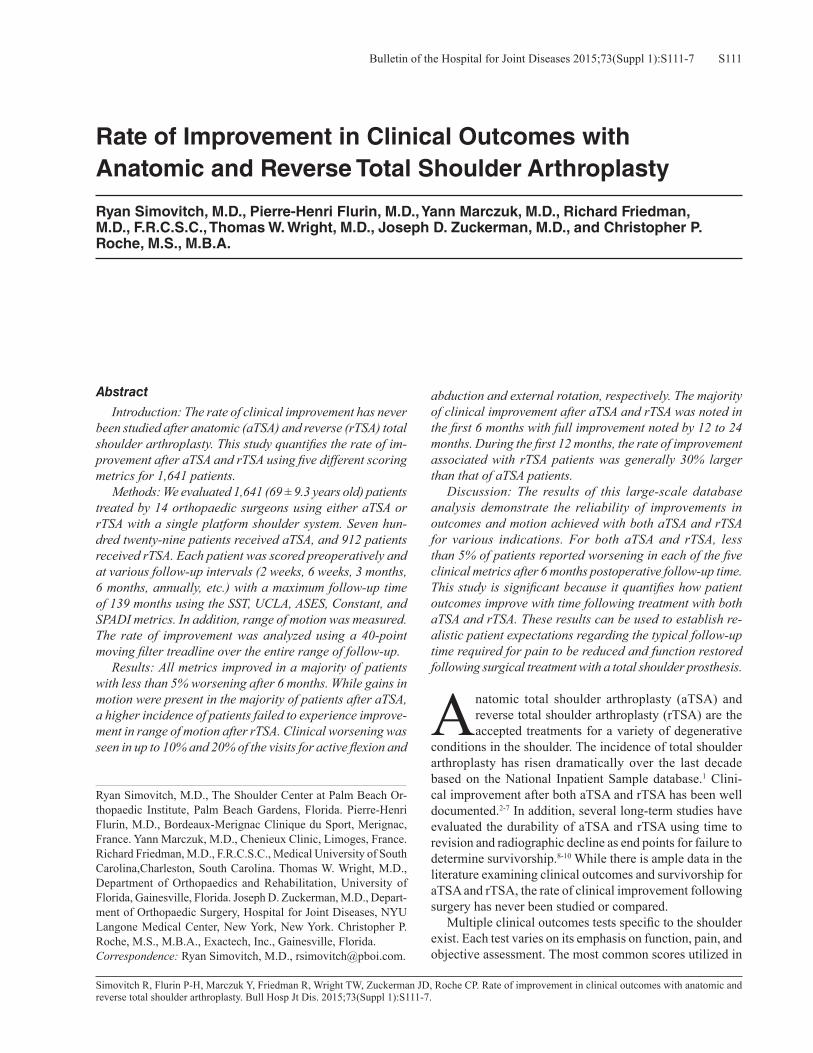
S111Bulletin of the Hospital for Joint Diseases 2015;73(Suppl 1):S111-7
Simovitch R, Flurin P-H, Marczuk Y, Friedman R, Wright TW, Zuckerman JD, Roche CP. Rate of improvement in clinical outcomes with anatomic and reverse total shoulder arthroplasty. Bull Hosp Jt Dis. 2015;73(Suppl 1):S111-7.
Abstract
Introduction: The rate of clinical improvement has never been studied after anatomic (aTSA) and reverse (rTSA) total shoulder arthroplasty. This study quantifies the rate of im-provement after aTSA and rTSA using five different scoring metrics for 1,641 patients. Methods: We evaluated 1,641 (69 ± 9.3 years old) patients treated by 14 orthopaedic surgeons using either aTSA or rTSA with a single platform shoulder system. Seven hun-dred twenty-nine patients received aTSA, and 912 patients received rTSA. Each patient was scored preoperatively and at various follow-up intervals (2 weeks, 6 weeks, 3 months, 6 months, annually, etc.) with a maximum follow-up time of 139 months using the SST, UCLA, ASES, Constant, and SPADI metrics. In addition, range of motion was measured. The rate of improvement was analyzed using a 40-point moving filter treadline over the entire range of follow-up. Results: All metrics improved in a majority of patients with less than 5% worsening after 6 months. While gains in motion were present in the majority of patients after aTSA, a higher incidence of patients failed to experience improve-ment in range of motion after rTSA. Clinical worsening was seen in up to 10% and 20% of the visits for active flexion and
abduction and external rotation, respectively. The majority of clinical improvement after aTSA and rTSA was noted in the first 6 months with full improvement noted by 12 to 24 months. During the first 12 months, the rate of improvement associated with rTSA patients was generally 30% larger than that of aTSA patients. Discussion: The results of this large-scale database analysis demonstrate the reliability of improvements in outcomes and motion achieved with both aTSA and rTSA for various indications. For both aTSA and rTSA, less than 5% of patients reported worsening in each of the five clinical metrics after 6 months postoperative follow-up time. This study is significant because it quantifies how patient outcomes improve with time following treatment with both aTSA and rTSA. These results can be used to establish re-alistic patient expectations regarding the typical follow-up time required for pain to be reduced and function restored following surgical treatment with a total shoulder prosthesis.
Anatomic total shoulder arthroplasty (aTSA) and reverse total shoulder arthroplasty (rTSA) are the accepted treatments for a variety of degenerative
conditions in the shoulder. The incidence of total shoulder arthroplasty has risen dramatically over the last decade based on the National Inpatient Sample database.1 Clini-cal improvement after both aTSA and rTSA has been well documented.2-7 In addition, several long-term studies have evaluated the durability of aTSA and rTSA using time to revision and radiographic decline as end points for failure to determine survivorship.8-10 While there is ample data in the literature examining clinical outcomes and survivorship for aTSA and rTSA, the rate of clinical improvement following surgery has never been studied or compared. Multiple clinical outcomes tests specific to the shoulder exist. Each test varies on its emphasis on function, pain, and objective assessment. The most common scores utilized in
Rate of Improvement in Clinical Outcomes with Anatomic and Reverse Total Shoulder Arthroplasty
Ryan Simovitch, M.D., Pierre-Henri Flurin, M.D., Yann Marczuk, M.D., Richard Friedman, M.D., F.R.C.S.C., Thomas W. Wright, M.D., Joseph D. Zuckerman, M.D., and Christopher P. Roche, M.S., M.B.A.
Ryan Simovitch, M.D., The Shoulder Center at Palm Beach Or-thopaedic Institute, Palm Beach Gardens, Florida. Pierre-Henri Flurin, M.D., Bordeaux-Merignac Clinique du Sport, Merignac, France. Yann Marczuk, M.D., Chenieux Clinic, Limoges, France. Richard Friedman, M.D., F.R.C.S.C., Medical University of South Carolina,Charleston, South Carolina. Thomas W. Wright, M.D., Department of Orthopaedics and Rehabilitation, University of Florida, Gainesville, Florida. Joseph D. Zuckerman, M.D., Depart-ment of Orthopaedic Surgery, Hospital for Joint Diseases, NYU Langone Medical Center, New York, New York. Christopher P. Roche, M.S., M.B.A., Exactech, Inc., Gainesville, Florida. Correspondence: Ryan Simovitch, M.D., [email protected].

Bulletin of the Hospital for Joint Diseases 2015;73(Suppl 1):S111-7S112
the USA include the Simple Shoulder Test (SST), University of California, Los Angeles (UCLA), American Shoulder and Elbow Surgeon (ASES), Constant, and Shoulder Pain and Disability Index (SPADI) metrics. The SST is composed of a series of 12 questions that assess function specific to work, sport, and activities of daily living (ADL) with a maximum score of 12. The UCLA metric has five questions that examine pain, range of motion, function, strength, and satisfaction with 60% of the responses subjective in nature; 35 is the maximum score. The ASES score is compiled from a series of 11 questions that reflect pain and function evenly with 100 being the maximum score. The Constant score is calculated from a series of 23 questions, 35% of which are dependent on subjective findings, while 65% depend on objective findings; 100 is the maximum score. The SPADI metric is calculated based on pain and function with 130 be-ing the maximum score, but 0 being the best value. Because each metric emphasizes function, pain, and objective find-ings differently, there can be variability within and between patients and the type of prosthesis. A better understanding of the rate of improvement as-sociated with aTSA and rTSA is critical to establish ac-curate expectations for reduction of pain and restoration of function. The setting of more realistic patient expectations
preoperatively will likely lead to greater patient satisfaction postoperatively. In addition, an understanding of the rate of improvement for each prosthesis type may allow surgeons to design different strategies of postoperative care for aTSA and rTSA patients. Furthermore, since studies typically employ a different cadre of metrics to assess outcome, it is imperative to understand how different metrics vary from each other. The purpose of this study is to quantify the rate of im-provement after aTSA and rTSA using five different scoring metrics for 1,641 patients using a single platform shoulder prosthesis. In order to achieve this, each follow-up visit was scored and compared to the prior visit beginning from the preoperative visit to the latest postoperative follow-up visit.
MethodsThe study group consisted of 1,641 patients treated by 14 orthopaedic surgeons using either an aTSA or rTSA with a single platform shoulder system (Equinoxe®, Exactech, Inc.; Gainesville, FL). These patients were prospectively enrolled in a multicenter database from November 2001 to April 2015. IRB approval was obtained. Average age was 69 ± 9 years. Maximum follow-up was 139 months. Seven hundred twenty-nine patients received an aTSA, and 912 patients received a rTSA. The average age of the aTSA
Table 1 Preoperative Diagnosis of aTSA and rTSA patients*aTSA rTSAN Diagnosis N Diagnosis653 OA 735 Cuff tear arthropathy5 RA 42 Acute fracture24 Post Capsuloraphy Arthropathy 36 Irreparable rotator cuff tear15 AVN 20 Fracture malunion or nonunion32 Post traumatic 18 Inflammatory arthropathy
15 Type B / C glenoid12 Failed ORIF proximal humerus fracture5 Chronic instability
*A small percentage of patients did not include an entry for preoperative diagnosis.
Table 2 Number of Data Points Obtained Within Each Time Interval for AnalysisFollow-up period aTSA rTSAPreoperative 729 912< 3 months 370 4643 to 6 months 308 3626 to 12 months 259 43612 to 24 months 307 51024 to 36 months 298 42836 to 48 months 129 21048 to 60 months 97 94> 60 months 83 84SUM 2,580 (1,851 postoperative) 3,500 (2,588 postoperative)

S113Bulletin of the Hospital for Joint Diseases 2015;73(Suppl 1):S111-7
group was 65 ± 9 years old while the average age of the rTSA group was 72 ± 8 years old. Fifty two percent (N = 384) of the aTSA patients were females while 48% (N = 345) were males. Sixty-five percent (N = 592) of the rTSA patients were females while 35% were males (N = 320). Preoperative diagnosis was varied and is recorded in Table 1. Each patient was prospectively evaluated preoperatively and then at regular intervals until their latest follow-up. Fol-low-up visits were typically at 2 weeks, 6 weeks, 3 months, 6 months, and annually thereafter. However, each patient did not have every time point visit in which case evaluation took place at the next possible time point. In order to be included in this study, each patient had to have at least two separate clinical evaluations (follow-up). Five metrics including SST, UCLA, ASES, Constant, and SPADI were recorded. In addition, active abduction, active forward flexion, and active and passive external rotation with the arm at the side were also measured. The difference between each follow-up value and the corresponding preoperative value was recorded as improvement and noted corresponding to its particular time point. A “negative improvement” value demonstrated clinical worsening while a “positive improvement” value demonstrated clinical improvement. These “improvements” once calculated were normalized to a 100 point scale to allow comparison between each scoring metric. A total of 1,851 postoperative follow-ups were entered into the database for aTSA, and a total of 2,588 postoperative follow-ups were entered into the database for rTSA for a total of 4,439 follow-up reports (Table 2). The rate of improvement was
analyzed using a 40-point moving filter treadline over the entire range of follow-up.
ResultsPositive improvement and clinical worsening relative to the preoperative value for each metric and range of motion were calculated for each follow-up visit. Based on this data, occurences of clinical worsening relative to follow-up time were recorded and analyzed (Table 3). aTSA and rTSA outcomes with each scoring metric were demonstrated to improve in the majority of patients, where approximately less than 5% of reports experienced worsening in each metric after 6 months of postoperative follow-up. Similarly, motion was demonstrated to improve in the majority of aTSA patients, where less than 8% of reports worsened after 6 months postoperative follow-up. Conversely, rTSA patients were observed to have a higher percentage of patients without improvement in motion after 6 months postoperative follow-up, where less than 10% of patients had reduced active abduction and forward flexion while less than 20% patients had reduced active external rotation and less than 30% had reduced passive external rotation. There was a progressive reduction in improvement between 48 and 60 months after surgery in both the aTSA and rTSA groups for all range of motion except passive external rotation (Table 3). Regarding the normalized outcome metrics, the pattern of improvement for each metric was similar for both aTSA and rTSA, with the SST demonstrated to have the largest improvement and the Constant demonstrated to have the
Table 3 Summary of Total Reports of Clinical Worsening Relative to Preoperative with aTSA (top) and rTSA (bottom) as a Function of Follow-Up
aTSA SST UCLA Constant ASES SPADI Active Abd Active FF Active ER Passive ER0-3 mos 72 (22.0%) 11 (3.0%) 48 (14.9%) 22 (5.9%) 32 (10.3%) 100 (27.0%) 123 (36.3%) 66 (17.8%) 61 (24.0%)3-6 mos 13 (4.7%) 4 (1.3%) 11 (4.1%) 9 (2.9%) 9 (3.5%) 41 (13.3%) 46 (16.4%) 22 (7.1%) 28 (11.1%)6-12 mos 9 (4.0%) 7 (2.7%) 12 (5.2%) 10 (3.9%) 7 (3.1%) 20 (7.7%) 20 (8.0%) 16 (6.2%) 15 (6.9%)12-24 mos 2 (0.8%) 3 (1.0%) 8 (3.0%) 5 (1.6%) 5 (1.9%) 19 (6.2%) 19 (6.6%) 19 (6.2%) 16 (6.5%)24-36 mos 5 (2.0%) 3 (1.0%) 12 (4.6%) 7 (2.3%) 6 (2.4%) 22 (7.4%) 18 (6.3%) 13 (4.4%) 14 (5.5%)36-48 mos 3 (2.9%) 2 (1.6%) 2 (1.8%) 2 (1.6%) 3 (2.9%) 5 (3.9%) 5 (4.1%) 5 (3.9%) 6 (5.4%)48-60 mos 1 (1.4%) 0 (0%) 2 (2.5%) 2 (2.1%) 0 (0%) 6 (6.2%) 6 (6.7%) 7 (7.2%) 4 (4.7%)60+ mos 2 (3.4%) 1 (1.2%) 2 (3.4%) 1 (1.2%) 1 (1.7%) 8 (9.6%) 6 (9.2%) 3 (3.6%) 2 (3.1%)SUM aTSA 107 (6.8%) 31 (1.7%) 97 (6.0%) 58 (3.1%) 63 (4.1%) 221 (11.9%) 243 (14.1%) 151 (8.2%) 146 (9.8%)rTSA SST UCLA Constant ASES SPADI Active Abd Active FF Active ER Passive ER0-3 mos 77 (18.6%) 9 (1.9%) 80 (19.4%) 36 (7.7%) 34 (8.4%) 98 (21.1%) 123 (28.5%) 158 (34.0%) 165 (49.1%)3-6 mos 19 (5.9%) 4 (1.1%) 21 (6.4%) 11 (3.0%) 13 (4.0%) 63 (17.4%) 65 (19.5%) 75 (20.7%) 80 (27.8%)6-12 mos 12 (3.0%) 5 (1.1%) 8 (1.9%) 12 (2.8%) 8 (1.9%) 37 (8.5%) 41 (9.6%) 81 (18.6%) 96 (30.9%)12-24 mos 5 (1.1%) 0 (0%) 4 (0.9%) 10 (2.0%) 7 (1.5%) 35 (6.9%) 48 (9.9%) 77 (15.1%) 85 (25.5%)24-36 mos 6 (1.6%) 2 (0.5%) 6 (1.5%) 4 (0.9%) 6 (1.5%) 46 (10.7%) 37 (9.0%) 64 (14.9%) 67 (23.0%)36-48 mos 1 (0.6%) 1 (0.5%) 0 (0%) 8 (3.8%) 4 (2.1%) 11 (5.3%) 17 (8.4%) 29 (13.9%) 31 (21.4%)48-60 mos 0 (0%) 3 (3.2%) 3 (3.8%) 1 (1.1%) 0 (0%) 7 (7.4%) 10 (11.6%) 15 (16.0%) 19 (26.8%)60+ mos 0 (0%) 1 (1.2%) 1 (1.9%) 0 (0%) 0 (0%) 15 (17.9%) 14 (20.9%) 20 (23.8%) 15 (23.1%)SUM rTSA 120 (5.3%) 25 (1.0%) 123 (5.3%) 82 (3.2%) 72 (3.1%) 312 (12.1%) 355 (14.5%) 519 (20.1%) 558 (30.3%)
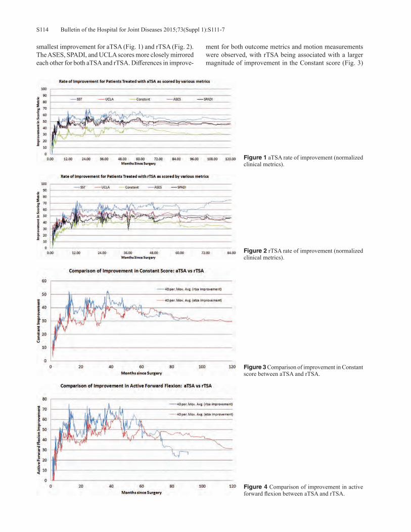
Bulletin of the Hospital for Joint Diseases 2015;73(Suppl 1):S111-7S114
smallest improvement for aTSA (Fig. 1) and rTSA (Fig. 2). The ASES, SPADI, and UCLA scores more closely mirrored each other for both aTSA and rTSA. Differences in improve-
ment for both outcome metrics and motion measurements were observed, with rTSA being associated with a larger magnitude of improvement in the Constant score (Fig. 3)
Figure 1 aTSA rate of improvement (normalized clinical metrics).
Figure 2 rTSA rate of improvement (normalized clinical metrics).
Figure 3 Comparison of improvement in Constant score between aTSA and rTSA.
Figure 4 Comparison of improvement in active forward flexion between aTSA and rTSA.

S115Bulletin of the Hospital for Joint Diseases 2015;73(Suppl 1):S111-7
and active forward flexion (Fig. 4) and aTSA being associ-ated with a larger magnitude of improvement in external rotation (Fig. 5). Regarding the rate of improvement, full improvement was reached between 12 and 24 months for both aTSA and rTSA patients, with the majority of improve-ment noted in the first 6 months (Fig. 6). Finally, during the first 12 months, the rate of improvement associated with rTSA patients was generally 30% larger than that of aTSA patients as described by the slope of the best fit linear trendlines depicted in Figure 6.
Discussion The results of this large-scale database analysis demonstrate the reliability of improvements in outcomes and motion achieved with aTSA and rTSA for various indications. Less
than 5% of patients reported worsening in each of the five clinical metrics after 6 months postoperative follow-up time. Full improvement was noted by 24 months with the majority of the improvement noted in the first 6 months. Utilizing this information, surgeons can counsel their aTSA and rTSA patients that while the majority of clinical improvement will be experienced in the first 6 months, they may continue to make gains for the first 2 years after surgery. Furthermore, rTSA patients can be expected to make gains at a rate 30% faster than their aTSA counterparts, which may be explained by rTSA patient’s demonstrating more profound limitations and symptoms preoperatively. Although the percentage of patients without improve-ment in range of motion was relatively low (< 8%) after 6 months of follow-up in the aTSA group, the rTSA group had
Figure 5 Comparison of improvement in active external rotation between aTSA and rTSA .
Figure 6 The majority of improvement for all metrics occurred in the first 6 months for aTSA (A) and rTSA (B) although full improvement occurred between 12 and 24 months.B
A

Bulletin of the Hospital for Joint Diseases 2015;73(Suppl 1):S111-7S116
a higher percentage of patients without improvement. This was true for abduction and flexion (< 10%) as well as active (< 20%) and passive (< 30%) external rotation. Based on these findings, range of motion appears less predictable after rTSA compared to aTSA. Patients should be made aware of this when considering their surgical options. There is a relatively high percentage of rTSA patients without improvements at all time points pertaining to ac-tive and passive external rotation. Since the percentage of improvement for passive external rotation after rTSA stays relatively constant, the procedure appears to be limiting external rotation due to the biomechanics of the rTSA rather than stiffness. Active external rotation gains may be more limited because passive external rotation is limited, not allowing excursion even with sufficient muscle activation. Alternatively, following rTSA the posterior rotator cuff may not be capable of affecting an ideal moment arm due to a change in tension and line of action.11,12 All reverse prosthe-ses effectively shorten the resting length of the infraspinatus and teres minor, which contributes to the force generated by a muscle. This may have an impact on the degree of external rotation recovered after rTSA and explain why improvement in active external rotation was more prevalent after aTSA as compared to rTSA. Despite a steady decline in the percentage of patients without improvement for active flexion and abduction through 48 months after both aTSA and rTSA, both groups then noted a steady rise in the number of patients without improvement from 48 months and beyond. Beyond 60 months, the percentage of patients without improvement for rTSA was twice the rate than that for aTSA. This reflects a significant loss of overhead function because each successive data point in the study was compared to the preoperative state. Perhaps these declining results reflect the general de-terioration in function occurring with age, particularly given that the average age of rTSA patients was 7 years older (72 vs. 65 years) than that of aTSA patients in this study. Other possible explanations for this finding in the rTSA group are deltoid fatigue and secondary rotator dysfunction.13 These findings demonstrate the importance of longer follow-up beyond 5 years. Since the five clinical scoring metrics were normalized on a 100 point scale, it was possible to make comparisons between metrics. In both prosthesis types, the SST demon-strated the greatest improvement, while the Constant score demonstrated the smallest improvement. It is likely that this difference in magnitude with the Constant score is due to its 25% weight of strength in the calculation, which is often difficult to achieve for this elderly patient population. None of the other five scores emphasizes strength so significantly in the overall calculation of score. Such intrinsic differences in the calculations of each metric score highlight the dif-ficulty in comparing studies that employ different metrics. Conflating two studies that use different metrics may lead to improper conclusions. Conversely, the SPADI, UCLA, and ASES metrics more closely mirrored each other, so studies
employing these metrics may be more comparable. One limitation of this study is the number of data points acquired at the later time points. A majority of the 4,439 follow-up data points were recorded prior to 5 years of follow-up with the minority obtained after 5 years as dem-onstrated in Table 5. Determining trends after 5 years of follow-up is more difficult because of this limitation in data points. Further follow-up time is required to confirm these results and trends. This study is significant because it quantifies and com-pares how patient outcomes improve with time following treatment with both aTSA and rTSA. These results are use-ful to orthopaedic surgeons and clinical researchers since they can be used to establish realistic patient expectations regarding the typical follow-up time required for pain to be reduced and function restored following surgical treatment.
ConclusionOutcomes after aTSA and rTSA using a platform system reliably improve with the majority of subjective and objec-tive improvement occurring in the first 6 months following surgery. Despite common scoring metrics maintaining im-provement over time, range of motion after aTSA and rTSA appears to decrease in a percentage of patients between the fourth and fifth postoperative year. Following rTSA, both passive and active external rotations demonstrate negative improvement or clinical worsening at a high rate persistently during the immediate postoperative period and continuously through a long follow-up period. This limitation is not seen after aTSA where both passive and active external rotation are rapidly achieved in the first 6 months and maintained through long-term follow-up. An improved understanding of the rate of improvement after total shoulder arthroplasty is important to help counsel patients. The setting of more realistic patient expectations preoperatively can lead to greater patient satisfaction postoperatively.
Disclosure Statement Ryan Simovitch, M.D., Yann Marczuk, M.D., and Richard Friedman, M.D., F.R.C.S.C., are consultants for Exactech, Inc. Pierre-Henri Flurin, M.D., Thomas W. Wright, M.D., and Joseph D. Zuckerman, M.D., are consultants for Ex-actech, Inc and receive royalties on products related to this article. Christopher P. Roche, M.S., M.B.A., is an employee of Exactech, Inc., Gainesville, Florida.
References1. Kim SH, Wise BL, Zhang Y, Szabo RM. Increasing incidence
of shoulder arthroplasty in the United States. J Bone Joint Surg Am. 2011 Dec 21;93(24):2249-54.
2. Torchia ME, Cofield RH, Settergren CR. Total shoulder arthroplasty with the Neer prosthesis: long-term results. J Shoulder Elbow Surg. 1997 Nov-Dec;6(6):495-505.
3. Wall B, Nove-Josserand L, O’Connor DP, et al. Reverse total shoulder arthroplasty: a review of results according to etiol-ogy. J Bone Joint Surg Am. 2007 Jul;89(7):1476-85.
4. Mulieri P, Dunning P, Klein S, et al. Reverse shoulder ar-

S117Bulletin of the Hospital for Joint Diseases 2015;73(Suppl 1):S111-7
throplasty for the treatment of irreparable rotator cuff tear without glenohumeral arthritis. J Bone Joint Surg Am. 2010 Nov 3;92(15):2544-56.
5. Frankle M, Siegal S, Pupello D, et al. The Reverse Shoulder Prosthesis for glenohumeral arthritis associated with severe rotator cuff deficiency. A minimum two-year follow-up study of sixty patients. J Bone Joint Surg Am. 2005 Aug;87(8):1697-705.
6. Flurin PH, Marczuk Y, Janout M, et al. Comparison of out-comes using anatomic and reverse total shoulder arthroplasty. Bull Hosp Jt Dis (2013). 2013;71 Suppl 2:101-7.
7. Norris TR, Iannotti JP. Functional outcome after shoulder arthroplasty for primary osteoarthritis: a multicenter study. J Shoulder Elbow Surg. 2002 Mar-Apr;11(2):130-5.
8. Singh JA, Sperling JW, Cofield RH. Revision surgery follow-ing total shoulder arthroplasty: analysis of 2588 shoulders over three decades (1976 to 2008). J Bone Joint Surg Br. 2011 Nov;93(11):1513-7.
9. Guery J, Favard L, Sirveaux F, et al. Reverse total shoulder
arthroplasty. Survivorship analysis of eighty replacements followed for five to ten years. J Bone Joint Surg Am. 2006 Aug;88(8):1742-7.
10. Fox TJ, Foruria AM, Klika BJ, et al. Radiographic survival in total shoulder arthroplasty. J Shoulder Elbow Surg. 2013 Sep;22(9):1221-7.
11. Roche CP, Diep P, Hamilton M, et al. Impact of inferior glenoid tilt, humeral retroversion, bone grafting, and de-sign parameters on muscle length and deltoid wrapping in reverse shoulder arthroplasty. Bull Hosp Jt Dis (2013). 2013;71(4):284-93.
12. Hamilton MA, Diep P, Roche C, et al. Effect of reverse shoul-der design philosophy on muscle moment arms. J Orthop Res. 2015 Apr;33(4):605-13.
13. Young AA, Walch G, Pape G, et al. Secondary rotator cuff dysfunction following total shoulder arthroplasty for primary glenohumeral osteoarthritis: results of a multicenter study with more than five years of follow-up. J Bone Joint Surg Am. 2012 Apr 18;94(8):685-93.

Bulletin of the Hospital for Joint Diseases 2015;73(Suppl 1):S118-23S118
Flurin P-H, Roche CP, Wright TW, Marczuk Y, Zuckerman JD. A comparison and correlation of clinical outcome metrics in anatomic and reverse total shoulder arthroplasty. Bull Hosp Jt Dis. 2015;73(Suppl 1):S118-23.
Abstract
Introduction: Indications for anatomic (aTSA) and re-verse (rTSA) total shoulder arthroplasty are well defined and dependent on the function of the rotator cuff; however, indications for rTSA have gradually extended to complex fractures, revisions, and primary arthritis in very elderly patients. The risk of secondary rupture of a weakened or degenerative rotator cuff is difficult to assess and can lead the orthopaedic surgeon to hesitate between aTSA or rTSA. It, therefore, seems appropriate to compare these two types of prostheses in terms of pain, functional, clinical outcome metric scores, and complications, despite suspected differ-ences between populations and the respective diseases. Methodology: 1,145 patients (69.2 ± 8.9 years) were treated by 12 orthopaedic surgeons in France and in the USA, using either aTSA or rTSA with one platform shoulder system. Five hundred twenty-eight patients received aTSA (66.2 ± 9.0 years; 283 female, 245 male) for treatment of degenerative arthritis, and 617 patients received rTSA (71.8 ± 8.0 years; 392 female, 225 male) for treatment of cuff tear arthroplasty, rotator cuff tear, and osteoarthritis. Each patient was scored preoperatively and at latest follow-up using the SST, UCLA, ASES, Constant, and SPADI metrics; active range of motion was also measured. The average follow-up for all patients was 39.7 ± 18.7 months (aTSA: 42.7 ± 21.9 months; rTSA: 37.1 ± 15.1 months). Improvements in outcome using each metric score were normalized on a 100 point scale, correlated, and
compared. A Student’s two-tailed, unpaired t-test was used to identify differences in preoperative, postoperative, and pre-to-postoperative improvements, where p < 0.05 denoted a significant difference. Results: Preoperatively, rTSA patients had significantly lower mean outcome scores and significantly lower mean active range of motion as compared to aTSA patients. Post-operatively, rTSA and aTSA patients showed no significant difference in active forward flexion or in mean outcome scores as measured by four of the five metrics. rTSA patients had significantly lower active abduction, internal rota-tion, and active and passive external rotation than aTSA patients. However, they had significantly better strength (9.7 vs. 7.3 lbs, p < 0.0001). Preoperative to postoperative mean improvements were compared between both cohorts. rTSA patients were associated with significantly larger improvements in outcomes and also had significantly better improvements in active forward flexion and strength. Con-versely, aTSA patients had significantly better improvement in active and passive external rotation and active internal rotation. Analysis of complications demonstrated a very similar rate between cohorts, with aTSA patients associated with a slightly lower rate (6.6 vs. 7.3%). Conclusion: This retrospective analysis of prospectively acquired data from 1,145 patients who received either a primary aTSA or rTSA prosthesis demonstrates that each device provides significant improvements with very similar mean results. In fact, the mean clinical outcomes associated with the reverse shoulder prostheses approach that of the “gold standard” anatomic device for their respective indi-cations. Furthermore, the complication rates in this series are very similar and also favorable relative to the clinical literature. Findings, such as these, may at some point ex-tend the indications of the reverse prosthesis to patients for whom an anatomical prosthesis could lead to a premature deterioration of the result.
A Comparison and Correlation of Clinical Outcome Metrics in Anatomic and Reverse Total Shoulder Arthroplasty
Pierre-Henri Flurin, M.D., Christopher P. Roche, M.S., M.B.A., Thomas W. Wright, M.D., Yann Marczuk, M.D., and Joseph D. Zuckerman, M.D.
Pierre-Henri Flurin, M.D., Bordeaux-Merignac Clinique du Sport, Merignac, France. Christopher P. Roche, M.S., M.B.A., Exactech, Inc., Gainesville, Florida. Thomas W. Wright, M.D., Department of Orthopaedics and Rehabilitation, University of Florida, Gaines-ville, Florida. Yann Marczuk, M.D., Chenieux Clinic, Limoges, France. Joseph D. Zuckerman, M.D., Department of Orthopaedic Surgery, Hospital for Joint Diseases, NYU Langone Medical Center, New York, New York. Correspondence: Pierre-Henri Flurin, M.D., [email protected].

S119Bulletin of the Hospital for Joint Diseases 2015;73(Suppl 1):S118-23
Conventionally, indications for anatomic (aTSA) and reverse (rTSA) total shoulder arthroplasty are well defined and dependent on the function of the rotator
cuff. The reverse prosthesis was initially defined as a salvage procedure where the use of an anatomic prosthesis was im-possible. Indeed, the high complication rates reported in the literature and the lack of data on longevity did not encourage the preferential use of this type of prosthesis. Despite this, indications for rTSA have gradually extended to complex fractures, revisions, and more recently to primary arthritis in very elderly patients.1-3 The latter indication is based on the risk of secondary rupture of a weakened or degenerative rotator cuff that may compromise medium-term results of aTSA. This risk is difficult to assess and can lead the ortho-paedic surgeon to hesitate between use of aTSA or rTSA in a number of patients. It, therefore, seems appropriate to compare these two types of prostheses in terms of pain, functional, clinical outcome metric scores, and complica-tions, despite suspected differences between populations and the respective diseases. To this end, we retrospectively reviewed prospectively acquired data in a multi-institutional IRB approved database to compare preoperative, postopera-tive, and pre-to-postoperative improvements associated with 1,145 patients who received either aTSA or rTSA in France and in the USA. Outcomes for each prosthesis cohort were scored using five different scoring metrics; each metric was
normalized and correlated to facilitate a comparison of scor-ing systems for each treatment type.
MethodologyA total of 1,145 patients (69.2 ± 8.9 years) were treated by 12 orthopaedic surgeons using either aTSA or rTSA with one platform shoulder system (Equinoxe®, Exactech, Inc.), (Fig. 1). The inclusion criteria were primary total shoulder arthroplasty and a minimum 2-year follow-up where revi-sion surgery was excluded from this series. Five hundred twenty-eight patients (46%) received primary aTSA for treatment of degenerative arthritis. The mean age was 66.2 ± 9.0 years, with 54% females (N = 283) and 46% (N = 245) males. Six hundred seventeen patients (54%) received primary rTSA for treatment of Cuff Tear Arthropathy (CTA), Rotator Cuff Tear (RCT), and Osteoarthritis (OA). The mean age was 71.8 ± 8.0 years with 64% females (N = 392) and 36% males (N = 225). Each patient was scored preoperatively and at latest follow-up using the SST, UCLA, ASES, Constant, and SPADI metrics. Additionally, active abduction, forward flexion, and active and passive external rotation with the arm at the side were measured. Internal rotation was also measured by vertebral segments and was scored by the fol-lowing discrete assignment: 0° = 0, hip = 1, buttocks = 2, sacrum = 3, L5-L4 = 4, L3-L1 = 5, T12-T8 = 6, and T7 or
Figure 1 Equinoxe® Platform Shoulder System (Exactech, Inc., Gainesville, FL).
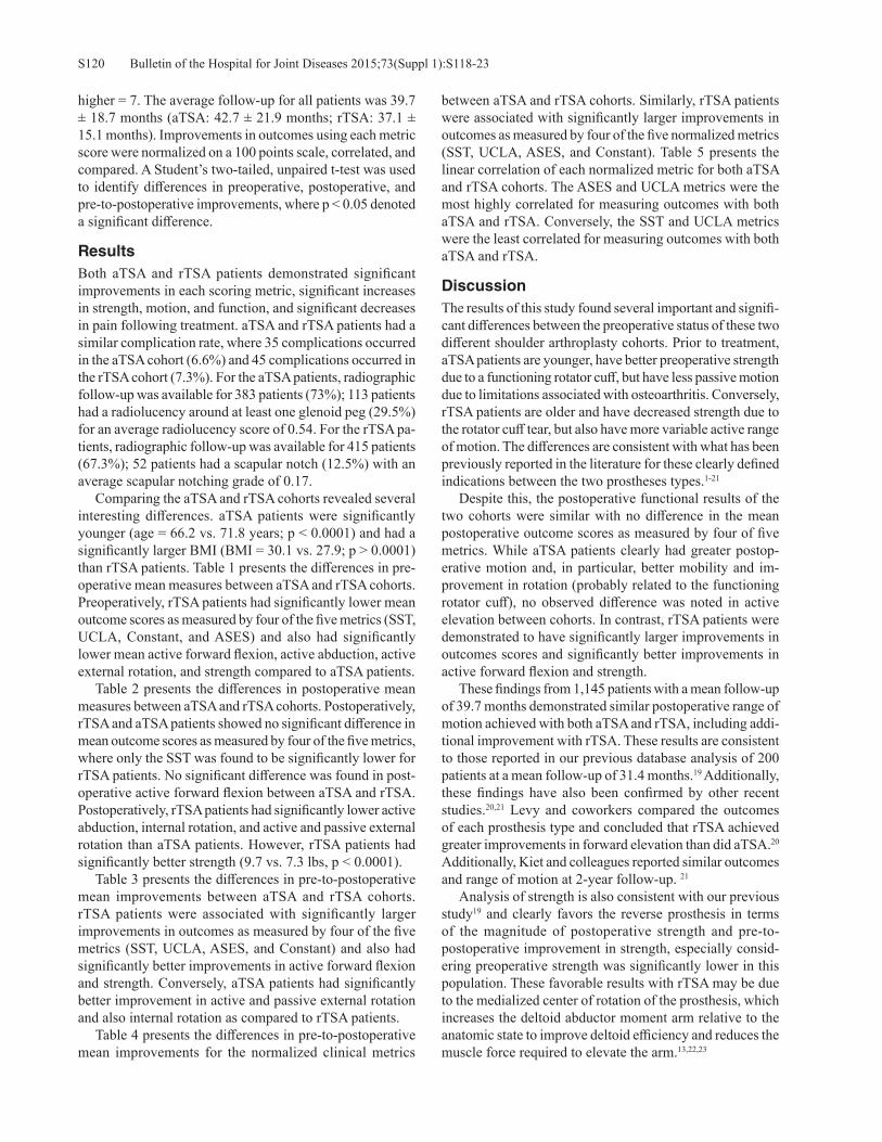
Bulletin of the Hospital for Joint Diseases 2015;73(Suppl 1):S118-23S120
higher = 7. The average follow-up for all patients was 39.7 ± 18.7 months (aTSA: 42.7 ± 21.9 months; rTSA: 37.1 ± 15.1 months). Improvements in outcomes using each metric score were normalized on a 100 points scale, correlated, and compared. A Student’s two-tailed, unpaired t-test was used to identify differences in preoperative, postoperative, and pre-to-postoperative improvements, where p < 0.05 denoted a significant difference.
Results Both aTSA and rTSA patients demonstrated significant improvements in each scoring metric, significant increases in strength, motion, and function, and significant decreases in pain following treatment. aTSA and rTSA patients had a similar complication rate, where 35 complications occurred in the aTSA cohort (6.6%) and 45 complications occurred in the rTSA cohort (7.3%). For the aTSA patients, radiographic follow-up was available for 383 patients (73%); 113 patients had a radiolucency around at least one glenoid peg (29.5%) for an average radiolucency score of 0.54. For the rTSA pa-tients, radiographic follow-up was available for 415 patients (67.3%); 52 patients had a scapular notch (12.5%) with an average scapular notching grade of 0.17. Comparing the aTSA and rTSA cohorts revealed several interesting differences. aTSA patients were significantly younger (age = 66.2 vs. 71.8 years; p < 0.0001) and had a significantly larger BMI (BMI = 30.1 vs. 27.9; p > 0.0001) than rTSA patients. Table 1 presents the differences in pre-operative mean measures between aTSA and rTSA cohorts. Preoperatively, rTSA patients had significantly lower mean outcome scores as measured by four of the five metrics (SST, UCLA, Constant, and ASES) and also had significantly lower mean active forward flexion, active abduction, active external rotation, and strength compared to aTSA patients. Table 2 presents the differences in postoperative mean measures between aTSA and rTSA cohorts. Postoperatively, rTSA and aTSA patients showed no significant difference in mean outcome scores as measured by four of the five metrics, where only the SST was found to be significantly lower for rTSA patients. No significant difference was found in post-operative active forward flexion between aTSA and rTSA. Postoperatively, rTSA patients had significantly lower active abduction, internal rotation, and active and passive external rotation than aTSA patients. However, rTSA patients had significantly better strength (9.7 vs. 7.3 lbs, p < 0.0001). Table 3 presents the differences in pre-to-postoperative mean improvements between aTSA and rTSA cohorts. rTSA patients were associated with significantly larger improvements in outcomes as measured by four of the five metrics (SST, UCLA, ASES, and Constant) and also had significantly better improvements in active forward flexion and strength. Conversely, aTSA patients had significantly better improvement in active and passive external rotation and also internal rotation as compared to rTSA patients. Table 4 presents the differences in pre-to-postoperative mean improvements for the normalized clinical metrics
between aTSA and rTSA cohorts. Similarly, rTSA patients were associated with significantly larger improvements in outcomes as measured by four of the five normalized metrics (SST, UCLA, ASES, and Constant). Table 5 presents the linear correlation of each normalized metric for both aTSA and rTSA cohorts. The ASES and UCLA metrics were the most highly correlated for measuring outcomes with both aTSA and rTSA. Conversely, the SST and UCLA metrics were the least correlated for measuring outcomes with both aTSA and rTSA.
Discussion The results of this study found several important and signifi-cant differences between the preoperative status of these two different shoulder arthroplasty cohorts. Prior to treatment, aTSA patients are younger, have better preoperative strength due to a functioning rotator cuff, but have less passive motion due to limitations associated with osteoarthritis. Conversely, rTSA patients are older and have decreased strength due to the rotator cuff tear, but also have more variable active range of motion. The differences are consistent with what has been previously reported in the literature for these clearly defined indications between the two prostheses types.1-21
Despite this, the postoperative functional results of the two cohorts were similar with no difference in the mean postoperative outcome scores as measured by four of five metrics. While aTSA patients clearly had greater postop-erative motion and, in particular, better mobility and im-provement in rotation (probably related to the functioning rotator cuff), no observed difference was noted in active elevation between cohorts. In contrast, rTSA patients were demonstrated to have significantly larger improvements in outcomes scores and significantly better improvements in active forward flexion and strength. These findings from 1,145 patients with a mean follow-up of 39.7 months demonstrated similar postoperative range of motion achieved with both aTSA and rTSA, including addi-tional improvement with rTSA. These results are consistent to those reported in our previous database analysis of 200 patients at a mean follow-up of 31.4 months.19 Additionally, these findings have also been confirmed by other recent studies.20,21 Levy and coworkers compared the outcomes of each prosthesis type and concluded that rTSA achieved greater improvements in forward elevation than did aTSA.20 Additionally, Kiet and colleagues reported similar outcomes and range of motion at 2-year follow-up. 21
Analysis of strength is also consistent with our previous study19 and clearly favors the reverse prosthesis in terms of the magnitude of postoperative strength and pre-to-postoperative improvement in strength, especially consid-ering preoperative strength was significantly lower in this population. These favorable results with rTSA may be due to the medialized center of rotation of the prosthesis, which increases the deltoid abductor moment arm relative to the anatomic state to improve deltoid efficiency and reduces the muscle force required to elevate the arm.13,22,23

S121Bulletin of the Hospital for Joint Diseases 2015;73(Suppl 1):S118-23
Tab
le 1
C
ompa
rison
of A
vera
ge P
reop
erat
ive
Mea
sure
men
ts, a
TSA
Ver
sus r
TSA
Pat
ient
s
SST
UC
LA
ASE
SC
onst
ant
SPA
DI
Act
ive
Abd
uctio
n
Act
ive
Forw
ard
Flex
ion
Inte
rnal
R
otat
ion
Scor
e
Act
ive
Ext
erna
l R
otat
ion
Pass
ive
Ext
erna
l R
otat
ion
Max
W
eigh
t (lb
s)Pr
eop
aTSA
Avg
± S
t Dev
3.7
± 2.
714
.3 ±
4.0
37.2
± 1
6.3
36.9
± 1
3.0
82.2
± 2
1.2
80.1
± 2
6.8°
95.4
± 3
0.9°
2.9
± 1.
615
.4 ±
19.
3°23
.0 ±
20.
4°2.
5 ±
4.0
Preo
p rT
SA A
vg ±
St D
ev2.
8 ±
2.6
12.3
± 4
.233
.2 ±
17.
130
.2 ±
14.
882
.6 ±
22.
263
.9 ±
34.
8°82
.3 ±
40.
9°2.
9 ±
1.8
12.6
± 2
1.4°
26.0
± 2
3.1°
1.4
± 3.
4P-
valu
e<
0.00
01<
0.00
010.
0003
< 0.
0001
0.78
30<
0.00
01<
0.00
010.
9054
0.01
910.
0245
< 0.
0001
Tab
le 2
C
ompa
rison
of A
vera
ge P
osto
pera
tive
Mea
sure
men
ts, a
TSA
Ver
sus r
TSA
Pat
ient
s
SST
UC
LA
ASE
SC
onst
ant
SPA
DI
Act
ive
Abd
uctio
n
Act
ive
Forw
ard
Flex
ion
Inte
rnal
R
otat
ion
Scor
e
Act
ive
Ext
erna
l R
otat
ion
Pass
ive
Ext
erna
l R
otat
ion
Max
W
eigh
t (lb
s)Po
stop
aT
SA A
vg ±
St D
ev10
.3 ±
2.5
30.2
± 5
.883
.8 ±
20.
170
.6 ±
15.
319
.1 ±
24.
911
8.8
± 31
.1°
140.
1 ±
33.3
°5.
1 ±
1.4
45.7
± 2
0.6°
54.0
± 2
0.7°
7.3
± 5.
7Po
stop
rT
SA A
vg ±
St D
ev10
.0 ±
2.5
30.3
± 5
.084
.5 ±
17.
071
.4 ±
14.
920
.9 ±
24.
110
5.1
± 25
.7°
139.
2 ±
28.1
°4.
6 ±
1.6
32.6
± 1
5.1°
46.0
± 1
5.3°
9.7
± 8.
1P-
valu
e0.
0301
0.85
470.
4988
0.39
580.
2346
< 0.
0001
0.63
09<
0.00
01<
0.00
01<
0.00
01<
0.00
01
Tab
le 3
C
ompa
rison
of A
vera
ge Im
prov
emen
t, aT
SA V
ersu
s rTS
A P
atie
nts
SST
UC
LA
ASE
SC
onst
ant
SPA
DI
Act
ive
Abd
uctio
n
Act
ive
Forw
ard
Flex
ion
Inte
rnal
R
otat
ion
Scor
e
Act
ive
Ext
erna
l R
otat
ion
Pass
ive
Ext
erna
l R
otat
ion
Max
W
eigh
t (lb
s)aT
SA A
vg ±
St D
ev6.
8 ±
3.1
16.6
± 6
.347
.9 ±
22.
735
.5 ±
17.
164
.9 ±
28.
239
.0 ±
37.
0°44
.2 ±
38.
9°2.
2 ±
2.0
30.5
± 2
3.4°
30.9
± 2
2.8°
4.8
± 5.
6rT
SA A
vg ±
St D
ev7.
3 ±
3.2
18.1
± 6
.251
.5 ±
21.
741
.8 ±
20.
261
.4 ±
26.
841
.4 ±
36.
5°56
.6 ±
45.
9°1.
6 ±
2.0
20.0
± 2
3.3°
19.5
± 2
3.7°
8.6
± 7.
8P-
valu
e0.
0201
0.00
060.
0121
< 0.
0001
0.08
020.
2831
< 0.
0001
< 0.
0001
< 0.
0001
< 0.
0001
< 0.
0001

Bulletin of the Hospital for Joint Diseases 2015;73(Suppl 1):S118-23S122
Analysis of complications demonstrated a very similar rate between cohorts, with aTSA patients associated with a slightly lower rate (6.6% vs. 7.3%). The relatively low rate of complications for the reverse prosthesis reported in this large database analysis may be partially explained by the exclusion of surgical revisions but is also likely related to the use of a medial glenoid/lateral humerus prosthesis design that is optimized to minimize scapular notching and maxi-mize range of motion and stability.22-24 Most remarkable, only six dislocations were reported with this rTSA cohort for an instability rate of 0.97%. The 12.5% rate of scapular notching was also low relative to rates reported with other reverse shoulder prostheses13-16; however, this reported in-cidence is consistent with the results of other radiographic analysis using this same prosthesis.25-28 Regarding the analysis of different outcome metrics, the observed differences between metrics reflects the different scoring weights utilized for each metric for pain, function, and strength, and may also imply that each scoring metric has different sensitivities for what defines a “worse” patient and what defines a “good” outcome. Given that there is no stan-dardized scoring system to quantify outcomes with shoulder arthroplasty, the results of this outcome study are significant because they provide the orthopaedic surgeon and clinical researcher with an improved understanding of how five of the most commonly utilized scoring systems relate to one another for both aTSA and rTSA. This study also demonstrated that the ASES and UCLA metrics were the most highly correlated, and the SST and UCLA metrics were the least correlated for both aTSA and rTSA. Future work should attempt to better understand these differences, identify sensitivities, and attempt to create a standardized scoring metric to quantify outcomes with total shoulder arthroplasty. This study has several limitations. It reports on the short- to mid-term clinical results of a single platform shoulder system for 1,145 patients with 2-years minimum follow-up. These comparative results may change with time; the long-
term life of the reverse shoulder prosthesis in particular is unknown. Thus, longer-term follow-up for both aTSA and rTSA is necessary to confirm these results. It should also be noted that database analyses, such as this, contain numerous variables (different patient populations, different surgeons, different surgery centers, different rehabilitation methods, different data collection methods, etc.) that limit their impact. We have done our best to standardize the practices of each data collection site and facilitated the use of standardized data collection forms to quantify outcomes using multiple different scoring metrics. The use of multiple different scor-ing metrics in particular acts to unify the methodology and also diversify any inherent bias between collection sites. Furthermore, we also regularly audit the data to confirm the quality and completeness of the inputs. Another limita-tion is that all radiographic analyses were performed by the operating surgeon on their own patients, and complete radiographic follow-up was available in less than 80% of patients; future work should increase the percentage of radiographic follow-up and also incorporate the use of a single or multiple independent reviewers of all radiographs to further minimize bias.
ConclusionThis retrospective analysis of prospectively acquired data from 1,145 patients who received either a primary aTSA or rTSA Equinoxe® prosthesis demonstrates that each device provides significant improvements with very similar mean results. In fact, the mean clinical outcomes associated with the reverse shoulder prostheses approach that of the “gold standard” anatomic device for their respective indications. Furthermore, the complication rates of these prostheses are very similar and also favorable relative to the clinical litera-ture. Findings, such as these, may at some point extend the indications of the reverse prosthesis to patients for whom an anatomical prosthesis could lead to a premature deterioration of the result. Longer-term clinical follow-up continues to
Table 4 Comparison of Average Improvement (Normalized Scores): aTSA Versus rTSA PatientsNormalized Scores (Improvement = Post-Pre) ASES Constant SPADI SST UCLAaTSA 47.9 ± 22.7 35.5 ± 17.1 49.9 ± 22.7 56.4 ± 26.2 47.4 ± 18.1rTSA 51.5 ± 21.7 41.8 ± 20.2 47.2 ± 20.9 60.6 ± 27.0 51.6 ± 17.7P-value 0.0121 < 0.0001 0.0758 0.0197 0.0007
Table 5 Correlation of Improvement in Outcomes Using Five Clinical Metrics: (aTSA/rTSA)Correlation (aTSA/rTSA) ASES Constant SPADI SST
ASES 1.000
Constant 0.788/0.793 1.000
SPADI 0.850/0.800 0.711/0.741 1.000
SST 0.727/0.758 0.694/0.762 0.803/0.801 1.000UCLA 0.852/0.841 0.789/0.827 0.769/0.690 0.634/0.673

S123Bulletin of the Hospital for Joint Diseases 2015;73(Suppl 1):S118-23
be necessary to confirm these favorable findings using this platform shoulder system.
Disclosure Statement Pierre-Henri Flurin, M.D., Thomas W. Wright, M.D., and
Joseph D. Zuckerman, M.D., are consultants for Exactech, Inc., and receive royalties on products related to this article. Yann Marczuk, M.D., is a consultant for Exactech, Inc. Christopher P. Roche, M.S., M.B.A., is an employee of Exactech, Inc., Gainesville, Florida.
References1. Smith CD, Guyver P, Bunker TD. Indications for reverse
shoulder replacement, a systematic review. J Bone Joint Surg Br. 2012 May;94(5):577-83.
2. Wall B, Nové-Josserand L, O’Connor DP, et al. Reverse Total Shoulder Arthroplasty: A review of Results According to Etiology. J Bone Joint Surg Am. 2007 Jul;89(7):1476-85.
3. Simone JP, Streubel PH, Sperling JW, et al. Anatomical total shoulder replacement with rotator cuff repair for osteoarthris-tis of the shoulder. Bone Joint J. 2014 Feb;96-B(2):224-8.
4. Edwards TB, Kadakia NR, Boulahia A, et al. A comparison of Hemiarthroplasty and total shoulder arthroplasty in the treatment of primary glenohumeral osteoarthritis, Results of a multicenter study. J Shoulder Elbow Surg. 2003 May-Jun;12(3):207-13.
5. Orfaly RM, Rockwood CA Jr, Esenyel CZ, Wirth MA. A prospective functional outcome study of shoulder arthroplasty for osteoarthritis with an intact rotator cuff. J Shoulder Elbow Surg. 2003 May-Jun;12(3):214-21.
6. Godeneche A, Boileau P, Favard L, et al. Prosthetic replace-ment in the treatment of osteoarthritis of the shoulder: Early results of 268 cases. J Shoulder Elbow Surg. 2002 Jan-Feb;11(1):11-8.
7. Gartsman GM, Roddey TS, Hammerman SM. Shoulder Arthroplasty with or without Resurfacing of the Glenoid in Patients Who Have Osteoarthritis. J Bone Joint Surg. 2000 Jan;82(1):26-34.
8. Raiss P, Schmitt M, Bruckner T, et al. Results of Cemented Total Shoulder Replacement with a Minimum Follow-up of Ten Years. J Bone Joint Surg Am. 2012 Dec 5:94(23):e1711-10.
9. Walch G, Young AA, Melis B, et al. Results of a convex-back cemented keeled glenoid component in primary osteoarthritis: multicenter study with a follow-up greater than 5 years. J Shoulder Elbow Surg. 2011 Apr;20(3):385-94.
10. Sirveaux F, Favard L, Oudet D, et al. Grammont inverted total shoulder arthroplasty in the treatment of glenohumeral osteoarthritis with massive rupture of the cuff. J Bone Joint Surg Br. 2004 Apr;86(3):388-95.
11. Werner C, Steinmann PA, Gilbart M, Gerber C. Treatment of painful pseudoparaesis due to irreparable rotator cuff dysfunc-tion with the Delta III reverse ball and socket total shoulder prosthesis. J Bone Joint Surg Am. 2005 Jul;87(7):1476-86.
12. Frankle M, Siegal S, Pupello D, et al. The reverse shoulder prosthesis for glenohumeral arthritis associated with severe rotator cuff deficiency. A minimum two-year follow-up study of sixty patients. J Bone Joint Surg Am. 2005 Aug;87(8):1697-705.
13. Boileau P, Watkinson D, Hatzidakis AM, Hovorka I. The Grammont reverse shoulder prosthesis: results in cuff tear ar-thritis, fracture sequelae, and revision arthroplasty. J Shoulder Elbow Surg. 2006 Sep-Oct;15(5):527-40.
14. Levigne C, Boileau P, Favard L, et al. Scapular notching in reverse shoulder arthroplasty. J Shoulder Elbow Surg. 2008 Nov-Dec;17(6):925-35.
15. Stechel A, Fuhrmann U, Irlenbusch L, et al. Reversed shoulder arthroplasty in cuff tear arthritis, fracture sequelae, and revi-sion arthroplasty. Acta Orthop. 2010 Jun;81(3);367-72.
16. Nolan BM, Ankerson E, Wiater JM. Reverse total shoulder arthroplasty improves function in cuff tear arthropathy. Clin Orthop Relat Res. 2011 Sep;464(9):2476-82.
17. Jiang JJ, Toor AS, Shi LL, Koh JL. Analysis of perioperative complications in patients after total shoulder arthroplasty and reverse total shoulder arthroplasty. J Shoulder Elbow Surg. 2014 Dec;23(12):1852-9.
18. Triplet JJ, Everding NG, Levy JC, Moor MA. Functional internal rotation after shoulder arthroplasty: a comparison of anatomic and reverse shoulder arthroplasty. J Shoulder Elbow Surg. 2015 Jun;24(6):867-74.
19. Flurin PH, Marczuk Y, Janout M, et al. Comparison of out-comes using anatomic and reverse total shoulder arthroplasty. Bull Hosp Jt Dis (2013). 2013;71 Suppl 2:101-7.
20. Levy JC, Everding NG, Gil CC Jr, et al. Speed of recovery after shoulder arthroplasty: a comparison of reverse and ana-tomic total shoulder arthroplasty. 2014 Dec;23(12):1872-81.
21. Kiet TK, Feeley BT, Naimark M, et al. Outcomes after shoul-der replacement: comparison between reverse and anatomic total shoulder arthroplasty. J Shoulder Elbow Surg. 2015 Feb;24(2):179-85.
22. Roche C, Crosby L. Kinematics and biomechanics of reverse total shoulder arthroplasty. In: Nicholson GP (ed): Orthopae-dic Knowledge Update: Shoulder and Elbow. Rosemont, IL: American Academy of Orthopaedic Surgeons, 2013, pp. 45-54
23. Hamilton MA, Diep P, Roche C, et al. Effect of reverse shoul-der design philosophy on muscle moment arms. J Orthop Res. 2015 Apr;33(4):605-13.
24. Roche CP, Diep P, Hamilton M, et al. Impact of inferior glenoid tilt, humeral retroversion, bone grafting, and de-sign parameters on muscle length and deltoid wrapping in reverse shoulder arthroplasty. Bull Hosp Jt Dis (2013). 2013;71(4):284-93.
25. Roche CP, Marczuk Y, Wright TW, et al. Scapular notching and osteophyte formation after reverse shoulder replacement: Radiological analysis of implant position in male and female patients. Bone Joint J. 2013 Apr;95-B(4):530-5.
26. Roche CP, Marczuk Y, Wright TW, et al. Scapular notching in reverse shoulder arthroplasty: validation of a computer impingement model. Bull Hosp Jt Dis (2013). 2013;71(4):278-83.
27. King JJ, Farmer KW, Struk AM, Wright TW. Uncemented versus cemented humeral stem fixation in reverse shoulder arthroplasty. Int Orthop. 2015 Feb;39(2):291-8.
28. Simovitch RW, Gerard BK, Brees JA, et al. Outcomes of reverse total shoulder arthroplasty in a senior athletic population. J Shoulder Elbow Surg. 2015 May 7. pii: S1058-2746(15)00135-4.

Bulletin of the Hospital for Joint Diseases 2015;73(Suppl 1):S124-8S124
Wright TW, Roche CP, Wright L, Flurin P-H, Crosby LA, Zuckerman JD. Reverse shoulder arthroplasty augments for glenoid wear: comparison of pos-terior augments to superior augments. Bull Hosp Jt Dis. 2015;73(Suppl 1):S124-8.
Abstract
Introduction: Patients who are candidates for a reverse total shoulder arthroplasty (rTSA) may have varying amounts and patterns of glenoid wear. The usual treatment of these deformities has been eccentric reaming or bone grafting. Eccentric reaming often removes a large amount of subchondral bone. Bone grafting is technically more dif-ficult and introduces another mode of failure if the graft does not heal. The purpose of this study is to evaluate patients undergoing a rTSA with concomitant superior or posterior glenoid wear who were treated with a superior augmented baseplate (SAB) or posterior augmented baseplate (PAB) without eccentric reaming or bone grafting. Materials and Methods: Prospectively obtained data were queried from a multi-institutional IRB-approved database. Preoperative and postoperative data were analyzed from 39 patients who received a primary rTSA with either an 8° PAB or a 10° SAB and a minimum of 2 years follow-up. Twenty-four (10 females and 14 males, aged 72.3 ± 8.2 years) received a primary rTSA shoulder with a PAB. Fifteen patients (4 females and 11 males, aged 71.7 ± 9.2 years) received a primary rTSA shoulder with a SAB. Each patient was scored preoperatively and at latest follow-up using the
SST, UCLA, ASES, Constant, and SPADI metrics. Active abduction, forward flexion, and active and passive external rotation with the arm at the side were also measured. The average follow-up for rTSA patients with a PAB was 25.6 ± 3.1 months, and the average follow-up for rTSA patients with a SAB was 32.5 ± 6.5 months. A Student’s two-tailed, unpaired t-test was used to identify differences in preopera-tive and postoperative results, where p < 0.05 denoted a significant difference. Results: All patients in both groups demonstrated sig-nificant improvements in pain and function following treat-ment with the reverse shoulder arthroplasty. The PAB rTSA cohort had a scapular notching rate of 6.3%, whereas the SAB rTSA cohort had a scapular notching rate of 14.3%. The PAB outperformed the SAB with the ASES, Constant, and active forward elevation measures. Discussion: The PAB group outperformed the SAB group with the ASES and Constant outcome scores and forward flexion. The reason for this is unknown; however, it may be due to the posterior augment baseplate itself tensioning the remaining external rotators better than the superior aug-ment, or it may be that the posterior augment group had a better posterior cuff. Both implant groups had no revisions or dislocations and had a low notching rate. It appears that a SAB for superior glenoid wear and a PAB for posterior gle-noid wear are viable simple solutions in patients undergoing a rTSA, where each preserves glenoid bone and eliminates the need for glenoid bone grafting.
Eccentric glenoid wear presents a difficult surgical element in patients undergoing shoulder arthroplasty. Surgeons have approached this issue from a number
of directions, including eccentric reaming, bone grafting, and the use of reverse total shoulder arthroplasty (rTSA). More recently a simplified approach to this problem has been introduced with the use of rTSA augmented baseplates.
Reverse Shoulder Arthroplasty Augments for Glenoid WearComparison of Posterior Augments to Superior Augments
Thomas W. Wright, M.D., Christopher P. Roche, M.S., M.B.A., Logan Wright, Pierre-Henri Flurin, M.D., Lynn A. Crosby, M.D., and Joseph D. Zuckerman, M.D.
Thomas W. Wright, M.D., Department of Orthopaedics and Rehabilitation, University of Florida, Gainesville, Florida. Lo-gan Wright, Department of Orthopaedic Surgery, University of Florida, Gainesville, Florida. Christopher P. Roche, M.S., M.B.A., Exactech, Inc., Gainesville, Florida. Pierre-Henri Flurin, M.D., Bordeaux-Merignac Clinique du Sport, Merignac, France. Lynn A. Crosby, M.D., Department of Orthopaedic Surgery, Georgia Regents University, Augusta, Georgia. Joseph D. Zuckerman, M.D., Department of Orthopaedic Surgery, Hospital for Joint Diseases, NYU Langone Medical Center, New York, New York. Correspondence: Thomas W. Wright, M.D., Department of Ortho-paedics and Rehabilitation, University of Florida, PO Box 112727, Gainesville, Florida 32611-2727; [email protected].
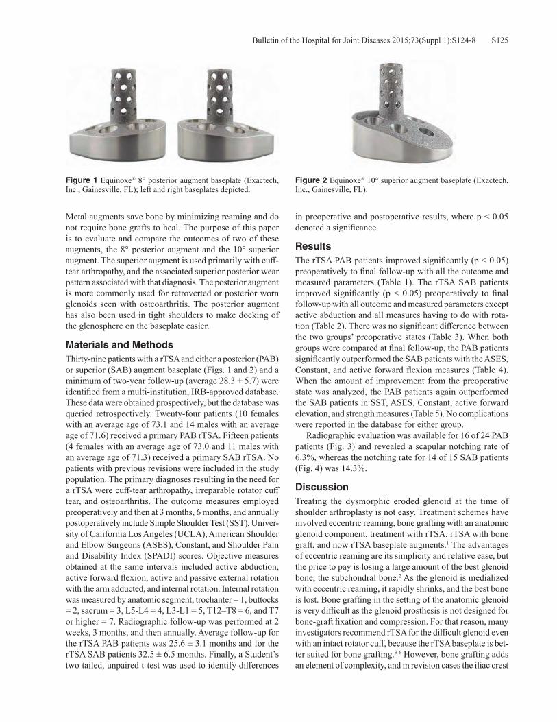
S125Bulletin of the Hospital for Joint Diseases 2015;73(Suppl 1):S124-8
Metal augments save bone by minimizing reaming and do not require bone grafts to heal. The purpose of this paper is to evaluate and compare the outcomes of two of these augments, the 8° posterior augment and the 10° superior augment. The superior augment is used primarily with cuff-tear arthropathy, and the associated superior posterior wear pattern associated with that diagnosis. The posterior augment is more commonly used for retroverted or posterior worn glenoids seen with osteoarthritis. The posterior augment has also been used in tight shoulders to make docking of the glenosphere on the baseplate easier.
Materials and MethodsThirty-nine patients with a rTSA and either a posterior (PAB) or superior (SAB) augment baseplate (Figs. 1 and 2) and a minimum of two-year follow-up (average 28.3 ± 5.7) were identified from a multi-institution, IRB-approved database. These data were obtained prospectively, but the database was queried retrospectively. Twenty-four patients (10 females with an average age of 73.1 and 14 males with an average age of 71.6) received a primary PAB rTSA. Fifteen patients (4 females with an average age of 73.0 and 11 males with an average age of 71.3) received a primary SAB rTSA. No patients with previous revisions were included in the study population. The primary diagnoses resulting in the need for a rTSA were cuff-tear arthropathy, irreparable rotator cuff tear, and osteoarthritis. The outcome measures employed preoperatively and then at 3 months, 6 months, and annually postoperatively include Simple Shoulder Test (SST), Univer-sity of California Los Angeles (UCLA), American Shoulder and Elbow Surgeons (ASES), Constant, and Shoulder Pain and Disability Index (SPADI) scores. Objective measures obtained at the same intervals included active abduction, active forward flexion, active and passive external rotation with the arm adducted, and internal rotation. Internal rotation was measured by anatomic segment, trochanter = 1, buttocks = 2, sacrum = 3, L5-L4 = 4, L3-L1 = 5, T12–T8 = 6, and T7 or higher = 7. Radiographic follow-up was performed at 2 weeks, 3 months, and then annually. Average follow-up for the rTSA PAB patients was 25.6 ± 3.1 months and for the rTSA SAB patients 32.5 ± 6.5 months. Finally, a Student’s two tailed, unpaired t-test was used to identify differences
in preoperative and postoperative results, where p < 0.05 denoted a significance.
ResultsThe rTSA PAB patients improved significantly (p < 0.05) preoperatively to final follow-up with all the outcome and measured parameters (Table 1). The rTSA SAB patients improved significantly (p < 0.05) preoperatively to final follow-up with all outcome and measured parameters except active abduction and all measures having to do with rota-tion (Table 2). There was no significant difference between the two groups’ preoperative states (Table 3). When both groups were compared at final follow-up, the PAB patients significantly outperformed the SAB patients with the ASES, Constant, and active forward flexion measures (Table 4). When the amount of improvement from the preoperative state was analyzed, the PAB patients again outperformed the SAB patients in SST, ASES, Constant, active forward elevation, and strength measures (Table 5). No complications were reported in the database for either group. Radiographic evaluation was available for 16 of 24 PAB patients (Fig. 3) and revealed a scapular notching rate of 6.3%, whereas the notching rate for 14 of 15 SAB patients (Fig. 4) was 14.3%.
DiscussionTreating the dysmorphic eroded glenoid at the time of shoulder arthroplasty is not easy. Treatment schemes have involved eccentric reaming, bone grafting with an anatomic glenoid component, treatment with rTSA, rTSA with bone graft, and now rTSA baseplate augments.1 The advantages of eccentric reaming are its simplicity and relative ease, but the price to pay is losing a large amount of the best glenoid bone, the subchondral bone.2 As the glenoid is medialized with eccentric reaming, it rapidly shrinks, and the best bone is lost. Bone grafting in the setting of the anatomic glenoid is very difficult as the glenoid prosthesis is not designed for bone-graft fixation and compression. For that reason, many investigators recommend rTSA for the difficult glenoid even with an intact rotator cuff, because the rTSA baseplate is bet-ter suited for bone grafting.3-6 However, bone grafting adds an element of complexity, and in revision cases the iliac crest
Figure 1 Equinoxe® 8° posterior augment baseplate (Exactech, Inc., Gainesville, FL); left and right baseplates depicted.
Figure 2 Equinoxe® 10° superior augment baseplate (Exactech, Inc., Gainesville, FL).

Bulletin of the Hospital for Joint Diseases 2015;73(Suppl 1):S124-8S126Ta
ble
1
Aver
age
Preo
pera
tive
and
Post
oper
ativ
e O
utco
me
Scor
es, r
TSA
Pat
ient
s with
PA
Bs
SST
UC
LA
ASE
SC
onst
ant
SPA
DI
Act
ive
Abd
uctio
n
Act
ive
Forw
ard
Flex
ion
Inte
rnal
R
otat
ion
Scor
e
Act
ive
Ext
erna
l R
otat
ion
Pass
ive
Ext
erna
l R
otat
ion
Max
W
eigh
t (lb
s)Pr
eop
Post
Aug
Avg
± S
t Dev
3.5
± 3.
413
.2 ±
4.3
39.9
± 1
9.3
34.3
± 1
3.4
73.2
± 2
0.1
75.8
± 2
8.5°
85.3
± 2
9.8°
2.4
± 1.
412
.0 ±
17.
4°23
.7 ±
19.
5°2.
0 ±
3.2
Post
op P
ost A
ug A
vg ±
St D
ev9.
8 ±
2.0
30.6
± 5
.186
.9 ±
12.
974
.2 ±
13.
620
.2 ±
19.
911
2.6
± 24
.6°
140.
7 ±
24.2
°4.
2 ±
1.8
30.6
± 1
6.0°
45.9
± 1
4.5°
12.0
± 9
.3P-
valu
e <
0.0
001
< 0
.000
10.
0003
< 0
.000
1 <
0.0
001
< 0
.000
1 <
0.0
001
0.00
060.
0006
0.00
01 <
0.0
001
Tab
le 2
Av
erag
e Pr
eope
rativ
e an
d Po
stop
erat
ive
Out
com
e Sc
ores
, rTS
A P
atie
nts w
ith S
AB
s
SST
UC
LA
ASE
SC
onst
ant
SPA
DI
Act
ive
Abd
uctio
n
Act
ive
Forw
ard
Flex
ion
Inte
rnal
R
otat
ion
Scor
e
Act
ive
Ext
erna
l R
otat
ion
Pass
ive
Ext
erna
l R
otat
ion
Max
W
eigh
t (lb
s)Pr
eop
Sup
Aug
Avg
± S
t Dev
4.9
± 3.
314
.2 ±
4.0
40.9
± 1
8.0
34.3
± 1
4.6
78.4
± 2
5.2
76.1
± 3
3.5°
82.5
± 2
9.5°
3.4
± 1.
817
.6 ±
25.
3°33
.2 ±
23.
5°1.
0 ±
2.8
Post
op S
up A
ug A
vg ±
St D
ev8.
6 ±
4.5
27.9
± 7
.773
.4 ±
27.
660
.4 ±
21.
739
.4 ±
39.
395
.0 ±
32.
8°11
0.7
± 34
.6°
4.8
± 2.
131
.1 ±
16.
7°47
.7 ±
18.
9°5.
4 ±
4.6
P-va
lue
0.01
43 <
0.0
001
0.00
070.
0007
0.00
310.
1359
0.02
560.
0684
0.10
420.
0869
0.00
44
Tab
le 3
C
ompa
rison
of A
vera
ge P
reop
erat
ive
Mea
sure
men
ts, r
TSA
Pat
ient
s with
PA
Bs a
nd S
AB
s
SST
UC
LA
ASE
SC
onst
ant
SPA
DI
Act
ive
Abd
uctio
n
Act
ive
Forw
ard
Flex
ion
Inte
rnal
R
otat
ion
Scor
e
Act
ive
Ext
erna
l R
otat
ion
Pass
ive
Ext
erna
l R
otat
ion
Max
W
eigh
t (lb
s)Pr
eop
Post
Aug
Avg
± S
t Dev
3.5
± 3.
413
.2 ±
4.3
39.9
± 1
9.3
34.3
± 1
3.4
73.2
± 2
0.1
75.8
± 2
8.5°
85.3
± 2
9.8°
2.4
± 1.
412
.0 ±
17.
4°23
.7 ±
19.
5°2.
0 ±
3.2
Preo
p Su
p A
ug A
vg ±
St D
ev4.
9 ±
3.3
14.2
± 4
.040
.9 ±
18.
034
.3 ±
14.
678
.4 ±
25.
276
.1 ±
33.
5°82
.5 ±
29.
5°3.
4 ±
1.8
17.6
± 2
5.3°
33.2
± 2
3.5°
1.0
± 2.
8P-
valu
e0.
2340
0.48
940.
8763
0.98
550.
5365
0.97
500.
7761
0.06
520.
4166
0.17
940.
3283
Tab
le 4
C
ompa
rison
of A
vera
ge P
osto
pera
tive
Mea
sure
men
ts, r
TSA
Pat
ient
s with
PA
Bs a
nd S
AB
s
SST
UC
LA
ASE
SC
onst
ant
SPA
DI
Act
ive
Abd
uctio
n
Act
ive
Forw
ard
Flex
ion
Inte
rnal
R
otat
ion
Scor
e
Act
ive
Ext
erna
l R
otat
ion
Pass
ive
Ext
erna
l R
otat
ion
Max
W
eigh
t (lb
s)Po
stop
Pos
t Aug
Avg
± S
t Dev
9.8
± 2.
030
.6 ±
5.1
86.9
± 1
2.9
74.2
± 1
3.6
20.2
± 1
9.9
112.
6 ±
24.6
°14
0.7
± 24
.2°
4.2
± 1.
830
.6 ±
16.
0°45
.9 ±
14.
5°12
.0 ±
9.3
Post
op S
up A
ug A
vg ±
St D
ev8.
6 ±
4.5
27.9
± 7
.773
.4 ±
27.
660
.4 ±
21.
739
.4 ±
39.
395
.0 ±
32.
8°11
0.7
± 34
.6°
4.8
± 2.
131
.1 ±
16.
7°47
.7 ±
18.
9°5.
4 ±
4.6
P-va
lue
0.24
290.
2224
0.04
640.
0260
0.07
230.
0788
0.00
480.
4392
0.92
940.
7579
0.01
91
Tab
le 5
C
ompa
rison
of A
vera
ge Im
prov
emen
t, rT
SA P
atie
nts w
ith P
AB
s and
SA
Bs
SST
UC
LA
ASE
SC
onst
ant
SPA
DI
Act
ive
Abd
uctio
n
Act
ive
Forw
ard
Flex
ion
Inte
rnal
R
otat
ion
Scor
e
Act
ive
Ext
erna
l R
otat
ion
Pass
ive
Ext
erna
l R
otat
ion
Max
W
eigh
t (lb
s)Po
st A
ug A
vg ±
St D
ev6.
3 ±
3.1
16.9
± 5
.846
.9 ±
18.
939
.3 ±
16.
653
.1 ±
17.
536
.2 ±
18.
1°54
.1 ±
25.
8°1.
8 ±
2.0
18.5
± 1
7.8°
21.9
± 1
9.6°
9.9
± 8.
6Su
p A
ug A
vg ±
St D
ev3.
7 ±
3.8
13.2
± 6
.732
.6 ±
21.
725
.7 ±
20.
239
.0 ±
29.
718
.6 ±
35.
2°28
.6 ±
38.
8°1.
3 ±
2.5
13.3
± 2
5.8°
14.4
± 2
1.1°
4.3
± 4.
7P-
valu
e0.
0261
0.10
890.
0353
0.03
720.
0951
0.05
990.
0250
0.52
680.
4813
0.29
820.
0337

S127Bulletin of the Hospital for Joint Diseases 2015;73(Suppl 1):S124-8
Figure 3 A, Grashey view of a shoulder with a PAB. B, axillary lateral view of a shoulder with a PAB.
BA
Figure 4 Grashey view of a shoulder with a SAB.
becomes the autograft site or an allograft must be employed. For the bone-grafted rTSA patient to have a successful result, some or all of the bone graft must incorporate. Therefore, the potential lack of bone-graft incorporation introduces another mode of failure with these difficult shoulders. Metal baseplate augments have the advantage of minimizing an-terior reaming with the posterior worn glenoid and inferior reaming with the superior worn glenoid.7 Subchondral bone preservation allows for better support of the implant and as-sociated screws. With metal augments, the use of bone graft is not necessary, thus, graft incorporation is not an issue. This study evaluated the viability of metal baseplate aug-ments as a simple solution for the eroded glenoid undergoing rTSA. Based on this short-term clinical study of a minimum of 2-year follow-up, both the posterior and superior aug-ments appear to be effective. When comparing the PAB rTSA to the SAB rTSA, the PAB clearly performs better. However, despite their preoperative measures being the same, the PAB is used more for osteoarthritic wear patterns, whereas the SAB is used more for the rotator-cuff arthropathy group. It is likely that the PAB group has a better posterior cuff even though there were no significant differences in strength or rotation observed preoperatively. The SAB group had longer follow-up and a higher percentage of males, which may have had some influence on outcome. Despite these differences, it is possible that the posterior augment itself is superior to the superior augment as it better tensions the remaining posterior rotator cuff and may allow for better clearance between the humeral implant and the native glenoid with external rota-tion. Concerning notching, the PAB group also appeared to

Bulletin of the Hospital for Joint Diseases 2015;73(Suppl 1):S124-8S128
perform better, though the SAB group had longer follow-up. With numbers this small, we cautiously speculate that it is possible that the posterior augment diminishes posterior contact of the humeral component with the glenoid, reducing the occurance of scapular notching.
ConclusionIn conclusion, it has been shown in the short-term that both the PAB an SAB are viable solutions for treatment of the eroded glenoid. The application of the metal augment solution is straight-forward, minimizes the destruction of subchondral glenoid bone, and eliminates the necessity for using bone graft. The complication and notching rates are low. Based on this small short-term outcome comparison study, the PAB appears to outperform the SAB; however, the reason for this may be multifactorial and not solely related to the implant.
Conflict of Interest StatementThomas W. Wright, M.D., Pierre-Henri Flurin, M.D., Joseph D. Zuckerman, M.D., are consultants for Exactech, Inc., and receive royalties on products related to this article. Logan Wright has no conflict of interest to report. Christopher P. Roche, M.S., M.B.A., is an employee of Exactech, Inc., Gainesville, Florida.
References1. Gilot GJ. Addressing glenoid erosion in reverse total shoulder
arthroplasty. Bull Hosp Jt Dis (2013). 2013;71(Suppl 2):S51-3.
2. Kersten AD, Flores-Hernandez C, Hoenecke HR, et al. Poste-rior augmented glenoid designs preserve more bone in bicon-cave glenoids. J Shoulder Elbow Surg. 2015 Jul;24(7):1135-41.
3. Hsu JE, Ricchetti ET, Huffman GR, et al. Addressing glenoid bone deficiency and asymmetric posterior erosion in shoulder arthroplasty. J Shoulder Elbow Surg. 2013 Sep;22(9):1298-308.
4. Denard PJ, Walch G. Current concepts in the surgical man-agement of primary glenohumeral arthritis with a biconcave glenoid. J Shoulder Elbow Surg. 2013 Nov;22(11):1589-98.
5. Werner BS, Böhm D, Abdelkawi A, et al. Glenoid bone grafting in reverse shoulder arthroplasty for long-standing anterior shoulder dislocation. J Shoulder Elbow Surg. 2014 Nov;23(11):1655-61.
6. Hoffelner T, Moroder P, Auffarth A, et al. Outcomes after shoulder arthroplasty revision with glenoid reconstruction and bone grafting. Int Orthop. 2014 Apr;38(4):775-82.
7. Roche CP, Stroud NJ, Martin BL, et al. Achieving fixation in glenoids with superior wear using reverse shoulder arthro-plasty. J Shoulder Elbow Surg. 2013 Dec;22(12):1695-701.
S129Bulletin of the Hospital for Joint Diseases 2015;73(Suppl 1):S129-35
Jones RB, Wright TW, Roche CP. Bone grafting the glenoid versus use of augmented glenoid baseplates with reverse shoulder arthroplasty. Bull Hosp Jt Dis. 2015;73(Suppl 1):S129-35.
Abstract
Background: Large glenoid defects are a difficult recon-structive problem for surgeons performing reverse shoulder arthroplasty (rTSA). Options to address glenoid defects include eccentric reaming, bone grafting, and augmented glenoid baseplates. Augmented glenoid baseplates may provide a simpler, cost-effective, bone-preserving option compared to other techniques. No studies report the use of augmented baseplates to correct glenoid deformity in rTSA relative to the use of glenoid bone graft. Materials and Methods: We retrospectively reviewed 80 patients that received a primary rTSA and received either a structural bone graft or an augmented glenoid baseplate to address a significant glenoid defect. There were 39 patients in the augmented baseplate cohort and 41 patients in the bone graft cohort. The augmented baseplate cohort con-tained 24 8° posterior augment implants and 15 10° superior augment baseplates. The bone graft cohort consisted of 36 autograft humeral heads and 5 allograft femoral heads. The average follow-up for rTSA patients with an augmented baseplate was 28.3 ± 5.7 months, and the average follow-up for rTSA patients with glenoid bone graft was 34.1 ± 15.0 months. Each patient was scored preoperatively and at latest follow-up using the SST, UCLA, ASES, Constant, and SPADI metrics. Range of motion data was obtained as well. Results: All patients demonstrated significant improve-ments in pain, ROM, and functional scores following treatment with rTSA using either augmented baseplates or glenoid bone graft to correct glenoid defects. The database
contained no complications for the augmented glenoid baseplate cohort, and six complications (14.6%) for the glenoid bone graft cohort (including two glenoid loosenings and graft failures). Additionally, the augmented baseplate cohort showed a lower scapular notching rate of 10% as compared to the bone graft cohort which had a notching rate of 18.5%. Discussion: The results of this study suggest that either augmented glenoid baseplates or glenoid bone graft can be used to address large glenoid defects during rTSA with significant improvement in outcomes. Augmented glenoid baseplates may achieve a lower complication and scapu-lar notching rate, but additional and longer-term clinical follow-up is required to confirm these results.
Glenoid deficiency is a common occurrence in pa-tients undergoing shoulder arthroplasty. It has been reported that 39% of patients with rotator cuff tear
arthropathy (CTA) will have acquired glenoid defects.1,2 Adverse consequences can occur from implantation of a reverse total shoulder arthroplasty (rTSA) in patients with severely eroded glenoids. Excessive medialization of the implants can lead to muscle shortening and inferomedial impingement causing scapular notching resulting in bone erosion and polyethylene wear.3-6 Superior tilting of the glenoid baseplate can increase the risk of aseptic loosening, increase shear forces, and decrease the stabilizing compres-sive forces of the reverse shoulder implant.7-10 Furthermore, excessive glenoid wear medializes the humerus, which can decrease deltoid wrapping around the greater tuberosity leading to instability as well as cosmetic issues in some patients5,6 (Fig. 1). Options to address glenoid bone loss with rTSA include eccentric reaming, bone grafting, and the use of augmented glenoid baseplates. Eccentric reaming is non-ideal as it requires removal of additional glenoid bone and further
Bone Grafting the Glenoid Versus Use of Augmented Glenoid Baseplates with Reverse Shoulder Arthroplasty
Richard B. Jones, M.D., Thomas W. Wright, M.D., and Christopher P. Roche, M.S., M.B.A.
Richard B. Jones, M.D., Southeastern Sports Medicine, Asheville, North Carolina. Thomas W. Wright, M.D., Department of Ortho-paedics and Rehabilitation, University of Florida, Gainesville, Florida. Christopher P. Roche, M.S., M.B.A., Exactech, Inc., Gainesville, Florida.Correspondence: Richard B. Jones, M.D., [email protected].

Bulletin of the Hospital for Joint Diseases 2015;73(Suppl 1):S129-35S130
medializes the joint line.11-13 The benefits of augmented baseplates include the ability to correct deformity without eccentric reaming, thereby preserving bone stock and avoid-ing glenoid bone grafting, which adds time and difficulty to the case.10,14 Glenoid bone grafting also produces greater costs and adds another potential site of failure if the graft does not incorporate.15-18 The purpose of this study is to compare the outcomes of rTSA in patients with large glenoid defects corrected using either structural bone graft behind the glenoid baseplate or augmented glenoid baseplates. We hypothesized that both options would achieve improved clinical outcomes, and that there would be no difference in outcomes between the two cohorts.
MethodologyAn international multicenter data registry was utilized. Preoperative and postoperative data was analyzed from 80 patients with glenoid bone loss (average age: 71.6 years) with a minimum of 2-years follow-up (average follow-up: 31.2 months) and underwent primary rTSA using either an augmented glenoid baseplate (cohort composed of 24 pa-tients with a 8° posterior augment baseplate and 15 patients with a 10° superior augment baseplate) or a glenoid bone graft placed behind the baseplate (cohort composed of 5 pa-tients with allograft and 36 patients with autograft) to obtain glenoid fixation in an eroded scapula. All grafts were used to correct glenoid deficiencies, not to lateralize the center of rotation. Thirty-nine patients (14 female, average age: 73.1 years; 25 male, 71.5 years) received the Equinoxe® rTSA shoulder with an augmented baseplate for treatment of CTA, RCT, or OA with a glenoid defect (average age: 72.1 ± 8.5 years). Forty-one patients (27 female, average: 73.0 years; 14 male, average: 66.9 years) received the Equinoxe® rTSA shoulder with glenoid bone graft for treatment of CTA, RCT, and OA with a glenoid defect (average age: 71.2 ± 7.6 years). Each patient was scored preoperatively and at latest follow-up using the SST, UCLA, ASES, Constant, and SPADI metrics; additionally, active abduction, forward flexion, and active and passive external rotation with the arm at the side were measured. Internal rotation was also measured by vertebral segments and was scored by the fol-lowing discrete assignment: 0° = 0, hip = 1, buttocks = 2, sacrum = 3, L5-L4 = 4, L3-L1 = 5, T12-T8 = 6, and T7 or higher = 7. The average follow-up for rTSA patients with an augmented baseplate was 28.3 ± 5.7 months, and the average follow-up for rTSA patients with glenoid bone graft was 34.1 ± 15.0 months. A Student’s two-tailed, unpaired t-test was used to identify differences in preoperative and postoperative results, where p < 0.05 denoted a significant difference.
ResultsAll patients demonstrated significant improvements in pain and function following treatment with rTSA using either augmented glenoid baseplates or glenoid bone graft to
Figure 1 Joint medialization with glenoid wear shortens the rota-tor cuff muscles and reduces deltoid wrapping. When performing rTSA, bone grafting or augmented baseplates are recommended to restore the native joint line to improve rotator cuff muscle tension and deltoid wrapping.

S131Bulletin of the Hospital for Joint Diseases 2015;73(Suppl 1):S129-35
Tab
le 1
Av
erag
e Pr
eope
rativ
e an
d Po
stop
erat
ive
Out
com
e Sc
ores
, rTS
A P
atie
nts w
ith A
ugm
ente
d B
asep
late
s
SST
UC
LA
ASE
SC
onst
ant
SPA
DI
Act
ive
Abd
uctio
n
Act
ive
Forw
ard
Flex
ion
Inte
rnal
R
otat
ion
Scor
e
Act
ive
Ext
erna
l R
otat
ion
Pass
ive
Ext
erna
l R
otat
ion
Max
W
eigh
t (lb
s)Pr
eop
Aug
men
t Avg
± S
t Dev
4.1
± 3.
313
.6 ±
4.2
40.3
± 1
8.6
34.3
± 1
3.7
75.5
± 2
3.8
75.9
± 3
0.1°
84.3
± 2
9.3°
2.8
± 1.
614
.2 ±
20.
6°27
.4 ±
21.
3°1.
6 ±
3.1
Post
op A
ugm
ent A
vg ±
St D
ev9.
4 ±
3.2
29.5
± 6
.381
.7 ±
20.
668
.7 ±
18.
428
.7 ±
31.
110
5.5
± 29
.0°
128.
7 ±
32.0
°4.
4 ±
1.9
30.8
± 1
6.0°
46.6
± 1
6.1°
9.3
± 8.
3P-
valu
e<
0.00
01<
0.00
010.
0003
< 0.
0001
< 0.
0001
< 0.
0001
< 0.
0001
0.00
020.
0003
< 0.
0001
< 0.
0001
Tab
le 2
Av
erag
e Pr
eope
rativ
e an
d Po
stop
erat
ive
Out
com
e Sc
ores
, rTS
A P
atie
nts w
ith G
leno
id B
one
Gra
ft
SST
UC
LA
ASE
SC
onst
ant
SPA
DI
Act
ive
Abd
uctio
n
Act
ive
Forw
ard
Flex
ion
Inte
rnal
R
otat
ion
Scor
e
Act
ive
Ext
erna
l R
otat
ion
Pass
ive
Ext
erna
l R
otat
ion
Max
W
eigh
t (lb
s)Pr
eop
Bon
e G
raft
Avg
± S
t Dev
2.8
± 2.
612
.2 ±
3.1
35.0
± 1
6.4
30.0
± 1
1.8
83.2
± 2
2.3
67.0
± 2
7.8°
78.5
± 2
7.5°
2.5
± 1.
611
.4 ±
22.
0°20
.7 ±
21.
8°1.
7 ±
4.8
Post
op B
one
Gra
ft A
vg ±
St D
ev9.
0 ±
3.4
28.2
± 5
.780
.2 ±
22.
564
.6 ±
17.
228
.4 ±
30.
610
5.1
± 25
.4°
124.
7 ±
23.9
°4.
3 ±
1.6
30.5
± 1
7.3°
44.3
± 2
0.8°
6.7
± 7.
6P-
valu
e<
0.00
01<
0.00
01<
0.00
01<
0.00
01<
0.00
01<
0.00
01<
0.00
01<
0.00
010.
0001
< 0.
0001
0.00
11
Tab
le 3
C
ompa
rison
of A
vera
ge P
reop
erat
ive
Mea
sure
men
ts, r
TSA
Pat
ient
s with
Aug
men
t Bas
epla
tes a
nd G
leno
id B
one
Gra
ft
SST
UC
LA
ASE
SC
onst
ant
SPA
DI
Act
ive
Abd
uctio
n
Act
ive
Forw
ard
Flex
ion
Inte
rnal
R
otat
ion
Scor
e
Act
ive
Ext
erna
l R
otat
ion
Pass
ive
Ext
erna
l R
otat
ion
Max
W
eigh
t (lb
s)Pr
eop
Aug
men
t Avg
± S
t Dev
4.1
± 3.
313
.6 ±
4.2
40.3
± 1
8.6
34.3
± 1
3.7
75.5
± 2
3.8
75.9
± 3
0.1°
84.3
± 2
9.3°
2.8
± 1.
614
.2 ±
20.
6°27
.4 ±
21.
3°1.
6 ±
3.1
Preo
p B
one
Gra
ft A
vg ±
St D
ev2.
8 ±
2.6
12.2
± 3
.135
.0 ±
16.
430
.0 ±
11.
883
.2 ±
22.
367
.0 ±
27.
8°78
.5 ±
27.
5°2.
5 ±
1.6
11.4
± 2
2.0°
20.7
± 2
1.8°
1.7
± 4.
8P-
valu
e0.
1088
0.11
710.
1933
0.15
190.
1923
0.17
420.
3688
0.35
340.
5646
0.17
740.
9179
Tab
le 4
C
ompa
rison
of A
vera
ge P
osto
pera
tive
Mea
sure
men
ts, r
TSA
Pat
ient
s with
Aug
men
t Bas
epla
tes a
nd G
leno
id B
one
Gra
ft
SST
UC
LA
ASE
SC
onst
ant
SPA
DI
Act
ive
Abd
uctio
n
Act
ive
Forw
ard
Flex
ion
Inte
rnal
R
otat
ion
Scor
e
Act
ive
Ext
erna
l R
otat
ion
Pass
ive
Ext
erna
l R
otat
ion
Max
W
eigh
t (lb
s)Po
stop
Aug
men
t Avg
± S
t Dev
9.4
± 3.
229
.5 ±
6.3
81.7
± 2
0.6
68.7
± 1
8.4
28.7
± 3
1.1
105.
5 ±
29.0
°12
8.7
± 32
.0°
4.4
± 1.
930
.8 ±
16.
0°46
.6 ±
16.
1°9.
3 ±
8.3
Post
op B
one
Gra
ft A
vg ±
St D
ev9.
0 ±
3.4
28.2
± 5
.780
.2 ±
22.
564
.6 ±
17.
228
.4 ±
30.
610
5.1
± 25
.4°
124.
7 ±
23.9
°4.
3 ±
1.6
30.5
± 1
7.3°
44.3
± 2
0.8°
6.7
± 7.
6P-
valu
e0.
6513
0.35
530.
7647
0.33
110.
9695
0.95
040.
5473
0.69
840.
9455
0.61
100.
1743
Tab
le 5
C
ompa
rison
of A
vera
ge Im
prov
emen
t, rT
SA P
atie
nts w
ith A
ugm
ent B
asep
late
s and
Gle
noid
Bon
e G
raft
SST
UC
LA
ASE
SC
onst
ant
SPA
DI
Act
ive
Abd
uctio
n
Act
ive
Forw
ard
Flex
ion
Inte
rnal
R
otat
ion
Scor
e
Act
ive
Ext
erna
l R
otat
ion
Pass
ive
Ext
erna
l R
otat
ion
Max
W
eigh
t (lb
s)A
ugm
ent A
vg ±
St D
ev5.
3 ±
3.5
15.5
± 6
.341
.4 ±
21.
033
.9 ±
19.
146
.9 ±
24.
329
.2 ±
27.
2°43
.9 ±
33.
6°1.
6 ±
2.2
16.4
± 2
1.2°
19.0
± 2
0.2°
7.7
± 7.
8B
one
Gra
ft A
vg ±
St D
ev6.
2 ±
3.8
16.1
± 6
.146
.2 ±
21.
937
.0 ±
19.
857
.2 ±
26.
740
.3 ±
35.
7°47
.3 ±
36.
3°1.
9 ±
1.8
20.6
± 2
2.6°
25.1
± 2
4.7°
5.7
± 7.
5P-
valu
e0.
3222
0.68
750.
3309
0.50
600.
1155
0.14
760.
6842
0.57
640.
4207
0.26
530.
2783

Bulletin of the Hospital for Joint Diseases 2015;73(Suppl 1):S129-35S132
correct the glenoid defects (Tables 1 and 2). The database contained 0 complications (0%) for the rTSA patients with an augmented glenoid baseplate and six complications (14.6%) for the rTSA patients with glenoid bone graft (including two glenoid loosenings and graft failures). Radiographic follow-up was available for 30 of 39 augmented baseplate patients (76.9%) and 27 of 41 bone graft patients (65.9%). The aug-mented baseplate rTSA cohort had a scapular notching rate of 10.0% (all three patients had grade 1 notches); whereas, the glenoid bone graft rTSA cohort had a scapular notching rate of 18.5% (all five patients had grade 1 notches). The av-erage preoperative, postoperative, and pre- to postoperative improvement for each cohort are presented in Tables 3, 4, and 5, respectively. As described in Tables 4 and 5, patients with augmented baseplates and patients with glenoid bone graft were associated with statistically equivalent preoperative, postoperative, and pre- to postoperative improvement in each clinical metric scores and range of motion measurement; the only observed statistical difference between the two cohorts is that the bone graft group was associated with a signifi-cantly higher complication rate (0% vs. 14.6%, p = 0.0126).
DiscussionThe results of this study suggest that either augmented gle-noid baseplates or glenoid bone graft can be used to address large glenoid defects during rTSA with significant improve-ment in outcomes; however, augmented glenoid baseplates were associated with a significantly lower complication and scapular notching rates. Severe glenoid defects that result from bone erosion or trauma sequelae frequently pose a difficult treatment dilemma in patients undergoing shoulder arthroplasty.19-23 Walch and coworkers developed the most commonly used classification system for glenoid erosion.24 Type A glenoids have centered humeral heads with either minor (type A1) or major (type A2) glenoid erosion. This was the most common type at 59% in their series. Type B glenoids, the next most common type, consist of posterior subluxation of the humeral head. Type B1 glenoids contain posterior subluxation with no erosion. Type B2 involve posterior erosion with a biconcave glenoid. Type C glenoids involve severe erosion (greater than 25°) and are considered hypoplastic. Building upon this work, Favard and colleagues created a classification system to describe glenoid wear in patients with rotator cuff tear arthropathy.25 Grade E0 have no wear, E1 have concentric wear, E2 have superior wear, and E3 glenoids have superior and inferior glenoid erosion. Options to address glenoid wear include hemiarthroplasty avoiding the use of a glenoid implant, eccentric reaming, augmented implants, and in cases where more correction is needed, bone grafting. Glenoid bone grafting with shoulder arthroplasty has been described with autograft humeral head, iliac crest, or allograft femoral head.26-32 Advantages of this technique include maintenance of the joint line and preservation of glenoid bone stock. Disadvantages include technical difficulty, fixation failure, and graft resorption, which could secondarily lead to component loosening.15-18
Numerous studies have reported the results of bone grafting with rTSA in the treatment of the deficient glenoid with encouraging short-term outcomes.33-37 Neyton and as-sociates reported on nine patients who underwent glenoid bone graft with either autograft humeral head or iliac crest combined with rTSA34; Constant scores, ROM, and pain scores improved in all patients, and no instances of radio-graphic loosening occurred at 2-year follow-up. Boileau and coworkers described the use of humeral head autograft to improve lateralization of the center of rotation.35 They used a 7 mm to 10 mm graft and an extended post on the baseplate and reported a 98% incorporation rate with no loosening or revisions at 28 months.35 These patients did not require glenoid grafting for glenoid defects, however, and may not be comparable to this study. Melis and colleagues evaluated 37 anatomic TSAs requiring revision to rTSA. They reported that 29 of these patients required bone grafts consisting of structural iliac crest or cancellous autograft and 3 allografts.36 Seventy-six percent of the grafts incorporated at mean follow-up of 47 months with a complication rate of 30% and a 22% re-revision rate. Werner and associates reported on rTSA for long standing anterior shoulder disloca-tion with severe anterior glenoid bone loss.37 They evaluated 21 patients, each of whom received a humeral head autograft on the glenoid. At latest follow-up, all patients showed im-provement in functional scores; two graft failures occurred, where one of which was thought to be related to the use of a peg that was too short.37
Use of augmented glenoid implants may be an attractive alternative to bone grafting significant glenoid defects.10,14 Several studies have reported on the use of augmented implants in primary anatomic TSA with variable clinical results.38-40 While additional clinical follow-up is required to demonstrate the clinical viability of these augmented implants, numerous recent biomechanical studies have demonstrated substantial rationale for these devices to preserve glenoid bone, improve stress transmission to increase the potential for long-term fixation, and improve muscle tensioning with total shoulder arthroplasty.41-44 No studies exist in the literature regarding use of augmented glenoid baseplates clinically in rTSA applications. Roche and coworkers reported on biomechanical test results of a superior augmented glenoid baseplate versus eccentric reaming with a standard baseplate to correct simulated Favard E2 superiorly worn glenoids with rTSA.10 After cyclic testing, there was no difference in fixation and displacement between the standard baseplate and the su-perior augmented baseplate, and the superior augmented baseplate was observed to conserve significantly more bone than the standard baseplate with eccentric reaming. It should be noted that this rTSA glenoid test method has been utilized previously to demonstrate that rTSA base-plates with bone graft (using the BIO-RSA technique) had significantly poorer fixation than rTSA glenoid baseplates without bone graft.45 Posterior augmented glenoids have also been shown to better restore posterior rotator cuff

S133Bulletin of the Hospital for Joint Diseases 2015;73(Suppl 1):S129-35
muscle tensioning with rTSA than use of rTSA with stan-dard baseplates.46 Currently, three types of augmented rTSA baseplates are available: 10° superior augment, 8° posterior augment, and combined 10° superior/8° posterior augment; a +10 mm extended cage baseplate is also available to facilitate bone grafting of medially eroded glenoids (Exactech, Inc., Gainesville, FL) (Fig. 2). To our knowledge, this is the first comparative outcome study presenting clinical results using augmented baseplates versus use of bone graft to correct glenoid deformities with rTSA. In both cohorts, significant improvements were observed in pain, ROM, and outcome metrics at 2-years minimum follow-up. This offering of augmented implants permits the surgeon to address certain glenoid defects while preserving glenoid bone stock without the use of bone graft. The use of prosthetic augments elimi-nates the technical difficulties commonly encountered when utilizing structural bone graft for large glenoid defects, as evidenced by the significantly different complication rates observed in this study (0% versus 14.6%, p = 0.0126). These complications included two patients with aseptic baseplate loosening, two with intraoperative humeral fractures, one in-fection, and one patient with persistent pain. The augmented baseplate cohort also demonstrated a lower scapular notch-ing rate than the bone graft cohort (10% versus 18.5%); in both groups, only grade 1 notching was observed. Perhaps these differences result from the increased technical diffi-culty of fashioning the bone grafts and properly placing the standard implants, potentially leading to less than optimum implant positioning with resultant scapular notching. Other potential benefits of augmented glenoid baseplates include lower surgical costs, shorter operating time, and less patient morbidity by avoiding the use of allografts, fashioning grafts, or at times, harvesting iliac crest autografts. This study has several limitations. Data was collected from a multi-center database with multiple surgeons rather than just one surgeon and site. This study structure introduces some possible inconsistencies. First, we are unable to deter-mine what criteria each surgeon used to determine when to use an augmented implant versus a bone graft. Many of the
Figure 2 Equinoxe® baseplates for eroded glenoids, from left to right: 8° posterior augment, 10° superior augment, combined 10° su-perior/8° posterior augment, and +10 mm extended cage peg baseplates (Exactech, Inc. Gainesville, FL).
bone grafts were used prior to the availability of augmented baseplates, however, leading us to believe the criteria were similar for each group. Furthermore the database does not contain data indicating if preoperative CT scans were used in all cases to determine the amount of deficiency. Nonethe-less, each of the six surgeons with cases in this data set were experienced and fellowship-trained; therefore, minimizing the chances that grafts or augments were used inappropri-ately. Additionally, no differentiation was made between grafts or augments used for eccentric glenoid defects and concentric defects. This comparison may show different outcomes and is an area for future study. Finally, no statisti-cal comparisons are made between the different augmented implant and bone graft sub-groups (e.g., superior augment baseplate or posterior augment baseplates versus allograft or autograft) due to insufficient sample sizes; instead, the graft and augment subgroups were combined. Future work should assess a larger population with longer follow-up. Glenoid defects should be categorized radiographically prior to surgery, and consistent criteria determined for the use of glenoid grafts or augmented baseplates. Isolating each subgroup may elucidate other differences, as different wear patterns and indications may act as confounders and impart various consequences and outcomes after rTSA.
ConclusionIn conclusion, both the use of augmented baseplates and gle-noid bone graft to correct significant glenoid wear with rTSA can improve clinical outcomes at 2-years minimum follow-up. In the authors’ experience, the use of bone grafts is more technically demanding and leads to higher complication and scapular notching rates compared to using augmented glenoid baseplates with rTSA. Further study is required to elucidate the best treatment option for reconstructing these difficult glenoids when rTSA is the treatment of choice.
Conflict of Interest StatementRichard B. Jones, M.D., is a consultant for Exactech Inc., Gainesville, Florida. Thomas W. Wright, M.D., is a consul-tant for and receives royalties from Exactech, Inc., Gaines-

Bulletin of the Hospital for Joint Diseases 2015;73(Suppl 1):S129-35S134
ville, Florida. Christopher P. Roche, M.S., M.B.A., is an employee of Exactech, Inc., Gainesville, Florida.
References1. Frankle MA, Teramoto A, Luo ZP, et al. Glenoid Morphol-
ogy in reverse shoulder arthroplasty: classification and surgical implications. J Shoulder Elbow Surg. 2009 Nov-Dec;18(6):874-85.
2. Klein SM, Dunning P, Mulieri P, et al. Effects of acquired gle-noid bone defects on surgical technique and clinical outcomes in reverse total shoulder arthroplasty. J Bone Joint Surg Am. 2010 May;92(5):1144-54.
3. Boileau P, Watkinson D, Hatzidakis AM, Hovorka I. Neer award 2005: The Grammont reverse shoulder prosthesis: results in cuff tear arthritis, fracture sequelae and revision arthroplasty. J Shoulder Elbow Surg. 2006 Sep-Oct;15:527-40.
4. Gerber C, Pennignton SD, Nyffeler RW. Reverse total shoulder arthroplasty. J Am Acad Orthop Surg. 2009 May;17(5):8284-95.
5. Roche CP, Diep P, Hamilton M, et al. Impact of inferior glenoid tilt, humeral retroversion, bone grafting, and de-sign parameters on muscle length and deltoid wrapping in reverse shoulder arthroplasty. Bull Hosp Jt Dis (2013). 2013;71(4):284-93.
6. Roche C, Diep P, Hamilton M, et al. Biomechanical analysis of 3 commercially available reverse shoulder designs in a normal and medially eroded scapula. Presented at the 59th Annual Orthopaedic Research Society Meeting. San Antonio, Texas, January 26-29, 2013.
7. Frankle MA, Siegal S, Pupello DR, et al. Coronal plane tilt angle affects risk of catastrophic failure in patients treated with a reverse shoulder prosthesis. J Shoulder Elbow Surg. 2007;16:e46.
8. Gutiérrez S, Greiwe RM, Frankle MA, et al. Biomechanical comparison of component position and hardware failure in the reverse shoulder prosthesis. J Shoulder Elbow Surg. 2007 May-Jun;16(3 Suppl):S9-S12.
9. Gutiérrez S, Walker M, Willis M, et al. Effects of tilt and glenosphere eccentricity on baseplate/bone interface forces in a computational model, validated by a mechanical model, of reverse shoulder arthroplasty. J Shoulder Elbow Surg. 2011 Jul;20(5):732-9.
10. Roche CP, Stroud NJ, Martin BL, et al. Achieving fixation in glenoids with superior wear using reverse shoulder arthro-plasty. J Shoulder Elbow Surg. 2013 Dec;22(12):1695-701.
11. Clavert P, Millett PJ, Warner JJ. Glenoid resurfacing: what are the limits to asymmetric reaming for posterior erosion? J Shoulder Elbow Surg. 2007 Nov-Dec;16(6):843-8.
12. Gillespie R, Lyons R, Lazarus M. Eccentric reaming in total shoulder arthroplasty: a cadaveric study. Orthopedics. 2009 Jan;32(1):21.
13. Nowak DD, Bahu MJ, Gardner TR, et al. Simulation of sur-gical glenoid resurfacing using three-dimensional computed tomography of the arthritic glenohumeral joint: the amount of glenoid retroversion that can be corrected. J Shoulder Elbow Surg. 2009 Sep-Oct;18(5):680-8.
14. Gilot GJ. Addressing glenoid erosion in reverse total shoulder arthroplasty. Bull Hosp Jt Dis (2013). 2013;71 Suppl 2:S51-3. Review.
15. Neyton L, Boileau P, Nové-Josserand L, et al. Glenoid bone
grafting with a reverse design prosthesis. J Shoulder Elbow Surg. 2007 May-Jun;16(3 Suppl):S71-8.
16. Bateman E, Donald SM. Reconstruction of massive uncon-tained glenoid defects using a combined autograft-allograft construct with reverse shoulder arthroplasty: preliminary results. J Shoulder Elbow Surg. 2012 Jul;21(7):925-34.
17. Melis B, Bonnevialle N, Neyton L, et al. Glenoid loosening and failure in anatomical total shoulder arthroplasty: is revi-sion with a reverse shoulder arthroplasty a reliable option? J Shoulder Elbow Surg. 2012 Mar;21(3):342-9.
18. Boileau P, Moineau G, Roussanne Y, O’Shea K. Bony increased-offset reversed shoulder arthroplasty: minimizing scapular impingement while maximizing glenoid fixation. Clin Orthop Relat Res. 2011 Sep;469(9):2558-67.
19. Farron A, Terrier A, Buchler P. Risks of loosening of a pros-thetic glenoid implanted in retroversion. J Shoulder Elbow Surg. 2006 Jul-Aug;15(4):521-526.
20. Hasan SS, Jordan ML, Campbell B, et al. Characteristics of unsatisfactory shoulder arthroplasties. J Shoulder Elbow Surg. 2002 Sep-Oct;11(5):431-41.
21. Iannotti JP, Norris TR: Influence of preoperative factors on outcome of shoulder arthroplasty for Glenohumeral osteoar-thritis. J Bone Joint Surg Am. 2003 Feb;85-A(2):251-8.
22. Levine WN, Djurasovic M, Glasson J, et al. Hemiarthro-plasty for glenohumeral osteoarthritis: results correlated to degree of glenoid wear. J Shoulder Elbow Surg. 1997 Sep-Oct;6(5):449-54.
23. Shapiro TA, McGarry MH, Gupta R, et al. Biomechanical effects of glenoid retroversion in total shoulder arthroplasty. J Shoulder Elbow Surg. 2007 May-Jun;16(3 suppl):S90-5.
24. Walch G, Badet R, Boulahia A, Khoury A. Morphologic study of the glenoid in primary glenohumeral osteoarthritis. J Arthroplasty. 1999 Sep;14(6):756-60.
25. Huguet D, Favard L, Lautma S, et al. Epidemiology, imaging, and classification of glenohumeral osteoarthritis with massive and non-reparable rotator cuff tear. In: Walch G, Boileau P, Mole D (eds): 2000 Shoulder Prostheses: Two to Ten Year Follow-up. Montpellier: Sauramps Medical, 2001, pp233-240.
26. Neer CS II, Morrison DS: Glenoid bone-grafting in total shoul-der arthroplasty. J Bone Joint Surg Am. 1988 Sep;70(8):1154-62.
27. Steinmann SP, Cofield RH. Bone grafting for glenoid defi-ciency in total shoulder replacement. J Shoulder Elbow Surg. 2000 Sep-Oct;9(5):361-7.
28. Walch G, Moraga C, Young A, Castellanos-Rosas J. Results of anatomic non-constrained prosthesis in primary osteoar-thritis with biconcave glenoid. Shoulder Elbow Surg. 2012 Nov;21(11):1526-33.
29. Hill JM, Norris TR. Long-term results of total shoulder arthroplasty following bone-grafting of the glenoid. J Bone Joint Surg Am. 2001 Jun;83-A(6):877-83.
30. Hoffelner T, Moroder P, Auffarth A, et al. Outcomes after shoulder arthroplasty revision with glenoid reconstruction and bone grafting. Int Ortho. 2014 Apr;38(4):775-82.
31. Klika BJ, Wooten CW, Sperling JW, et al. Structural bone grafting for glenoid deficiency in primary total shoulder arthroplasty. J Shoulder Elbow Surg, 2014 Jul;23(7):1066-72.
32. Sabesan V, Callanan M, Ho J, Iannotti JP. Clinical and radio-graphic outcomes of total shoulder arthroplasty with bone graft for osteoarthritis with severe glenoid bone loss. J Bone

S135Bulletin of the Hospital for Joint Diseases 2015;73(Suppl 1):S129-35
Joint Surg Am. 2013 Jul 17;95(14):1290-6.33. Norris TR, Kelly JD, Humphrey CS. Management of glenoid
bone defects in revision shoulder arthroplasty: A new applica-tion of the reverse total shoulder prosthesis. Tech Shoulder Elbow Surg. 2007;8(1):37-46.
34. Neyton L, Boileau P, Nove-Josserand L, et al. Glenoid bone grafting with a reverse design prosthesis. J Shoulder Elbow Surg. 2007 May-Jun;16(3):S71-8.
35. Boileau P, Moineau G, Roussanne Y, O’Shea K. Bony increased-offset reversed shoulder arthroplasty; minimizing scapular impingement while maximizing glenoid fixation. Clin Orthop Relat Res. 2011 Sep;469(9):2558-67.
36. Melis B, Bonnevialle N, Neyton L, et al. Glenoid loosening and failure in anatomical total shoulder arthroplasty: is revi-sion with a reverse shoulder arthroplasty a reliable option? J Shoulder Elbow Surg. 2012 Mar;21(3):342-9.
37. Werner BS, Bohm D, Abdelkawi A, Gohlke F. Glenoid bone grafting in reverse shoulder arthroplasty for long-standing anterior shoulder dislocation. J Shoulder Elbow Surg. 2014 Nov;23(11):1655-61.
38. Neer CS II, Watson KC, Stanton FJ. Recent experience in total shoulder replacement. J Bone Joint Surg Am. 1982 Mar;64(3):319-37.
39. Rice RS, Sperling JW, Miletti J, et al. Augmented glenoid component for bone deficiency in shoulder arthroplasty. Clin Orthop Relat Res. 2008 Mar;466(3):579-83.
40. Gunther SB, Lynch TL. Total shoulder replacement surgery with custom glenoid implants for sever bone deficiency. J Shoulder Elbow Surg. 2012 May;21(5):675-84.
41. Roche CP, Diep P, Grey SG, Flurin PH. Biomechanical impact of posterior glenoid wear on anatomic total shoulder arthro-plasty. Bull Hosp Jt Dis (2013). 2013;71 Suppl 2:S5-11.
42. Sabesan V, Callanan M, Sharma V, Iannotti JP. Correction of acquired glenoid bone loss in osteoarthritis with a standard versus an augmented glenoid component. J Shoulder Elbow Surg. 2014 Jul;23(7):964-73.
43. Hermida JC, Flores-Hernandez C, Hoenecke HR, D’Lima DD. Augmented wedge-shaped glenoid component for the correction of glenoid retroversion: a finite element analysis. J Shoulder Elbow Surg. 2014 Mar;23(3):347-54.
44. Kersten AD, Flores-Hernandez C, Hoenecke HR, D’Lima DD. Posterior augmented glenoid designs preserve more bone in biconcave glenoids. J Shoulder Elbow Surg. 2015 Jul;24(7):1135-41.
45. Stroud N, DiPaola MJ, Flurin PH, Roche CP. Reverse shoulder glenoid loosening: an evaluation of the initial fixation associ-ated with six different reverse shoulder designs. Bull Hosp Jt Dis (2013). 2013;71 Suppl 2:S12-7.
46. Roche CP, Diep P, Hamilton M, et al. Impact of posterior wear on muscle length with reverse shoulder arthroplasty. Proceedings of the 32nd Annual San Diego Shoulder Course, San Diego, California, June 17-20, 2015.

Bulletin of the Hospital for Joint Diseases 2015;73(Suppl 1):S136-9S136
Crosby LA, Wright TW, Zuckerman JD. Revision total shoulder arthroplasty without humeral component removal: a preliminary report on the role of a platform humeral component. Bull Hosp Jt Dis. 2015;73(Suppl 1):S136-9.
Abstract
Background: Revision total shoulder arthroplasty to a reverse system without removing the humeral component—i.e., a platform system—has been in use since 2006. This preliminary report compares the outcomes of revision total shoulder replacement in patients who underwent revision utilizing a platform system as compared to those patients requiring stem removal. Methods: The data banks from two academic centers were utilized to review patients who underwent revision total shoulder surgery requiring removal of a well fixed humeral stem and those revised with a well fixed platform humeral stem. All patients underwent revision to reverse total shoulder arthroplasty. Measured variables were pre and postoperative Constant scores, blood loss, operating room time, complications, and cost. Results: The use of a platform system resulted in fewer complications, less operating room time, and a decrease in blood loss (p < 0.05). The Constant scores were not signifi-cantly different between the two groups. The cost of implants and operating room time was also less in the platform system group. Conclusion: Revision total shoulder arthroplasty utilizing a platform system that does not require humeral component removal resulted in a significant decrease in complications, blood loss, and operating room time compared with revisions
that did not utilize a platform system. The Constant score was similar between the two groups. The overall cost of the procedure was less when the platform system was used.
Total shoulder arthroplasty (TSA) has consistently demonstrated successful outcomes in terms of pain relief and functional improvement in patients with
degenerative conditions of the glenohumeral joint.1,2 As a result, shoulder arthroplasty procedures have increased dra-matically over the past 15 years and are projected to increase by more than 200% between 2010 and 2015.3 As with any arthroplasty procedure that involves the insertion of pros-thetic components, a subset of patients can be expected to require revision for failure. The rate of revision is known to increase as the duration of follow-up increases, particularly with follow-up beyond 5 to 10 years.2 Long-term outcomes of TSA have shown survival rates of 88 to 97% at 5-year follow-up, 71% to 88% at 10-year follow-up, and less than 50% at 15-year follow-up.3 Therefore, as the number of primary TSA procedures increase, the number of revision procedures is expected to increase. There are many possible indications for revision TSA, including aseptic component loosening, malposition of components, infection, instability, and stiffness.2,4-7 Rotator cuff tears are the most common soft tissue complication fol-lowing primary TSA, and the rate of occurrence increases with the duration of follow-up.2 Soft tissue complications including rotator cuff tears are a common indication for conversion from anatomic TSA (aTSA) to a reverse TSA (rTSA), which has been shown to be an effective treatment option for failed TSA by providing stability, reducing pain, and improving function.4-6,7-9 Revision TSA can be complex and is typically associated with increased blood loss, prolonged operating room (OR) time, the use of revision implants, and longer hospital length of stay. Frequently revision TSA includes the need for bone
Revision Total Shoulder Arthroplasty without Humeral Component RemovalA Preliminary Report on the Role of a Platform Humeral Component
Lynn A. Crosby, M.D., Thomas W. Wright, M.D., and Joseph D. Zuckerman, M.D.
Lynn A. Crosby, M.D., Department of Orthopaedic Surgery, Geor-gia Regents University, Augusta, Georgia. Thomas W. Wright, M.D., Department of Orthopaedics and Rehabilitation, University of Florida, Gainesville, Florida. Joseph D. Zuckerman, M.D., Department of Orthopaedic Surgery, Hospital for Joint Diseases, NYU Langone Medical Center, New York, New York. Correspondence: Joseph D. Zuckerman, M.D., Department of Orthopaedic Surgery, Hospital for Joint Diseases, NYU Langone Medical Center, 301 East 17th Street, New York, New York 10003; [email protected].

S137Bulletin of the Hospital for Joint Diseases 2015;73(Suppl 1):S136-9
grafting procedures (autograft or allograft), cement removal equipment, intraoperative frozen sections, and cultures.10 Based upon these factors, the cost of these procedures can be expected to be much greater than primary TSA. A recent design concept utilizes a platform system in which humeral stems are compatible with both anatomic and reverse arthroplasty components. Revision of an aTSA to rTSA with a platform humeral component in place will not require revision of the humeral component if the original stem is well-fixed and in good position.11 Just as revisions of hemi-arthroplasty to TSA using a modular stem design have been reported to minimize the complexity of the revision procedure, the same advantages can be expected for revi-sion procedures in which a platform humeral stem has been used for the initial procedure. The purpose of this study is to report our preliminary experience with a platform system for revision of an aTSA to rTSA and to compare this expe-rience with a group of patients in which revision of aTSA to rTSA required humeral stem revision. Our hypothesis is that revision of an aTSA to a rTSA with a platform system in place provides advantages in terms of OR time, blood loss, complications, and cost compared with revisions that require humeral component revision.
Material and MethodsTo identify the patients for inclusion in this study, we reviewed revision shoulder arthroplasty performed at the following institutions: Medical College of Georgia and the University of Florida Shands Hospital. Patients who underwent revision of aTSA to rTSA were identified. From this cohort of patients, two separate groups of patients were identified: Group 1: Patients who underwent revision of an aTSA to
rTSA and required revision of a non-platform humeral stem. In this group, all patients required removal of the humeral component with insertion of a different humeral component.
Group 2: Patients who underwent revision of an aTSA to rTSA with a platform humeral component in place which did not require humeral stem removal.
A total of 73 patients were identified for inclusion in this study. Group 1 consisted of 45 patients (15 males and 30 females), and Group 2 consisted of 28 patients (11 males and 17 females). Information concerning preoperative characteristics, intraoperative findings, and postoperative follow-up were obtained for each patient. This intraopera-tive information consisted of blood loss, operating time, and complications; postoperative information included complications and reoperations, two-year outcomes utiliz-ing the Constant score. Costs of implants were obtained from published information. Comparison between the two groups was performed using a Student’s t-test with p < 0.05 considered significant.
ResultsThe mean age at the revision surgery was 69 years (range: 57 to 82 years) in Group 1 and 65.8 years (range: 57 to 75
years) in Group 2. For Group 1, the average intraoperative and postoperative blood loss (when drains were used) was 500 cc; for Group 2, it was 280 cc (p < 0.05). For Group 1, the mean OR time was 211 minutes (range: 123 to 311 minutes), and for Group 2, it was 145 minutes (range: 115 to 187 minutes) (p < 0.05). Most importantly, there was a significant difference in intraoperative and postoperative complications. There were nine complications reported for Group 1, including two infections, one aseptic loosening, two patients with instability, one axillary nerve injury, and three with continued pain of neuropathic origin; for Group 2 there were no intraoperative or postoperative complica-tions (p < 0.05). These results are summarized in Table 1. Group 1 patients also sustained the additional cost associ-ated with replacement of the humeral stem and the additional OR time. In this series, the cost of the revision humeral stem ranged from $3,000 to $8,500.12 The cost of additional OR time, which averaged 66 minutes between Group 1 and Group 2, reflects an additional cost of over $4,000 based upon published information for cost of operating room time (estimated to be $62.00 per minute)5 (Table 2). Comparison of preoperative and postoperative Constant scores did not show significant differences between the two groups. In Group 1, the preoperative and postoperative Constant scores were 20 (12.9 to 27) and 70 (54 to 90), respectively. For Group 2, the Constant scores were 32 (6 to 57) and 75 (60 to 90), respectively.
DiscussionHumeral components used in aTSA and rTSA systems gener-ally reflect distinct differences in design and geometry. As such, revision of an aTSA to rTSA has generally required replacement of the humeral component, even though the humeral component may be well fixed, in good position and generally not indicated for revision.7,10,13 The challenges
Table 2 Potential Costs Associated with Revision TSA with a Traditional Stem
Cost Type Estimated AmountReplacement Stem12 $3,000-$8,500Additional OR time (66 min @ $62/min)5
$4,100
Allograft16 $500-$1,700Cables9 $800-$1,200
Table 1 Average Estimated Blood Loss and OR Time and Number of Complications Reported
Traditional Stem Group 1
Platform Stem Group 2
Blood Loss 500 cc 280 cc OR Time 211 min
(range: 123-311) 145 min
(range: 115-187) Complications 9 0

Bulletin of the Hospital for Joint Diseases 2015;73(Suppl 1):S136-9S138
associated with removing a well fixed humeral stem, particu-larly for those stems with surface textures that facilitate bone on-growth, can be significant and include excessive bone loss during removal and intraoperative fracture.10,14 Well-fixed humeral stems may require humeral shaft osteotomy to remove the prosthesis regardless of whether cement fixation is used.6,7 Therefore, the ability to revise an aTSA to rTSA without the need for removal of the humeral stem could be expected to provide significant advantages and benefits. In this preliminary report, our comparison of Group 1 and Group 2 clearly showed significant differences between the revision procedures performed for the patients in each group. The patients in Group 2, in which a platform stem was in place and did not require removal at the time of conversion to rTSA showed significantly less estimated blood loss and OR time compared with Group 1. A reduction in the OR time reduces patient risk both by lowering the amount of time under anesthesia and reducing the risk of infection. In addition, complications in Group 2 were significantly less than in Group 1. In addition, the use of a platform stem did not have an adverse impact on outcomes as documented by the Constant score. There was no statistical difference between the preoperative and two-year follow-up Constant scores between the two groups. Our analysis of the additional costs associated with revi-sion surgery in Group 1 compared with Group 2 requires further discussion. The cost of the humeral implants that were revised for patients in Group 2 ranged from approxi-mately $3,000 to $8,500.12 The additional OR time, which
averaged 66 minutes, is estimated to cost an additional $4,093 when the cost of OR time is $62.00 per minute.5 We recognize that actual costs may vary based on the individual institution and the specific surgery performed.15 We utilized cost ranges estimated from current market reports and the available literature.5,9,12,15,16 A true cost comparison between patients in Group 1 and Group 2 would also include the cost of reoperations, readmissions, professional fees, and the indirect costs associated with time lost from work. We con-sider this analysis beyond both the scope and the emphasis of this report When a platform humeral stem is in place, the complex-ity of a revision procedure when converting aTSA to rTSA can be reduced because revision of the humeral component will often not be necessary (Fig. 1). This provides signifi-cant benefits both for the patients as well as the surgeon performing the procedure as documented by reduced blood loss, shorter operative time, fewer complications, and lower costs. This preliminary report supports the hypothesis that TSA systems utilizing a platform stem are beneficial if and when revision to rTSA is necessary. Surgeons should carefully consider the type of humeral stem utilized when performing primary aTSA so that the potential impact on revision surgery is included in the selection of implants.
Conflict of Interest StatementLynn A. Crosby, M.D., Thomas W. Wright, M.D., and Joseph D. Zuckerman, M.D., are consultants for and receives royal-ties from Exactech, Inc., Gainesville, Florida.
Figure 1 Seventy-two-year-old patient 2 years following a TSA who was involved in a motor vehicle accident. This resulted in a mas-sive rotator cuff tear and instability (A). Revision was performed with conversion to a reverse shoulder arthroplasty. Operative time was 120 minutes with an estimated blood loss of 300 cc (B).
A B
S139Bulletin of the Hospital for Joint Diseases 2015;73(Suppl 1):S136-9
References1. Groh GI, Wirth MA. Results of revision from hemiarthroplasty
to total shoulder arthroplasty utilizing modular component systems. J Shoulder Elbow Surg. 2011 Jul;20(5):778-82.
2. Young AA, Walch G, Pape G, et al. Secondary rotator cuff dysfunction following total shoulder arthroplasty for primary glenohumeral osteoarthritis: Results of a multicenter study with more than five years of follow-up. J Bone Joint Surg Am. 2012 Apr;94(8):685-93.
3. Day JS, Lau E, Ong KL, et al. Prevalence and projections of total shoulder and elbow arthroplasty in the United States to 2015. J Shoulder Elbow Surg. 2010 Dec;19(8):1115-20.
4. Sajadi KR, Kwon YW, Zuckerman J. Revision shoulder arthroplasty: An analysis of indications and outcomes. J Shoulder Elbow Surg. 2010 Mar;19(2):308-13.
5. Shippert RD. A study of time-dependent operating room fees and how to save $100,000 by using time-saving products. J Cosmetic Surg. 2005;22:25-35.
6. Sperling JW, Cofield RH. Humeral windows in revision shoulder arthroplasty. J Shoulder Elbow Surg. 2005 May-Jun;14(3):258-63.
7. Walker M, Willis MP, Brooks JP, et al. The use of the reverse shoulder arthroplasty for treatment of failed total shoulder arthroplasty. J Shoulder Elbow Surg. 2012 Apr;21(4):514-22.
8. Patel DN, Young B, Onyekwelu I, et al. Reverse total shoulder arthroplasty for failed shoulder arthroplasty. J Shoulder Elbow
Surg. 2012 Nov;21(11):1478-83.9. Ritter MA, Lutgring JD, Davis KE, et al. A clinical, radio-
graphic, and cost comparison of cerclage techniques: Wires vs. cables. J Arthroplasty. 2006 Oct;21(7):1064-7.
10. Hsu SH. Implant removal in revision arthroplasty: A tour de force. Seminars in Arthroplasty. 2012;23:118-24.
11. Crosby L, Wright T. Revision total shoulder arthroplasty with and without humeral stem removal: how much of a difference does it make a difference in the overall results? Presented at the 22rd Annual BESS Scientific Meeting, Devon, UK, June 13-15, 2012.
12. Mendenhall Association, Inc. Shoulder Implant Price Com-parison. Orthopedic Network News, Vol. 23, No. 1, 2012.
13. Cil A, Veillette CJ, Sanchez-Sotolo J, et al. Survivorship of the Humeral Component in Shoulder Arthroplasty. J Shoulder Elbow Surg. 2010 Jan;19(1):143-50.
14. Duquin TR. Revision shoulder arthroplasty—how to manage the humerus. Operative techniques in orthopedics. J Shoulder Elbow Surg. 2011;21:44-51.
15. Macario A, Dexter F, Traub R. Hospital profitability per hour of operating room time can vary among surgeons. Anesth Analg. 2001 Sep;94(3):669-75.
16. Bostrom G, Seigerman DA. The clinical use of allografts, demineralized bone matrices, synthetic bone graft substitutes and osteoinductive growth factors: A survey study. HSS J. 2005 Sep;1(1):9-18.
Bulletin of the Hospital for Joint Diseases 2015;73(Suppl 1):S140-4S140
Hackett DJ Jr, Crosby LA. Infection prevention in shoulder surgery. Bull Hosp Jt Dis. 2015;73(Suppl 1):S140-4.
Abstract
The microbiome of the shoulder demonstrates distinctive dif-ferences to other orthopaedic surgical sites. Recent studies have demonstrated that the most common organisms found in deep shoulder infections are coagulase-negative staphy-lococcal species and Propionibacterium acnes. Many studies support diligent hand washing, decreasing operative time, routine glove changing, minimizing operating room traffic, and covering instruments as means for decreasing the risk of deep infection. On the other hand, hair clipping and the use of adhesive drapes may have little effect on decreasing the incidence of deep infection. Although generally considered the most efficacious skin preparation solution, chlorhexidine gluconate has minimal effect on eradication of P. acnes from the surgical site; however, the addition of preoperative topical applications of benzoyl peroxide to standard surgi-cal preparation has shown promise in decreasing the rate of P. acnes culture positivity. Additionally, the use of local antibiotic formulations seems to be an effective means of preventing deep infection.
Postoperative infections after shoulder surgery are a serious cause of patient morbidity and rising health-care expenditures. Although the reported rates of
infection after shoulder surgery are relatively low, rang-ing between 0.4% to 5%,1,2 these infections often require revision surgery, longer hospital stays, and an increased use of antibiotics. Furthermore, these patients often have poorer results than their matched counterparts who have
uncomplicated courses.3 Additionally, with the institution of the Affordable Care Act, postoperative complications, such as infections, may not be reimbursed, placing the burden of caring for infections upon the physician, hospital, or accountable care organization, further necessitating the need for improved infection prevention. Reducing the eco-nomic burden of treating postoperative shoulder infections depends on developing clinical practice guidelines, such as those used for hip and knee arthroplasty, and incentivizing innovations in infection prevention.4 We will examine the current literature regarding infection prevention in shoulder surgery, with special attention directed towards the preven-tion of Propionibacterium acnes infection.
Infective OrganismsAs stated previously, the rate of infection after shoulder surgery remains low. The common infective organisms are typically coagulase-negative staphylococcal species, such as S. epidermidis and P. acnes, both of which are part of the normal skin flora. In a study by Maraceck and colleagues, the skin flora of axilla in male subjects prior to surgical preparation demonstrated the presence of coagulase-negative staphylococcal species and P. acnes in 72.9% and 72.4% cultures, respectively. This contrasts to the presence of Staphylococcus aureus in only 4.7% of the cultures taken prior to surgical preparation.5
P. acnes and coagulase-negative staphylococcal species, such as S. epidermidis, are believed to be commensal organ-isms of the human skin microbiome. These two species help to fight other pathogens, such as S. aureus, and maintain homeostasis of the skin microbiome, even maintaining a biologic balance between each other when one species overgrows.6,7 P. acnes, in particular, acts as a chimeric organism. This Gram-positive, saprophytic organism is in-timately associated with sebaceous glands. It is an anaerobic organism but is aerotolerant, even expressing the ability to
Infection Prevention in Shoulder Surgery
Daniel J. Hackett, Jr., M.D., and Lynn A. Crosby, M.D.
Daniel J. Hackett, Jr., M.D., Department of Orthopaedic Surgery, Georgia Regents University, Augusta, Georgia. Lynn A. Crosby, M.D., Department of Orthopaedic Surgery, Georgia Regents Uni-versity, Augusta, Georgia.Correspondence: Lynn A. Crosby, M.D., 1120 15th Street, Augusta, Georgia 30912; [email protected].
S141Bulletin of the Hospital for Joint Diseases 2015;73(Suppl 1):S140-4
employ oxidative phosphorylation for energy conservation. It is present throughout the body, notably the gut, where, just as it does on the skin, it functions in modulation of the microbiota and immunomodulation. However, P. acnes can act as an opportunistic pathogen, causing inflammatory responses by secreting a host-tissue component that degrades enzymes such as cytotoxic cAMP factors.7 This can be seen in disease processes, such as acne vulgaris and shoulder infections, and there has even been some speculation that it has some involvement in the pathogenesis of prostate cancer. This organism, which was historically dismissed as a contaminant that did not necessitate treatment in revision shoulder surgery, appears to significantly contribute to shoulder pain, stiffness, and component loosening without displaying the overt signs of periprosthetic infection.8 It is poorly understood why P. acnes exhibits parasitic properties, but it appears that certain strains, or phylotypes, exhibit these inflammatory properties more so than do others. The inflammatory response exhibited by P. acnes certainly has some relation to the host cell type-specific response, as well.7 Additionally, P. acnes’ ability to form an antibiotic resistant biofilm enables its ability to be eradicated unless prosthesis exchange and prompt antibiotic therapy are initiated.9,10 Further research is currently being performed on P. acnes in regards to both its mutualistic and parasitic properties.7
Staphylococcus epidermidis, such as P. acnes, has evolved over time with the human host.6,7 Similar to P. acnes, it is considered a mutualistic part of the skin flora, acting against more pathogenic organisms on the skin, such as S. aureus, and on P. acnes in instances of overgrowth, such as acne vulgaris.6 However, this particular organism is considered an opportunistic pathogen when it breaches the skin surface. It is the leading cause of hospital-acquired infections and bacteremia, mostly associated with medical device use in immune-compromised patients.7 Similar to P. acnes, its pathogenesis relies on the creation of multilayered biofilms that allow it to attach to foreign bodies and host tissue enabling it to resist to host clearance. Some strains even contain the methicillin resistance gene, mecA, further enabling its pathogenic abilities.7
Risk FactorsRisk factors for deep infection following shoulder arthro-plasty include patient sex, age, indication for the procedure, type of arthroplasty performed, and number of procedures performed on the shoulder prior to arthroplasty.11,12 In a retrospective cohort study of 3,906 subjects undergoing primary shoulder arthroplasty, Richards and colleagues11 found no association with deep infection rate and ASA score, BMI, diabetes mellitus, or race. However, this group reported that with every one-year increase in age, a 5% lower risk of infection was observed. In parallel to many other studies, men were 2.59 times more likely to have a postoperative deep infection following arthroplasty. Arthroplasties performed in the setting of trauma were
2.98 times more likely to develop postoperative infection. Additionally, patients undergoing reverse total shoulder arthroplasty had a 6.11 greater risk of infection compared to those undergoing primary unconstrained total shoulder arthroplasty.11 Contrary to these findings, in a retrospective study following 814 shoulder arthroplasties, Florschutz and associates12 found no significant difference in infection rates when comparing primary reverse total shoulder arthroplasty to primary anatomic total shoulder arthroplasty. However, they found that subjects who had previously undergone non-arthroplasty procedures prior to initial anatomic and reverse total arthroplasties had a 3.35 and 4.8 higher risk of infection, respectively, compared to subjects who had never undergone non-arthroplasty procedures prior to their index arthroplasty.12
General ConsiderationsMany considerations have been examined in regards to prevention of orthopaedic infection. Multiple studies have shown that decreased operative time, operating room traf-fic, and room noise have been effective means of reducing orthopaedic infections.13-18 Additionally, Dalstrom and col-leagues demonstrated a time-dependence in regards to the length of time that operating-room trays were opened and the rate at which they became contaminated.13 While wound irrigation conceptually would seem to reduce infection rates, there have been conflicting results in regards to surgical site infection prevention.14,15
Hand washing has been reported as the single most effec-tive measure for minimizing infection.16 In comparing three traditional types of scrub, both alcohol and chlorhexidine have proved to be more potent than povidone-iodine scrubs in reducing CFUs. Alcohol has proved to be more potent in reducing CFUs; however, chlorhexidine has the ability to bind longer to the skin. In a study by Parienti and coworkers, chlorhexidine prevented the return to normal bacterial levels for up to 6 hours post scrub. In regards to a traditional scrub versus the used of aqueous rubs, a randomized control trial in France in 2002 demonstrated no difference in infection rates when comparing a 5-minute traditional chlorhexidine scrub to the use of an aqueous dry scrub after nonsterile hand wash-ing.17 In addition to hand washing, frequent glove chang-ing, especially after draping takes place, has been found to significantly reduce the rate of surgical site infections.18 Multiple studies have shown that surgical exhaust gowns provide a significant decrease in bacterial colony forming units; however, this has not correlated with a decrease in the effectiveness of preventing wound contamination.19,20
Skin PreparationMultiple studies have demonstrated the improved efficacy of surgical site preparation with chlorhexidine, compared to iodine containing scrubs.21-23 Saltzman and colleagues cul-tured the skin immediately after skin preparation and found the culture positive rate to be much lower with chlorhexidine (7%) compared to povidone-iodine scrub (31%); however,

Bulletin of the Hospital for Joint Diseases 2015;73(Suppl 1):S140-4S142
neither agent proved to be more effective over the other in regards to elimination of P. acnes from the shoulder region.21 The reason for chlorhexidine’s ineffectiveness at eliminating P. acnes might be due to the fact that this organism resides primarily in the dermal layer. Lee and coworkers performed dermal punch biopsies in 10 healthy male individuals after skin preparation with chlorhexidine gluconate and found 70% of these individuals to be positive for P. acnes.24 Sethi and associates studied subjects undergoing index shoulder arthroscopies to evaluate for the presence of P. acnes.25 After performing a skin preparation, which included using a scrub brush containing 3.3% chloroxylenol followed with three ap-plications of 2% chlorhexidine gluconate, skin swab cultures were taken before skin incision and at the conclusion of the operation. Three intraoperative deep tissue cultures were taken, as well. Skin cultures were positive for P. acnes in 15.8% of the subjects immediately following skin prepara-tion. This number of subjects increased to 40.4% by the end of the operation. Of all 57 subjects in the study, 32 subjects (56%) had at least one positive culture for P. acnes.25
Hudek and colleagues took skin, superficial, and deep tissue samples in 118 subjects undergoing their index open shoulder procedure. Of these 118 subjects, 43 (36.4%) had at least one positive culture for P. acnes.26 Two recent prospec-tive studies have demonstrated the incidence of P. acnes in open shoulder surgery and shoulder arthroscopy. In a study by Mook and coworkers, after performing skin preparation with a scrub brush filled with 4% chlorhexidine gluconate followed by cleaning with an ethyl-isopropyl alcohol solu-tion and final preparation with 2% chlorhexidine gluconate and 70% isopropyl alcohol paint, three periscapular tissue cultures were taken in patients undergoing an open delto-pectoral approach. Of 82 patients who had not previously undergone shoulder surgery, the cultures of 14 (17.1%) were positive for P. acnes.27
Chuang and associates28 found similar results in 51 pa-tients undergoing index shoulder arthroscopy. These patients underwent skin preparation with a 5-minute scrub with 4% wt/vol chlorhexidine solution followed by application of 2% chlorhexidine gluconate and 70% isopropyl alcohol. After labral or rotator cuff repair was performed, deep tissue cultures were taken from around the surgical site. Ten of 51 (19.6%) deep tissue cultures were positive for P. acnes.28 While standard skin preparation has not proved to provide adequate coverage for P. acnes, using a standard benzoyl peroxide based preparation has been shown to minimize the rate of positive cultures in both the skin and deep tissues. In a study by Sabetta and colleagues, 50 patients were treated with topical 5% benzoyl peroxide cream for 48 hours prior to undergoing arthroscopic shoulder surgery. These patients then underwent skin preparation with a 3.3% chloroxylenol scrub and 2% chlorhexidine paint. Skin cultures were taken before and after incision. Additionally, joint aspirates and deep cultures were taken. Twenty-five of 400 (6.25%) skin cultures were positive after skin preparation. This number percentage increased to 10% at the conclusion of surgery.
Only 6% of deep tissue cultures and 4% of joint aspirates were positive. This culture positive rate was equivalent with the air control swab. Additionally, there was no difference in rates of positive cultures found in males versus females, and none of these patients were displaying signs or symptoms of shoulder infection at 9-month follow-up.29
Adhesive DrapesWhile the idea behind applying adhesive drapes, especially those impregnated with iodophor, to the skin after surgical site preparation would seem to reduce infection rate, multiple studies have not proven this to be true.30
Preoperative Hair ShavingSimilar to the use of adhesive drapes, preoperative hair shaving would seem to reduce the bacterial load around surgical sites; however, at least one study has proved to be quite the contrary. Maracek and colleagues found that re-moval of axillary hair had no effect on the bacterial burden of P. acnes. Additionally, clipped axillae had a higher total bacterial burden than did unclipped axillae.5
Incision SiteWhile both Saltzman and coworkers21 and Lee and as-sociates24 both showed the ineffectiveness of surgical skin preparation, Saltzman and coworkers21 and Hudek and col-leagues26 further compared the rate of culture positivity at certain aspects of the shoulder. Saltzman found that after skin preparation with ChloraPrep®, bacteria grew on the culture from 10% of the specimens taken from either an anterior or posterior arthroscopic portal site.21 Hudek and colleagues compared standard approaches to open shoulder procedures and found that the relative risk for obtaining a positive P. acnes culture was two-fold greater at the incision site for the anterolateral approach than for the deltopectoral approach.26
AntibioticsThere have been no studies related to infection in shoulder surgery and the administration of prophylactic antibiotics; however, multiple studies in the total joint arthroplasty lit-erature have demonstrated the effectiveness of preoperative administration of cefazolin or cefuroxime prior to incision. Vancomycin is recommended for use in patients with prior history of methicillin resistance Staphylococcus aureus infection or colonization.31,32 While many shoulder arthro-plasties are performed with a press-fit technique rather than with bone cement, Nowinski and coworkers33 studied the effect of the use of antibiotic-loaded cement and its effect on deep infection. This multi-institutional, retrospective study compared the infection rate in 265 reverse shoulder arthro-plasties that had humeral component fixation with standard bone cement to 236 shoulders that had humeral component fixation with cement impregnated with tobramycin, genta-mycin, or vancomycin/tobramycin. At an average follow-up of 37 months, the infection rate in the standard cement group was 3.0% (8/265) versus 0% in the antibiotic-impregnated

S143Bulletin of the Hospital for Joint Diseases 2015;73(Suppl 1):S140-4
cement group. There was no evidence of osteolysis, pros-thesis loosening, or altered biomechanical properties in the antibiotic-impregnated group.33 Lovallo and associates34 retrospectively looked at the effect of intra-articular genta-micin injection into the glenohumeral joint following total shoulder arthroplasties. The infection rate in those receiving the injection was 0.29% (1/343 patients) versus 3% (5/164 patients) in those who did not receive a postoperative intra-articular injection.34
ConclusionInfection following shoulder surgery is a devastating complication. While previous reports have shown that the most common organisms found in deep infection are Gram-positive aerobic bacteria, multiple recent studies have demonstrated that P. acnes may be more prevalent. Many studies in the orthopaedic literature have shown that hand washing, decreasing operative time, routine glove changing, minimizing operating room traffic, and covering instruments can decrease the risk of deep infection. And while chlorhexidine appears to be the most efficacious skin preparation agent, it still has minimal effect on eradica-tion of P. acnes from the surgical site. Preoperative topical applications of benzoyl peroxide have shown promise in decreasing the rate of P. acnes culture positivity. Hair clip-ping and the use of adhesive drapes may have little effect on decreasing the incidence of deep infection. The relative risk of obtaining a positive P. acnes culture is twice as high with the anterolateral approach than with the deltopectoral approach. The use of antibiotic impregnated cement and intra-articular gentamicin immediately postoperatively seem to be an effective means of preventing deep infection. As suggested by Lee and colleagues, further strategies need to be developed for preventing Priopionibacterium contamina-tion of surgical wounds by addressing the bacteria both on and in the skin at the surgical site.24
Conflict of Interest Statement Daniel J. Hackett, Jr., M.D., has no conflict of interest to report. Lynn A. Crosby, M.D., is a consultant for and receives royalties from Exactech, Inc., Gainesville, Florida.
References1. Cofield RH, Edgerton BC. Total shoulder arthroplasty; compli-
cations and revision surgery. Instr Course Lect. 1990;39:449-62.
2. Farshad M, Gerber C. Reverse total shoulder arthroplasty-from the most common to least common complication. Int Orthop. 2010 Dec;34(8):1075-82.
3. Dines JS, Fealy S, Strauss EJ, et al. Outcomes analysis of revision total shoulder replacement. J Bone Joint Surg Am. 2006 Jul;88(7):1494-500.
4. Hackett DJ, Rothenberg AC, Chen AF, et al. The economic significance of orthopaedic infections. J Am Acad Orthop Surg. 2015 Apr;23 Suppl:S1-7.
5. Marecek GS, Weatherford BM, Fuller EB, Saltzman MD.
The effect of axillary hair on surgical antisepsis around the shoulder. J Shoulder Elbow Surg. 2015 May;24(5):804-8.
6. Wang Y, Kuo S, Shu M, et al. Staphylococcus epidermidis in the human skin midcrobiome mediates fermentation to inhibit the grown of Propionibacterium acnes: Implications of probiotics in acne vulgaris. Appl Microbiol Biotechnol. 2014 Jan;98(1):411-24.
7. Christensen GJM, Bruggemann H. Bacterial skin commensals and their role as host guardians. Benef Microbes. 2014 Jun 1;5(2);201-15.
8. Hou C, Gupta A, Chen M, Matsen FA 3rd. How do revised shoulders that are culture positive for Propionibacterium differ from those that are not? J Shoulder Elbow Surg. 2015 Feb 25. pii: S1058-2746(15)00041-5.
9. Bayston R, Ashraf W, Barker-Davies R, et al. Biofilm forma-tion by Propionibacterium acnes on biomaterials in vitro and in vivo; impact on diagnosis and treatment. J Biomed Mater Res A. 2007 Jun;81(3):705-9.
10. Ramage, G, Tunney MM, Patrick S, et al. Formation of Pro-pionibacterium acnes biofilms on orthopaedic biomaterials and their susceptibility to antimicrobials. Biomaterials. 2003 Aug;24(19):3221-7.
11. Richards J, Inacio MC, Beckett M, et al. Patient and procedure-specific risk factors for deep infection after primary shoulder arthroplasty. Clin Orthop Relat Res. 2014 Sep;472(9):2809-15.
12. Florschutz AV, Lane PD, Crosby LA. Infection after primary anatomic versus primary reverse total shoulder arthroplasty. J Shoulder Elbow Surg. 2015 Aug;24(8):1296-301. doi: 10.1016/j.jse.2014.12.036.
13. Dalstrom DJ, Venkatarayappa I, Manternach AL, et al. Time-dependent contamination of opened sterile operating-room trays. J Bone Joint Surg Am. 2008 May;90(5):1022-5.
14. Beldi G, Bish-Knaden S, Bans V, et al. Impact of intraopera-tive behavior on surgical site infections. Am J Surg. 2009 Aug;198(2):157-62.
15. Hayashi T, Shirane R, Yokosawa M, et al. Efficacy of intraop-erative irrigation with saline for preventing shunt infection. J Neurosurg Pediatr. 2010 Sep;6(3):273-6.
16. Farrington RM, Rabindran J, Crocker G, et al. ‘Bare below the elbows’ and quality of hand washing; A randomized comparison study. J Hosp Infect. 2010 Jan;74(1):86-8.
17. Parienti JJ, Thibo P, Heller R, et al. Antisepsie Chirurgicale des mains Study Group:Hand-rubbing with an aqueous alcoholic solution vs traditional surgical hand-scrubbing and 30-day surgical site infection rates: A randomized equivalence study. JAMA. 2002 Aug;288(6):722-7.
18. Al-Maiyah M, Bajwa A, Mackenney P, et al. Glove perforation and contamination in primary total hip arthroplasty. J Bone Joint Surg Br. 2005 Aug;87(4):556-9.
19. Der Tavitan J, Ong SM, Taub NA, Taylor GJ. Body-exhaust suit versus occlusive clothing: A randomized, prospective trial using air and wound bacterial counts. J Bone Joint Surg Br. 2003 May;35(4):490-4.
20. Ritter MA. Operating room environment. Clin Orthop Relat Res. 1999 Dec;(369):103-9.
21. Saltzman MD, Nuber GW, Gryzlo SM, et al. Efficacy of sur-gical preparation solutions in shoulder surgery. J Bone Joint Surg Am. 2009 Aug;91(8):1949-53.
22. Aly R, Malbach HI. Comparative antibacterial efficacy of

Bulletin of the Hospital for Joint Diseases 2015;73(Suppl 1):S140-4S144
a 2-minute surgical scrub with chlorhexidine gluconate, povidone-iodine, and chloroxylenol sponge-brushes. Am J Infect Control. 1988 Aug;16(4):173-7.
23. Ostander RV, Botte MJ, Brage ME. Efficacy of surgical preparation solutions in foot and ankle surgery. J Bone Joint Surg Am. 2005 May;87(5):980-5.
24. Lee MJ, Pottinger PS, Butler-Wu S, et al. Propionibacterium persists in the skin despite standard surgical preparation. J Bone Joint Surg Am. 2014 Sep 3;96(17):1447-50.
25. Sethi PM, Sabetta JR, Stuek SJ, et al. Presence of Propioni-bacterium acnes in primary shoulder arthroscopy: results of aspiration and tissue cultures. J Shoulder Elbow Surg. 2015 May;24(5):796-803. Epub 2014 Dec 4.
26. Hudek R, Sommer F, Kerwat M, et al. Propionibacterium acnes in shoulder surgery: true infection, contamination, or commensal of the deep tissue? J Shoulder Elbow Surg. 2014 Dec;23(12):1763-71.
27. Mook WR, Klement MR, Green CL, et al. The incidence of Propionibacterium acnes in open shoulder surgery: A controlled diagnostic study. J Bone Joint Surg Am. 2015 Jun 17;97(12):957-63.
28. Chuang MJ, Jancosko JJ, Mendoza V, Nottage WM. The in-cidence of Propionibacterium acnes in shoulder arthroscopy. Arthroscopy. 2015 Mar 27. pii: S0749-8063(15)00086-9. [Epub ahead of print].
29. Sabetta JR, Rana VP, Vadasdi KB, et al. Efficacy of topical benzoyl peroxide on the reduction of Propionibacterium acnes during shoulder surgery. J Shoulder Elbow Surg. 2015 Jul;24(7):995-1004.
30. Chin KR, London N, Gee AO, Bohlman HH. Risk for infec-tion after anterior cervical fusion: Prevention with iodophor-impregnated incision drapes. Am J Ortohop (Belle Mead NJ). 2007 Aug;36(8):433-5.
31. Al-Buhairan B, Hind D, Hutchinson A. Antibiotic prophylaxis for wound infections in total joint arthroplasty: A systematic review. J Bone Joint Surg Br. 2008 Jul;90(7):915-9.
32. Bratzler DW, Houck PM. Sugical nfection Prevention Guide-lines Writer Workgroup; et al. Antimicrobial prophylaxis for surgery: An advisory statement from the National Surgical Infection Prevention Project. Clin Infect Dis. 2004 Jun 15;38(12):1706-15.
33. Nowinski RJ, Gillespie RJ, Shishani Y, et al. Antibiotic-loaded bone cement reduces deep infection rates for primary reverse total shoulder arthroplasty: a retrospective, cohort study of 501 shoulders. J Shoulder Elbow Surg. 2012 Mar;21(3):324-8.
34. Lovallo J, Helming J, Jafari SM, et al. Intraoperative intra-articular injection of gentamicin: will it decrease the risk of infection in total shoulder arthroplasty? J Shoulder Elbow Surg. 2014 Sep;23(9):1272-6.
S145Bulletin of the Hospital for Joint Diseases 2015;73(Suppl 1):S145-7
Routman HD, Becks L, Roche CP. Stemless and short stem humeral components in shoulder arthroplasty. Bull Hosp Jt Dis. 2015;73(Suppl 1):145-7.
Abstract
Humeral-sided arthroplasty design evolution continues to be supported by the published literature in the transition away from traditional stemmed devices. Early studies have shown not only absence of failure with these newer shorter and stemless designs but also equivalence in terms of early outcomes compared to traditional stemmed devices with the benefits of shorter operative time, less blood loss, easier revision, and the potential to reduce stress shielding and periprosthetic fractures. We will review the literature avail-able on the different designs of both short stem and stemless humeral devices.
Shoulder arthroplasty design has undergone continu-ous evolution since the original monoblock design of Neer. Current humeral stem designs are frequently
modular, to allow for intraoperative decisions made by the surgeon to dictate the final sizing of the device based on individual patient variables. However, even with maximum stem modularity in its current form, there are still situations of metadiaphyseal deformity that make using a stemmed device very difficult. In addition, while loosening of a hu-meral stem in the absence of infection is uncommon, other stem-related problems do exist in shoulder arthroplasty. Stem related issues can be divided into intraoperative and postoperative problems. In response to these clinical issues and industry market-related challenges, there has been a period of rapid growth of short stem and stemless devices for humeral-sided arthroplasty. We will review the literature available on these different designs.
Historically, humeral stems have progressed from monoblock components designed for cemented fixation to modular coated devices for press-fit application. In-traoperative complications associated with the use of a stem include humeral shaft fracture during preparation, insertion, or removal; difficulty removing a well-fixed stem either because of aggressive coating or because of cement fixation during revision surgery necessitating humeral shaft osteotomy; and malalignment of the meta-diaphyseal portion of the humerus requiring tuberosity osteotomy in cases of post-traumatic deformity.1,2 The natural offset from the intramedullary axis of the humerus and the center of rotation of the humeral head can lead some surgeons using stemmed devices to malposition the humeral head as well, resulting in altered joint kinemat-ics and rotator cuff dysfunction. Problems that surgeons encounter after insertion of a stemmed device include proximal bone loss from stress shielding, postoperative periprosthetic fractures, osteolysis from polyethylene debris, and prosthetic loosening. Additionally, the rapid growth of stemless devices has been driven by market factors. Specifically, manufactur-ers with only third generation shoulder prostheses, as opposed to fourth generation prostheses, are unable to completely reproduce the proximal humeral anatomy. This is most obvious in the inability of these prostheses to accurately reproduce a patient’s humeral neck angle in a continuous manner: third generation systems attempt to reproduce neck angle in a costly manner by providing multiple stemmed devices at defined neck angles that may or may not correspond to the patient’s actual hu-meral neck anatomy or to that of the osteotomy. Stemless devices are less expensive from an inventory perspective because of the reduced modularity, as they do not require different neck angles and require a smaller scope to re-produce the anatomy without concern for intramedullary
Stemless and Short Stem Humeral Components in Shoulder Arthroplasty
Howard D. Routman, D.O., Lisa Becks, M.S., and Christopher P. Roche, M.S., M.B.A.
Howard D. Routman, D.O., Atlantis Orthopaedics, Palm Beach Gardens, Florida. Lisa Becks, M.S., and Christopher P. Roche, M.S., M.B.A., Exactech, Inc., Gainesville, Florida. Correspondence: Howard D. Routman, D.O., F.A.O.A.O., Atlantis Orthopedics, 130 JFK Drive, Suite 201, Atlantis, Florida 33462; [email protected].

Bulletin of the Hospital for Joint Diseases 2015;73(Suppl 1):S145-7S146
canal size, which commonly varies between 7 mm to 17 mm in diameter.
Short Stem ReviewThe uncemented short stem prosthesis is a bone preserving design, and if the short stem is a platform or convertible design, it also has the potential to have a simplified revision option to or from anatomic and reverse shoulder arthroplasty. Stable proximal fixation of the short stem prosthesis is typi-cally achieved by compaction of metaphyseal cancellous bone. No mid-term or long-term follow-up is currently pub-lished for short stem devices. After 2 years of follow-up, 44 Aequalis Ascend patients demonstrated improvement in Constant and pain scores with few complications and exhibited clinical results comparable to those of established prosthetic systems.3 A radiographic assessment showed 13.6% of cases with slight stress shielding at the medial cortex, but no stem subsidence was found.3 Similarly, the Biomet Comprehensive “mini” stem (83 mm length) under-went a retrospective study with 44 patients who underwent a primary rTSA.4 At a mean follow-up of 27 months, pain was rated as mild or none in 97.7% of shoulders, patients had improved range of motion and improved Neer scores with 95.4% being excellent or satisfactory, and there was no radiological evidence of loosening of the humeral stem in any patient.4
Stemless Design ReviewStemless designs completely avoid diaphyseal instru-mentation and fixation and resect the humeral head at the anatomic neck. Designs for fixation range from threaded central cages to larger coated metaphyseal derotational fins with or without a collar that can sit on the cut surface of the humeral head. These devices are ideally suited for younger patients in which revision can be expected in the future in order to preserve bone stock and also for deformity cases where even short stem devices would not be useful without a realigning tuberosity osteotomy. Because of the anatomic neck osteotomy utilized by stemless devices, the humeral head resection allows for easier exposure to resurface the glenoid, as compared to humeral head resurfacing, though it is less bone preserving. While stemless devices remove less overall bone than stemmed devices, they likely remove more metaphyseal bone as that bone is exclusively relied upon for fixation. As some stemless devices do not permit the use of both aTSA and rTSA, these devices may need to be removed at revision to a rTSA. Given that more metaphyseal bone is likely removed, it is important to recognize that the fixation in revision surgery may be compromised by the use of a stemless device at the primary surgery. The TESS device was first reported in 2010 to improve range of motion, as well as Constant, WOOS, and DASH scores.5 Intraoperative fractures did occur during the early
learning curve while inserting this device, none of which were recognized at the time of surgery and all of which healed uneventfully.5 In comparative studies against the Neer II and Bigliani-Flatow devices, the TESS fared well and had similar outcomes for osteoarthritis.6 In a comparison to patients with a stemmed device, Mathys Affinis and TESS stemless patients had less blood loss and a shorter operative time.1 The Biomet Nano device is the next generation of the TESS device with a 6-armed corolla that impacts into the metaphysis and mates with the head via a screw-in Morse taper device. It has been designed as a platform stem, allow-ing both anatomic and reverse arthroplasty from the same metaphyseal fixation. This device has been in use in Canada for some time and is currently under FDA evaluation for use in the USA, however, no clinical outcomes have been published. Habermeyer and coworkers recently reported on the use of 233 stemless Arthrex Eclipse implants with an average follow up of 23 months.7 Improvements in the Constant score with only one case of loosening was found. However, periprosthetic fractures were not eliminated by the use of a stemless device. A more recent study from this group with longer follow-up (mean: 72 months) continued to support the use of the device; however, there was a 9% revision rate and a 12.8% complication rate.8
Finally, the Tornier Simpliciti and Zimmer Sidus im-plants both feature coated derotational fins with a collar. The Tornier Simpliciti recently gained 510k clearance with clinical data, and the Zimmer device is currently under in-vestigation by the FDA, both have been sold in Europe for several years.
ConclusionAs a result of the recognition of their clinical utility, stem-less and short-stemmed humeral-sided devices are available and traditional longer-stemmed devices may see a decrease in usage. Short-term clinical follow-up studies have shown not only absence of failure with these newer shorter and stemless designs but also equivalence in terms of early outcomes compared to traditional stemmed devices with the benefits of shorter operative time, less blood loss, and the potential to reduce stress shielding, and periprosthetic fractures. However, none of these devices have documented long-term clinical follow-up, the ease of revision is relatively undocumented, and the stress transfer relationship with me-taphyseal bone is unknown. For these reasons, longer-term clinical follow-up is necessary to confirm these promising initial experiences and demonstrate that these short-term results hold-up over time.
Conflict of Interest StatementHoward Routman, D.O., is a consultant for Exactech, Inc., Gainesville, Florida. Lisa Becks, M.S., and Christopher P. Roche, M.S., M.B.A., are an employees of Exactech, Inc.,

S147Bulletin of the Hospital for Joint Diseases 2015;73(Suppl 1):S145-7
Gainesville, Florida.
References1. Berth A, Pap G. Stemless shoulder prosthesis versus con-
ventional anatomic shoulder prosthesis in patients with osteoarthritis: a comparison of the functional outcome after a minimum of two years follow-up. J Orthop Traumatol. 2013 Mar;14(1):31-7.
2. Churchill RS. Stemless shoulder arthroplasty: current status. J Shoulder Elbow Surg. 2014 Sep;23(9):1409-14.
3. Schnetzke M, Coda S, Walch G, Loew M. Clinical and radio-logical results of a cementless short stem shoulder prosthesis at a minimum follow-up of two years. Int Orthop. 2015 Jul;39(7):1351-7.
4. Giuseffi SA, Streubel P, Sperling J, Sanchez-Sotelo J. Short-stem uncemented primary reverse shoulder arthroplasty. Bone
Joint J. 2014 Apr;96-B(4):526-9.5. Huguet D, DeClercq G, Rio B, et al. Results of a new stemless
shoulder prosthesis: Radiologic proof of maintained fixation and stability after a minimum of three years’ follow-up. J Shoulder Elbow Surg. 2010 Sep;19(6):847-52.
6. Razmjou H, Holtby R, Christakis M, et al. Impact of prosthetic design on clinical and radiologic outcomes of total shoulder arthroplasty: a prospective study. J Shoulder Elbow Surg. 2013 Feb;22(2):206-14.
7. Brunner UH, Fruth M, Ruckl K, et al. Die schaftfreie Eclipse-Prothese: Indikation und mittelfristige Ergebnisse. Obere Extremitat. 2012;7(1):22-8.
8. Habermeyer P, Lichtenberg S, Tauber M, Magosch P. Midterm results of stemless shoulder arthroplasty: a prospective study. J Shoulder Elbow Surg. 2015; Sep;24(9):1463-72.
Bulletin of the Hospital for Joint Diseases 2015;73(Suppl 1):S148-53S148
Savoie FH 3rd, O’Brien MJ. The subscapularis-sparing approach in humeral head replacement. Bull Hosp Jt Dis. 2015;73(Suppl 1):S148-53.
Abstract
Introduction: Failure of the subscapularis repair can be detrimental to patient outcome and shoulder function in shoulder replacement surgery. This report details an ap-proach to resurfacing the humeral head that preserves the majority of the subscapularis attachment to the humerus, allowing a more rapid rehabilitation and minimizing post-operative subscapularis insufficiency. Methods: In this approach, only the inferior 30% to 50% of the subscapularis tendon is detached from the humerus, leaving the critical superior aspect of the tendon attached to the lesser tuberosity. In a previous study, we evaluated this approach in 43 patients. Nineteen had postoperative magnetic resonance imaging (MRI), and 24 patients had ultrasound (US) evaluation. Physical examination included belly press and lift-off tests; follow-up included visual ana-log scale (VAS), American Shoulder and Elbow Surgeons (ASES), Constant, UCLA, Rowe, and SF-12 scores. Results: All patients had a minimum 2-year follow-up (range 2 to 6, average 4). All patients had subscapularis strength equal to the opposite side as measured by lift-off, belly press, and bear hug tests. Average postoperative scores included ASES, 74.4; Constant, 78.3; UCLA, 27; Rowe, 81.7; and VAS, 2.2; SF-12 averages all showed statistically significant improvement except for general health, which showed improvement approaching significance. All had an intact subscapularis tendon attachment as evaluated by either MRI or US imaging. None had atrophy in the muscle belly. Conclusions: The subscapularis-sparing, minimally-invasive approach to the glenohumeral joint provides
adequate exposure for shoulder replacement surgery and provides a decreased risk of postoperative failure (rupture or atrophy) of the subscapularis tendon.
The deltopectoral approach with subscapularis tenotomy represents a standard approach to the glenohumeral joint with mostly satisfactory out-
comes reported in the literature.1 Failure and dysfunction of the repaired subscapularis remains a concern after both tenotomy and lesser tuberosity osteotomy, despite multiple variations in subscapularis takedown and reattachment techniques, with incidence reported as high as 40% in some studies.2-8 In addition to failure of the reattachment of the tendon, neurologic atrophy and fatty infiltration of the muscle belly may also be a cause of pain and functional impairment.9-11 Montgomery and colleagues described the subscapularis split and repair with suture anchors as a way to avoid taking down the subscapularis during open capsulolabral repair in athletes.12 We have been concerned about the propensity for subscapularis detachment for many years and have sought an alternative, mini-open approach that would allow shoulder replacement without taking down the entire tendon. We recently reported on our results with this technique with excellent success in preserving subscapular function.13
Materials and MethodsPreoperative Data All of the patients considered for this study were treated for glenohumeral arthritis and had failed conservative treatment, where each patient decided to schedule glenohumeral joint replacement surgery. Inclusion criteria for this study consist-ed of Grade III degenerative changes of the shoulder, failure of nonoperative therapeutic measures, and a willingness to undergo this subscapularis-sparing procedure.4-16 Exclusion criteria were glenoid asymmetry (Walch B2 or C glenoid),
The Subscapularis-Sparing Approach in Humeral Head Replacement
Felix H. Savoie III, M.D., and Michael J. O’Brien, M.D.
Felix H. Savoie III, M.D., and Michael J. O’Brien, M.D., Depart-ment of Orthopaedic Surgery, Tulane University, New Orleans, Louisiana.Correspondence: Felix H. Savoie III, M.D., [email protected].

S149Bulletin of the Hospital for Joint Diseases 2015;73(Suppl 1):S148-53
unwillingness to undergo the procedure, unwillingness to complete the postoperative questionnaire, or participate in the examination.17,18
In the previously published study, we included 29 males and 21 females, with 27 right shoulders and 23 left shoul-ders. The mean patient age was 63.2 years (range: 32 to 87). Of the 50 patients, 7 were withdrawn for reasons of severe physical illness unrelated to the shoulder (1), patient’s deci-sion (4), and other reasons (2). All 7 of these patients had intact subscapularis function postoperatively at last clinical follow-up but were not included in the follow-up study data. Outcome measures included age, active and passive shoulder range of motion, visual analog scale (VAS) pain level, and the following rating scales: American Shoulder and Elbow Surgeons (ASES), Rowe, Constant, modified UCLA, and SF-12. All outcomes measures were collected by independent evaluators blinded to the procedure and not
by the operative surgeons. The preoperative physical exam included the lift-off, belly-press, and bear hug tests.3,19,20
Operative TechniqueAll patients were positioned in the beach chair position and placed under general anesthesia in combination with an interscalene block. Prophylactic antibiotics were admin-istered prior to incision. A 5 cm to 7 cm vertical incision was made utilizing a standard deltopectoral approach. The long head of the biceps is located at the top of the pec-toralis major tendon and followed up through the rotator interval, which is released between the supraspinatus and subscapularis, thus allowing the biceps to be released off the superior labrum. (In posttraumatic patients under 30, we try to preserve the biceps and do not routinely perform a release and tenodesis). The subscapularis tendon is identi-fied, and a split is made in the lower muscle tendon raphe,
Figure 1 A horizontal split is made in the lower one-third to one-half of the subscapualris.
Figure 2 The lower split portion of the subscapularis is reflected; the longitudinal part of the incision is taken inferiorly following the medial ridge of the bicipital groove.
Figure 3 The inferior subscapularis flap is continued medially, exposing the degenerative humeral head. The upper subscapularis muscle is flipped over the superior aspect of the humeral head as the arm is continued to be abducted and externally rotated, exposing the humeral head.

Bulletin of the Hospital for Joint Diseases 2015;73(Suppl 1):S148-53S150
which is located in the lower one-half to lower one-third of the muscle tendon unit (Fig. 1). Electrocautery is used to follow a line straight down the humerus on the medial ridge of the biceps groove to the pectoralis major inser-tion. This leaves the tissue along the lateral groove as a potential anchor for future soft tissue repair. The inferior one-third to one-half of the subscapularis is elevated off the lesser tuberosity and a soft tissue sleeve continues around the inferior humerus subperiosteally (Fig. 2). It is important to continue the release medially under and around any inferior humeral spurs in order to protect the axillary nerve. As the soft tissues are released, the arm is continually and slowly externally rotated and abducted to allow exposure of the inferior humeral head. The soft tissue
and capsule release is continued under the teres minor and lower infraspinatus attachments to the humerus, without detaching the tendons and allowing more flexibility of the glenohumeral joint. Once the release is complete, a Cobb retractor is used to “flip” the upper subscapularis muscle over the superior aspect of the humeral head as the arm is continued to be abducted and externally rotated, exposing the humeral head (Fig. 3). A Chandler retractor is placed medially and a Hohmann retractor superiorly under the preserved upper subscap and supraspinatus for protec-tion, allowing complete exposure of the humeral head. All inferior osteophytes are removed, and the humeral head is either reamed for resurfacing or cut for humeral head replacement (Fig. 4). The humeral head may be dislocated inferiorly to expose the glenoid, and if cut, the shaft is retracted posterior and inferior for glenoid exposure. The glenoid is replaced first in standard fashion, followed by the humerus. After resurfacing, the arm is adducted and internally rotated to allow the head to relocate into the glenoid. The preserved upper subscapularis tendon is easily visualized. The lower subscapularis tendon is then repaired with either #2 Ethibond to the soft tissue preserved along the bicipital groove or with a double-loaded suture anchor and a double-row repair technique (Fig. 5) and interrupted polydioxanone, (Johnson & Johnson Ethicon®) sutures to reinforce the repair, both in the split raphe and at the distal tendon insertion. All patients are placed into a sling with an abduction pillow in the operating room prior to awakening from anesthesia.
PostoperativeRadiographs taken in the recovery room and all postop-erative visits are used to confirm proper implant position-ing. Postoperatively, passive range of motion and active external rotation exercises were started at 1 week, and active internal range of motion exercises were started at 3 weeks with discontinuation of the sling. Physical therapy
Figure 4 Preparation of the resurfacing humeral head under the superior subscapularis; the humeral head is reamed, and the cage peg is inserted prior to impaction of the resurfacing humeral head bearing surface.
Figure 5 Subscapularis repair after humeral head resurfacing.

S151Bulletin of the Hospital for Joint Diseases 2015;73(Suppl 1):S148-53
was allowed to progress as tolerated beginning at 4 weeks, with most patients resuming gym workouts at that time.
ResultsPreoperative Data from the Original StudyInitial radiographs showed Grade III or Grade IV arthritic changes, with bone contacting bone, on the axillary view in all cases. The degree of degenerative change was also measured on preoperative MRI or computed tomography (CT) or both as Grade III or IV in all cases.15 The preoperative evaluations showed a mean ASES score of 16.7; UCLA, 10.1; Rowe, 44.4; and Constant, 24.2. The mean preoperative scores on the SF-12 were as follows: physical functioning, 32.6; role-physical, 37.5; bodily pain, 27.3; general health, 53.5; vitality, 33.7; social functioning, 49.4; role-emotional, 39.8; and mental health, 42.2. The mean preoperative score on the VAS pain scale was 7.8 on a scale ranging from 0 to 10.
Postoperative Data from the Original StudyAll patients had a negative belly push-off and lift-off test at 4 weeks postoperatively. All patients had a physical ex-amination and completed questionnaires at 2-year follow-up or more postoperatively to ascertain the condition of the subscapularis tendon. The mean length of follow-up was 48 months (range: 24 to 60 months). Of the 43 patients who were willing to be included in the study and return for re-imaging, 19 received MRI scans formatted to evaluate the tendon and muscle of the subscapularis while minimizing “scatter.” The remaining 24 patients underwent ultrasonog-raphy from a trained ultrasonographer to evaluate the attach-ment of the subscapularis, the inferior repair, and the amount of atrophy, if any, present in the muscle of their operative shoulder. The same measures and rating scales (including the SF-12) collected preoperatively were collected postop-eratively for all 43 patients who returned.
Statistical MethodsAll data were independently tested for clinical significance by the use of Wilcoxon signed-rank test of variance to ana-lyze the hypothesis that there was an improvement from baseline to follow-up and to quantify the effectiveness of the approach.
Final Follow-Up Examination and ImagingThe ability to perform lift-off, bear hug, and normal belly-press tests was present in all 50 patients (43 included in the study and the 7 withdrawn) at 1 month postoperatively. All three tests have remained normal throughout follow-up in all patients, and all three tests were still negative in the 43 who returned for final evaluation. All patients improved after the subscapularis-sparing deltopectoral procedure with humeral head resurfacing. Most patients noticed an initial improvement, and all have continued to improve over the lifetime of the replacement. There were no cases of instability postoperatively; however,
there was one postoperative surgical wound dehiscence. This patient underwent a formal incision and drainage and closure; intraoperative cultures remained negative. No other patients have required reoperations after their initial shoulder replacement. These data lead to an overall success rate of 100% for subscapularis repair following humeral head re-placement using a minimally invasive subscapularis-sparing approach. The mean ratings of the entire group at final follow-up were as follows: ASES, 74.4 (preoperatively, 16.7; p < 0.0001); UCLA, 27.0 (preoperatively, 10.1; p < 0.0001); Rowe, 81.7 (preoperatively, 44.4; p < 0.0001); and Constant, 78.3 (preoperatively, 24.2; p < 0.0001). The postoperative SF-12 scores were physical functioning, 64.5 (preopera-tively, 32.6; p = 0.0001); role-physical, 66.0 (preoperatively, 37.5; p = 0.009); bodily pain, 73.3 (preoperatively, 27.3; p < 0.001); general health, 61.9 (preoperatively, 53.5; p = 0.1615); vitality, 53.5 (preoperatively, 33.7; p = 0.002); social functioning, 79.7 (preoperatively, 49.4; p = 0.0005); role-emotional, 78.2 (preoperatively, 39.8; p = 0.0002); and mental health, 72.7 (preoperatively, 42.2; p < 0.0001). The mean VAS pain score was 2.2 (preoperatively, 7.8; p < 0.0001). Thus, all parameters showed statistically significant (p < 0.05) improvement except for the general health cat-egory in the SF-12, which showed improvement approaching significance.
Postoperative ImagingMRI with special sequencing to show the subscapularis muscle and tendon while minimizing implant “scatter” was performed in 19 of the 43 shoulders at 2 to 5 years postoperatively and showed an intact subscapularis tendon and absence of neuromuscular atrophy or fatty infiltration in all 19 patients.3,4,21,22 Similarly, the ultrasound evaluation of the remaining 24 patients revealed an intact subscapularis tendon without muscle atrophy. These were specific areas of interest due to the lower tendon being very thin and the previous documentation of muscular atrophy or tearing in multiple previous studies of the subscapular tendon after tenotomy.4,5,10,11,22,23
DiscussionThe physical examination and imaging in our group of patients showed that postoperative muscle, tendon, and strength were normal. Subscapularis takedown does pro-vide an excellent exposure to the shoulder joint during open procedures. The actual incidence of postoperative subscapularis rupture after open surgical takedown is un-known but seems to be an underreported problem. Jackson and colleagues evaluated 15 asymptomatic total shoulder arthroplasty (TSA) patients by ultrasound and found 7 of the 15 had significant failure of the repaired subscapularis tendon.23 Concerns about maintaining the functional integrity of the subscapularis in athletes are what led Montgomery and coworkers to develop the subscapularis split technique for open capsule-labral work.12 Other investigators have

Bulletin of the Hospital for Joint Diseases 2015;73(Suppl 1):S148-53S152
shared these concerns about subscapularis failure after open surgery, but the norm during arthroplasty has always been that complete takedown is necessary for exposure due to preoperative stiffness and motion loss. Various techniques have been developed to improve subscapularis healing, including lesser tuberosity osteotomy, varying suture pat-terns, and soft tissue reinforcement techniques. 21,24-30 Lafosse and associates described TSA through the rotator interval without detaching any of the subscapularis but was limited by an inability to remove inferior humeral spurs via this ap-proach.31 Simovitch and colleagues recently discussed TSA using a subscapularis preservation technique in which they combined the Lafosse technique with one similar to that used in the present study with satisfactory results in three cases.32 Gerber and colleagues reported that postoperative subscapularis insufficiency appears to be lessened with lesser tuberosity osteotomy; however, increases in fatty infiltra-tion were seen in 49% patients and failure and weakness to belly press in 11% of patients.4,7,33 Lapner and coworkers compared lesser tuberosity osteotomy with subscapularis peel in a series of patients and found no significant differ-ences, although the primary outcome measure was the belly press test with a hand held dynamometer; no postoperative imaging of the subscapularis was attempted.21 Despite these advances, subscapularis failure remains a difficult problem to prevent and treat and can lead to instability, weakness, pain, and early failure in shoulder arthroplasty.5,6,11,23,34 Postopera-tive fatty infiltration of the subscapularis may also cause dysfunction and is seen after both subscapularis tenotomy and lesser tuberosity osteotomy.22 Preserving upper one-half to upper two-thirds of the sub-scapularis (which accounts for 70% or more of the strength and function of the muscle-tendon unit), while still allowing complete access to the humeral head and glenoid, could potentially avoid subscapularis insufficiency. Approaching the humerus through an inferior subscapularis interval allows removal of the inferior humeral head spurs, capsular release, and access to the glenoid via both the inferior subscapularis interval and the rotator interval while preserving the majority of the subscapularis. It also provides a soft tissue sleeve to protect the axillary nerve from injury during the operation. Key technical points in the approach include: 1. Open the rotator interval by following the biceps
tendon superiorly; 2. The initiating point for the inferior takedown is along
the medial ridge of the bicipital groove; 3. The entire flap is elevated as a unit subperiosteally
around the humerus to the posterior aspect of the hu-meral shaft inferior to the humeral spurs to maintain soft tissue protection of the axillary nerve;
4. Complete all capsular release or excision from within the interval to obtain full motion of the glenohumeral joint; and
5. Secure repair of the lower portion of teh subscapularis can be performed with an anchor(s), suture, or both.
We believe that preserving the upper one-half to upper two-thirds of the subscapularis allows a much more rapid postoperative rehabilitation to regain motion and strength while minimizing the risk of atrophy or detachment, as seen in the previous study in which our accelerated rehabilitation program did not result in detachment of the repair.
ConclusionIn conclusion, shoulder replacement with preservation of the upper subscapularis provides adequate exposure to al-low humeral head resurfacing. When the upper border of the subscapularis insertion is left intact, there is a decreased risk of postoperative failure or rupture of the subscapularis tendon, even with the more rapid rehabilitation employed for these patients.
Conflict of Interest StatementFelix H. Savoie, M.D., is a consultant for Exactech, Inc., Gainesville, Florida. Michael J. O’Brien, M.D., has no conflict of interest to report.
References1. Deshmukh AV, Koris M, Zurakowski D, Thornhill TS. Total
shoulder arthroplasty: long-term survivorship, functional outcome, and quality of life. J Shoulder Elbow Surg. 2005 Sep-Oct;14(5):471-9.
2. Armstrong A, Lashgari C, Teefey S, et al. Ultrasound evalu-ation and clinical correlation of subscapularis repair after total shoulder arthroplasty. J Shoulder Elbow Surg. 2006 Sep-Oct;15(5):541-8.
3. Gerber C, Hersche O, Farron A. Isolated rupture of the sub-scapularis tendon. J Bone Joint Surg Am. 1996 Jul;78(7):1015-23.
4. Gerber C, Yan EH, Pfirrmann CA, et al. Subscapularis muscle function and structure after total shoulder replacement with lesser tuberosity osteotomy and repair. J Bone Joint Surg Am. 2005 Aug;87(8):1739-45.
5. Miller SL, Hazrati Y, Klepps S, et al. Loss of subscapularis function after total shoulder replacement: A seldom recognized problem. J Shoulder Elbow Surg. 2003 Jan-Feb;12(1):29-34.
6. Miller BS, Joseph TA, Noonan TJ, et al. Rupture of the subscapularis tendon after shoulder arthroplasty: diagnosis, treatment, and outcome. J Shoulder Elbow Surg. 2005 Sep-Oct;14(5):492-6.
7. Qureshi S, Hsiao A, Klug RA, et al. Subscapularis function after total shoulder replacement: results with lesser tuberosity osteotomy. J Shoulder Elbow Surg. 2008 Jan-Feb;17(1):68-72.
8. Walch G, Boileau P. Shoulder Arthroplasty. Berlin: Springer; 1998.
9. Di Schino M, Augereau B, Nich C. Does open repair of anterosuperior 210 rotator cuff tear prevent muscular at-rophy and fatty infiltration? Clin Orthop Relat Res. 2012 Oct;470(10):2776-84.
10. Scheibel M, Nikulka C, Dick A, et al. Structural integrity and clinical function of the subscapularis musculotendinous unit after arthroscopic and open shoulder stabilization. Am J Sports Med. 2007 Jul;35(7):1153-61.
11. Scheibel M, Tsynman A, Magosch P, et al. Postoperative

S153Bulletin of the Hospital for Joint Diseases 2015;73(Suppl 1):S148-53
subscapularis muscle insufficiency after primary and revi-sion open shoulder stabilization. Am J Sports Med. 2006 Oct;34(10):1586-93.
12. Montgomery, WH 3rd, Jobe FW. Functional outcomes in athletes after modified anterior capsulolabral reconstruction. Am J Sports Med. 1994 May-Jun;22(3):352-8.
13. Savoie FH 3rd, Charles R, Casselton J, et al. The subscapular-is-sparing approach in humeral head replacement. J Shoulder Elbow Surg. 2015 Apr;24(4):606-12.
14. Bishop JY, Flatow EL. Management of glenohumeral ar-thritis: a role for arthroscopy? Orthop Clin North Am. 2003 Oct;34(4):559-66.
15. Miyoshi N, Suenaga N, Katayama K, et al. Radiological clas-sification of glenoid deformity in rheumatoid arthritis. Int J Rheumatol. 2011;2011:239894.
16. Samilson RL, Prieto V. Dislocation arthropathy of the shoul-der. J Bone Joint Surg Am. 1983 Apr;65(4):456-60.
17. Walch G, Boulahia A, Boileau P, Kempf JF. Primary glenohu-meral osteoarthritis: clinical and radiographic classification. The Aequalis Group. Acta Orthop Belg. 1998;64 Suppl 2:46-52.
18. Walch G, Badet R, Boulahia A, Khoury A. Morphologic study of the glenoid in primary glenohumeral osteoarthritis. J Arthroplasty. 1999 Sep;14(6):756-60.
19. Burkhart SS, Brady PC. Arthroscopic subscapularis re-pair: surgical tips and pearls A to Z. Arthroscopy. 2006 Sep;22(9):1014-27.
20. Tokish JM, Decker MJ, Ellis HB, et al. The belly-press test for the physical examination of the subscapularis muscle: electromyographic validation and comparison to the lift-off test. J Shoulder Elbow Surg. 2003 Sep-Oct;12(5):427-30.
21. Lapner PL, Sabri E, Rakhra K, et al. Comparison of lesser tuberosity osteotomy to subscapularis peel in shoulder arthro-plasty: a randomized controlled trial. J Bone Joint Surg Am. 2012 Dec 19;94(24):2239-46.
22. Lapner PL, Sabri E, Rakhra K, et al. Healing rates and sub-scapularis fatty infiltration after lesser tuberosity osteotomy versus subscapularis peel for exposure during shoulder ar-throplasty. J Shoulder Elbow Surg. 2013 Mar;22(3):396-402.
23. Jackson JD, Cil A, Smith J, Steinmann SP. Integrity and func-tion of the subscapularis after total shoulder arthroplasty. J
Shoulder Elbow Surg. 2010 Oct;19(7):1085-90.24. Ahmad CS, Wing D, Gardner TR, et al. Biomechanical evalu-
ation of subscapularis repair used during shoulder arthroplasty. J Shoulder Elbow Surg. 2007 May-Jun;16(3 Suppl):S59-64.
25. Caplan JL, Whitfield B, Neviaser RJ. Subscapularis function after primary tendon to tendon repair in patients after replace-ment arthroplasty of the shoulder. J Shoulder Elbow Surg. 2009 Mar-Apr;18(2):193-6; discussion 197-8.
26. Defranco MJ, Higgins LD, Warner JJ. Subscapularis manage-ment in open shoulder surgery. J Am Acad Orthop Surg. 2010 Dec;18(12):707-17.
27. Giuseffi SA, Wongtriratanachai P, Omae H, et al. Biome-chanical comparison of lesser tuberosity osteotomy versus subscapularis tenotomy in total shoulder arthroplasty. J Shoulder Elbow Surg. 2012 Aug;21(8):1087-95.
28. Krishnan SG, Stewart DG, Reineck JR, et al. Subscapularis repair after shoulder arthroplasty: biomechanical and clinical validation of a novel technique. J Shoulder Elbow Surg. 2009 Mar-Apr;18(2):184-92; discussion 197-8.
29. Scalise JJ, Ciccone J, Iannotti JP. Clinical, radiographic, ultrasonographic comparison of subscapularis tenotomy and lesser tuberosity osteotomy for total shoulder arthroplasty. J Bone Joint Surg Am. 2010 Jul 7;92(7):1627-34.
30. Van den Berghe GR, Nguyen B, Patil S, et al. A biomechani-cal evaluation of three surgical techniques for subscapularis repair. J Shoulder Elbow Surg. 2008 Jan-Feb;17(1):156-61.
31. Lafosse L, Schnaser E, Haag M, Gobezie R. Primary total shoulder arthroplasty performed entirely thru the rotator inter-val: technique and minimum two-year outcomes. J Shoulder Elbow Surg. 2009 Nov-Dec;18(6):864-73.
32. Simovitch R, Fullick R, Kwon Y, Zuckerman JD. Use of the Subscapularis Preserving Technique in Anatomic Total Shoulder Arthroplasty. Bull Hosp Jt Dis (2013). 2013;71 Suppl 2:S94-100.
33. Scheibel M, Habermeyer P. Subscapularis dysfunction follow-ing anterior surgical approaches to the shoulder. J Shoulder Elbow Surg. 2008 Jul-Aug;17(4):671-83.
34. Sperling JW, Potter HG, Craig EV, et al. Magnetic 255 reso-nance imaging of painful shoulder arthroplasty. J Shoulder Elbow Surg. 2002 Jul-Aug;11(4):315-21.

Bulletin of the Hospital for Joint Diseases 2015;73(Suppl 1):S154-60S154
Simovitch R, Fullick R, Zuckerman JD. Subscapularis preserving technique in anatomic total shoulder arthroplasty: the superior and inferior approach. Bull Hosp Jt Dis. 2015;73(Suppl 1):S154-60.
Abstract
Subscapularis tenotomy for anatomic total shoulder ar-throplasty has been the standard approach for shoulder surgeons that use the deltopectoral approach. The risk of subscapularis insufficiency after this approach has been well documented. In order to avoid subscapularis complications, subscapularis sparing approaches through the rotator interval have been developed. We present two alternative subscapularis preserving techniques that are performed through the deltopectoral interval and allow more complete osteophyte excision and accurate humeral head sizing. These techniques require modified instrumen-tation and are facilitated by the use of an adaptable pros-thesis with dual eccentricity. Future studies will examine the comparative clinical and radiographic outcomes of these techniques.
The incidence of anatomic total shoulder arthroplasty (aTSA) performed in the USA is rapidly increasing.1 Despite innovation in shoulder prostheses favoring
a more anatomic and precise reconstruction, the standard approach for aTSA still requires exposure through the subscapularis and subsequent repair at the conclusion of the shoulder arthroplasty. The violation and repair of the subscapularis limits postoperative physical therapy proto-
cols, requires protection in a sling, restricts initial use of the operative arm for activities of daily living (ADL), and poses a risk for inadequate healing. Subscapularis dysfunc-tion and inadequate healing are reported to be common in the literature. Subscapularis insufficiency after aTSA has been linked to pain, poor function, and instability.2-5 It is a potential cause for the need for revision.6
Lafosse and colleagues reported mid-term follow-up of a subscapularis sparing aTSA approach through a deltoid split.7 This technique utilized a rotator interval window. Although clinical results were good, radiographic outcomes were suboptimal with non-anatomic humeral head oste-otomies, residual inferior humeral neck osteophytes, and humeral head under-sizing being frequently found problems. We have utilized two different modified subscapularis preserving approaches that when coupled with an adaptable implant (Equinoxe®, Exactech, Inc., Gainesville, FL) and specially designed instruments provides excellent exposure, allows anatomic reconstruction, and significantly eliminates the risk of subscapularis insufficiency. These two techniques utilize the deltopectoral interval and do not require a deltoid split for a subscapularis preserving approach: the “superior” rotator interval technique and the “inferior” subscapularis splitting technique.
Rotator Interval Operative Technique: Superior ApproachOne subscapularis sparing approach is the “superior” rotator interval technique. Also known as the “above and below” technique, this approach involves resection of humeral head osteophytes through an inferior window in the subscapularis (typically 10%) and preparation as well as implantation of the humeral and glenoid prostheses through the rotator interval. This approach previously described by Zuckerman and Kwon has been reported before though much of the instrumentation has since been modified.8
Subscapularis Preserving Technique in Anatomic Total Shoulder ArthroplastyThe Superior and Inferior Approach
Ryan Simovitch, M.D., Robert Fullick, M.D., and Joseph D. Zuckerman, M.D.
Ryan Simovitch, M.D., The Shoulder Center at Palm Beach Or-thopaedic Institute, Palm Beach Gardens, Florida. Robert Fullick, M.D., Ironman Sports Medicine Institute, University of Texas Health Science Center, Houston, Texas. Joseph D. Zuckerman, M.D., Department of Orthopaedic Surgery, Hospital for Joint Diseases, NYU Langone Medical Center, New York, New York. Correspondence: Joseph D. Zuckerman, M.D., Department of Orthopaedic Surgery, Hospital for Joint Diseases, NYU Langone Medical Center, 301 East 17th Street, New York, New York 10003; [email protected].
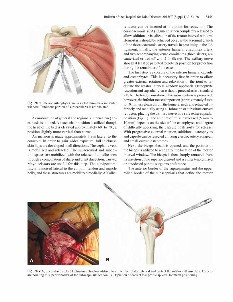
S155Bulletin of the Hospital for Joint Diseases 2015;73(Suppl 1):S154-60
A combination of general and regional (interscalene) an-esthesia is utilized. A beach chair position is utilized though the head of the bed is elevated approximately 60º to 70º, a position slightly more vertical than normal. An incision is made approximately 1 cm lateral to the coracoid. In order to gain wider exposure, full thickness skin flaps are developed in all directions. The cephalic vein is mobilized and retracted. The subacromial and subdel-toid spaces are mobilized with the release of all adhesions through a combination of sharp and blunt dissection. Curved Mayo scissors are useful for this step. The clavipectoral fascia is incised lateral to the conjoint tendon and muscle belly, and these structures are mobilized medially. A Kolbel
retractor can be inserted at this point for retraction. The coracoacromial (CA) ligament is then completely released to allow additional visualization of the rotator interval window. Hemostasis should be achieved because the acromial branch of the thoracoacromial artery travels in proximity to the CA ligament. Finally, the anterior humeral circumflex artery and two accompanying venae comitantes (three sisters) are cauterized or tied off with 2-0 silk ties. The axillary nerve should at least be palpated to note its position for protection during the remainder of the case. The first step is exposure of the inferior humeral capsule and osteophytes. This is necessary first in order to allow greater external rotation and relaxation of the joint to fa-cilitate the rotator interval window approach. Osteophyte resection and capsular release should proceed as in a standard aTSA. The tendon insertion of the subscapularis is preserved; however, the inferior muscular portion (approximately 5 mm to 10 mm) is released from the humeral neck and retracted in-feriorly and medially using a Hohmann or substitute curved retractor, placing the axillary nerve in a safe extra-capsular position (Fig. 1). The amount of muscle released (5 mm to 10 mm) depends on the size of the osteophytes and degree of difficulty accessing the capsule posteriorly for release. With progressive external rotation, additional osteophytes and capsule can be resected utilizing electrocautery, rongeur, and small curved osteotomes. Next, the biceps sheath is opened, and the position of the biceps is utilized to recognize the location of the rotator interval window. The biceps is then sharply removed from its insertion of the superior glenoid and is either tenotomized or tenodesed per the surgeons preference. The anterior border of the supraspinatus and the upper rolled border of the subscapularis that define the rotator
Figure 1 Inferior osteophytes are resected through a muscular window. Tendinous portion of subscapularis is not violated.
Figure 2 A, Specialized spiked Hohmann retractors utilized to retract the rotator interval and protect the rotator cuff insertion. Forceps are pointing to superior border of the subscapularis tendon. B, Depiction of correct low profile spiked Hohmann positioning.
BA

Bulletin of the Hospital for Joint Diseases 2015;73(Suppl 1):S154-60S156
interval are now visualized. Starting laterally, the thin rota-tor interval capsular tissue is excised between these two structures moving in a medial direction until the superior glenoid is encountered. Specially designed low profile spiked Hohmann re-tractors with an angle are inserted anteriorly deep to the subscapularis tendon and posteriorly along the anatomic neck of the humerus deep to the posterior rotator cuff insertion (Fig. 2). Alternatively, a curved posterior rotator cuff retractor can be placed along the posterior anatomic neck and rotator cuff junction. These allow visualization of the anatomic neck of the humerus and protection of the rotator cuff insertion. There are several methods to perform the humeral head cut with an oscillating saw. One method is to perform a free hand cut. An extra-medullary cutting guide with a ver-sion reference can be used as an aid. Through the inferior window, the surgeon’s non-dominant hand can palpate the inferior border of the anatomic neck, and a retractor can be placed at this level to protect the glenoid and axillary nerve from the saw blade. The spiked Hohmann retractor anteriorly demarcates the subscapularis insertion (anterior anatomic neck), and a spiked Hohmann retractor or curved posterior cuff retractor delineates the posterior rotator cuff insertion (posterior anatomic neck), allowing an oscillating saw blade controlled by the surgeon’s dominant hand to safely resect the humeral head at the anatomic neck. Alter-natively, a provisional cut can be made in valgus starting at the anterior supraspinatus insertion behind the bicipital groove to open the intramedullary canal. Since this sets the depth of the humeral component at the junction of the greater tuberosity and the humeral head, an undersized
female broach can be impacted and guide the oscillating saw blade appropriately to make the definitive resection. Finally, if preferred, an extramedullary cutting guide can be assembled and used to estimate the humeral head resection. The free-hand cut best allows a reproduction of the patient’s unique anatomy since version and inclination can be cut precisely based on the patient’s anatomic neck instead of being limited by a guide or female broach. If resected as one piece, the resected humeral head is measured to obtain an estimate of the prosthetic head diameter and thickness. The position of the arm for humeral preparation is dif-ferent than in standard aTSA. By adducting and extending the humerus, optimum exposure of the cut humeral surface is obtained through the rotator interval. The low profile Hohmann retractors are then used to retract the anterior and posterior rotator cuff, thus widening the exposure through the rotator interval. Reaming and broaching are done in a standard fashion, however a modified low-profile broach handle is utilized to facilitate access through the rotator interval. The last size broach is left in the humeral canal with a protective metal disc attached to protect the humeral cut surface during glenoid preparation. The arm is returned to a neutral position and variably externally rotated to allow glenoid exposure. Minimal external rotation is necessary. The glenoid is exposed by placing a two pronged glenoid retractor anteriorly along the scapular neck and a specialized posterior glenoid retractor posteriorly on the edge of the glenoid. A forked “Playboy” retractor is typically useful along the inferior glenoid to lever the humerus inferiorly and posteriorly al-lowing wide exposure of the glenoid face. Soft tissue and capsular release is performed. The glenoid is prepared in standard fashion though an articulating drill and reamer are utilized in cases where exposure is more limited (Fig. 3). Subsequent to preparation, a final standard all polyethylene pegged or keeled component or a caged hybrid glenoid component can be inserted. The glenoid should be inserted before the humeral component is implanted. The arm is again adducted and extended, while the spiked Hohmann retractors are used to retract the margins of the rotator interval. Offset of the humerus is judged by comparing the center of the trial prosthesis to the margins of the humeral cut surface. If there is greater offset, a 4.5 mm modified short replicator plate is used, and if there is minimal offset, a 1.5 mm modified short replicator plate is used. A low profile humeral plate dial is coupled to the short replicator plate. The replicator plate sits in the well of the broach or trial humeral component. Low profile instru-ments are used to rotate the replicator plate and humeral plate dial into the appropriate version, inclination, and offset to yield the best metaphyseal coverage and anatomic restoration. Once the position is satisfactory, a low profile wrench is used to tighten the torque screw. The broach/trial are removed, and the offset of the humeral head relative to the offset of the replicator plate is recorded because this
Figure 3 Exposure is easily obtained through the rotator interval as long as an adequate head resection is done and retractors are appropriately placed.

S157Bulletin of the Hospital for Joint Diseases 2015;73(Suppl 1):S154-60
dual eccentricity will be matched during assembly of the final prosthesis. A back table assembly of the final prosthesis is per-formed. It is assembled to match the trial position and sizes. The replicator plate position is matched (offset, version, and inclination) and secured to the final stem with a torque limiting wrench and torque screw. The humeral head position is dialed to the appropriate offset based on the trial position and impacted in usual fashion to engage the Morse taper. The arm is positioned in adduction and slight external rotation providing improved exposure through the rota-
tor interval. The margins of the rotator interval can be retracted with small Senn retractors. A unique low profile insertion device is used to grasp the assembled prosthesis. The humeral prosthesis is inserted into the intramedul-lary canal at first externally rotated to avoid the coracoid and then gradually internally rotated after the coracoid is cleared (Fig. 4). The insertion handle is impacted until the prosthesis assumes an appropriate position. The position is verified through the inferior window. After irrigation and hemostasis is achieved, the rotator interval is closed starting from lateral to medial with inter-rupted non-absorbable sutures. The inferior subscapularis window can be repaired based on surgeon preference. A drain is used if necessary and depending on surgeon prefer-ence. A sling is provided for comfort only. Active and active-assisted ranges of motion are instituted immediately after surgery, and strengthening is begun once forward elevation to 90° is achieved. Patients can immediately use the arm for activities of daily living (ADL).
Subscapularis Split Operative Technique: Inferior ApproachAn alternative subscapularis sparing approach allows all steps of an aTSA to be performed below the subscapularis without opening the rotator interval. This technique has been previously described for use in humeral head resur-facing by Savoie.9 The patient is placed in a beach chair position. A deltopectoral approach is utilized. Once the subscapularis is identified and the three sister vessels are tied off or coagulated, the lower one-half to lower one-third of the subscapularis is released from the lesser tuberosity (Fig. 5). The humerus is externally rotated allowing the capsule to be released from the inferior humeral neck as far posteriorly as possible. The middle glenohumeral and
Figure 5 A, Anterior view of the subscapularis demonstrating the mid-portion of the tendon (lower blue line) and the upper border of the subscapularis at the rotator interval (upper blue line); B, Illustration of the subscapularis horizontal split provided for clarity.
BA
Figure 4 A specialized low profile prosthesis inserter helps to impact the assembled stem and humeral head into the humeral canal through the rotator interval and around the prominent coracoid.

Bulletin of the Hospital for Joint Diseases 2015;73(Suppl 1):S154-60S158
coracohumeral ligaments are released. A curved rotator cuff retractor is then inserted along the anatomic neck pos-teriorly as the arm is abducted and externally rotated and the humeral head is flipped under the upper subscapularis (Fig. 6). A Chandler retractor placed medially is used to lever the humerus anteriorly. All osteophytes are removed. With this exposure, the humeral head is resected with an oscillating saw similar to a routine subscapularis tenotomy exposure. The humerus is reamed and broached utilizing the standard instrumentation. A trial component is inserted into the intramedullary canal, and the humerus is retracted posteriorly with a bent posterior glenoid retractor while a two pronged anterior retractor is utilized to retract the inferior subscapularis and pectoralis major medially. The arm is placed in abduction and externally rotated. A special bent low profile spiked Hohmann is placed superiorly and used to retract the upper subscapularis superiorly.
The glenoid is prepared in standard fashion, and a hybrid caged pegged glenoid component is impacted into the glenoid after cementing the peripheral peg holes. Next, a Chandler retractor is again used to lever the hu-merus anteriorly. Prior to insertion of the final humeral implant, two drill holes are made on either side of the lesser tuberosity inferiorly, and two #2 braided sutures are passed through these holes for inferior subscapularis repair. The humeral stem is impacted, and the offset, version, and inclination of the head are determined by trialing with a definitive 4.5 mm or 1.5 mm offset rep-licator plate depending on the amount of offset. Once the replicator plate position is set, the humeral head of appropriate size and height is rotated to the correct offset and impacted. The humerus is reduced, and the inferior subscapularis is repaired with the sutures previously passed through bone tunnels with a modified Mason-
Figure 7 Repair of subscapularis split. A combination of modified Mason-Allen stitches and figure of eight stitches with #2 non-absorbable braided sutures are done.
Figure 6 Subscapularis is flipped over the humeral head clearly demonstrating the anatomic neck of the humerus while the head is dislocated inferiorly.

S159Bulletin of the Hospital for Joint Diseases 2015;73(Suppl 1):S154-60
Allen stitch. The horizontal split between the inferior and superior subscapularis is repaired side to side with a #2 braided suture (Fig. 7). A drain is placed based on surgeon preference. Immobilization and therapy progres-sion is similar to the rotator interval approach detailed above.
Discussion Subscapularis tear and dysfunction occur with a significant frequency following aTSA performed with a subscapularis takedown.2-6 Though worse clinical outcomes have been associated with subscapularis insufficiency, failure of subscapularis healing is often clinically silent; therefore, it may be under appreciated. Subscapularis insufficiency is a mode of aTSA failure, and Miller and colleagues reported a 5.8% revision rate after aTSA in a large series.5 Avoiding subscapularis insufficiency is desirable. A subscapularis preserving approach avoids this pitfall and allows aggressive physical therapy and early return to ADLs. Lafosse and coworkers previously described a rotator interval approach to aTSA.7 This technique involved a del-toid split and experienced inadequate osteophyte resection (47%) and humeral head undersizing (29%). This technique did not utilize an inferior window. We believe the rotator interval (with inferior window) and subscapularis splitting techniques detailed above pose a significant advantage over this previously described technique by avoiding a deltoid split and lessening the occurrence of humeral head undersizing and inadequate osteophyte resection. The ad-dition of an inferior subscapularis muscular window in the rotator interval approach allows the surgeon to visualize and resect all osteophytes directly while also ensuring ad-equate humeral head sizing and positioning. In addition, the subscapularis splitting technique allows complete inferior humeral neck visualization for osteophyte resection and sizing. We have not appreciated any clinical sequelae of violating the inferior muscular portion of the subscapularis (10%) with or without its repair at the conclusion of the surgery. Ding and associates reported on the results of the rotator interval approach with an inferior window for osteophyte resection compared to subscapularis tenotomy for aTSA.10 Despite the inferior window, they found sig-nificantly more postoperative osteophytes (p = 0.001) in the subscapularis preserving group (29%) compared to the subscapularis tenotomy group (3%). In addition, although they did not find a significant difference in mean head size discrepancy (difference between prosthetic head diameter and native humeral head diameter) between groups, they did find that the subscapularis preserving group had a greater number of outliers defined as a mismatch larger than 4 mm. Thus, humeral head sizing and osteophyte retention continue to be a concern with the rotator interval technique. The alternative subscapularis split technique allows direct visualization of the humeral anatomic neck facilitating osteophyte resection and humeral head sizing and positioning although sizing of the head superiorly
can become more difficult because of poorer visualization around the rotator interval tissue. There are appreciable differences between the rotator interval and subscapularis split techniques. The main chal-lenges with the rotator interval approach are the difficulty in sizing the humeral head and precisely replicating offset of the humeral head because the window is narrow and requires a back-table assembly of the final prosthesis. However, with experience, this becomes easier and more precise. In addition, the rotator interval technique requires extended retraction on the subscapularis muscle and tendon with indeterminate effects on the muscle and tendon func-tion, though no ill effects have been clinically appreciated. While the subscapularis split allows an en face exposure of the humerus most similar to traditional open surgery and facilitates in situ assembly and precise head positioning, this approach involves tenotomy of the lower one-half to lower one-third of the subscapularis with repair, which may have biomechanical consequences on the strength of the subscapularis. However, Savoie has reported on 50 patients who underwent humeral head resurfacing with a subscapularis splitting approach, releasing the inferior 30% to 50% of the subscapularis. All patients had subscapularis strength equal to the nonoperative side, and there were no radiographic subscapularis failures or cases of subscapularis muscle atrophy.9 We have identified the subscapularis preserving ap-proaches to aTSA detailed above to be safe and reproducible. There is a relatively steep learning curve. This technique should not be used in a revision setting where wide exposure is necessary. Relative contraindications to these techniques include obesity, significant medial glenoid erosion, and situ-ations where glenoid bone grafting is needed. Care should also be taken in patients with severe rotator cuff tendinopathy due to the risk of rotator cuff peel back or iatrogenic injury by overzealous retraction. Future larger studies will examine and report on the clinical and radiographic outcomes of aTSA through sub-scapularis preserving (rotator interval with inferior window and subscapularis split) approaches compared to the standard subscapularis tenotomy, peel, and osteotomy. Furthermore, the rotator interval and subscapularis split approaches will be compared to each other prospectively for clinical outcome, survivorship, and accuracy of anatomic reconstruction. In addition, future studies will evaluate if the percentage of subscapularis release with the subscapularis split technique impacts the strength of the intact portion of the subscapularis and influences the rate of subscapularis healing or failure. Finally, postoperative radiographic studies will be performed to confirm the integrity of the anterior superior rotator cuff tendon insertion and muscle architecture following both subscapularis preserving approaches in a large series.
Conflict of Interest StatementRyan Simovitch, M.D., and Robert Fullick, M.D., are con-sultants for Exactech, Inc., Gainesville, Florida. Joseph D.

Bulletin of the Hospital for Joint Diseases 2015;73(Suppl 1):S154-60S160
Zuckerman, M.D., is a consultant for and receives royalties from Exactech, Inc., Gainesville, Florida.
References1. Kim SH, Wise BL, Zhang Y, Szabo RM. Increasing incidence
of shoulder arthroplasty in the United States. J Bone Joint Surg Am. 2011 Dec 21;93(24):2249-54.
2. Liem D, Kleeschulte K, Dedy N, et al. Subscapularis function after transosseous repair in shoulder arthroplasty: transosse-ous subscapularis repair in shoulder arthroplasty. J Shoulder Elbow Surg. 2012 Oct;21(10):1322-7.
3. Jackson JD, Cil A, Smith J, Steinmann SP. Integrity and func-tion of the subscapularis after total shoulder arthroplasty. J Shoulder Elbow Surg. 2010 Oct;19(7):1085-90.
4. Armstrong A, Lashgari C, Teefey S, et al. Ultrasound evalu-ation and clinical correlation of subscapularis repair after total shoulder arthroplasty. J Shoulder Elbow Surg. 2006 Sep-Oct;15(5):541-8.
5. Miller BS, Joseph TA, Noonan TJ, et al. Rupture of the
subscapularis tendon after shoulder arthroplasty: diagnosis, treatment, and outcome. J Shoulder Elbow Surg. 2005 Sep-Oct;14(5):492-6.
6. Miller SL, Hazrati Y, Klepps S, et al. Loss of subscapularis function after total shoulder replacement: A seldom recognized problem. J Shoulder Elbow Surg. 2003 Jan-Feb;12(1):29-34.
7. Lafosse L, Schnaser E, Haag M, Gobezie R. Primary total shoulder arthroplasty performed entirely thru the rotator inter-val: technique and minimum two-year outcomes. J Shoulder Elbow Surg. 2009 Nov-Dec;18(6):864-73.
8. Simovitch R, Fullick R, Zuckerman JD. Use of the subscapu-laris preserving technique in anatomic total shoulder arthro-plasty. Bull Hosp Jt Dis (2013). 2013;71 Suppl 2:94-100.
9. Savoie FH 3rd, Charles R, Casselton J, et al. The subscapular-is-sparing approach in humeral head replacement. J Shoulder Elbow Surg. 2015 Apr;24(4):606-12.
10. Ding DY, Mahure SA, Akuoko JA, et al. Total shoulder arthro-plasty using a subscapularis-sparing approach: a radiographic analysis. J Shoulder Elbow Surg. 2015 Jun;24(6):831-7.