Bulletin 42- FF / X-383 Protectofier Full Feature...
4
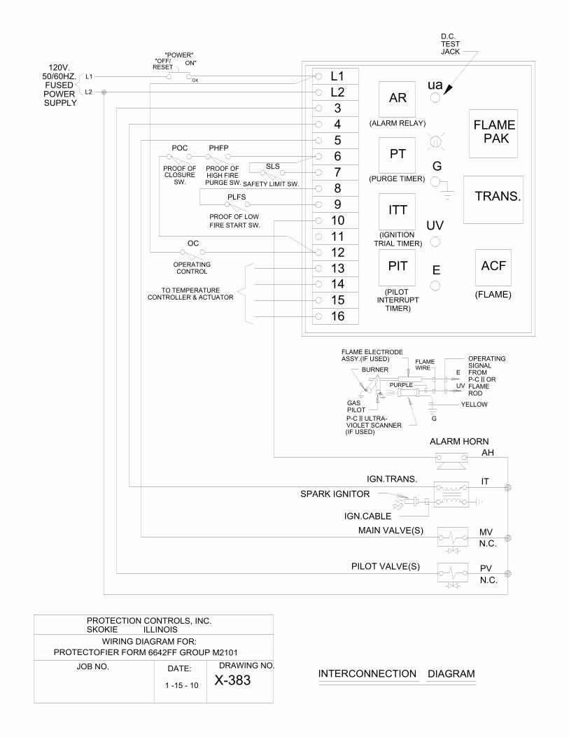
Protectofier COMBUSTION SAFEGUARD FORM 6642FF GROUP M2101 Bulletin 42- FF / X-383 Full Feature Combustion Safeguard including: • Proof of Closure • Proof of High Fire Purge • Purge Timing (In 15 sec. increments to 7¾ min max.) • Proof of Low Fire Start • Ignition Trial Timing (Pilot) 10 sec. • Pilot Interrupt Timing (Main burner ignition trial) 10 or 15 sec. • Alarm output if the safety interlocks (limit switches) or flame failure causes shutdown. • Relay contacts available to drive actuator to high fire for purge, low fire for ignition trial, and control when main burner is proven. • Eight status lights Specifications: 120VAC 50-60Hz 1 Phase 0º to 60ºC 125VA Pilot Duty Dimensions: 8 ½” H X 6 ½” W Form 6642FF in Nema 4/12 Enclosure; Power Off/Reset-On Switch Dimensions: 12” H X 10” W X 6” D OPERATING SEQUENCE ORMAL START SEQUECE 1. Turn Power switch to “On” position. Electrical network is powered from terminal L1. 2. Operating control powers terminal 12. 3. When Proof Of Closure switch(s) and Proof of High Fire Purge Switch (if applicable) are made, terminal 6 is powered. 4. When safety limits (high & low gas pressure, combustion air pressure, high temperature, etc.) are made, terminal 7 is powered. Purge Timer PT is powered. PT purging yellow light is on. Interruption of safety limits results in shutdown. 5. When PT is timed out, its green light illuminates and terminal 8 is powered. N.O. PT contact holds power to PT from Terminal 12. The temperature control actuator drives closed. 6. When Proof of Low Fire Start Switch PLFS is made, terminal 9 is powered. Ignition Trial Timer ITT (10 seconds) and Pilot Interrupt Timer PIT start timing. PLFS is necessary if the actuator is driven to high fire for purge. 7. The ignition transformer is powered from terminal 4 thru N.C. ITT contact. 8. Pilot valve(s) is powered from terminal 3 thru N.C. ITT contact and N.C. PIT contact. If no pilot valve(s) is used, the main fuel valve(s) is powered from terminal 11. 9. When flame is established and is sensed, the SS100A Flame Pak “Amplifier” powers Flame Relay F. N. O. F contact powers terminal 11. 10. When the ITT is timed out, its green light will illuminate. Main valve(s) is powered from terminal 5 thru N.O. F and N.O. ITT contacts. The neon “Flame On” light will illuminate. The ignition transformer will be de- energized. N.O. ITT contact will hold between terminals 8 and 9. 11. 15 (or 10) seconds after the main valve(s) is powered, PIT times out and its green light will illuminate. The pilot valve(s) will de-energize so that the sensor is detecting main burner only. The actuator now goes to the control mode and responds to the temperature controller (modulates). 12. The operating control may turn off the burner. When the operating control powers terminal 12 again, the above sequence is repeated. FAULT SEQUECE 1. If a flame signal is sensed during purge time, PT is de-energized. The alarm relay AR is powered thru N.C. PT contact and N.O. F contact. AR will hold in from terminal L1 thru its own N.O. contact. 2. If a flame is not sensed during the ignition trial time, AR will be powered from terminal 12 thru N.O. ITT and N.C.F contacts. 3. If, after the flame has been proven but at some time later flame signal is lost, AR will be powered from terminal 12 thru N.O. ITT and N.C. F contacts. 4. All Fault sequences listed above lock out the control and may be reset by turning the power switch to “Off/Reset.”
Transcript of Bulletin 42- FF / X-383 Protectofier Full Feature...

Protectofier COMBUSTION SAFEGUARD FORM 6642FF GROUP M2101
Bulletin 42- FF / X-383
Full Feature Combustion Safeguard including:
• Proof of Closure
• Proof of High Fire Purge
• Purge Timing (In 15 sec. increments to 7¾ min max.)
• Proof of Low Fire Start
• Ignition Trial Timing (Pilot) 10 sec.
• Pilot Interrupt Timing (Main burner ignition trial) 10 or 15
sec.
• Alarm output if the safety interlocks (limit switches) or
flame failure causes shutdown.
• Relay contacts available to drive actuator to high fire for purge, low fire for ignition trial, and control when main
burner is proven.
• Eight status lights
Specifications: 120VAC 50-60Hz 1 Phase
0º to 60ºC
125VA Pilot Duty
Dimensions:
8 ½” H X 6 ½” W
Form 6642FF in Nema 4/12 Enclosure; Power Off/Reset-On
Switch Dimensions:
12” H X 10” W X 6” D
OPERATING SEQUENCE
�ORMAL START SEQUE�CE
1. Turn Power switch to “On” position. Electrical network is powered from terminal L1.
2. Operating control powers terminal 12.
3. When Proof Of Closure switch(s) and Proof of High Fire Purge Switch (if applicable) are made, terminal 6 is
powered.
4. When safety limits (high & low gas pressure, combustion air pressure, high temperature, etc.) are made,
terminal 7 is powered. Purge Timer PT is powered. PT purging yellow light is on. Interruption of safety
limits results in shutdown.
5. When PT is timed out, its green light illuminates and terminal 8 is powered. N.O. PT contact holds power to
PT from Terminal 12. The temperature control actuator drives closed.
6. When Proof of Low Fire Start Switch PLFS is made, terminal 9 is powered. Ignition Trial Timer ITT (10
seconds) and Pilot Interrupt Timer PIT start timing. PLFS is necessary if the actuator is driven to high fire for
purge.
7. The ignition transformer is powered from terminal 4 thru N.C. ITT contact.
8. Pilot valve(s) is powered from terminal 3 thru N.C. ITT contact and N.C. PIT contact. If no pilot valve(s) is
used, the main fuel valve(s) is powered from terminal 11.
9. When flame is established and is sensed, the SS100A Flame Pak “Amplifier” powers Flame Relay F. N. O. F
contact powers terminal 11.
10. When the ITT is timed out, its green light will illuminate. Main valve(s) is powered from terminal 5 thru N.O.
F and N.O. ITT contacts. The neon “Flame On” light will illuminate. The ignition transformer will be de-
energized. N.O. ITT contact will hold between terminals 8 and 9.
11. 15 (or 10) seconds after the main valve(s) is powered, PIT times out and its green light will illuminate. The
pilot valve(s) will de-energize so that the sensor is detecting main burner only. The actuator now goes to the
control mode and responds to the temperature controller (modulates).
12. The operating control may turn off the burner. When the operating control powers terminal 12 again, the
above sequence is repeated.
FAULT SEQUE�CE
1. If a flame signal is sensed during purge time, PT is de-energized. The alarm relay AR is powered thru N.C.
PT contact and N.O. F contact. AR will hold in from terminal L1 thru its own N.O. contact.
2. If a flame is not sensed during the ignition trial time, AR will be powered from terminal 12 thru N.O. ITT and
N.C.F contacts.
3. If, after the flame has been proven but at some time later flame signal is lost, AR will be powered from
terminal 12 thru N.O. ITT and N.C. F contacts.
4. All Fault sequences listed above lock out the control and may be reset by turning the power switch to
“Off/Reset.”

ITIGNITION TRANS.
SPARK IGNITOR
PV
N.C.
PILOT VALVE(S)
(NEON LIGHT)
FLAME ON
+
-
+
-
TEMPERATURECONTROL
ACTUATOR
MV
N.C.
MAIN VALVE(S)
L1OC
OPERATINGCONTROL
POC PHFP
12
7
AH
ALARM HORN
"POWER""OFF/ ON"
OX
RESET
L2
AR
AR
ITT F
ITT PIT
PT
ITT
10
11 12
PT
10 12
ITT
13 12
PIT
3
5
11
PIT
ITT
ITT
F
4
ITT
9PLFS
8
PT
13 12
PROOF OFCLOSURE
PROOF OFHIGH FIREPURGESW.
120V. - 50/60 HZ. FUSED POWER SUPPLY
16
PT
15
PT
1413
PIT
AR ALARM RELAY
PT PURGE TIMER
ITT IGNITION TRIAL TIMER
PIT PILOT INTERRUPT TIMER
PIT
LOW FIRE
HIGH FIRE
CONTROL
F
PROOF OF LOWFIRE START SW.
6SLS
SAFETY LIMITINTLKS.
(AS REQ'D.)
PT
ACF
13 12F
CONNECTP-C II UV SCANNEROR FLAME ROD
FLAME RELAY (F)COIL IS ENERGIZEDWHEN FLAME ISESTABLISHED ANDDETECTED.
FLAME PAKELECT.NETWK.
D.C.ua TEST JACK
SW.
AR
1 4
2 55 2
8 2 2 8
7 1
2 8
2 5
1 7
1 4
3 9
7 1
4 1
7 1
7 1
3 6
9 3
6 3
3 9
3 6
AR
9 3
INTERNAL WIRING
EXTERNAL WIRING
SS3CP TRANSFORMER
SS100A FLAME PAK
WIRING DIAGRAM
G
E
UV
HIGH FIRE 13 TO 15
LOW FIRE 13 TO 16
CONTROL (MODULATE) 13 TO 14
POWER ON, OPERATING
CONTROL ON
LIMITSCOMPLETE
POC
PHFP
SAFE STARTCHECK
PLFS
IGNITION
PILOT
MAIN
ALARM
ACTUATOR
DRIVE TO HIGH FIRE DRIVE TO LOW FIRE IGNITION TRIAL ( 10 SEC, )
MAIN IGNITION TRIAL ( 10 SEC. OR 15SEC.)
RUN ALARM
FULL CLOSEDFULL CLOSED
CONTROL MODE
MODULATEFULL OPEN
PURGING (15 SEC. TO 7 3/4 MIN.)
12 TO 66 TO 7
12 TO 6
8 TO 9
4
3
13 TO 16
5
10
13 TO 15 13 TO 14
L1
FLAME PAK
TRANS.
PIT ACF
(FLAME)
D.C.TESTJACK
G
UV
E
L2
3
4
5
6
7
8
9
10
11
12
13
ua
14
15
16
ITT
PT
AR
PROTECTION CONTROLS, INC.SKOKIE ILLINOIS
WIRING DIAGRAM FOR:
JOB NO. DRAWING NO.
PROTECTOFIER FORM 6642FF GROUP M2101
X-3831 -15 - 10
"POWER""OFF/ ON"
OX
RESET
OC
OPERATINGCONTROL
SLS
SAFETY LIMIT SW.
PLFS
PROOF OF LOW
FIRE START SW.
POC PHFP
PROOF OFCLOSURE
PROOF OFHIGH FIREPURGE SW.SW.
L1
L2
INTERCONNECTION DIAGRAM
OPERATINGSIGNALFROMP-C II ORFLAMEROD
GASPILOT
BURNER
FLAME ELECTRODEASSY.(IF USED)
P-C II ULTRA-VIOLET SCANNER
YELLOW
FLAMEWIRE
PURPLE
ALARM HORN
IGN.TRANS.
SPARK IGNITOR
IGN.CABLE
PILOT VALVE(S)
MAIN VALVE(S) MV
PV
N.C.
N.C.
IT
AH
(IF USED)
E
UV
G
120V.50/60HZ.FUSEDPOWER SUPPLY
(ALARM RELAY)
(PURGE TIMER)
(IGNITION
TRIAL TIMER)
(PILOT INTERRUPT
TIMER)
TO TEMPERATURECONTROLLER & ACTUATOR
DATE:

Terms used on drawing:
Operating Control (OC): is an off-on switch which may be a manual selector switch, a temperature
control switch, a time of day switch, or a process control sequence switch.
Proof of Closure (POC): is a switch or switches located on the main fuel valve(s) which is closed when
the valve(s) is closed. See NFPA 86 for valve standards.
Proof of High Fire Purge Switch (PHFP): is an end switch on the temperature control motor or
actuator which is closed when the actuator is in the full open position.
Safety Limit Switches (SLS): include, but not limited to, high gas pressure, low gas pressure,
combustion air pressure, auxiliary contact on combustion blower motor starter, and high temperature.
Proof of Low Fire Start Switch (PLFS): is an end switch on the temperature control motor or actuator
which is closed when the actuator is in the position that allows the optimal, most reliable light-off of the
burner. Do not jumper PLFS (8 to 9) if actuator is driven to high fire for purge.
Note: 1. Contact ratings on above should be suitable to carry loads of ignition transformer and pilot
valve(s) or pilot valve(s) and main valve(s).
2. Purge time shall allow 4 cu. ft. of fresh air per cu. ft. of system volume.
Indicator
Lights
Inputs
Output
7317 N. LAWNDALE AVENUE
P.O. BOX 287 • SKOKIE, ILLINOIS 60076-0287
(847) 674-7676 • CHICAGO PHONE: (773) 763-3110 FAX: (847) 674-7009
www.protectioncontrolsinc.com Printed in USA 0110