BULK ABRASIVE BLASTER - Schmidt Abrasive Blasting …€¦ · · 2015-03-20personnel in the...
94
BULK ABRASIVE BLASTER OPERATION AND MAINTENANCE MANUAL February 2015 SAVE THIS MANUAL AND MAKE AVAILABLE TO ALL USERS OF THIS EQUIPMENT! Manual Part Number 7200-205 (available for downloading from SchmidtAbrasiveBlasting.com) Copyright © 2015 AXXIOM Manufacturing, Inc. 11927 S. Highway 6, Fresno, Texas 77545 800.231.2085 * 281.431.0581 * fax 281.431.1717 Visit us at www.SchmidtAbrasiveBlasting.com
Transcript of BULK ABRASIVE BLASTER - Schmidt Abrasive Blasting …€¦ · · 2015-03-20personnel in the...

BULK ABRASIVE BLASTER
OPERATION AND MAINTENANCE MANUAL February 2015
SAVE THIS MANUAL AND MAKE AVAILABLE
TO ALL USERS OF THIS EQUIPMENT!
Manual Part Number 7200-205 (available for downloading from SchmidtAbrasiveBlasting.com)
Copyright © 2015 AXXIOM Manufacturing, Inc. 11927 S. Highway 6, Fresno, Texas 77545
800.231.2085 * 281.431.0581 * fax 281.431.1717
Visit us at www.SchmidtAbrasiveBlasting.com
Copyright © 2015 Axxiom Manufacturing, Inc.
WARNING 1. Any person intending to operate this equipment or any person intending to be in the vicinity
during its operation must receive proper training from his/her supervisor, employer and/or supplier. If this equipment is to be leased or rented, the supplier must assure that the lessee or renter has received proper training before the lessee or renter takes possession of the equipment. Consult Axxiom Manufacturing, Inc.
2. Any person authorized to operate this equipment or any person intending to be in the vicinity
during its operation and who is not capable of reading and understanding this manual must be fully trained regarding the Rules for Safer Operation and all operating procedures, and must be made aware of all the Dangers, Warnings, and Cautions identified herein. Consult Axxiom Manufacturing, Inc.
3. Do Not operate any abrasive blaster or blast equipment before reading and completely
understanding all the warnings, operating procedures and instructions, and the Rules for Safer Operation contained in this manual.
4. Do Not operate any abrasive blaster or blast equipment without following the Rules for Safer
Operation and all the operating procedures and instructions. Failure to properly use blast equipment could result in serious injury or death.
5. Do Not perform any maintenance on any abrasive blaster or blast equipment while it is
pressurized. Always depressurize the abrasive blaster vessel before loading abrasive or performing any maintenance.
6. Do Not use abrasives containing free silica. Silica can cause silicosis or other related
respiratory damage. All operators must wear personal protective equipment for all abrasive blasting operations. Observe all applicable local, state and federal safety regulations in conjunction with airline filters and respiratory protection. Reference OSHA 29 CFR 1910.134.
7. Do Not enter areas during abrasive blasting operations without breathing protection. All
personnel in the vicinity of abrasive blasting operations should wear NIOSH approved air fed respirators, hoods or helmets.
8. Do Not modify or alter any abrasive blaster, blast equipment or controls thereof without
written consent from Axxiom Manufacturing, Inc.
9. Do Not use bleeder type deadman valves on any Schmidt® abrasive blaster. The use of A-BEC, Clemco or a similar bleeder type deadman valve can cause unintentional start-up without warning, which can result in serious personal injury.
10. Do Not sell, rent, or operate abrasive blasters without remote controls. OSHA regulations require remote controls on all blast machines. Failure to use remote controls can cause serious injury or death to the operator(s) or other personnel in the blasting area. Reference OSHA 29 CFR 1910.244(b).
11. Do Not repair or replace any portion of Schmidt® equipment using components that are not
Schmidt® original factory replacement parts. Use of replacement components that are not Schmidt® original factory replacement parts may result in equipment failure which can result in serious personal injury and in addition will void all warranties.
12. Do Not transport trailer mounted bulk blasters on public roadways with abrasive loaded in
pressure vessel. 13. Do Not tow trailer mounted bulk blasters at speeds exceeding 65 mph.


Safety Bulletin on Closure Safety Systems Purpose Visitors at our booth at the SSPC 2011 conference in Tampa brought to light a concerning situation in our industry. Several people inquired about safety, especially relating to the 10” closures on the top of Bulk Blasting equipment. We were asked many times about the difference in Schmidt’s HALOK Safety System compared to other manufacturers’ “Lock out-Tag out” (LOTO). The patented HALOK is a mechanism that ensures the operator follows the proper Standard Operating Procedure (SOP), whereas a LOTO simply adds another step to the existing SOPs.
Background The original 10" closure on all Schmidt Bulk Blasting equipment built before February 2010 was the safest closure known to us, as long as the proper Standard Operating Procedure was followed. The SOP for the closure states that once the vessel is verified to be depressurized, the operator is to first disengage the cam action handles one at a time. During this process the swing bolts must remain fully engaged in the receiving lugs until all five of the handles are disengaged. The disengagement of the cam action handles allows some vertical movement of the swing bolts, essentially loosening them. The purpose of this is that as long as all five of the swing bolts remain in the receiving lugs, should the vessel still have pressure, the lid will be lifted up until it comes in contact with the nuts on the swing bolts, this lifting action breaks the O-ring seal allowing air to escape, indicating to the operator that the vessel is pressurized and that they are in a dangerous situation. In this condition the operator will experience extraordinary resistance in trying to swing the bolts down due to the receiving lugs being mounted at a slightly upward angle. Should the SOP not be followed and the swing bolts not be retained in the receiving lugs until all five cam lock handles are disengaged, the vessel pressure is capable of, and in fact has, blown the lid off with incredible force causing severe bodily injury and even death. Additionally, some Bulk Blasting units do not have properly operating cam action handles on their closures. A result of this has been operators' using hammers or other objects to forcibly swing the bolts down. This action was the cause of a very tragic accident that required us to testify during the subsequent trial.
HALOK® Safety System The HALOK Safety System, standard on all Schmidt Bulk blasting equipment built after February 2010, is
much more than a Lock out-Tag out. The system is designed to mechanically force the operator to follow the proper SOP for opening the closure. The LOTO mechanisms simply put one further step in the SOP, which requires "authorized" personnel to witness the unit prior to the closure being opened. There is not a single incident,
AXXiom Manufacturing, Inc. 11927 S Highway 6, Fresno TX 77545
TOLL FREE: 800-231-2085 FAX: 281-431-1717
www.Schmidtabrasiveblasting.com

which we are aware of, where an operator was injured or killed who was not considered an "authorized" person.
The HALOK ensures that the swing bolts remain in the receiving lugs until all five of the cam action handles are disengaged. The LOTO does nothing to maintain the swing bolts position in the receiving lugs once it is unlocked.
The HALOK covers the top of the swing bolts in the closed position, preventing the operator from hitting them, effectively acting as a guard while the cam handles are up or engaged.The LOTO does not prevent the operator from forcing the swing bolts out of the receiving lugs once it is unlocked.
The HALOK mandates that while closing the closure, all five of the swing bolts be set into the receiving lugs before any cam action handles are engaged. The LOTO does not address the inherent danger once it is removed. Once removed, you have a closure identical to those involved in several injuries and deaths.
A pneumatic locking system on a LOTO adds an opportunity for mechanical failure without ensuring the closure is opened in a safe manner.

Copyright © 2015 Axxiom Manufacturing, Inc. 1
This manual contains information needed to operate and maintain a Schmidt abrasive blaster. Read this entire operations and maintenance manual before using the abrasive blaster. Pay close attention to the Rules for Safer Operation (Section 1.0), and the Dangers, Warnings, and Cautions identified. The purpose of safety symbols and explanations are to alert operators of the possible hazards and explain how to avoid them. The safety symbols and explanations do not by themselves eliminate any danger. However, following the instructions given and taking proper accident prevention measures will greatly lower the risk of injury to personnel. Below are the three hazard levels as used in this manual.
WHITE LETTERS with RED BACKGROUND DANGER: Indicates an imminently hazardous situation that, if not avoided, will result in death or serious injury. This signal word is limited to the most extreme situations.
BLACK LETTERS with ORANGE BACKGROUND WARNING: Indicates a potentially hazardous situation that, if not avoided, could result in death or serious injury.
BLACK LETTERS with YELLOW BACKGROUND CAUTION: Indicates a potentially hazardous situation that, if not avoided, may result in minor or moderate injury. It may also be used to alert against unsafe practices that may cause property damage. This manual contains terms that may be specific to the abrasive blast industry. Understanding these terms will help operators understand the procedures and instructions given in this manual. All operators must be familiar with the following terms and refer to them as needed while reading this manual.
Term Definition Pressure Vessel
A fabricated tank (or reservoir) that is part of the abrasive blaster which is filled with compressed air and abrasive. (Also referred to as “blast vessel” or “vessel”.)
Pressurize To manually or automatically fill the abrasive blast vessel with compressed air.
Depressurize To manually or automatically release all the compressed air from inside the abrasive blast vessel. (Also referred to as “blowdown”.)
Blowdown To manually or automatically release all the compressed air from inside the abrasive blast vessel. (Also referred to as “depressurize”.)
Deadman A manually operated valve or switch that allows remote starting and stopping of the blast operation. [Also referred to as “deadman valve” (pneumatic blast controls) or “deadman switch” (electric blast controls.)]
Closure A manually operated hinged opening at the top of the bulk abrasive blaster used as the abrasive inlet and as an inspection port.
Abrasive A granular substance used in an air blast operation that is the means for blasting the surface of an object. (Also referred to as abrasive blasting media or media.)
Silica The crystalline chemical compound silicon dioxide (SiO2) which can be found in many natural abrasives and other substances. Breathing silica dust can cause respiratory diseases such as silicosis. (Also referred to as crystalline silica)
Instructions for use of manual sections

Copyright © 2015 Axxiom Manufacturing, Inc. 2
Listed below are the warning decals and the corresponding hazards related to this equipment. Refer to Figure 0.1a and 0.1b for images of the warning decals. Refer to Figure 0.2 for the locations of these warning decals on the bulk abrasive blaster.
No. Qty. Part no. Description Hazard
1. 1 7031-000 Large “Schmidt” Not Applicable
2. 3 7031-054 “Warning”
Airborne particles and loud noise hazards
Airborne particles and loud noise from blast nozzle and blowdown can cause injury and loss of hearing. Wear approved eye and ear protection. See Section 1.0 and 3.10.
3. 2 7031-012A “Danger” Pressurized vessel
Propelled objects will cause serious injury or death. Depressurize vessel before opening closure. See Section 6.2.
4. 2 7031-070 “Safety Instructions”
Propelled objects can cause serious injury or death. Read and understand closure operating procedures before operating this equipment. See Sections 6.2, 6.3, and 6.4.
5. 1 7034-001 Welded “Warning” plate
General hazard and advisory notes.
Steel “Warning” plate welded to pressure vessel which is a general list of required actions to take before and during the operation of this equipment. See Section 1.0.
6. 1 7031-057 “Warning”
Read manual before using this machine.
Read and understand operator’s manual before using this machine. Failure to follow operating instructions could result in injury or damage to equipment. See Section 1.0.
7. 4 7031-009A “Warning” Accident Hazard
Loose wheel can cause loss of vehicle control. Tighten lug nuts frequently. See Section 8.16.
8. 3 7031-007A “Danger” Pressurized vessel
Propelled objects will cause serious injury or death. Depressurize vessel prior to performing any maintenance. See Section 6.2.
9. 1 7031-082 “Danger”
Pressurized vessel Manway components
Propelled objects will cause serious injury or death. Incorrect or damaged handway or manway cover components can result in failure. See Section 6.5.
1) 7031-000 2) 7031-054
Figure 0.1a –Warning decal summary
0.0 Warning Decal Identification and Location

Copyright © 2015 Axxiom Manufacturing, Inc. 3
3) 7031-012A 4) 7031-070 5) 7034-001
6) 7031-057 7) 7031-009A (Trailer mounted units only)
8) 7031-007A 9) 7031-082
Figure 0.1b –Warning decal summary continued

Copyright © 2015 Axxiom Manufacturing, Inc. 4
Figure 0.2 – Warning decal location

Copyright © 2015 Axxiom Manufacturing, Inc. 5
Section Page
0.0 Warning Decal Identification and Location 2 1.0 Rules for Safer Operation 6 2.0 Specifications and General Information 14
3.0 System Requirements and Personal Protective Equipment 19
4.0 Abrasive Blast System General Operation 25 5.0 Abrasive Blaster General Operation 26 6.0 Pre-operation Procedures 33
7.0 Operating Instructions 44
8.0 Maintenance and Inspection Instructions 47 9.0 Drawings and Parts Lists 57 10.0 Recommended Spare Parts Lists 76
11.0 Troubleshooting 77
12.0 Warranty and Reference Information 84
13.0 Blasting Data Tables Back
Table of Contents
Copyright © 2015 Axxiom Manufacturing, Inc. 6
1.1. GENERAL RULE FOR SAFER OPERATION.
THE SCHMIDT® BULK ABRASIVE BLASTER HAS BEEN DESIGNED TO BE SAFE WHEN USED IN THE PROPER MANNER. ALL ABRASIVE BLASTERS ARE POTENTIALLY DANGEROUS IF ALL SAFETY PRECAUTIONS ARE NOT RIGOROUSLY FOLLOWED. PROPER TRAINING IS REQUIRED BEFORE OPERATION. PROPER PROCEDURES MUST BE FOLLOWED. THE ABRASIVE BLASTER AND ALL COMPONENTS MUST BE PROPERLY MAINTAINED. FAILURE TO OPERATE, SERVICE AND MAINTAIN THE ABRASIVE BLASTER AS SET FORTH IN THIS MANUAL MAY CAUSE INJURY OR EVEN DEATH TO ANY PERSON USING, SERVICING OR IN THE VICINITY OF THE ABRASIVE BLASTER. THIS MANUAL IDENTIFIES POTENTIAL HAZARDS BY DANGER, WARNING, AND CAUTION SYMBOLS. HOWEVER, ALL THE RULES, PROCEDURES AND RECOMMENDATIONS MUST BE FOLLOWED. FAILURE TO OPERATE PROPERLY IS VERY LIKELY TO PLACE PERSONS AND PROPERTY AT HIGH RISK OF DAMAGE, INJURY OR EVEN DEATH.
ABRASIVE BLASTERS AND THE ABRASIVE BLAST OPERATION ARE POTENTIALLY DANGEROUS IF ALL SAFETY PRECAUTIONS ARE NOT FOLLOWED. FAILURE TO OPERATE THE ABRASIVE BLASTER WITHOUT FOLLOWING ALL THE RULES FOR SAFER OPERATION MAY RESULT IN SERIOUS INJURY OR DEATH TO OPERATING PERSONNEL OR PERSONS IN THE OPERATING VICINITY.
1.2. KNOW YOUR EQUIPMENT. Do Not operate this equipment in a manner other than its intended application (see Section 4.0).
Do Not operate this equipment or any other Schmidt® equipment without following the Rules for Safer Operation and all the operating procedures and instructions. Learn the applications and limitations as well as the specific potential hazards related to this machine. Failure to do so could result in serious injury or death.
1.3. RECEIVE PROPER TRAINING.
Do Not operate this equipment unless you have received operational and maintenance training. Begin by thoroughly reading and understanding this operation and maintenance manual and all included information. Consult an authorized Schmidt distributor or Axxiom manufacturing, Inc.
1.4. PROTECT YOUR FEET.
Do Not operate this equipment without wearing OSHA approved foot protection. Observe all applicable local, state and federal regulations. See Section 3.10 and OSHA 29 CFR 1910.136.
Heavy objects can shift while being blasted and may fall on operators. All operators and personnel in the vicinity must wear OSHA approved foot protection during the operation of this equipment. See Section 3.10 and OSHA 29 CFR 1910.136.
1.0 Rules for Safer Operation

Copyright © 2015 Axxiom Manufacturing, Inc. 7
1.5. PROTECT YOUR EYES. Do Not operate this equipment without wearing OSHA approved safety glasses. Observe all applicable local, state and federal safety regulations. See Section 3.10 and OSHA 29 CFR 1910.133.
When filling the blast vessel and during the blast operation, abrasive can be blown in the face and eyes of operators. All operators and personnel in the vicinity must wear OSHA approved safety glasses during the operation of this equipment. See Section 3.10 and OSHA 29 CFR 1910.133.
1.6. PROTECT YOUR LUNGS. Do Not operate this equipment without wearing OSHA approved respiratory protection. Abrasive blasting produces dust contaminated with toxic substances from the abrasive used, the coating being removed, and the object being blasted. This dust may contain silica which can cause severe and permanent lung damage, cancer, and other serious diseases. Do Not breathe the dust. Do Not rely on your sight or smell to determine if dust is in the air. Silica and other toxic substances may be in the air without a visible dust cloud. If air-monitoring equipment for silica is not provided at the worksite, then all personnel MUST wear appropriate respiratory protection when using or servicing this equipment. Breathing air supplied to respirators must be of acceptable quality. Consult your employer and OSHA regarding the appropriate respiratory protection and breathing air quality. See Sections 3.9, 3.10, and OSHA 29 CFR 1910.134.
Abrasive blasting produces dust which may contain silica and other toxic substances that can cause severe and permanent lung damage, cancer, and other serious diseases if inhaled. All operators and personnel in the vicinity must wear OSHA approved respiratory protection during the operation of this equipment. See Sections 3.9, 3.10, and OSHA 29 CFR 1910.134.
1.7. BREATHING AIR QUALITY. Do Not use breathing air that does not meet OSHA Class D standards. Use extreme caution when selecting a source of breathing air. Breathing air provided by an oil-lubricated air compressor can contain carbon monoxide; therefore, use of a carbon monoxide detector is required (See Section 3.10). Carbon monoxide can be in the compressed air produced by an oil-lubricated air compressor when it is operated at extremely high temperature; therefore a high temperature alarm is required to alert the operators when this condition exists. See Section 3.9 and reference OSHA 29 CFR 1910.134(i).
Extreme caution must be taken when connecting to factory air sources. Factories can have sources of compressed gases such as nitrogen which is fatal if used as a breathing air source. Verify that the air source is breathable air.
Breathing air must meet OSHA Class D standards. Use of breathing air sources that do not meet Class D standards can cause asphyxiation and result in death. Verify that all air sources are breathable quality and use a high-temperature alarm and a carbon monoxide monitor when required. See Sections 3.9, 3.10 and OSHA 29 CFR 1910.134(i). Enclosed blast areas must be ventilated to reduce airborne dust to an acceptable level as required by OSHA 29 CFR 1910.1000.

Copyright © 2015 Axxiom Manufacturing, Inc. 8
1.8. PROTECT YOUR HEARING. Do Not operate this equipment without wearing OSHA approved hearing protection. Observe all applicable local, state and federal safety regulations. See Section 3.10 and refer to OSHA 29 CFR 1910.95.
Loud noise is generated by the blast nozzle and the blowdown operation of this equipment. All operators and personnel in the vicinity must wear OSHA approved hearing protection during the operation of this equipment. See Section 3.10 and refer to OSHA 29 CFR 1910.95.
1.9. PROTECT YOUR PERSON Abrasive blasting produces dust contaminated with toxic substances from the abrasive used, the
coating being removed, and the object being blasted. All blast operators and other personnel involved in the blast operation or in the vicinity of the blast operation should wear protective clothing. The protective clothing should be disposable or washable work clothes that should be removed at the worksite so that contaminated dust is not transferred into automobiles or homes. See Section 3.10 and refer to OSHA 29 CFR 1910.94 and 1910.134.
1.10. ADHERE TO ALL REGULATIONS.
Do Not operate this equipment without observing all local, state, and federal safety regulations including, but not limited to, OSHA (Occupational Health and Safety Administration).
1.11. STAY ALERT.
Do Not operate this equipment when you are tired or fatigued. Use caution and common sense while operating and/or performing maintenance on this equipment.
1.12. DO NOT USE DRUGS, ALCOHOL, or MEDICATION.
Do Not operate this equipment while under the influence of drugs, alcohol, or any medication.
1.13. PROTECT BYSTANDERS. Do Not allow blast equipment operators and other personnel to enter the vicinity of the blast operation without providing respiratory protective equipment that meets OSHA regulations. If dust concentration levels exceed the limitations set in OSHA 29 CFR 1910.1000 then respirators are required.
1.14. KEEP CHILDREN AND VISITORS AWAY. Do Not allow children or other non-operating personnel to contact this equipment or the connecting hoses and cords. Keep children and non-operating personnel away from work area.
1.15. AVOID DANGEROUS ENVIRONMENTS. Do Not operate this equipment without familiarizing yourself with the surrounding environment. The blast operation creates high level of noise which may prevent the operator from hearing other possible dangers (i.e. traffic or moving equipment). In such situations a stand-by watch person may be necessary to protect against injury to personnel.
1.16. AVOID DANGEROUS ENVIRONMENTS.
Do Not use this equipment in areas cluttered with debris. Debris in the work area can create tripping hazards which can cause the operator to loose control of the blast hose and result in injury to operating personnel. Keep work area clean and well lit. When working at an elevated location, pay attention to articles and persons below.
Copyright © 2015 Axxiom Manufacturing, Inc. 9
1.17. AVOID DANGEROUS ENVIRONMENTS. Do Not operate this equipment in elevated areas without using fall protection equipment. Certain applications of this equipment may require the use of scaffolding. Use of scaffolding creates hazardous situations such as tripping and fall hazards which can result in serious injury or death to operating personnel. Consult OSHA 29 CFR 1910 Subpart D.
1.18. AVOID DANGEROUS ENVIRONMENTS. Do Not blast objects that are not properly secured. The blast operation can cause the blasted object to shift or move. Extremely large objects to be blasted can create a crush hazard to operating personnel which can result in serious injury or death. Properly secure the object to be blasted.
1.19. AVOID DANGEROUS ENVIRONMENTS. Do Not blast objects used to store flammable materials. The blast operation can cause sparks which can ignite fumes or residual flammable materials inside enclosed containers which can explode resulting in serious injury or death to operating personnel.
1.20. ELECTRICALLY GROUND EQUIPMENT. Static electricity is generated by the abrasive flow through the blast hose. To protect against static electrical shock to operating personnel only use static dissipating blast hose and install a grounding strap on the abrasive blaster. See Section 5.12.
1.21. MAINTAIN VESSEL INTEGRITY. Do Not operate this equipment with the pressure vessel damaged, or with any part of it worn or
damaged. Do Not operate this equipment in a condition that may cause failure of the pressure vessel. See Rules 1.22 through 1.34 below.
An abrasive blaster is a Pressurized Vessel. Alterations, damage, or misuse of the pressure vessel can result in rupturing. Damaged or incorrect components used on the abrasive blaster can result in rupturing. The compressed air inside a pressurized vessel contains a dangerously high level of energy which can propel objects and cause serious injury or death.
1.22. NEVER OPERATE OVER MAXIMUM WORKING PRESSURE. Do Not operate this equipment above maximum allowable working pressure (MAWP) at
maximum operating temperature (°F) shown on the ASME nameplate attached to the vessel. See Section 2.2 and 8.1.
1.23. INSTALL PRESSURE RELIEF DEVICE.
Do Not operate this equipment without a pressure relief device in place. The ASME Code requires that all vessels be equipped with pressure relief devices prior to installation. The pressure relief device must be set at the maximum allowable working pressure of the abrasive blaster. See the ASME nameplate attached to the vessel typically located above the manway. See Section 3.11 for information regarding the pressure relief valve.
1.24. NEVER OPERATE BEYOND ALLOWABLE TEMPERATURE RANGE. Do Not operate this equipment above the maximum allowable temperature at the allowable pressure or below the minimum design metal temperature (MDMT) shown on the pressure vessel nameplate. The characteristics of the pressure vessel metal are weakened when the temperature is outside the operating range. Operating the pressure vessel outside of allowable temperature range can result in rupturing and cause serious injury or death.

Copyright © 2015 Axxiom Manufacturing, Inc. 10
1.25. ASME NAMEPLATE REQUIRED. Do Not operate this equipment if the ASME pressure vessel nameplate is missing. Contact Axxiom Manufacturing, Inc. for technical support.
1.26. DO NOT MODIFY VESSEL. Do Not modify or alter any abrasive blaster, blast equipment, or controls thereof without written consent from Axxiom Manufacturing, Inc. Do Not weld, grind, or sand the pressure vessel. It will not be safe to operate. Non-authorized modifications could lead to serious injury or death. Non-authorized modifications will void the warranty and the ASME/NB integrity.
1.27. DO NOT HAMMER ON VESSEL. Do Not hammer on or strike any part of the pressure vessel. Hammering on the pressure vessel can create cracks and cause rupturing.
1.28. FIRE DAMAGE NOTICE. Do Not operate if the pressure vessel has been damaged by fire. If damaged, take out of service immediately and have it inspected and/or repaired by a qualified facility. Contact Axxiom Manufacturing, Inc. for technical support.
1.29. INSPECT VESSEL REGULARLY. Do Not operate this equipment with damage to the pressure vessel. It is not safe. Inspect outside and inside of the pressure vessel regularly for corrosion or damage (i.e. dents, gouges or bulges). If damaged, take out of service immediately and have it inspected and/or repaired by a qualified facility. Contact Axxiom Manufacturing, Inc. for technical support. See Section 8.0.
1.30. CHECK FOR LEAKS IN VESSEL. Do Not operate this equipment if there is a leak in the pressure vessel. If leaking, take out of service immediately and have it inspected and/or repaired by a qualified facility. Contact Axxiom Manufacturing, Inc. for technical support. See Section 8.0.
1.31. INSPECT CLOSURE ASSEMBLY. Do Not operate the closure assembly without first inspecting the camlock handle assemblies and all other parts for proper working condition. See Section 8.4 and 8.5.
1.32. INSPECT MANWAY ASSEMBLY.
Do Not operate the abrasive blaster without first inspecting the manway assembly. To insure proper operation all manway components must be the correct size for the vessel manway opening. See Section 6.5.
1.33. NEVER MODIFY BLOWDOWN. Do Not connect the blowdown on this equipment onto a common header with any other unit of
any description, or any other source of compressed air, without first making sure a check valve is used between the header and this unit. Do Not install this equipment sharing piping with another unit of higher discharge pressure and capacity. A safety hazard could occur in the form of a back-flow condition. Do Not install a muffler or silencer on the blowdown that is not designed for use on abrasive blast equipment it can cause a malfunction and can result in a hazardous condition.

Copyright © 2015 Axxiom Manufacturing, Inc. 11
1.34. DEPRESSURIZE VESSEL BEFORE PERFORMING MAINTENANCE. Do Not remove, repair, or replace any item on this equipment while it is pressurized. Do Not
attempt to perform maintenance or load abrasive while this equipment is pressurized or is even capable of being pressurized. This means the inlet ball valve should be closed and the air supply should be shut off or disconnected. Anytime the manual blowdown valve is closed it should be assumed that the abrasive blast vessel is pressurized.
An abrasive blaster is a Pressurized Vessel. The compressed air inside a pressurized vessel contains a dangerously high level of energy which can propel objects and cause serious injury or death. Depressurize vessel before performing any maintenance. See Section 6.2.
1.35. ALWAYS USE REMOTE CONTROLS. Do Not sell, rent, or operate abrasive blasters without remote controls. OSHA regulations
require remote controls on all abrasive blasters. All abrasive blasters must be equipped with automatic (deadman) type remote controls (either pneumatic or electric). Failure to use remote controls can cause serious injury or death to the operator(s) or other personnel in the blasting area. Reference OSHA 29 CFR 1910.244(b).
1.36. NEVER USE BLEEDER TYPE DEADMAN VALVES. Do Not use bleeder type deadman valves on any Schmidt® abrasive blaster. The use of A-BEC, Clemco, or a similar bleeder type deadman valve can, without warning, cause unintentional start-up which can result in serious personal injury. A particle of dirt from the air hose can plug the bleed hole in the deadman valve and cause the blast outlet to turn on.
1.37. CHECK FOR DAMAGED PARTS. Do Not use this equipment with damaged components. Periodically check all valves, hoses,
fittings, pipe and pipe fittings (internal and external) to see that they are in good condition. Repair or replace any component that shows any sign of wear, leakage, or any other damage. See Section 8.0.
Damaged components can fail during operation and result in serious injury or death to operating
personnel.
1.38. ALWAYS USE SAFETY PINS ON HOSE COUPLING CONNECTIONS. Do Not use this equipment without hose coupling safety pins in place and hose whip checks
installed on all air and blast hoses. All blast hose couplings and air hose couplings have pin holes that must be safety pinned to protect against accidental disconnections. Accidental hose disconnection can cause serious injury or death. See Section 5.14 and 8.7.
1.39. ALWAYS USE CORRECT REPLACEMENT PARTS AND ACCESSORIES. Do Not use replacement parts or accessories that are not rated for pressures equal to or higher than the abrasive blaster’s operating pressure. Improper hoses and/or fittings used on, or connected to the abrasive blaster can rupture and cause serious injury or death.
Do Not use replacement parts that are not Schmidt® original factory replacement parts. Non-original parts may not fit properly and can cause equipment damage and/or failure which can result in serious injury to operating personnel. Consult Axxiom Manufacturing, Inc.
Use of replacement components that are not Schmidt® original factory replacement parts may result in equipment failure which can result in serious injury to operating personnel.

Copyright © 2015 Axxiom Manufacturing, Inc. 12
1.40. ALWAYS USE CORRECT PRESSURE RATED ACCESSORIES. Do Not use air reservoirs or moisture separator tanks that are not rated for use in compressed air applications. Air reservoirs and moisture separator tanks larger than 6 inches inside diameter must have an ASME code stamp.
An air reservoir or moisture separator tank is a Pressurized Vessel. The compressed air inside a pressurized vessel contains a dangerously high level of energy which can explode propelling objects and result in serious injury or death to operating personnel. Air reservoir and moisture separator tanks must be ASME coded tanks.
1.41. NEVER AIM BLAST NOZZLE TOWARDS ANY PERSON.
Do Not aim the blast nozzle towards yourself or any person. A system malfunction or a blocked blast nozzle that clears can trigger accidental start up resulting in injury to personnel.
1.42. NEVER USE ABRASIVE NOT INTENDED FOR BLAST EQUIPMENT. Do Not use abrasive blast media containing free silica. Silica can cause silicosis or other related
respiratory damage. Verify that the abrasive is intended for use in blasting equipment. Personal protective equipment, including airline filters and respirators, must be used for all abrasive blasting operations. Observe all applicable local, state and federal safety regulations. See Section 3.8, 3.10, and reference OSHA 29 CFR 1910.134.
1.43. CHECK ABRASIVE FOR DEBRIS. Do Not use blast abrasive that contains trash or other debris. Trash or debris can create a blockage and cause equipment malfunction. Screen recycled abrasive to remove trash.
1.44. STOP OPERATION IMMEDIATELY IF ANY ABNORMALITY IS DETECTED. Do Not operate this equipment if anything abnormal is seen during operation. Stop operation immediately for inspection. Refer to Section 8.0 for maintenance and inspection details.
1.45. DO NOT OVERLOAD THE LIFT EYES. Do Not load the lifting eyes above the rated capacity. Do Not lift the blast vessel by any point other than the lifting eyes. Do Not lift the blast vessel while it is pressurized. See Section 2.6.
1.46. DO NOT CLIMB ON TOP HEAD. Do Not climb on the top head of the abrasive blast vessel. All parts of the top head, including the closure for abrasive filling, are fully accessible from the ladders that are provided for that purpose. Under no circumstances should the top head be climbed on, stood on, or walked on. The curved surface of the top head is for holding air pressure and is not a work surface.
1.47. TIGHTEN WHEEL LUG NUTS PERIODICALLY. Do Not transport the bulk abrasive blaster before retightening the wheel lug nuts. This is most important after the first load when the lug nuts are establishing a seat. On new highway trailer mounted units transported on public roads, it is recommended that the lug nuts be re-torqued after the first fifty miles and periodically thereafter. See Section 8.16.
1.48. TIGHTEN PRESSURE VESSEL MOUNT BOLTS PERIODICALLY. Do Not transport the bulk abrasive blaster before retightening the pressure vessel mount bolts. On new highway trailer mounted units transported on public roads, it is recommended that the mount bolts be re-torqued after the first fifty miles and periodically thereafter. See Section 8.17.

Copyright © 2015 Axxiom Manufacturing, Inc. 13
1.49. DO NOT SIDE LOAD BULK ABRASIVE BLASTER TRAILER. Do Not exert side loads on the trailer wheels. An example of side loading would be pushing the trailer mounted bulk abrasive blaster on its side with a fork lift or other similar heavy equipment. Move the bulk abrasive blaster only by pushing or pulling at the hitch or brake actuator.
1.50. CLOSE BRAKE LINE BALL VALVE BEFORE BACKING UP. (On units with hydraulic brakes only) Do Not attempt to back up before closing ball valve (#15) on brake line since the backward pressure will activate brakes. See Section 9.3(a).
1.51. DO NOT EXCEED TRAILER AXLE RATING. Do Not load the bulk abrasive blaster with abrasives that will load the axles above the manufacturer’s load rating. The trailer load capacity is designed for use of abrasives with a bulk density of 100 pounds per cubic foot. For abrasives of higher density reduce the volume of abrasive loaded into pressure vessel. See Section 2.2.
1.52. DO NOT HAUL YARD TRAILERS ON PUBLIC ROADS. Do Not tow yard trailer mounted bulk abrasive blasters on public roads. Only highway trailers which are equipped with hydraulic or electric brakes, wheels fenders, and lights are permitted on public highways. Consult local state DOT requirements.
1.53. DO NOT HAUL TRAILER MOUNTED BULK ABRASIVE BLASTER LOADED. Do Not tow trailer mounted bulk abrasive blasters on public roads with abrasive loaded inside of vessel. Highway trailers are rated for transporting abrasive at low speeds only (15 mph).
1.54. DO NOT EXCEED 65 MPH TRAILER SPEED. Do Not tow highway trailer mounted bulk abrasive blasters at speeds exceeding the 65 mph tire rating. Replacement tires must be of equivalent speed and load ratings. See Section 9.3.
1.55. DO NOT TRANSPORT BLAST EQUIPMENT LOADED WITH ABRASIVE.
Portable abrasive blasters are not intended to be moved or transported loaded with abrasive. Do Not attempt to roll portable abrasive blasters with abrasive loaded in or on the pressure vessel as equipment damage or personal injury may result.
1.56. MAINTAIN WARNING DECALS.
Do Not remove, cover, obstruct, or paint over any warnings, cautions, or instructional material attached. Warning decals must be installed, maintained, and located to be visible and with enough light for legibility. See Section 0.0 and 8.13.
1.57. SAVE THIS OPERATION AND MAINTENANCE MANUAL. Refer to this operation and maintenance manual as needed as well as any additional information included from other manufacturers. Never permit anyone to operate this equipment without having him/her first read this manual and receive proper training. Make this manual readily available to all operating and maintenance personnel. If the manual becomes lost or illegible replace it immediately. This operation and maintenance manual should be read periodically to maintain the highest skill level; it may minimize chance of a serious accident.
1.58. SAFETY REFERENCES
See Section 12.4 for safety information sources and contact information. Use these sources to obtain additional information regarding all aspects of blast operation safety.

Copyright © 2015 Axxiom Manufacturing, Inc. 14
2.1 Notes To Distributors and Owners
2.1.1. Remove the manway cover and verify that the deadman, twinlines (or cords), and the operation and maintenance manual are inside the blaster vessel when it is received. Verify that the deadman, twinlines (or cords), and the operation and maintenance manual are inside the blaster vessel when it is delivered to the purchaser.
2.1.2. Some trailer mounted abrasive bulk blasters are shipped with the trailer wheels
removed. Mount the trailer wheels and torque the wheel nuts per Section 8.16. 2.1.3. This equipment is intended for knowledgeable and experienced users. No person or
persons should be allowed to operate this equipment without first receiving proper training in abrasive blasting operation and use of this equipment.
2.1.4. Immediately notify Axxiom Manufacturing, Inc. of any instances of use of this
equipment in any manner other than the intended application. See Section 4.0. 2.1.5. Only qualified personnel should load and unload this equipment for shipping. Slings or
other lifting devices must only be attached to the designated lifting points. See the lifting diagrams shown in Section 2.6.
2.1.6. For further information contact: Axxiom Manufacturing, Inc. 11927 South Highway 6
Fresno, Texas 77545
Phone: 1-800-231-2085 Fax: 1-281-431-1717 Website: www.SchmidtAbrasiveBlasting.com
2.2 Bulk Abrasive Blasting System Operational Specifications
Maximum Working Pressure 125 or 150 psig @ 250°F (see ASME nameplate) All bulk blasters manufactured after July 2009 are 150 psi standard.
Minimum Metal Temperature -20°F @ 125 or 150 psig (see ASME nameplate) Air Consumption See Section 13.0 table 1 Abrasive Consumption See Section 13.0 table 2 Blast Hose Size See Section 13.0 table 3 Electrical requirements See Section 3.7 Bulk Trailer GVWR Model 120: 12,000 lbs. (Gross Vehicle Weight Rating) Model 160: 16,000 lbs. Vessel Abrasive Capacity Model 120: 22,200 lbs. (stationary static load) Model 160: 22,200 lbs. Bulk Trailer Maximum Speed Yard Trailer: 15 mph Highway Trailer: 65 mph
2.0 Specifications and General Information

Copyright © 2015 Axxiom Manufacturing, Inc. 15
2.3 Important Reference Numbers
Fill in the Bulk Abrasive Blaster model number and serial number in the blank spaces below. These will be used for reference whenever service or maintenance is required.
Bulk Abrasive Blaster Model Number
Bulk Abrasive Blaster Serial Number 2.4 Vessel Information
2.4.1. All pressure vessels used in Bulk Abrasive Blasters are manufactured in strict accordance with the provisions of the ASME Code Section VIII, Div. 1 and are registered with the National Board of Boiler & Pressure Vessel Inspectors, 1055 Crupper Avenue, Columbus, Ohio 43229. Should Manufacturer’s Data Reports be required they may be obtained from the National Board for a small fee.
2.4.2. In order to maintain the high level of quality and quality control used in the manufacture
of this vessel, it is required that any and all welded repairs to this vessel be performed by a reputable shop holding a National Board “R” Stamp and/or an ASME “U” stamp, depending on state or city law. Welding on the vessel performed by welders not properly qualified per the ASME Code voids the ASME/NB integrity of that particular vessel.
2.5 Notes

Copyright © 2015 Axxiom Manufacturing, Inc. 16
2.6(a) Bulk Abrasive Blaster Lifting Diagrams
An abrasive blaster is a Pressurized Vessel. The compressed air inside a pressurized vessel contains a dangerously high level of energy which can propel objects and cause serious injury or death. Depressurize vessel and empty before lifting, moving, or transporting.
Only units manufactured after February 2013 are built with four lift eyes rated for full load lifting as shown below.

Copyright © 2015 Axxiom Manufacturing, Inc. 17
2.6(b) Bulk Abrasive Blaster Dimensional Specifications

Copyright © 2015 Axxiom Manufacturing, Inc. 18
2.6 Bulk Abrasive Blaster Shipping Detail

Copyright © 2015 Axxiom Manufacturing, Inc. 19
Carefully read and follow all the recommendations regarding the abrasive blast system installation requirements. Improper installation can result in equipment malfunction and significant lost time expenses. Consult an authorized Schmidt® distributor or Axxiom Manufacturing, Inc. 3.1 Abrasive Blast System Installation Location
i. Portable units: Units equipped with trailers are portable and can be rolled to locations where blast jobs are performed. Locate the unit to allow accessibility to the manway and for ease of abrasive filling. Pay close attention to objects that may be in the path of the pressure vessel exhaust air (depressurization).
ii. Stationary units: Units that will be installed in permanent locations require careful
consideration. Stationary units can be installed below an abrasive hopper with a support structure that can limit access to the abrasive blast system. Install stationary blast systems in a position that will allow access to the manway and the blaster piping. These areas must be accessible to perform required maintenance. Pay close attention to objects that may be in the path of the pressure vessel exhaust air (depressurization). See Section 6.2. The bulk abrasive blaster manual blowdown valve typically does not have an exhaust hose however; one can be installed to direct the exhaust air flow into a blast room. NOTE: A long blowdown exhaust hose can lengthen the blowdown time and also presents the possibility of blockage. Caution: Units equipped with the CEN Exhaust System are not suited for this modification.
iii. The bulk abrasive blaster is provided with mounting holes in the bottom leg foot pad. These
holes can be used for securing the blaster to the floor or mounting structure.
3.2 Compressed Air Requirements (blast nozzle) The blast nozzle size and blast pressure determine the compressed air requirements. Available air flow capacity and/or air compressor size must be considered before selecting the blast nozzle size. An air source dedicated to the abrasive blast system is preferred to reduce system pressure drops and back flow of air. If an existing air compressor will be used or a limited air supply is available, then the blast nozzle must be selected based on these conditions. Be aware that as the blast nozzle wears the air demand will increase. See Table 1 in Section 13.0 for air consumption by nozzle size at various pressures.
3.3 Air Compressor Size
Air compressor size is crucial to the operation of the abrasive blast system. Blast nozzle selection and desired productivity must be evaluated to determine the air flow requirements prior to selecting the air compressor size. Sufficient air supply capacity is necessary to maintain the system air pressure. Insufficient air flow capacity will result in reduced blast nozzle pressure and lost productivity. The air compressor must be large enough to supply:
i. The sum of blast air requirements for each nozzle at the highest pressure that will be
used (see Section 13.0, Table 1).
ii. The 12 CFM breathing air supplied to each blast operator respirator. NOTE: Reference OSHA regulations regarding requirements for breathing air, especially when an oil-lubricated air compressor is used.
3.0 System Requirements and Personal Protective Equipment

Copyright © 2015 Axxiom Manufacturing, Inc. 20
3.4 Blast System Air Supply Line The air supply hose and fittings must be rated at a minimum of 150 psi operating pressure. The air supply hose from the air compressor to the blast unit should be at least the same diameter as the air inlet piping (see Section 9.0). This size hose will be large enough to supply the required airflow to operate the blast unit controls and each blast nozzle. See Sections 5.11 for further information on air hose connection. NOTE: If the abrasive blast system will be installed in a permanent location the inlet connection can be hard piped. Do Not install hard piping that is smaller than the piping size of the blast system. Smaller piping size will reduce the air flow capacity. If other equipment will be using the same source of air as the abrasive blaster, install a check valve at the air inlet. This will protect against back flow of air pressure that can carry abrasive into the blast controls. Hard piping connected to the abrasive blaster must be structurally supported so not to apply any loading on the pressure vessel at the points of connection. Unsupported piping can create bending loads at the connections on the pressure vessel and cause failure. Hard piping connections to the pressure vessel must be designed and installed by qualified personnel experienced with piping systems and the applicable codes pertaining to them.
External loading at piping connection can cause failure of the pressure vessel. Hard piping connected to the pressure vessel must include rigid supports to eliminate the possibility of applying a load on the pressure vessel.
3.5 Blast System Air Pressure The maximum allowable working pressure (MAWP) for the blast unit is stamped on the ASME nameplate attached to the vessel. For most abrasive blast systems the MAWP is 150psig. Do Not exceed the MAWP. An air pressure regulator can be installed to reduce air supply pressure that is higher than the MAWP. To minimize chance of air pressure backflow only use a non-relieving air regulator. Air pressure backflow will carry abrasive from the blast vessel and contaminate the blast control system. CRITICAL: A regulator with sufficient air flow capacity must be selected for proper operation of the blast system. Insufficient air flow capacity will cause pressure drop in the blast system resulting in equipment malfunction, abrasive backflow, and reduced blast productivity. Select a valve that will operate with little or no pressure drop (3psi max.) at the required cfm air flow. Installing an air pressure regulator allows the option of blasting at low pressure. When blasting at low pressure the air supply to the deadman blast control system must be at least 80psig (see Figure 5.3 and 5.4). The valves in the abrasive blast system are “spring closed” and therefore require at least 80psig to operate properly. If the air pressure regulator is set below 80psig the air supply to the blast controls must be taken upstream of the regulator.
3.6 Blast System Air Quality Air quality is crucial to the operation of an abrasive blaster. Moisture and contaminants can cause components to malfunction. Moisture condensation in a blast system causes abrasive flow problems. Condensation occurs when the hot vapor-filled compressed air cools as it reaches the abrasive blaster. Water droplets formed during condensation can be absorbed by the abrasive in the blast vessel which can cause erratic flow to the abrasive valve. Therefore, a moisture removal device installed for the blast system air supply is recommended (i.e. coalescing moisture separator, air-cooled aftercooler or deliquescent dryer). Contact a local authorized Schmidt® distributor or Axxiom Manufacturing, Inc. to locate one near you.
3.7 Electrical Requirements On units equipped with electric blast controls the supply voltage is 12Vdc or 24Vac. The maximum power required is:
Each outlet: 7 watts Each outlet with abrasive cutoff: 14 watts 4-outlet: 28 watts 4-outlet with abrasive cutoff: 56 watts
NOTE: Insufficient electric power output will result in malfunctioning of the electric blast control system. A power transformer or power supply can be used if the above voltages are not readily available

Copyright © 2015 Axxiom Manufacturing, Inc. 21
3.8 Abrasive Selection Abrasive selection is likely the most difficult decision related to the blast operation. Choice of abrasive is based on factors such as blast application type, desired finish and coating requirements, characteristics of object to be blasted, cost and ability to recycle, available equipment, safety, and environmental constraints.
There are many abrasives available that are either natural, manufactured, or processing by-products. Abrasives are available in varying sizes, shapes, and hardness. These characteristics determine the resulting effect on the surface to be blasted and limitations of its use. The effects on the blasted surface are measured by its degree of cleanliness and the surface profile. Standards and required levels of these measurements are established by organizations such as Steel Structures Painting Council (SSPC), National Association of Corrosion Engineers (NACE) and coating manufacturers. See Section 12.5 for contact information of these organizations. Use these sources to obtain information regarding all aspects of surface preparation and abrasive selection guidelines.
The Thompson Valve and Micro Valve abrasive blasters are designed for high production open abrasive blasting with a wide range of abrasives. It is the responsibility of the employer and operators to select the proper abrasive. It is the responsibility of the employer to make certain that the abrasive selected is safe to use for abrasive blasting.
CRITICAL: Always obtain the Material Safety Data Sheet (MSDS) for the abrasive to be used. The MSDS provides the chemical makeup of the abrasive. Do Not use abrasives containing toxic materials. Refer to OSHA 29 CFR for acceptable limits of various toxic substances and additional measures to be taken to protect operating personnel. Always use abrasives containing less than 1% of crystalline silica. Always use a NIOSH approved respirator when handling, loading and cleaning up abrasives. Organic substances which are combustible may only be used in automated blast systems with ventilation that meets OSHA 29 CFR 1910.94.
3.9 Breathing Air Quality
All blast operators must be supplied with and required to use NIOSH approved air-fed respirators. Breathing air supplied to these respirators must meet Grade D air quality standards as specified by OSHA 29 CFR 1910.134(i) and the Compressed Gas Association Specifications ANSI/CGA G-7.1. Consult these specifications when selecting a source of breathing air. Breathing air must be clean, dry, contaminant-free, and provided at a pressure and volume specified by NIOSH. Use NIOSH approved air filters on all sources of breathing air. See Section 3.10.
Breathing air filters do not remove carbon monoxide or any other toxic gases. Use a carbon monoxide monitor to detect unacceptable levels. Consult OSHA 29 CFR 1910.134(i).
Many sources of breathing air are available such as air cylinders, free-air pumps, oil-less air compressors, and oil lubricated air compressors. The most commonly used is the same air compressor that is used for the blast air which most often is oil lubricated. Breathing air provided by an oil-lubricated air compressor can contain carbon monoxide and therefore requires the use of a carbon monoxide detector (See Section 3.10). Carbon monoxide can be in the compressed air produced by an oil-lubricated air compressor when it is operated at extremely high temperature; therefore, a high temperature alarm is required to alert the operators when this condition exists.
Oil lubricated air compressors can produce carbon monoxide. Carbon monoxide can cause asphyxiation and result in death. Use a high-temperature alarm and a carbon monoxide monitor when an oil lubricated air compressor is used to supply breathing air. Consult OSHA 29 CFR 1910.134(i).

Copyright © 2015 Axxiom Manufacturing, Inc. 22
3.10 Personal Protective Equipment (PPE) Abrasive blasting has many hazards that may cause injuries to operators. To protect operators from injury each must be supplied with and required to use Personal Protective Equipment. The Occupational Health and Safety Administration (OSHA) requires the employer to assess the workplace to determine what PPE is necessary and supplied to each operator (Reference 29 CFR 1910 Subpart I). OSHA requires that this equipment meet or be equivalent to standards developed by the American National Standards Institute (ANSI). Figure 3.10 below identifies the minimum personal protective equipment required for each abrasive blast operator. Also identified are the OSHA references for each and the ANSI standard each PPE item must meet. All PPE clothing and equipment should be selected for safe design and quality of construction. Select each for proper fit and for comfort which will encourage operator use.
Figure 3.10 - Personal Protective Equipment

Copyright © 2015 Axxiom Manufacturing, Inc. 23
3.11 Pressure Relief Valve Installation Do Not operate this equipment without a pressure relief device installed to protect the blaster pressure vessel from over-pressurization. The ASME Code requires that all vessels be operated with pressure relief devices in place. If the compressed air system does not provide for the installation of a pressure relief valve one can be installed on the blowdown port on the pressure vessel. Refer to Figure 3.11 for an alternate location of the air pressure relief valve.
Local regulations set the specifications for pressure relief valves; therefore it is the responsibility of the owner of the abrasive blaster to install a pressure relief valve that meets all applicable regulations. The pressure relief device must be set at the maximum allowable working pressure of the abrasive blaster pressure vessel See the ASME/CE vessel nameplates attached to the pressure vessel.
Rupture Hazard. Operating the pressure vessel above the maximum allowable working pressure can result in rupturing the pressure vessel. Install an air pressure relief valve to protect against over pressurization of the blast vessel.
Airborne particles and loud noise hazards from relief valve exhaust air can cause serious injury and loss of hearing. Wear approved eye and ear protection. Stay clear of exhaust air path. DO NOT place hands or other body parts in the exhaust air path. Make sure no personnel are in the exhaust air path. Direct the relief valve exhaust away from work area.
Figure 3.11 – Suggested location for air pressure relief valve

Copyright © 2015 Axxiom Manufacturing, Inc. 24
3.12 INSTALLATION CHECKLIST (Photocopy this page to use as a worksheet)
□ Deadman/Twinline (or cords): confirm delivery with the abrasive blaster.
□ Manway covers & crab assemblies: confirm delivery with the abrasive blaster.
□ Blast accessories: confirm receipt as purchased with the blaster.
□ Inspect blaster: check for possible damage during shipment. See Section 8.0 for inspection instructions.
□ Closure assembly: inspect closure and camlock handle assemblies. See Section 8.4 for inspection & adjustment instructions.
□ Clean blaster: remove manway cover and check for debris inside. Trapped debris can vibrate loose during shipment and later block abrasive flow. If necessary vacuum the bottom of tank. Replace manway cover per instructions in Section 6.5.
□ Install trailer wheels: mount and torque the wheels per Section 8.16.
□ Accessible location: install stationary blasters so that the manway is accessible for maintenance. See Section 3.1 for additional information.
□ CFM available: determine available air supply (cfm) and record here. See Sections 3.2, 3.3, and 3.5 for information on determining air requirements.
□ Air supply connection: install air supply piping or connect an air supply hose that is the same size as the air inlet size or larger. See Section 3.4 for details.
□ Air quality: install moisture separator or AirPrep System to remove moisture from blast air supply to protect against abrasive flow problems. See Section 3.6.
□ Electric power: provide power for electric deadman controls. See Section 3.7.
□ Blast abrasive: select abrasive suited for application. See Section 3.8.
□ Breathing air: provide Grade D air source for blast operators. See Section 3.9.
□ PPE: provide all the necessary personal protective equipment. See Section 3.10.
□ Pressure relief valve: install relief valve if not provided on air compressor. See Section 3.11 for information on pressure relief valve installation.
□ Blast nozzle: select size based on available cfm noted above. See Section 3.2 & 5.13.
□ Blast hose: select size three times the nozzle size that will be used. See Section 5.12.
□ Operator training: all operators must completely read and understand the operation and maintenance manual and be properly trained in equipment and blast operations.
□ Abrasive Blaster Setup: follow procedures in Section 6.1.

Copyright © 2015 Axxiom Manufacturing, Inc. 25
The function of the Schmidt® abrasive blaster is to provide a mixture of dry abrasive and compressed air to a blast nozzle. The abrasive blast stream through the blast nozzle is used for removing rust, paint, or other unwanted surface defects. After abrasive blasting, the surface is ready for new paint or coating.
The Bulk Abrasive Blaster is one of a group of components used in an abrasive blasting job. The typical components are an air compressor, moisture removal device, an abrasive blaster, blast hose, a blast nozzle, operator personal protective equipment, and blast abrasive. See Figure 4.1.
The blast abrasive is loaded into the abrasive blaster through a top fill port. All the compressed air must be removed from inside the abrasive blaster before it can be filled with abrasive. The abrasive can be bag loaded, or loaded from a Schmidt storage hopper. To begin blasting the fill port is closed and the abrasive blaster is filled with compressed air from the air compressor. Since moisture creates problems in the blast operation, it is common for the compressed air to be fed through a moisture removal device, such as a Schmidt Air Prep System. The air pressure in the abrasive blast vessel is equal to the air pressure in the blast hose where it connects at the Thompson Valve®. This equal pressure is needed to allow the blast abrasive to flow downward by gravity. The abrasive flow is controlled by the Thompson Valve at the bottom of the blaster. At this point, the blast abrasive flows into the blast air stream and through the blast hose. The speed of blast air and abrasive mixture is greatly increased by the blast nozzle onto the work surface. The high speed of the air and abrasive is what gives it the energy to blast rust and paint off of surfaces. The abrasive blast stream and the dust it creates is harmful, therefore all blast operators must use personal protective equipment during the blast operation.
All the components required for the blast operation (except for the air compressor) are available from Axxiom Manufacturing, Inc. Call Axxiom to locate a distributor.
Figure 4.1 – Typical Bulk Abrasive Blast System
4.0 Abrasive Blast System General Operation

Copyright © 2015 Axxiom Manufacturing, Inc. 26
See Figure 5.1 below or Figure 8.7 (page 56) to help understand the general operation. Do not attempt to operate the bulk abrasive blaster before reading all sections of this manual and following all setup procedures. See Sections 5.1 through 5.14 and Section 6.0.
The Bulk Abrasive Blaster (#4 & #8) will pressurize when the blowdown ball valve (#15) is closed and the air inlet ball valve (#7) is opened. The compressed air enters the moisture separator (#8) and then is branched off to the blast outlets and to pressurize the bulk abrasive blast vessel (#4).
Blasting begins when the deadman lever (#1) is pressed down which will pneumatically or electrically open the blast control valve (#12). When the control valve opens it sends an air signal that opens both the automatic air valve (#10) and the Thompson Valve® (#13). Compressed air will pressurize the blast hose (#19) when the automatic air valve (#10) is opened. At the same time the Thompson Valve (#13) will open and abrasive falls through and into the blast air stream. The abrasive flow can be increased or decreased by turning the knob (#20) on top of the Thompson Valve.
Blasting stops when the deadman lever (#1) is released. This will close the blast control valve (#12) and vent the air signal to the automatic air valve (#10) and the Thompson Valve (#13). When the signal air vents both valves spring return to the “normally closed” position. The Bulk Abrasive Blaster (#4 & #8) remains pressurized when the air and the metering valves are turned off. The Bulk Abrasive Blaster (#4 & #8) is depressurized by closing the air inlet ball valve (#7) and opening the blowdown ball valve (#15) to completely vent the compressed air.
Figure 5.1 – Typical Bulk Abrasive Blaster
5.0 Abrasive Blaster General Operation

Copyright © 2015 Axxiom Manufacturing, Inc. 27
5.1 Closure (abrasive inlet) The blaster is filled with abrasive through the closure abrasive inlet at the top of the pressure vessel. The closure is a manually operated 10” hinged opening that is opened only when the blast vessel is depressurized. Refer to Section 6.2 for depressurization procedure. The closure is opened and closed by following the procedures detailed in Sections 6.3 and 6.4. Note: Bulk Abrasive Blasters manufactured after January 2010 are equipped with the Halok® System (#25) that guides the operator through the proper opening procedure. See Section 6.2 and 9.13.
The closure is part of a Pressurized Vessel. Propelled objects will cause serious injury or death. Depressurize vessel before opening closure. See Section 6.2.
5.2 Air Supply Connection
Air is supplied to the abrasive blaster through a hose connection at the air inlet crowfoot (#2). The air supply hose connected to the abrasive blaster must be same diameter as the air supply piping and rated at a minimum of 150psi operating pressure. See the drawings and parts lists in Section 9.0 and refer to Section 5.14.
5.3 Air Inlet Ball Valve (pressurize) The air inlet ball valve (#7) is used to turn on and turn off the air flow to the abrasive blaster. Air enters the blaster through a hose connection at the air inlet crowfoot (#2). The air then passes through the moisture separator (#8) and into the blast vessel (#4). When the air inlet ball valve is opened the air flow will pressurize the blast vessel (#4 & #8). Note: Units manufactured after November 2013 include a lockout feature on the inlet ball valve to stop air flow into the bulk abrasive blaster. Then depressurize per Section 6.2 to disable.
5.4 Blowdown Ball Valve (depressurize) The blowdown ball valve (#15) is used to release all the compressed air (depressurize) from inside the abrasive blaster. The abrasive blaster must be depressurized before filling with abrasive or before performing any maintenance. The air inlet ball valve (#7) must be closed before depressurizing the abrasive blaster (See Section 6.2). Note: Bulk Abrasive Blasters manufactured after January 2010 are equipped with the CEN Exhaust System. The CEN nozzle (#26) controls the exhaust air flow and minimizes freezing of the blowdown ball valve (#15). The system also includes a muffler to reduce the noise level of the exhaust air.
Airborne particles and loud noise hazards from blowdown exhaust air can cause serious injury and loss of hearing. Wear approved eye and ear protection. Stay clear of blowdown air path. DO NOT place hands or other body parts in the blowdown air path. Make sure no personnel are in the blowdown air path.
5.5 Moisture Separator
Air flow into the blaster passes through the moisture separator (#8) which removes moisture, oil and dirt particles from the inlet air. The water that is removed by the separator is drained by opening the ball valve (#6) at the bottom of the separator. This ball valve should be left slightly opened anytime the blaster is in operation. This allows water to be drained as it is filtered from the blast air. After passing through the moisture separator, the air branches off to supply the blast controls (#9, #10, & #12) and pressurizes the bulk abrasive blast vessel (#4). Note: Blasters not equipped with a moisture separator are furnished with a pipe manifold.

Copyright © 2015 Axxiom Manufacturing, Inc. 28
5.6 Choke Valve The choke valve (#9) is a ball valve located in the blast air line upstream of the Thompson Valve®. The choke valve (#9) is used to clear any trash that may get into the blast vessel and block the Thompson Valve orifice. Whenever trash (paint chip, cigarette butt, etc.) blocks the Thompson Valve orifice the procedure is to fully open the Thompson Valve knob, then press down the deadman lever (#1) to begin blasting. While blasting, have an assistant close the choke valve completely for about one second. This creates differential pressure at the Thompson Valve (high pressure above; low pressure below). The higher pressure from the blast vessel should be enough to loosen the trash blocking the Thompson Valve orifice and blast it through the blast nozzle (#21). To minimize excess wear of the Thompson Valve keep the choke valve fully open during normal blasting. Note: If the bulk abrasive blaster is equipped with the abrasive cut-off feature set the cut-off valve (or switch) to the on-position for the choke procedure. See Sections 9.11 and 9.12.
Do not aim blast nozzle towards yourself or any person. System malfunction can cause accidental start up and result in injury to personnel. A secondary purpose of the choke valve is as a manual shut off valve for the blast air supply. When the choke valve (#9) is closed it will shut off the blast air supply to the blast outlet.
5.7 Automatic Air Valve (blast air valve)
The automatic air valve (#10) is a normally closed valve that opens to supply blast air to the blast hose and blast nozzle (#19 & #21). The automatic air valve opens when it receives air to its signal port. This happens when the deadman lever (#1) is pressed down which opens the blast control valve (#12) sending an air signal to the automatic air valve. When the deadman lever is released the air signal from the blast control valve vents and automatic air valve spring closes to stop blast air to the blast hose and nozzle. See Section 9.7. Note: Bulk Abrasive Blasters manufactured after July 2008 are equipped with the High Flow Automatic Air Valve that provides increased air flow capacity for larger blast nozzles.
Figure 5.1 – Typical Bulk Abrasive Blaster

Copyright © 2015 Axxiom Manufacturing, Inc. 29
5.8 Thompson Valve® II (abrasive metering valve) The Thompson Valve (#13) is a dual-purpose valve. First, it is a normally closed valve that opens to supply abrasive into the blast air stream. The Thompson Valve opens when it receives air to its signal port (See Sections 9.4 and 9.5). This happens when the deadman lever (#1) is pressed down which opens the blast control valve (#12) sending an air signal to the Thompson Valve. When the deadman lever is released the air signal from the blast control valve vents and Thompson Valve spring closes to stop abrasive flow to the blast hose and nozzle (#19 & #21). Secondly, the Thompson Valve® (#13) is an abrasive metering valve. When the Thompson Valve is open the abrasive flow is metered (controlled) by an adjustable orifice. The amount this orifice opens is controlled by turning the knob (#20) at the top of the Thompson Valve. The knob sets the stopping point of the plunger (See Section 9.4 & 9.5). Turn the knob clockwise to reduce the orifice size which decreases abrasive flow. Turning the knob counter-clockwise increases the orifice size which will increase the abrasive flow to the blast nozzle (#21). The Thompson Valve spring retainer has lines on the side to use as reference points to the amount that the orifice is open. Adjustments to the abrasive flow should be made by turning the knob a little at a time. Test the adjustment by starting the blast for a short period to determine if further adjustment is needed.
The Thompson Valve II has a built in cleanout port where a ball valve can be installed (see Section 9.5). This ball valve can be used to purge (blow out) trash that blocks abrasive flow. This is done by closing the union ball valve (#24), opening the clean out valve, and then pressing down the deadman lever (#1). The blast air flows through the Thompson Valve and purges any trash through the clean out valve. Note: If the abrasive blaster is equipped with the abrasive cut-off feature set the cut-off valve (or switch) to the on-position for the Thompson Valve® to open for purging. See Sections 9.11 and 9.12.
Airborne particles and loud noise hazards from purge air can cause serious injury and loss of hearing. Wear approved eye and ear protection. Stay clear of purge air path. DO NOT place hands or other body parts in the purge air path. Make sure no personnel are in the purge air path.
5.9 Union End Ball Valve (abrasive shutoff) The union ball valve (#24) is an optional valve that allows the user to remove the Thompson Valve from the blast vessel without emptying the abrasive. Turn the union ball valve handle to the horizontal position to block abrasive flow from the blast vessel (#4) into the Thompson Valve. Then loosen the nut to separate the two sections of the union ball valve and remove the Thompson Valve from blast vessel. The handle on the union ball valve can be difficult to turn at times; however there are punched holes at each arm of the handle where a standard ratchet wrench can be inserted and used as leverage to open or close the valve. Note: Units manufactured after January 2015 include the ergonomic round handle design (see Figure 5.2). Note: Purging the abrasive from the Thompson Valve will minimize chance of seizing of the union nut allowing it to turn freely.
The bulk abrasive blaster is a Pressurized Vessel. Propelled objects will cause serious injury or death. Depressurize vessel before performing any maintenance. See Section 6.2.

Copyright © 2015 Axxiom Manufacturing, Inc. 30
Figure 5.2 – Union End Ball Valve
5.10 Deadman Valve/Switch
The Deadman valve/switch is part of a system that controls the blast operation. The deadman valve/switch (#1) allows the operator to remotely start and stop the blast operation. The Deadman is mounted at the end of the blast hose assembly (#19) close to the blast nozzle (#21) to give the operator easy control of the blast operation. The Deadman is either a pneumatic valve or an electric switch depending on the type of abrasive blaster control system. When the deadman lever is pressed down it sends either a pneumatic or electric signal to the blast control valve (#12). The control valve opens and sends an air signal to the automatic air valve (#10) and the Thompson Valve (#13). See Sections 9.1, 9.2, 9.8 and 9.9. 5.10.1. Pneumatic Deadman System: When the pneumatic deadman lever is pressed down air supply from the orange hose of the twinline hose (#17) flows into the black hose. Air flows through the black hose to the signal port of the control valve (#12) causing it to open and send air signals to the auto air valve (#10) and the Thompson Valve® (#13). When the deadman lever is released the air signal is cut off and the remaining air vents from the breather (#11). See Figure 5.3 and the drawing in Section 9.1.
Figure 5.3 – Pneumatic Blast Control System

Copyright © 2015 Axxiom Manufacturing, Inc. 31
5.10.2. Electric Deadman System: When the electric deadman lever is pressed down it closes the electric circuit and supplies electric current to the control valve (#12). The control valve opens and sends air signals to the auto air valve (#10) and the Thompson Valve® (#13). When the deadman lever is released the electric circuit is cut off closing the control valve. The signal air vents from the breather (#11). See Figure 5.4 and the drawing in Section 9.2.
Figure 5.4 – Electric Blast Control System
5.11 Abrasive Cut-Off An optional feature of a blaster is an abrasive cut-off. The purpose of the abrasive cut-off is to allow blasting air without abrasive. This is useful for blowing off abrasive from the blasted item. To blast with air only set the abrasive cut-off valve (or switch) to the off-position then press down the deadman lever (#1). This will send a control signal to the automatic air valve only; therefore, only blast air will exit the blast nozzle (#21). For the abrasive cut-off to work a second control valve is needed that provides a signal to the Thompson Valve® separate of the air signal to the automatic air valve. Refer to the drawings in Sections 9.11 and 9.12.
5.12 Blast Hose
The blast air and abrasive mixture flows from the Thompson Valve® to the blast nozzle (#21) through the blast hose assembly (#19). The typical length of the blast hose is 50ft; however blast hose extensions can be added to increase length. For higher efficiency keep the blast hose as short as possible. Increased blast hose length causes pressure drop at the blast nozzle which reduces the blast efficiency. For higher efficiency use a blast hose with an inside diameter that is approximately three times the nozzle throat diameter. Keep blast hose as straight as possible. Sharp bends create high wear points. Static electricity is generated by the abrasive flow through the blast hose. To protect against static electrical shock to operating personnel only use static dissipating blast hose and install a grounding strap on the abrasive blaster.
Static electric shock hazard. To protect against static electric shock install a grounding strap on the abrasive blaster and only use static dissipating blast hose.
Longer blast hoses require longer time to dissipate the blast stream when the deadman is released to end the blast operation. This extended dissipation time increases the risk of injury should there be an accidental loss of control of the blast hose.

Copyright © 2015 Axxiom Manufacturing, Inc. 32
5.13 Blast Nozzle The blast nozzle (#21) is an important part of the blast operation since the size of it determines the air flow and abrasive requirement. The amount of air flow and abrasive determine how quick blasting can be done. The larger the nozzle, the more the air and abrasive will be needed. The larger the nozzle size the greater the blast productivity. However, for a fixed amount of air supply, increasing the nozzle size will reduce the blast pressure. For best performance the blast pressure must be maintained as high as possible. Therefore, select the nozzle size based on the amount of air available and then adjust the abrasive flow at the Thompson Valve® as needed.
The nozzle size can be identified by a small number visible on the outside. This number represents the nozzle throat diameter in sixteenths of an inch; for example, a #5 nozzle has a throat diameter of 5/16". See the tables in Section 13.0 for approximate air and abrasive consumption for each nozzle. Note: For the best possible mixture of air to abrasive, the blast hose and piping must be at least three times the size of the blast nozzle.
5.14 Hose Connection
All air hose, blast hose, and threaded couplings have pin holes that align when connected. To protect against accidental hose disconnections safety pins must be installed through these holes. As a secondary safety measure each hose connection should also include a hose whip check that will hold the hose if there is an accidental disconnection. Connect one loop to each side of the connection and stretch out as shown in Figure 5.5 below. All air hose, blast hose, and threaded couplings have a gasket that seals the connection and should be replaced when air is leaking.
Failure to install safety pins on all blast and air hose couplings could result unintentional disconnection and cause serious injury or death.
Figure 5.5 – Hose Connection Disconnect Protection

Copyright © 2015 Axxiom Manufacturing, Inc. 33
Failure to follow the procedures below could result in serious injury or death. In addition to these procedures, completely read and understand all sections of this Bulk Abrasive Blaster Operation and Maintenance Manual.
The closure assembly is part of a Pressurized Vessel. Propelled objects will cause serious injury or death. Depressurize vessel before opening the closure assembly. 6.1 Bulk Abrasive Blaster Setup Procedure (see Figure 6.2 or Figure 8.7)
6.1.1. Confirm that the bulk abrasive blaster is properly maintained and inspected as detailed
in Section 8.0. 6.1.2. Static electricity is generated by the abrasive flow through the blast hose. To protect
against static electrical shock to operating personnel only use static dissipating blast hose and install a grounding strap on the abrasive blaster.
Static electric shock hazard. To protect against static electric shock install a grounding strap on the abrasive blaster and only use static dissipating blast hose.
6.1.3. Do Not operate this equipment without a pressure relief device in place. The ASME
Code requires that all vessels be provided with pressure relief devices. See Section 3.11.
Rupture Hazard. Operating the pressure vessel above the maximum allowable working pressure can result in rupturing the pressure vessel. Install an air pressure relief valve to minimize chance of over pressurization of the blast vessel. See Section 3.11.
6.1.4. Do Not operate this equipment without the pressure indication ball valve (#23) in place. This is an added feature that allows the operator to verify that the bulk abrasive blaster is completely depressurized before attempting to open the closure. See Figure 6.2.
6.1.5. Make certain that the bulk abrasive blaster is not pressurized. Follow the depressurizing procedure given in Section 6.2.
Airborne particles and loud noise hazards from blowdown exhaust air can cause serious injury and loss of hearing. Wear approved eye and ear protection. Stay clear of blowdown air path. DO NOT place hands or other body parts in the blowdown air path. Make sure no personnel are in the blowdown air path.
6.1.6. Thoroughly understand the operation of the closure before using the bulk abrasive
blaster. See the closure opening and closing procedures given in Section 6.3 and 6.4.
6.1.7. Properly install the manway cover and gasket. See Section 6.5.
6.0 Pre-operation Procedures

Copyright © 2015 Axxiom Manufacturing, Inc. 34
6.1.8. Verify that all required personal protective equipment is available for each operator and in good operating condition (safety glasses, safety shoes, ear plugs, gloves, airline filter, respirator, & carbon monoxide monitor). Critical: Adhere to all local, state, and federal regulations including, but not limited to, OSHA (Occupational Health and Safety Administration). Pay close attention to requirements regarding breathing air quality. When an oil-lubricated air compressor is used, additional requirements for a high temperature alarm and/or a carbon monoxide monitor become necessary. See Sections 3.9 and 3.10.
Failure to use personal protective equipment could result in serious injury or death.
6.1.9. Hose clamp the deadman (#1) onto the blast hose assembly in a comfortable position
behind the nozzle holder. Then tie wrap the twinline hose or electric deadman extension cords to the blast hose (#19). On new units the deadman, twinline, or extension cords are placed inside the pressure vessel for shipping.
6.1.10. Screw nozzle (#21) into the nozzle holder at end of the blast hose assembly (#19).
6.1.11. Connect the blast hose coupling to the threaded coupling (#18) on the metering valve
(#13). Then install safety pins and a hose whip check to minimize chance of accidental disconnections during operation. See Sections 5.14 and 8.7.
Failure to install safety pins on all blast hose couplings could result in serious injury or death. See Sections 5.14 and 8.7.
6.1.12. Connect the twinline hose quick disconnects (#17) or the electric deadman extension
cords to the mating disconnects on the bulk abrasive blaster piping.
Be sure that each twinline is connected to the control valve disconnects (#12), automatic air valve (#10), and Thompson Valve® (#13) that supply the blast hose (#19) attached to it. If the blaster has electric controls, each must be connected to the matching junction box pigtail. See the drawings in Sections 9.1 and 9.2. Close all choke valves (#9) and abrasive shutoff valves (#24) then check that all connections are correct by pressing down each deadman lever to test.
On abrasive blasters with multiple outlets care must be taken while connecting the twinline hoses or electric deadman extension cords so not to cross connect them. Each must be connected to the matching blast outlet control. Cross connecting will result in unintentional blast startup and could result in serious injury or death.
6.1.13. Connect a 150 psi rated (minimum) air supply hose to the air inlet crowfoot (#2) and
install safety pins and a hose whip check to minimize chance of accidental disconnections during operation. See Sections 5.14 and 8.7.
Failure to install safety pins on all air hose couplings could result in serious injury or death. See Sections 5.14 and 8.7.

Copyright © 2015 Axxiom Manufacturing, Inc. 35
6.1.14. The following steps only apply to abrasive blasters with electric blast control systems. 6.1.15. Connect the electric power cord (#41) to the blaster junction box connector (#43).
6.1.16. Connect the electric power cord alligator clips (#40) to the air compressor battery
terminals or to another 12Vdc power source. See Figure 6.1.
Electric shock hazard. Abrasive blasters with electric deadman blast control systems must operate on low voltage supply (12-24 volts). To protect against electric shock only use low voltage sources and use caution when connecting the power supply to the abrasive blaster. See Section 3.7.
Figure 6.1 – Electric power connection

Copyright © 2015 Axxiom Manufacturing, Inc. 36
6.2 Bulk Abrasive Blaster Depressurizing Procedure (Blowdown)
Do not leave the abrasive blaster pressurized during long periods of no usage. Undetected air leaks can cause costly wear damage to the pressure vessel (i.e. at abrasive inlet and manway). 6.2.1. Close the air inlet ball valve (#7). The ball valve is closed when the handle is fully
turned to the position shown in Figure 6.2 (handle perpendicular to body). The handle tab will bottom against the ball valve body in the closed position.
6.2.2. Slowly and completely open the blowdown ball valve (#15) located near the bulk
abrasive blaster manway (#16). This will depressurize the bulk abrasive blaster (#4 & #8). The exhaust air flow is controlled and muffled by the CEN system (#26). The CEN Exhaust System minimizes freezing at the blowdown and reduces noise level. Note: The CEN System is standard on Schmidt® bulk blasters manufactured after February 2010.
Airborne particles and loud noise hazards from blowdown exhaust air can cause serious injury and loss of hearing. Wear approved eye and ear protection. Stay clear of blowdown air path. DO NOT place hands or other body parts in the blowdown air path. Make sure no personnel are in the blowdown air path.
6.2.3. The blowdown ball valve (#15) should be inspected for proper operation before each use of the abrasive blaster. Confirm that the blowdown ball valve handle turns open and closed without difficulty. See Section 8.0 for maintenance details.
6.2.4. The bulk abrasive blast vessel (#4 & #8) is completely depressurized when the air inlet
ball valve (#7) is closed and the blowdown ball valve (#15) is open with no airflow from it. Air flow is indicted by movement of the muffler rain cap (#27). Note: Confirm that the blaster is depressurized by opening the pressure indication ball valve (#23) and checking for air flow. CAUTION: Air flow indicates that there is air pressure in the blast vessel (#4). Repeat above procedure and check for faulty components. See Section 8.0 for maintenance details.
Figure 6.2 – Typical Bulk Abrasive Blaster
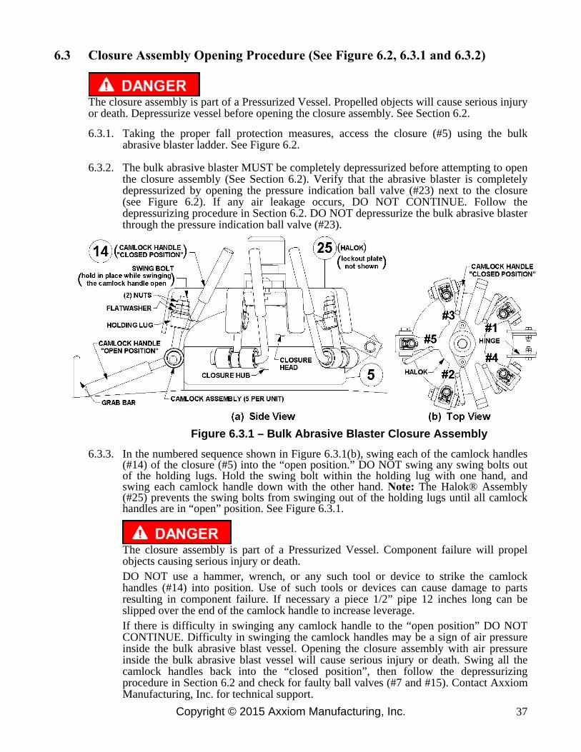
Copyright © 2015 Axxiom Manufacturing, Inc. 37
6.3 Closure Assembly Opening Procedure (See Figure 6.2, 6.3.1 and 6.3.2)
The closure assembly is part of a Pressurized Vessel. Propelled objects will cause serious injury or death. Depressurize vessel before opening the closure assembly. See Section 6.2.
6.3.1. Taking the proper fall protection measures, access the closure (#5) using the bulk abrasive blaster ladder. See Figure 6.2.
6.3.2. The bulk abrasive blaster MUST be completely depressurized before attempting to open the closure assembly (See Section 6.2). Verify that the abrasive blaster is completely depressurized by opening the pressure indication ball valve (#23) next to the closure (see Figure 6.2). If any air leakage occurs, DO NOT CONTINUE. Follow the depressurizing procedure in Section 6.2. DO NOT depressurize the bulk abrasive blaster through the pressure indication ball valve (#23).
Figure 6.3.1 – Bulk Abrasive Blaster Closure Assembly
6.3.3. In the numbered sequence shown in Figure 6.3.1(b), swing each of the camlock handles (#14) of the closure (#5) into the “open position.” DO NOT swing any swing bolts out of the holding lugs. Hold the swing bolt within the holding lug with one hand, and swing each camlock handle down with the other hand. Note: The Halok® Assembly (#25) prevents the swing bolts from swinging out of the holding lugs until all camlock handles are in “open” position. See Figure 6.3.1.
The closure assembly is part of a Pressurized Vessel. Component failure will propel objects causing serious injury or death.
DO NOT use a hammer, wrench, or any such tool or device to strike the camlock handles (#14) into position. Use of such tools or devices can cause damage to parts resulting in component failure. If necessary a piece 1/2” pipe 12 inches long can be slipped over the end of the camlock handle to increase leverage.
If there is difficulty in swinging any camlock handle to the “open position” DO NOT CONTINUE. Difficulty in swinging the camlock handles may be a sign of air pressure inside the bulk abrasive blast vessel. Opening the closure assembly with air pressure inside the bulk abrasive blast vessel will cause serious injury or death. Swing all the camlock handles back into the “closed position”, then follow the depressurizing procedure in Section 6.2 and check for faulty ball valves (#7 and #15). Contact Axxiom Manufacturing, Inc. for technical support.
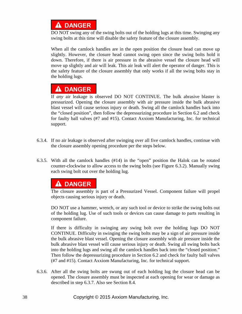
Copyright © 2015 Axxiom Manufacturing, Inc. 38
DO NOT swing any of the swing bolts out of the holding lugs at this time. Swinging any swing bolts at this time will disable the safety feature of the closure assembly. When all the camlock handles are in the open position the closure head can move up slightly. However, the closure head cannot swing open since the swing bolts hold it down. Therefore, if there is air pressure in the abrasive vessel the closure head will move up slightly and air will leak. This air leak will alert the operator of danger. This is the safety feature of the closure assembly that only works if all the swing bolts stay in the holding lugs.
If any air leakage is observed DO NOT CONTINUE. The bulk abrasive blaster is pressurized. Opening the closure assembly with air pressure inside the bulk abrasive blast vessel will cause serious injury or death. Swing all the camlock handles back into the “closed position”, then follow the depressurizing procedure in Section 6.2 and check for faulty ball valves (#7 and #15). Contact Axxiom Manufacturing, Inc. for technical support.
6.3.4. If no air leakage is observed after swinging over all five camlock handles, continue with the closure assembly opening procedure per the steps below.
6.3.5. With all the camlock handles (#14) in the “open” position the Halok can be rotated counter-clockwise to allow access to the swing bolts (see Figure 6.3.2). Manually swing each swing bolt out over the holding lug.
The closure assembly is part of a Pressurized Vessel. Component failure will propel objects causing serious injury or death.
DO NOT use a hammer, wrench, or any such tool or device to strike the swing bolts out of the holding lug. Use of such tools or devices can cause damage to parts resulting in component failure.
If there is difficulty in swinging any swing bolt over the holding lugs DO NOT CONTINUE. Difficulty in swinging the swing bolts may be a sign of air pressure inside the bulk abrasive blast vessel. Opening the closure assembly with air pressure inside the bulk abrasive blast vessel will cause serious injury or death. Swing all swing bolts back into the holding lugs and swing all the camlock handles back into the “closed position.” Then follow the depressurizing procedure in Section 6.2 and check for faulty ball valves (#7 and #15). Contact Axxiom Manufacturing, Inc. for technical support.
6.3.6. After all the swing bolts are swung out of each holding lug the closure head can be
opened. The closure assembly must be inspected at each opening for wear or damage as described in step 6.3.7. Also see Section 8.4.

Copyright © 2015 Axxiom Manufacturing, Inc. 39
6.3.7. Each time the closure assembly is opened all the camlock assemblies and hinge assemblies must be inspected for damage, including but not limited to, corrosion, cracks, and deformations. Make sure all the swing bolts, nuts, washers, cams, spring pins, and handles are in place (See Drawing 9.3(a)). Inspect the threads of each swing bolt and (2) nuts for corrosion or wear. Each camlock assembly and hinge must be tested for ease of operation. Any camlock, swing bolt, nut, or hinge that show signs of damage, corrosion, wear, or does not swing freely must be repaired or replaced before re-pressurizing the blast vessel. The camlock handles must be installed into the cam lugs as shown in Figure 6.3.2(b) so there is no interference with closure head handle or hinges and to insure proper operation of the closure Halok® (#25). The torque on the camlock assembly nuts must be properly adjusted. See Sections 8.4 and 8.5 for closure assembly maintenance instructions and adjustment procedures.
The closure assembly is part of a Pressurized Vessel. Component failure will propel objects causing serious injury or death.
DO NOT operate the bulk abrasive blaster with a closure assembly that has damaged or worn components. Use of the closure assembly with worn or damaged parts will result in component failure.
Note: Bulk abrasive blasters manufactured after November 2013 may include an optional Halok® lockout that prevents opening of the closure assembly when a locking device is installed. The purpose of the Halok lockout is to disable its operation and thereby protect against unauthorized opening of the closure assembly. See Figure 6.4.2 and Section 9.13.
Figure 6.3.2 – Bulk Abrasive Blaster Closure Assembly

Copyright © 2015 Axxiom Manufacturing, Inc. 40
6.4 Closure Assembly Closing Procedure (See Figure 6.4.1 and 6.4.2)
6.4.1. Inspect the closure head and sealing surface for damage including, but not limited to, corrosion, cracks, or deformations. Check that the 10” o-ring is fitted in the groove at the bottom of the closure head. Remove and inspect the closure o-ring for cuts or tears. Replace if necessary. Replace the o-ring and adjust to remove kinks or twists.
6.4.2. Close the closure head and check for alignment with closure hub. If the closure head does not close properly, do not attempt to pressurize the bulk abrasive blaster. Take the bulk abrasive blaster out of service and have it inspected and/or repaired by a qualified facility. Contact Axxiom Manufacturing, Inc. for technical support.
Do Not operate the bulk abrasive blaster with a closure head that does not close properly. Component failure will result. Component failure will cause serious injury or death.
6.4.3. Each time the closure assembly is opened all the camlock assemblies and hinge assemblies must be inspected for damage, including but not limited to, corrosion, cracks, and deformations. Make sure all the swing bolts, nuts, washers, cams, spring pins, and handles are in place (See Drawing 9.3(a)). Inspect the threads of each swing bolt and (2) nuts for corrosion or wear. Each camlock assembly and hinge must be tested for ease of operation. Any camlock, swing bolt, nut, or hinge that show signs of damage, corrosion, wear, or does not swing freely must be repaired or replaced before re-pressurizing the blast vessel. The camlock handles must be installed into the cam lugs as shown in Figure 6.4.1(b) so there is no interference with closure head handle or hinges and to insure proper operation of the closure Halok® (#25). The torque on the camlock assembly nuts must be properly adjusted. See Sections 8.4 and 8.5 for closure assembly maintenance instructions and adjustment procedures.
The closure assembly is part of a Pressurized Vessel. Component failure will propel objects causing serious injury or death.
DO NOT operate the bulk abrasive blaster with a closure assembly that has damaged or worn components. Use of the closure assembly with worn or damaged parts will result in component failure.
6.4.4. Swing all the swing bolts into position within the holding lug. Be sure each swing bolt has the required (2) nuts and flat washer, and they are in good condition. See Figure 6.4.1.
Do not use a hammer, wrench, or any such tool or device to strike the camlock handles (#14) or swing bolts into position. Use of such tools or devices can cause damage to parts resulting in component failure. Component failure will cause serious injury or death.
6.4.5. After all the swing bolts are in position within the holding lugs rotate the Halok® (#25) clockwise to allow access to the camlock handles (#14). See Figure 6.4.1.
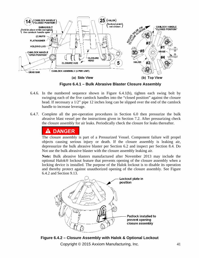
Copyright © 2015 Axxiom Manufacturing, Inc. 41
Figure 6.4.1 – Bulk Abrasive Blaster Closure Assembly
6.4.6. In the numbered sequence shown in Figure 6.4.1(b), tighten each swing bolt by swinging each of the five camlock handles into the “closed position” against the closure head. If necessary a 1/2” pipe 12 inches long can be slipped over the end of the camlock handle to increase leverage.
6.4.7. Complete all the pre-operation procedures in Section 6.0 then pressurize the bulk abrasive blast vessel per the instructions given in Section 7.2. After pressurizing check the closure assembly for air leaks. Periodically check the closure for leaks thereafter.
The closure assembly is part of a Pressurized Vessel. Component failure will propel objects causing serious injury or death. If the closure assembly is leaking air, depressurize the bulk abrasive blaster per Section 6.2 and inspect per Section 8.4. Do Not use the bulk abrasive blaster with the closure assembly leaking air. Note: Bulk abrasive blasters manufactured after November 2013 may include the optional Halok® lockout feature that prevents opening of the closure assembly when a locking device is installed. The purpose of the Halok lockout is to disable its operation and thereby protect against unauthorized opening of the closure assembly. See Figure 6.4.2 and Section 9.13.
Figure 6.4.2 – Closure Assembly with Halok & Optional Lockout

Copyright © 2015 Axxiom Manufacturing, Inc. 42
6.5 Manway Cover Installation Procedure (See Figure 6.5(a))
6.5.1. Check that the manway cover, crabs, bolts, and gasket are dimensionally correct for the size manway weld ring of the pressure vessel.
a) Measure and write down the inside dimensions “A” and “B” of the manway weld
ring. See Figure 6.5(a).
b) Identify the size of the manway assembly by comparing the weld ring measurements from step “a” to the dimensions shown in Table 6.5(c).
c) Verify that the dimensions of the cover, crabs, bolts, and gasket match the
corresponding dimensions given in Table 6.5(c). Note: The actual dimensions may vary by up to 1/4" from those given in Table 6.5(c).
d) Replace any component that is not dimensionally correct. Incorrect dimensions
indicate that the component is part of a different size manway assembly.
The manway assembly is part of a Pressurized Vessel. Use of incorrect manway components will result in assembly failure. Assembly failure will propel objects causing serious injury or death.
6.5.2. Once a month inspect the manway gasket for tears, cracks, or other wear. Replace if
necessary.
6.5.3. Once a month inspect the manway weld ring sealing surface inside the vessel. Inspect the manway cover sealing surface. Both surfaces must be smooth.
6.5.4. Preassemble the bolts through each crab and thread on each nut a couple of turns.
6.5.5. Securely place the gasket on the manway cover fitting it under the Manway Stay
Bracket tabs. The gasket is held in place by the tabs. Refer to Figure 6.5(b). 6.5.6. Fit the cover with gasket through the manway opening.
6.5.7. Place the cover and gasket in position against the inside edge of the manway weld ring
with the long tab of the Manway Stay Bracket at the bottom of the weld ring as shown in Figure 6.5(a) Front View. Apply a pulling force to hold in position then proceed.
6.5.8. The Manway Stay Bracket centers the gasket and cover over the manway weld ring.
Rotate the cover left or right until the long tab of the Manway Stay Bracket is level horizontally.
6.5.9. Slide each manway crab w/bolt into cover bracket slot until the bolt bottoms at the
inside edge. Loosely tighten each nut. See Figure 6.5(a) and 6.5(b).
6.5.10. When all components are centered and the crab bolts are bottomed in the slots, tighten the nuts and bolts with a wrench until they are snug.
6.5.11. Only after completing all the pre-operation procedures in Section 6.0 and the bulk
abrasive blast vessel is then pressurized, re-tighten the nuts and bolts with a wrench until they are snug again.
6.5.12. Do not over-tighten the crab nuts and bolts. Over-tightening could bend the crab out of
shape resulting in malfunction of the assembly.
6.5.13. Periodically check for leaks.
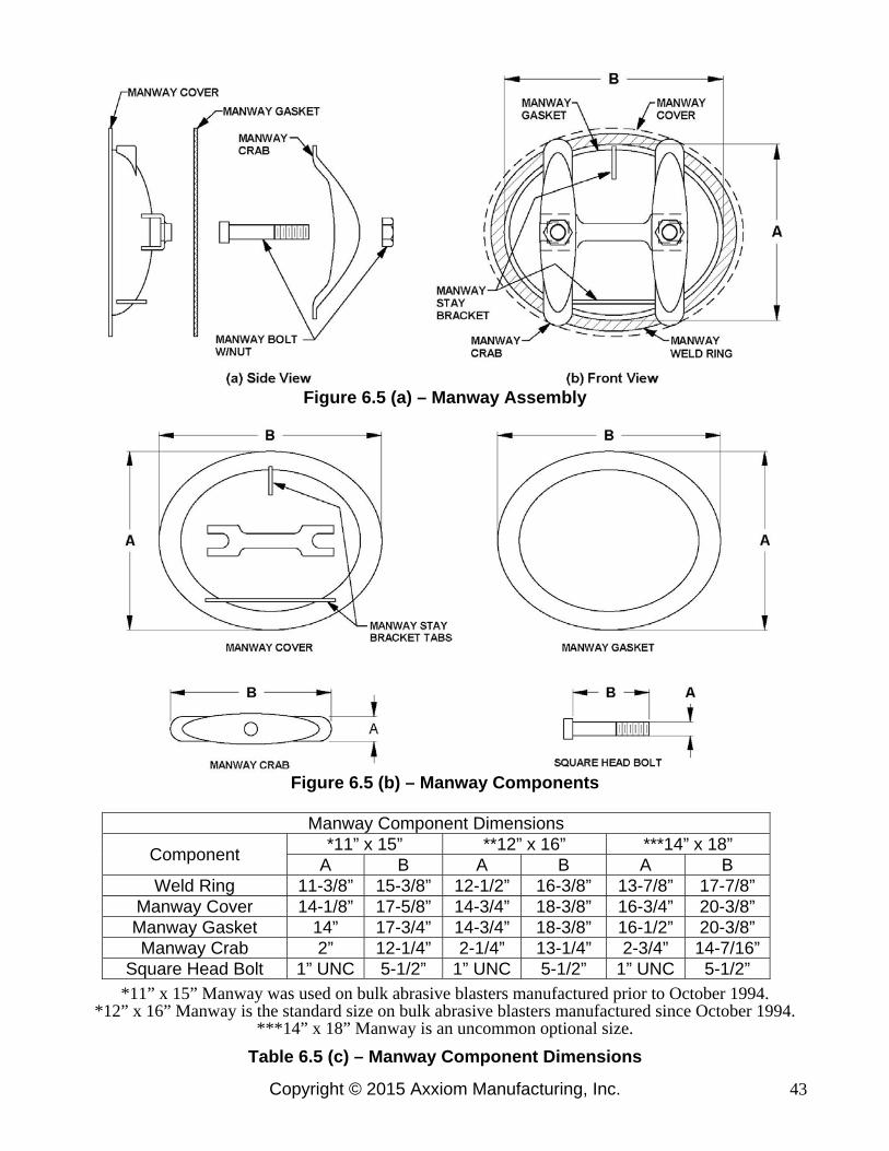
Copyright © 2015 Axxiom Manufacturing, Inc. 43
Figure 6.5 (a) – Manway Assembly
Figure 6.5 (b) – Manway Components
Manway Component Dimensions
Component *11” x 15” **12” x 16” ***14” x 18”
A B A B A B Weld Ring 11-3/8” 15-3/8” 12-1/2” 16-3/8” 13-7/8” 17-7/8”
Manway Cover 14-1/8” 17-5/8” 14-3/4” 18-3/8” 16-3/4” 20-3/8” Manway Gasket 14” 17-3/4” 14-3/4” 18-3/8” 16-1/2” 20-3/8” Manway Crab 2” 12-1/4” 2-1/4” 13-1/4” 2-3/4” 14-7/16”
Square Head Bolt 1” UNC 5-1/2” 1” UNC 5-1/2” 1” UNC 5-1/2” *11” x 15” Manway was used on bulk abrasive blasters manufactured prior to October 1994.
*12” x 16” Manway is the standard size on bulk abrasive blasters manufactured since October 1994. ***14” x 18” Manway is an uncommon optional size.
Table 6.5 (c) – Manway Component Dimensions
Copyright © 2015 Axxiom Manufacturing, Inc. 44
7.1 Filling The Bulk Blaster With Abrasive
7.1.1. The bulk abrasive blaster must be completely depressurized before filling can begin.
Follow the depressurizing procedure in Section 6.2.
Airborne particles and loud noise hazards from blowdown exhaust air can cause serious injury and loss of hearing. Wear approved eye and ear protection. Stay clear of blowdown air path. DO NOT place hands or other body parts in the blowdown air path. Make sure no personnel are in the blowdown air path.
7.1.2. Open the closure assembly per the procedure given in Section 6.3.
The closure assembly is part of a Pressurized Vessel. Propelled objects will cause serious injury or death. Depressurize vessel before opening the closure. See Section 6.2.
7.1.3. Fill the bulk abrasive blaster as needed.
To fill from a Schmidt® storage hopper, pull the bulk abrasive blaster below it lining up the closure under the slide valve outlet. Open the slide valve and fill the bulk blaster as needed. See Figure 4.1.
The bulk abrasive blaster can also be filled by using a Schmidt Vacuum Loading System. See Schmidt operation and maintenance manual #7200-275 for operating instructions. See Section 9.10 for diagram.
7.1.4. When the level begins to approach to the bottom of the closure, be prepared to stop the
abrasive flow. Close the slide valve to stop abrasive flow.
7.1.5. Inspect the closure assembly per the instructions given in Section 8.4.
The closure assembly is part of a Pressurized Vessel. Component failure will propel objects causing serious injury or death.
DO NOT operate the bulk abrasive blaster with a closure assembly that has damaged or worn components. Use of the closure assembly with worn or damaged parts will result in component failure.
7.1.6. Close the closure assembly per the procedure given in Section 6.4.
7.1.7 Complete all the pre-operation procedures in Sections 6.0 and 7.1 then pressurize the
bulk abrasive blast vessel per the instructions given in Section 7.2. After pressurizing check the closure assembly for air leaks. Periodically check the closure for leaks thereafter.
The closure assembly is part of a Pressurized Vessel. Component failure will propel objects causing serious injury or death. If the closure assembly is leaking air, depressurize the bulk abrasive blaster per Section 6.2 and inspect per Section 8.4. Do Not use the bulk abrasive blaster with the closure assembly leaking air.
7.0 Operating Instructions

Copyright © 2015 Axxiom Manufacturing, Inc. 45
7.2 Beginning the Blasting Operation (See Figure 7.3 or Figure 8.7)
7.2.1. The bulk abrasive blaster must be properly prepared and all operating personnel must be thoroughly trained before beginning the blast operation. Completely read and understand all sections of this manual before beginning the blast operation. See the maintenance instructions in Section 8.0 and the pre-operation procedures given in Section 6.0.
7.2.2. Perform the required inspections and maintenance before beginning the blast operation.
See the instructions given in Section 8.0.
The bulk abrasive blaster is a Pressurized Vessel. Propelled objects will cause serious injury or death. Depressurize vessel before performing any maintenance. See Section 6.2.
7.2.3. Open the abrasive shutoff valve (#24). See Figure 7.3.
7.2.4. Open the manual choke valves (#9) at the side of the moisture separator (#8). Leave the
choke valves completely open at all times while blasting. Close the choke valve only for the “choke” procedure (see Section 11.3.2.). Do Not blast for long periods with the choke valve partially closed since this will cause excess wear in Thompson Valve® (#13).
7.2.5. Close the blowdown ball valve (#15) at the rear of the vessel near the manway (#16) and
close the pressure indication ball valve (#23) next to the closure. See Figure 7.3.
7.2.6. The vessel may now be pressurized by slowly opening the air inlet ball valve (#7).
7.2.7. Check the closure assembly, manway, and piping for leaks after pressurizing. Periodically check for leaks thereafter.
7.2.8. Keep the ball valve (#6) on bottom of the moisture separator (#8) slightly open during
the blast operation to allow moisture to continually drain. Once each day completely open the drain ball valve to blow out all moisture and dirt particles.
7.2.9. With one hand grip the blast hose assembly (#19) and with the other hand press in the
deadman safety button. To begin blasting, aim the blast nozzle at the object to be blasted, then firmly press down the deadman lever (#1). Air and blast abrasive will flow into the blast hose (#19) and out of the blast nozzle (#21). Release the deadman lever to stop blasting.
Do Not aim the blast nozzle towards yourself or any person. A system malfunction or a blocked blast nozzle that clears can trigger accidental start up resulting in injury to personnel.
7.2.10. The abrasive flow can be adjusted with the knob (#20) on the Thompson Valve (#13).
Turn clockwise for less abrasive flow and counter-clockwise for more abrasive. Due to the length of the blast hose there will be a slight delay in control of the abrasive flow at the nozzle, therefore allow a few seconds before adjusting further. Note: If the blaster is equipped with the optional abrasive cut-off feature set the valve (or switch) to the “on” position to blast with abrasive. See Sections 9.11 and 9.12.
7.2.11. Release the deadman lever (#1) to stop the blast operation.

Copyright © 2015 Axxiom Manufacturing, Inc. 46
7.3 Ending the Blast Operation (See Figure 7.3 or Figure 8.7)
Do not leave the abrasive blaster pressurized during long periods of no usage. Undetected air leaks can cause costly wear damage to the pressure vessel (i.e. at abrasive inlet and manway).
7.3.1. Close the air inlet ball valve (#7). The ball valve is closed when the handle is fully
turned to the position shown in Figure 7.3 (handle perpendicular to body). The handle tab will bottom against the ball valve body in the closed position.
Do not turn off the air compressor and allow the abrasive blaster air pressure to back flow through the system. Back flow will carry abrasive into the moisture separator (#8) and contaminate the controls.
7.3.2. Completely depressurize the abrasive blast vessel (#4 & #8) by slowly and completely
opening the blowdown ball valve (#15) that is located near the manway at the rear of the vessel. See Section 6.2 for blowdown procedure. Do Not leave the blast vessel pressurized while not in use.
Airborne particles and loud noise hazards from blowdown exhaust air can cause serious injury and loss of hearing. Wear approved eye and ear protection. Stay clear of blowdown air path. DO NOT place hands or other body parts in the blowdown air path. Make sure no personnel are in the blowdown air path.
7.3.3. Completely open ball valve (#6) at the bottom of the moisture separator (#8) to allow all
the accumulated moisture to be drained out.
7.3.4. For long periods of no usage, close all ball valves, closure, and manway to protect against moisture contamination of remaining blast abrasive.
Steel abrasive left inside the blast vessel can be contaminated by moisture and solidify inside causing costly damage.
Figure 7.3 – Typical Bulk Abrasive Blaster

Copyright © 2015 Axxiom Manufacturing, Inc. 47
The bulk abrasive blaster is a Pressurized Vessel. Propelled objects will cause serious injury or death. Depressurize vessel before performing any maintenance. See Section 6.2.
For proper operation, maintenance should be performed with the assistance of a qualified serviceman. 8.1. Blaster Pressure Vessel: The ASME Code is a standard covering materials, design, fabrication,
and installation. Vessel integrity subsequent to purchase is the responsibility of the owner and/or user. At intervals required by state law and/or local authorities, the vessel should be subjected to a hydrostatic test as described in the ASME Code, Section VIII, Division 1. Do Not subject the abrasive blaster pressure vessel to a pneumatic proof test exceeding the maximum allowable working pressure. In no case should the hydrostatic test pressure exceed 1.3 times the maximum allowable working pressure (MAWP) shown on the pressure vessel nameplate (#22). Thoroughly clean and dry the vessel before re-assembly. Moisture or debris left in vessel can cause equipment malfunction.
8.2. Blaster Pressure Vessel: Any damage to an abrasive blaster can make it unsafe. Inspect the
exterior of the abrasive blast vessel weekly for corrosion, pitting, or other damage (i.e. dents, gouges or bulges). If damaged, take out of service immediately and have it inspected and/or repaired by a qualified facility. Contact Axxiom Manufacturing, Inc. for technical support.
8.3. Blaster Pressure Vessel: The interior condition of the abrasive blast vessel (#4) should be
inspected quarterly. Pitting caused by corrosion will reduce the wall thickness of the vessel. If excessive corrosion is found, have the abrasive blast vessel inspected by a qualified facility. Contact Axxiom Manufacturing, Inc. for technical support. Refer to the ASME U1-A Data report for the pressure vessel minimum thicknesses.
Check the pressure vessel internal piping for corrosion, cracks, wear, holes, or any other damage. Repair or replace damaged components. Remove and clean out the y-strainer element or GSV. See Sections 9.1(a) and 9.2(a).
8.4. Closure Assembly: Before pressurizing the bulk abrasive blaster the camlock handle assemblies
(#14) and all other closure (#5) components must be closely inspected for defects as follows:
CLOSURE ASSEMBLY INSPECTION POINTS a) Inspect closure o-ring for shrinkage, swelling, cuts, or tears. b) Inspect o-ring sealing surfaces for corrosion, cracks, deformations, paint, or other trash. c) Inspect for presence of swing bolt nuts and washers. d) Inspect swing bolts for corrosion, wear, cracks, deformations, paint, or other trash. e) Inspect (2) nuts for corrosion, wear, cracks, or deformations. f) Inspect threads on swing bolts and nuts for corrosion or wear. g) Inspect cams for presence of spring pins. h) Inspect closure hinges for ease of operation. i) Inspect camlock handle assemblies for ease of operation. j) Periodically lubricate swing bolts with a hydrocarbon-base lubricant.
Clean debris off all components. Replace all missing and defective components. Any camlock, swing bolt, nut, or hinge that show signs of damage, corrosion, wear, or does not swing freely must be repaired or replaced prior to re-pressurizing the blast vessel. The camlock handles must be installed into the cam lugs as shown in Figure 8.1(b) so there is no interference with closure head handle or hinges, and to insure proper operation of the closure Halok (#25). The torque on the camlock assembly nuts must be properly adjusted. See Section 8.5 for camlock adjustment.
The closure assembly is part of a Pressurized Vessel. Propelled objects will cause serious injury or death. Depressurize vessel before opening the closure assembly. See Section 6.2.
8.0 Maintenance and Inspection Instructions

Copyright © 2015 Axxiom Manufacturing, Inc. 48
8.5. Closure Assembly: After any camlock assembly is disassembled or replaced the nut torque must be reset per the procedure described below. Check the camlock assembly nut torque weekly thereafter.
CAMLOCK ASSEMBLY ADJUSTMENT PROCUDURE a) Inspect all closure components per Section 8.4 b) Remove the upper camlock assembly lock nuts. c) Swing all the bolts into place within the holding lugs. Confirm presence of flat washers. d) Following the numbered sequence shown in Figure 8.1 tighten each bolt in three steps. e) Final torque of each bolt should be 15 ft lb. f) After tightening all primary nuts re-install all the upper lock nuts. g) While wrench holding the lower primary nut tighten each upper locking nut against it. h) Check all camlock assemblies for ease of operation.
Figure 8.1 – Closure Assembly
8.6. Blast/Air Hoses, Piping, Pipe Fittings, and Wires: All air hoses, blast hoses, control hoses, pipe, pipe fittings, and wires are wear items on any abrasive blaster. These components should be inspected daily for air leaks, cracks, holes, dry rotting, cuts, or any other damage. Repair or replace any component that shows signs of damage.
Damaged hoses, piping, pipe fittings or wires can cause system malfunctions and can result in serious injury or death to operating personnel. Blast hoses are a high wear component of the abrasive blast system. Sharp bends in the blast hose create high wear points resulting in soft spots that can rupture while blasting. Check the full length of the blast hose assembly for soft spots caused by wear. To protect against serious injury to personnel replace blast hoses with soft spots. Note: Static electricity is generated by the abrasive flow through the blast hose. To protect against static electrical shock to operating personnel only use static dissipating blast hose and properly ground the abrasive blaster.
Worn blast hose assemblies can rupture while blasting and the resulting abrasive blast stream can cause serious personal injury.
Longer blast hoses require longer time to dissipate the blast stream when the deadman is released to end the blast operation. This extended dissipation time increases the risk of injury should there be an accidental loss of control of the blast hose.
Static electric shock hazard. To minimize the chance of static electric shock install a grounding strap on the abrasive blaster and only use static dissipating blast hose.

Copyright © 2015 Axxiom Manufacturing, Inc. 49
8.7. Blast/Air Hose Couplings: All air hose, blast hose, and threaded couplings have pin holes that align when connected. To protect against accidental hose disconnections safety pins must be installed through these holes. Each hose connection must also include a hose whip check that will hold the hose if there is an accidental disconnection. Connect one loop to each side of the connection and stretch out as shown in Figure 8.2 below. Check hose connections daily and replace missing or damaged pins and whip checks.
Figure 8.2 – Hose Connection Disconnect Protection
8.8. Blast/Air Hose Coupling Gaskets: All air hose, blast hose, and threaded couplings have gaskets that seal the connection. To reduce loss of air pressure and/or premature abrasive wear replace these gaskets when leaks are found. Inspect the couplings daily for leaks and wear. Replace gaskets when visible wear or leaks are found. When installing or replacing hose couplings cut the hose end square for secure fit (see Figure 8.3). To insure proper coupling connection always use fittings that are the same brand. See the drawings and part lists in Sections 9.1 and 9.2.
Figure 8.3 – Hose End Fit up
8.9. Blast Nozzle(s): Remove the blast nozzle daily and check the jacket and thread condition. Check nozzle throat diameter. An over-sized throat diameter reduces blast efficiency. Replace the blast nozzle if worn or damaged.
8.10. Valves: Thompson Valves, Automatic air valves, control valves, and deadman valves should be disassembled and inspected quarterly, or more frequently if heavily used. Ball valves should open and close without difficulty and should not leak air. Repair or replace any component that shows signs of damage. The Thompson Valve cylinder should be cleaned and lubricated with an anti-seize compound. Replace parts as needed with Schmidt® original factory replacement parts furnished by an authorized Schmidt distributor. Periodically check if air is leaking from end of blast nozzle when the blast operation is off. A worn Thompson Valve® seat usually causes this. It is replaced by removing the four bolts in the base of the valve to allow disassembly. Refer to valve drawings in Section 9.0.
Depressurize vessel before performing any maintenance. See Section 6.2. Removing the Thompson valve bolts with the bulk blaster pressurized will result in serious injury or death.
Use of replacement components that are not Schmidt original factory replacement parts may result in equipment failure which can result in serious personal injury.

Copyright © 2015 Axxiom Manufacturing, Inc. 50
8.11. Blowdown Ball Valve: The blowdown ball valve (#15) is used to depressurize the bulk abrasive blaster pressure vessel (#4 & #8). The blowdown air flow can carry abrasive from inside the pressure vessel which can wear the blowdown ball valve (#15) and piping. This wear will cause the blowdown ball valve (#15) to be difficult to open and/or close, and/or result in the inability to close properly (air leaks), and/or wear of the attaching pipe fittings. If and when any of these conditions develop they will be noticeable during daily blowdown operation. When any malfunction is detected the blowdown ball valve (#15) and attaching fittings should be replaced.
Worn blowdown valve, piping, and pipe fittings can rupture during operation which can cause serious injury or death to operating personnel. Always repair or replace worn or damaged components. The blowdown ball valve (#15) should be inspected for proper operation before each use of the abrasive blaster. Confirm that the blowdown ball valve handle turns open and closed without difficulty. Difficulty in turning the blowdown ball valve handle indicates grit contamination within the moving parts of the valve. Note: Once maintenance is completed as detailed below and the abrasive blaster is re-pressurized confirm there is no air leakage when the blowdown ball valve (#15) is closed. The ball valve is closed when the handle is fully turned to the position shown in Figure 8.4(a) (handle perpendicular to body). When any malfunction is detected the blowdown ball valve (#15) and attaching fittings should be replaced. When replacing the blowdown ball valve (#15), also replace the pipe fittings upstream of the valve. These fittings are the 1-1/4” x 3” nipple, 1-1/4” tee, and the 1-1/4” pipe plug (see Figure 8.4(a)). Inspect the downstream fittings for wear and replace as necessary. These fittings include the CEN nozzle, bell reducer, nipple, muffler, and rain cap. On units manufactured prior to February 2010 refer to Figure 8.4(b): When replacing the blowdown ball valve (#15) the additional fittings upstream of the blowdown ball valve (#15) that should also be replaced are the 1-1/4” close nipple and 90° street elbow. On units manufactured prior to February 2010 that have been field modified to include the CEN System refer to Figure 8.4(c). When replacing the blowdown ball valve (#15) the additional fittings upstream of the blowdown ball valve (#15) that should also be replaced are the 1-1/4” close nipple and 90° street elbow. Inspect the downstream fittings for wear and replace as necessary. These fittings include the abrasive hose, hose fittings, threaded coupling, coupling gaskets, 90° elbows, CEN nozzle, bell reducer, nipples, muffler, and rain cap. Inspect the abrasive blaster pressure vessel coupling prior to re-installing the blowdown ball valve and fittings. Check for thread damage caused by wear or corrosion. If damage is found remove the abrasive blaster from service and have it repaired by an authorized ASME Code repair shop.
8.12. PPE: Check daily to verify that all personal protective equipment is available for each blast
operator. Check daily to verify that all personal protective equipment is in good operating condition. Consult the operating and maintenance instructions provided by the manufacturer of each PPE item. See Section 3.10 and reference OSHA 29 CFR 1910 Subpart I.
Failure to use personal protective equipment could result in serious injury or death.
8.13. Warning Decals: Check monthly to verify that all the warning decals are in position and legible. See Section 0.0 for full descriptions and locations.
Failure to maintain warning decals risks the possibility of not alerting the abrasive blaster operator to potential dangers which can result in serious injury or death. See Section 0.0.

Copyright © 2015 Axxiom Manufacturing, Inc. 51
Figure 8.4(a) – Typical Bulk Abrasive Blaster w/CEN
Figure 8.4(b) – Bulk Blaster without CEN Figure 8.4(c) – Bulk Blaster with field added CEN
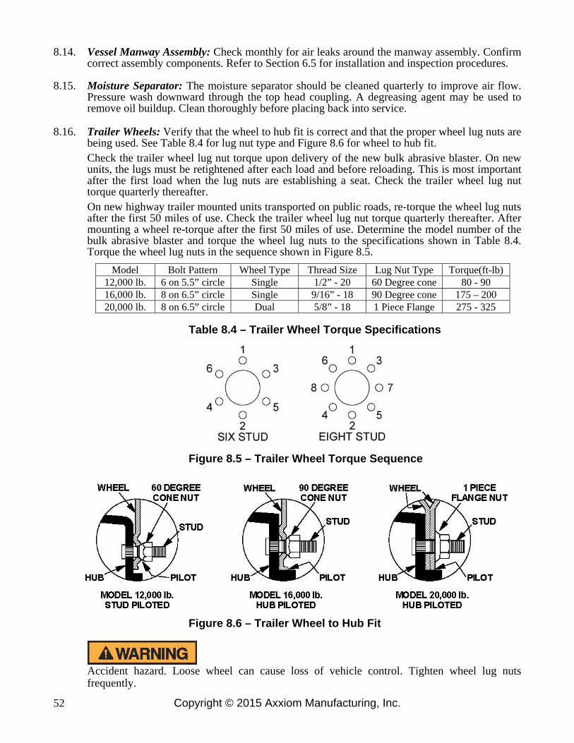
Copyright © 2015 Axxiom Manufacturing, Inc. 52
8.14. Vessel Manway Assembly: Check monthly for air leaks around the manway assembly. Confirm correct assembly components. Refer to Section 6.5 for installation and inspection procedures.
8.15. Moisture Separator: The moisture separator should be cleaned quarterly to improve air flow.
Pressure wash downward through the top head coupling. A degreasing agent may be used to remove oil buildup. Clean thoroughly before placing back into service.
8.16. Trailer Wheels: Verify that the wheel to hub fit is correct and that the proper wheel lug nuts are
being used. See Table 8.4 for lug nut type and Figure 8.6 for wheel to hub fit. Check the trailer wheel lug nut torque upon delivery of the new bulk abrasive blaster. On new units, the lugs must be retightened after each load and before reloading. This is most important after the first load when the lug nuts are establishing a seat. Check the trailer wheel lug nut torque quarterly thereafter. On new highway trailer mounted units transported on public roads, re-torque the wheel lug nuts after the first 50 miles of use. Check the trailer wheel lug nut torque quarterly thereafter. After mounting a wheel re-torque after the first 50 miles of use. Determine the model number of the bulk abrasive blaster and torque the wheel lug nuts to the specifications shown in Table 8.4. Torque the wheel lug nuts in the sequence shown in Figure 8.5.
Model Bolt Pattern Wheel Type Thread Size Lug Nut Type Torque(ft-lb)
12,000 lb. 6 on 5.5” circle Single 1/2” - 20 60 Degree cone 80 - 90 16,000 lb. 8 on 6.5” circle Single 9/16” - 18 90 Degree cone 175 – 200 20,000 lb. 8 on 6.5” circle Dual 5/8” - 18 1 Piece Flange 275 - 325
Table 8.4 – Trailer Wheel Torque Specifications
Figure 8.5 – Trailer Wheel Torque Sequence
Figure 8.6 – Trailer Wheel to Hub Fit
Accident hazard. Loose wheel can cause loss of vehicle control. Tighten wheel lug nuts frequently.

Copyright © 2015 Axxiom Manufacturing, Inc. 53
8.17. Vessel Mount Bolts: Check the vessel to trailer mounting bolt torque upon delivery of the new bulk abrasive blaster. Re-torque the mounting bolts after the first 50 miles of use. Check the mounting bolt torque quarterly thereafter. Torque the vessel to trailer mounting bolts to 98 ft lb. See the drawing in Section 9.3(a).
8.18. Trailer Axle Maintenance: (yearly hub/drum inspection and removal) 8.18.1. Removal of Hub
(1) Remove wheel. (2) Remove dust cap. (3) Remove cotter pin. (4) Unscrew the spindle nut counter-clockwise. (5) Remove spindle washer. (6) Remove hub/drum from spindle. (7) Inspect hub/drum for abnormal wear or scoring. Replace if needed.
8.18.2. Seal Replacement (1) Seal should be replaced each time the hub is removed. (2) Pry the seal out of the hub with a screwdriver.
(3) Tap new seal into place.
8.18.3. Bearing Maintenance, Adjustments, and Replacements.
(1) Inspect for corrosion and wear. (2) If any rust or wear exists on the bearing remove and replace it. (3) If bearings are found to be in good condition, then cleaning and repacking the grease is all that is
needed. Note: Do not spin bearings with compressed air. (4) Hand pack each bearing individually using a premium water resistant wheel bearing grease.
(5) Reinstall the hub, reversing the procedure above then adjust bearings per procedures below. 8.18.4. Bearing Adjustment
(1) Recommended Setting: The typical trailer hub uses a hardened washer and slotted hex nut for bearing adjustment. Hubs are usually set with a free running clearance or endplay of 0.001” to 0.010”. The use of a dial indicator is the only satisfactory method of checking adjustment.
(2) Feel and drag method: Tighten the slotted nut until the hub drags slightly when rotated (Rotating
the hub while tightening the nut seats the bearing.). Loosen the slotted nut 1/6th turn (1 Hex) to align nut slot with the cotter pin hole. Wheel should turn freely. Insert new cotter pin through nut and spindle. If necessary loosen, never tighten, nut to align the slot with the hole in the spindle. Bend one leg of the cotter pin over the end of the spindle and the other leg over the nut. Tap legs slightly to set. Cotter pin must be tight.
(3) Torque Wrench Method: Make sure nut is loose. Tighten nut with torque wrench to an initial torque
of 50 ft-lb. Loosen nut from initial torque and finger tighten. Insert new cotter pin through nut and spindle. If necessary loosen, never tighten, nut to align slot with the hole in the spindle. Bend one leg of cotter pin over the end of the spindle and the other leg over the nut. Tap legs slightly to set. Cotter pin must be tight.
(4) Perform Dial Indicator Test: Attach dial indicator block to the wheel. With both hands, push the
wheel towards the trailer. Set the sensory tip of the dial indicator against the outer edge of the spindle. Set the dial indicator to zero. Grasp the tire at the top and the bottom and gently pull out. Check the reading on the dial indicator for the amount of endplay present in the bearing. (0.001” to 0.010”) Readjust the bearing if required.
8.19. Trailer Components:
Remaining trailer components must be inspected and repaired as needed by a qualified service mechanic. See the maintenance schedule for in Section 8.20 for required inspection intervals.

Copyright © 2015 Axxiom Manufacturing, Inc. 54
8.20 Maintenance Schedules Quick Reference Charts Note: The following are minimum requirements for inspection and maintenance; however, the equipment should be inspected and serviced immediately if abnormal operation is detected.
BULK ABRASIVE BLASTER MAINTENANCE SCHEDULE
Item Function Required Daily Weekly Monthly Quarterly
Blaster Vessel
Hydrostatic Test See Section 8.1
As required by state law and/or local authorities
Blaster Vessel
Check for exterior damage (corrosion, dents, bulges)
See Section 8.2 X
Blaster Vessel
Check for interior wear, corrosion, & pitting. Check Y-strainer or GSV, & piping
See Section 8.3 X
Closure Check component operation and condition. See
Section 8.4 Before every use
Closure Check camlock nut torque
See Section 8.5 X
Blast & Air Hoses
Check air & blast hoses for soft spots, wear, cracks, or air leaks
See Section 8.6 X
Remote Control Hoses
Check control air hoses for soft spots, wear, cracks, or air leaks
See Section 8.6 X
Blaster Piping &
Pipe Fittings
Check pipe & pipe fittings for wear, cracks, or air leaks
See Section 8.6 X
Remote Control Wires
Inspect wiring for bare spots, fraying, cuts, or cracks
See Section 8.6 X
Blast & Air Hose
Couplings
Check for safety pins and whip checks See Section 8.7
X
Hose Coupling Gaskets
Check for leaks at the air, blast, & and threaded hose coupling gaskets
See Section 8.8 X
Blast Nozzle
Check blast nozzle threads and jacket for wear, damage, or air leaks.
See Section 8.9 X
Valves Disassemble, inspect, and lubricate.
Check for proper operation. See Section 8.10
X
Blowdown Ball Valve
Check for proper opening and closing. Check for wear, damage, or air leaks.
See Section 8.11 Before every use
Personal Protective Equipment
Check for presence and condition of all personal protective equipment.
See Section 3.10 and 8.12 X
Warning Decals
Check for presence and condition of all warning decals
See Section 0.0 and 8.13 X
Vessel Manway
Check gasket for wear, cracking, or dry rotting. Check sealing surfaces for damage.
See Sections 6.5 and 8.14. X
Moisture Separator
Degrease internal demister element. See Section 8.15.
X
Vessel Mount Bolts
Tighten to specified torque. See Section 8.17.
X

Copyright © 2015 Axxiom Manufacturing, Inc. 55
BULK TRAILER MAINTENANCE SCHEDULE
Item Function Required 3 Months
Or 3,000 miles
6 Months Or
6,000 miles
12 Months Or
12,000 miles
Brakes Test that they are
operational Before every use
Brake Adjustment
Adjust to proper operating clearance
X
Brake Magnets
Inspect for wear and current draw
X
Brake Linings Inspect for wear and
contamination X
Brake Controller
Check for amperage and modulation
X
Brake Cylinders
Check for fluid leaks, or sticking
X
Brake Lines Inspect for cracks, fluid
leaks, or kinks X
Trailer Brake Wiring
Inspect wiring for bare spots, fraying, etc.
X
Breakaway Systems
Check battery charge and switch operation
Before every use
Hub/Drum Check for abnormal wear
or scoring See Section 8.18
X
Wheel Bearings &
Cups
Inspect for corrosion or wear; clean and repack
See Section 8.18 X
Seals Inspect for oil leakage;
replaced if removed See Section 8.18
X
Springs Inspect for wear or
loss of arch X
Suspension Parts
Inspect for bending, loose fasteners, wear
X
Hangers Inspect welds X
Wheel Nuts & Bolts
Tighten to specified torque values
See Section 8.16 X
Wheels Inspect for cracks, dents,
or distortion X
Tire Inflation Pressure
Inflate tires to manufacturer specifications
Before every use
Tire Condition
Inspect for cuts, wear, bulging, etc.
X

Copyright © 2015 Axxiom Manufacturing, Inc. 56
Figure 8.7 – Typical Bulk Abrasive Blaster

Copyright © 2015 Axxiom Manufacturing, Inc. 57
The following pages contain drawings representing typical
blast control systems and components. Determine the type
of control system the abrasive blast system is equipped with
(pneumatic or electric controls), then reference the
appropriate drawing and parts list to determine the
required parts. To insure the proper operation of the blast
system only use Schmidt® original factory replacement
parts furnished by an authorized Schmidt distributor. See
Section 1.39 and Section 12.2.12.
9.0 Drawings and Parts Lists

Copyright © 2015 Axxiom Manufacturing, Inc. 58
9.1(a) Bulk Abrasive Blaster with Pneumatic Control System

Copyright © 2015 Axxiom Manufacturing, Inc. 59
9.1(b) Pneumatic Control System Parts List

Copyright © 2015 Axxiom Manufacturing, Inc. 60
9.2(a) Bulk Abrasive Blaster with Electric Control System
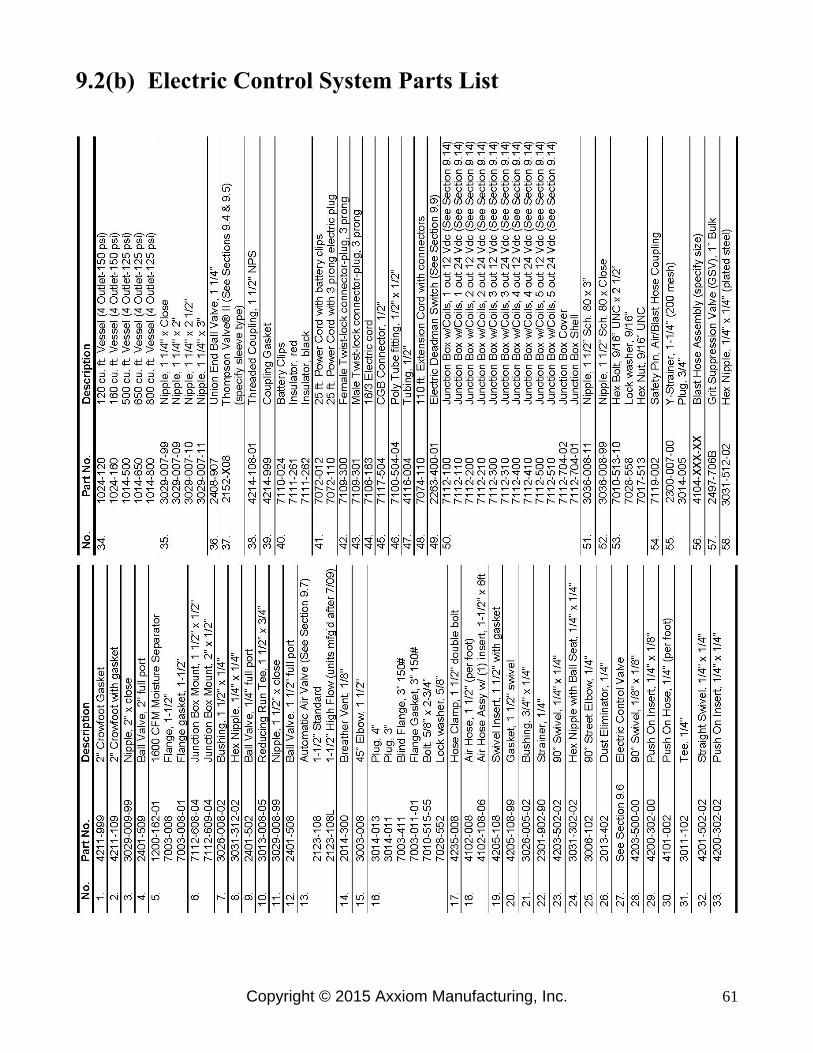
Copyright © 2015 Axxiom Manufacturing, Inc. 61
9.2(b) Electric Control System Parts List

Copyright © 2015 Axxiom Manufacturing, Inc. 62
9.3(a) Vessel and Trailer Assembly

Copyright © 2015 Axxiom Manufacturing, Inc. 63
9.3(b) Vessel and Trailer Parts List

Copyright © 2015 Axxiom Manufacturing, Inc. 64
9.4 Thompson Valve®

Copyright © 2015 Axxiom Manufacturing, Inc. 65
9.5 Thompson Valve® II

Copyright © 2015 Axxiom Manufacturing, Inc. 66
9.6 Control Valves (pneumatic and electric)

Copyright © 2015 Axxiom Manufacturing, Inc. 67
9.7 Automatic Air Valve (normally closed)
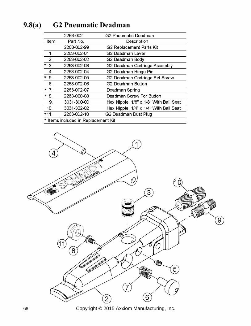
Copyright © 2015 Axxiom Manufacturing, Inc. 68
9.8(a) G2 Pneumatic Deadman

Copyright © 2015 Axxiom Manufacturing, Inc. 69
9.8(b) Deadman Valves (Pneumatic)

Copyright © 2015 Axxiom Manufacturing, Inc. 70
9.9 Deadman Switches (Electric)
*Electric shock hazard. To minimize shock hazard use electric deadman in low voltage applications only (12-24 volts).
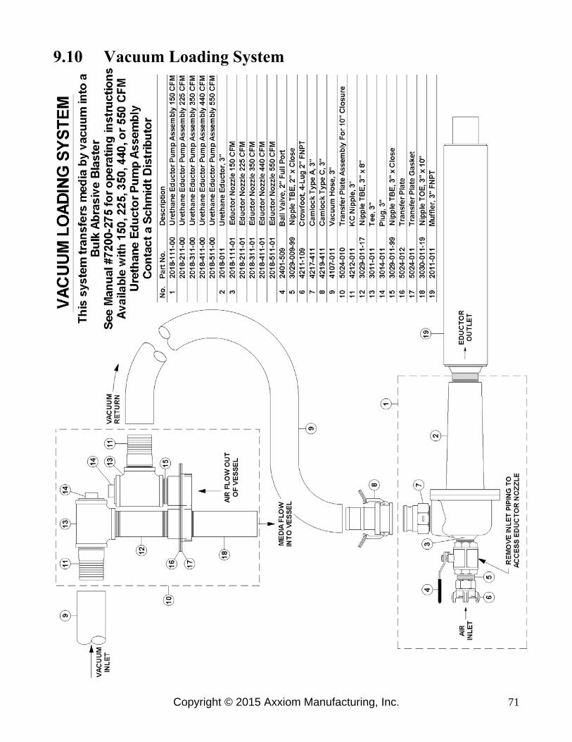
Copyright © 2015 Axxiom Manufacturing, Inc. 71
9.10 Vacuum Loading System

Copyright © 2015 Axxiom Manufacturing, Inc. 72
9.11 Remote Abrasive Cut-off (Pneumatic)

Copyright © 2015 Axxiom Manufacturing, Inc. 73
9.12 Remote Abrasive Cut-off (Electric)

Copyright © 2015 Axxiom Manufacturing, Inc. 74
9.13 Halok® Assembly

Copyright © 2015 Axxiom Manufacturing, Inc. 75
9.14 Electric Schematic
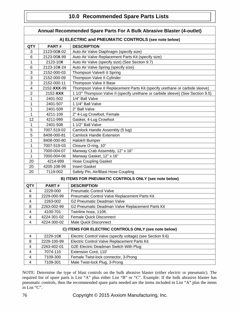
Copyright © 2015 Axxiom Manufacturing, Inc. 76
Annual Recommended Spare Parts For A Bulk Abrasive Blaster (4-outlet)
A) ELECTRIC and PNEUMATIC CONTROLS (see note below)
QTY PART # DESCRIPTION 3 2123-00X-02 Auto Air Valve Diaphragm (specify size) 6 2123-00X-99 Auto Air Valve Replacement Parts Kit (specify size) 1 2123-10X Auto Air Valve (specify size) (See Section 9.7) 6 2123-10X-24 Auto Air Valve Spring (specify size) 3 2152-000-03 Thompson Valve® II Spring 3 2152-000-09 Thompson Valve II Cylinder 3 2152-000-11 Thompson Valve II Base 4 2152-XXX-99 Thompson Valve II Replacement Parts Kit (specify urethane or carbide sleeve) 2 2152-XXX 1 1/2" Thompson Valve II (specify urethane or carbide sleeve) (See Section 9.5) 1 2401-502 1/4" Ball Valve 1 2401-507 1 1/4" Ball Valve 1 2401-509 2" Ball Valve 1 4211-109 2" 4-Lug Crowfoot, Female 12 4211-999 Gasket, 4-Lug Crowfoot 1 2401-508 1 1/2" Ball Valve 5 7007-519-02 Camlock Handle Assembly (5 lug) 5 8408-000-81 Camlock Handle Extension 1 8408-000-80 Halok® Bumper 1 7007-519-03 Closure O-ring, 10" 1 7000-004-07 Manway Crab Assembly, 12" x 16" 1 7000-004-06 Manway Gasket, 12” x 16” 20 4214-999 Hose Coupling Gasket 20 4205-108-99 Insert Gasket 20 7119-002 Safety Pin, Air/Blast Hose Coupling
B) ITEMS FOR PNEUMATIC CONTROLS ONLY (see note below)
QTY PART # DESCRIPTION 4 2229-000 Pneumatic Control Valve 8 2229-000-99 Pneumatic Control Valve Replacement Parts Kit 4 2263-002 G2 Pneumatic Deadman Valve 8 2263-002-99 G2 Pneumatic Deadman Valve Replacement Parts Kit 4 4100-701 Twinline hose, 110ft. 4 4224-301-02 Female Quick Disconnect 4 4224-300-02 Male Quick Disconnect
C) ITEMS FOR ELECTRIC CONTROLS ONLY (see note below)
4 2229-10X Electric Control Valve (specify voltage) (see Section 9.6) 8 2229-100-99 Electric Control Valve Replacement Parts Kit 4 2263-402-01 G2E Electric Deadman Switch With Plug 4 7074-110 Extension Cord, 110' 4 7109-300 Female Twist-lock connector, 3-Prong 4 7109-301 Male Twist-lock Plug, 3-Prong
NOTE: Determine the type of blast controls on the bulk abrasive blaster (either electric or pneumatic). The required list of spare parts is List “A” plus either List “B” or “C”. Example: If the bulk abrasive blaster has pneumatic controls, then the recommended spare parts needed are the items included in List “A” plus the items in List “C”.
10.0 Recommended Spare Parts Lists

Copyright © 2015 Axxiom Manufacturing, Inc. 77
This section lists probable causes of problems that may occur during operation of the abrasive blaster. Not all of the “probable causes” may apply to each particular abrasive blaster. The probable cause may not apply because of the control type and accessories on the abrasive blaster. Refer to Figure 11.1 or Figure 8.7 and the drawings in Section 9.0.
The bulk abrasive blaster is a Pressurized Vessel. Propelled objects will cause serious injury or death. Depressurize vessel before performing any maintenance. See Section 6.2. 11.1 Malfunction With Deadman Lever In The “Off” Position
11.1.1. Blast air stops but abrasive will not shut off (1) Trash stuck between plunger and seat in Thompson Valve® (#13).
(2) Defective valve plunger in Thompson Valve (#13). (3) Defective sleeve in Thompson Valve (#13). (4) Blocked signal air hose to Thompson Valve (#13). (5) Defective spring in Thompson Valve (#13) (check length of spring). (6) Thompson Valve cap (or spring retainer) not screwed all the way down (hand tighten only).
11.1.2. Abrasive stops but blast air will not shut off (1) Defective spring in automatic air valve (#10).
(2) Defective seat in automatic air valve (#10). (3) Blocked air hose to automatic air valve (#10). (4) Defective o-ring in automatic air valve (#10) (around shaft).
11.1.3. Both blast air and abrasive will not shut off
(1) Control lines to deadman valve (#1) are crossed. (2) Non-Schmidt deadman (#1) has been installed. (3) Control valve (#12) stuck in the “ON” position. (4) Blocked control lines.
(5) Defective deadman valve (#1). Pneumatic deadman cartridge plunger stuck in the “ON” position (down). Cartridge plunger is visible below deadman handle.
11.1.4. Blast outlet turns on accidentally
(1) The deadman lever (#1) is worn out. (2) The safety button on the deadman is missing. See drawings in Section 9.8 and 9.9. (3) A bleeder type deadman valve has been installed. A bleeder type deadman valve is not safe
because a particle of dirt from the air hose can plug the bleed hole and cause the blast outlet to turn on. See Warnings and Rules for Safer Operation in Section 1.0.
(4) Defective electric deadman switch or electric wiring (check for an electric short).
11.0 Troubleshooting

Copyright © 2015 Axxiom Manufacturing, Inc. 78
Figure 11.1 – Typical Bulk Abrasive Blaster
11.2 Malfunction With Deadman Lever In The “On” Position
11.2.1. Air blasts with no abrasive (1) Check abrasive level in the blast vessel even if one outlet continues to blast normally.
(2) Blocked control hose to Thompson Valve® (#13). (3) Thompson Valve plunger stuck in closed position. (4) Trash plugging opening from tank to Thompson Valve (#13). See Section 11.3. (5) Insufficient air pressure to open Thompson Valve (fully open requires 80 psig). (6) Abrasive flow problems. See Section 11.3. (7) Defective Thompson Valve piston seal (air will leak from breather).
11.2.2. Abrasive choking out of blast hose with low blast air pressure. (1) Thompson Valve abrasive adjustment knob (#20) is open too far.
(2) Control hose to automatic air valve (#10) is blocked. (3) Choke valve (#9) is partially closed.
(4) Low air compressor output cfm (unit may cycle on and off). See Section 3.0. (5) Blocked automatic air valve (#10) breather vent prevents full opening.
11.2.3. Reduced Pressure At The Nozzle (with or without abrasive flow)
(1) Low air compressor output cfm. See Section 3.0 for air requirements. (2) Air hose too small. (3) Thompson Valve abrasive adjustment knob (#20) is open too far. (4) Check for leaks in blast vessel or control piping. (5) Choke valve (#9) is partially closed. (6) Trash may be partially plugging the nozzle orifice (#21). (7) Blocked automatic air valve (#10) breather vent prevents full opening.

Copyright © 2015 Axxiom Manufacturing, Inc. 79
11.2.4. Blast is slow to turn on or will not turn on when deadman lever is pressed down. (1) Check quick couplings (#17) on control hoses to see if they are connected properly. (2) Control valve (#12) stuck in exhaust position or midway (air will leak from breather (#11)). (3) 1/4" strainer (#3) blocked. (4) Control hoses blocked. (5) Cartridge in deadman valve (#1) is blocked. (6) Low air compressor output cfm (unit may cycle on and off). See Section 3.0. (7) Air leaks in control hose from the deadman valve (#1) to control valve (#12). (8) Trash blocking nozzle orifice.
(9) Blocked automatic air valve (#10) breather vent prevents full opening.
11.3 Notes on Abrasive Flow Problems
11.3.1. Thompson Valve® operation
If abrasive flow is a problem, remember; the Thompson Valve only opens and closes. The total travel to full open is approximately 3/4 of an inch. This can be quickly checked with the adjustment knob on the abrasive valve. For this procedure manually close the choke valve (#9) and the abrasive shutoff valve (#24) to stop blast flow. This test is to verify that the Thompson Valve is opening. With the deadman off, screw the Thompson Valve knob down until it stops. Notice that the knob turns easily when the deadman is off. Next, back the knob out 3/4 of an inch or slightly less, then press the deadman lever down to open the Thompson Valve. The knob should get tight or more difficult to turn because the valve has opened against the adjustment. This guarantees that the valve is fully open. If the material will not flow with the valve fully open, there is an abrasive flow problem, not a problem with the Thompson Valve. The abrasive may be wet, or there may be trash blocking the opening. Try choking the blast outlet to clear the opening. Proceed to step 11.3.2. If the knob does not get tighter during this test troubleshoot the controls and the Thompson Valve piston seal.
Do Not hammer on any part of the pressure vessel to improve abrasive flow. This will cause cracks that may lead to pressure vessel rupture.
11.3.2. Choking the blast outlet
The choke valve (#9) is used to clear any trash that may get into the blast vessel and block the Thompson Valve orifice. Whenever trash (paint chip, cigarette butt, etc.) blocks the Thompson Valve orifice, the procedure is to fully open the Thompson Valve knob, then press down the deadman lever (#1) to begin blasting. While blasting, have an assistant close the choke valve completely for about one second. This creates differential pressure at the Thompson Valve (high pressure above; low pressure below). The higher pressure from the blast vessel should be enough to loosen the trash blocking the Thompson Valve orifice and blast it through the blast nozzle (#21). To minimize chance of excess wear of the Thompson Valve keep the choke valve fully open during normal blasting. If the blaster is equipped with the abrasive cut-off feature set the valve (or switch) to the on-position for the choke procedure. See Sections 9.11 and 9.12. Note: The Thompson Valve II has a cleanout port to use for this procedure. See the Thompson Valve II drawing in Section 9.5 (Item 27).
11.3.3. Blast control hoses
Remember, the blaster controls and valves are normally closed. Therefore, the control hoses are depressurized to turn the blast off and pressurized to turn the blast on. If a needle gauge is available, it is the quickest way to check to see if there is pressure or not. If no needle gauge is available, disconnect each control hose fitting one at a time until the problem is located.

Copyright © 2015 Axxiom Manufacturing, Inc. 80
11.4 Troubleshooting Trailer Hydraulic Brakes
11.4.1. Dragging Brakes
(1) Check brake adjustment. (2) Check for faulty master cylinder. (3) Check for improperly installed backing plate. (4) Check for corroded brake assembly. (5) Improper weight on trailer tongue.
11.4.2. Noisy Brakes (1) Check brake adjustment. (2) Check for worn brake shoes. (3) Check for contaminated brake linings. (4) Check for loose parts in drum. (5) Check for bent backing plate. (6) Check wheel bearing adjustment. (7) Check for damaged wheel bearing.
11.4.3. Locking Brakes
(1) Check for improper brake adjustment. (2) Check for broken or loose brake parts. (3) Check for damaged or out of round brake drums.
11.4.4. No Brakes
(1) Low brake fluid level. (2) Broken brake line. (3) Loose brake line connection. (4) Air in the brake lines. (5) Master cylinder not working. (6) Excessive weight on tow bar.
11.4.5. Weak Brakes
(1) Trailer is overloaded. (2) Not enough brakes on trailer. (3) Improper brake adjustment. (4) Corroded brake parts. (5) Worn brake cylinder. (6) Incorrect brake shoe or lining. (7) Lining is glazed. (8) Grease on lining. (9) Worn out brake drum(s).
(10) Air in brake lines. (11) Brakes are overheated.
11.4.6. Surging Brakes
(1) Brake drum(s) are damaged or out of round. (2) Shoe linings have grease or oil on them.

Copyright © 2015 Axxiom Manufacturing, Inc. 81
11.4.7. Swaying of Trailer When Braking
(1) Incorrect brake adjustment. (2) Incorrect tire air pressure. (3) Different tire sizes on axle. (4) Shoe or lining not properly operating. (5) Brake lines damaged
11.4.8. Brake Adjustment Procedure (1) Jack up trailer and support with jack stands. (2) The brake adjustment nut is located behind a slot at the bottom of the backing plate.
Tighten until the wheel cannot be rotated by hand. Note: always rotate wheel in direction of forward rotation only.
(3) Back off the adjustment nut seven to ten notches. (4) Remove jack stands from trailer support.
11.4.9. Brake System Bleeding Procedure
(1) Only use new hydraulic brake fluid. DOT-3 heavy duty fluid is recommended. (2) Fill the master cylinder with fluid. Install bleeder hose on first wheel cylinder to be bled. If
tandem trailer, bleed rear axle first. Have loose end of the hose submerged in brake fluid in glass container to observe bubbling.
(3) Loosen the wheel cylinder bleeder screw one turn. This will open the system to the atmosphere due to the passage drilled through the bleeder screw. Push the actuator with long steady strokes. The bleeding operation is complete when bubbles no longer rise to the surface of the fluid. Be sure to close the bleeder screw securely.
(4) Repeat bleeding operation at each wheel cylinder. During the bleeding process, refill the brake fluid so the level does not fall below the full level in the master cylinder reservoir.
(5) After bleeding is completed, make sure master cylinder is filled to 3/8” below the top of the reservoir and filler cap is installed.

Copyright © 2015 Axxiom Manufacturing, Inc. 82
11.5 Troubleshooting Trailer Electric Brake
11.5.1. Dragging Brakes
(1) Check brake adjustment. (2) Check for defective controller. (3) Check for improperly installed backing plate. (4) Check for corroded brake assembly. (5) Check for weak or broken brake shoe return spring. (6) Check for worn or damaged lever arm between magnet and brake shoe. (7) Check for correct controller position.
11.5.2. Noisy Brakes
(1) Check brake adjustment. (2) Check for worn brake shoes. (3) Check for contaminated brake linings. (4) Check for weak or broken brake shoe return springs. (5) Check for bent backing plate. (6) Check for improperly installed backing plate. (7) Check wheel bearings adjustment. (8) Check for worn or damaged wheel bearings. (9) Check for worn of damaged magnets.
11.5.3. Brakes Locked and Brake Pedals Not Depressed
(1) Check stoplight switch adjustment. (2) Check for short between stoplight switch circuit and power supply circuit. (3) If brakes are locked when 4-way flashers are operated, check for pulse preventor installed
in circuit.
11.5.4. LED Light Comes On Dim & Gets Brighter as Brakes Applied
(1) If trailer is connected, this indicates normal operation. (2) If trailer is not connected, check for short in electro-magnet circuit between controller and
trailer connector at rear of vehicle.
11.5.5. LED Light Comes On Bright & Stays Bright
(1) If trailer is hooked up, this indicates system is not operating. Check trailer brakes and all connecting wiring.
(2) If trailer is not connected, this indicates that system is ready to function.
11.5.6. Inoperative Breakaway Switch
(1) Check for dead or weak trailer 12-volt battery. (2) Check all wiring and connections. (3) Check breakaway switch (4) If only one brake is operating, check other magnets.
11.5.7. Uneven Tire Wear
On tandem axle trailers, check voltage at front axle and rear axle with brakes applied. At times, the front axle will “lift” allowing front wheel to lock and slide. Correction can be made by installing a resistor in front brake circuit or combination of axle resistor and an adjusted controller.

Copyright © 2015 Axxiom Manufacturing, Inc. 83
11.5.8. No Brakes
(1) Check for defective circuit breakers. (2) Check for open or shorted circuit. (3) Check for properly wired system, including ground between towing vehicle and trailer. (4) Check for defective controller or loose wiring at controller. (5) Check brake adjustment. (6) Check for defective resistor or loose wiring at resistor. (7) Check for worn or defective magnet(s). (8) Check for a damaged or worn connector between towing vehicle/trailer. (9) Check for a burned out resistor. (10) Check that correct controller is installed
11.5.9. Intermittent or Surging Brakes
(1) Check for out-of-round brake drums. (2) Check for properly wired system, including ground between towing vehicle and trailer. (3) Check for defective magnet or wiring (4) Check for loose/worn wheel bearings.
11.5.10. Ineffective or Weak Brakes
(1) Check that trailer is not overloaded (see Section 2.0). (2) Check for loose or corroded connections. (3) Check for properly wired system. (4) Check for a shorted circuit. (5) Check variable resistor for correct resistance to trailer. (6) Check for worn or defective magnet. (7) Check brake adjustment. (8) Check for bent backing plate. (9) Check for contaminated brake linings. (10) Check brake system wiring. (11) Check for worn, damaged brake linings. (12) Check for weak or broken brake shoe return springs. (13) Check for defective or worn brake drums. (14) Check for loose axle. (15) Check that correct controller is installed. (16) Check for correct controller position.
11.5.11. Grabbing or Locking Brakes
(1) Check for improperly installed backing plate. (2) Check for contaminated brake linings. (3) Check for weak or broken brake shoe return springs. (4) Check for out-of-round brake drums. (5) Check variable resistor. (6) Check that a variable resistor is installed (if necessary). (7) Check that correct controller is installed. (8) Check for defective controller. (9) Check for rust on armature plate or brake drum. (10) Check for loose/worn wheel bearings. (11) Check for correct controller position.

Copyright © 2015 Axxiom Manufacturing, Inc. 84
12.1 Warranty
This following section is to be used as a guide in determining warranty policies and procedures for SCHMIDT® products. It is to be used in determining whether a warranty is justified and as a procedural guide in completing a SCHMIDT warranty claim.
12.2 Warranty Policy
1. All SCHMIDT products are guaranteed to be free of defects in material and workmanship at time of shipment. Axxiom Manufacturing, Inc. warrants its products against defects in material and workmanship under normal and proper use for a period of ninety (90) days from the date of delivery. Such warranty is extended only to the buyer who purchases the equipment directly from Axxiom Manufacturing, Inc. or its authorized distributors. This warranty does not include expendable parts such as, but not limited to, hoses, nozzles, and seals.
2. The obligation under this warranty is strictly limited to the replacement or repair, at
Axxiom’s option, of machines and does not include the cost of transportation, loss of operating time, or normal maintenance services. Axxiom Manufacturing, Inc. shall have no liability for labor, consequential damages, freight or special charges.
3. This warranty does not apply to failure occurring due to abuse, misuse, negligence,
corrosion, erosion, normal wear and tear, alterations or modifications made to the machine without express written consent of Axxiom Manufacturing, Inc.
4. Warranty requests must be submitted in writing within thirty (30) days after failure. 5. Written authorization to return merchandise under warranty must first be obtained from
Axxiom Manufacturing, Inc. In no case is merchandise to be returned to Axxiom for credit without authorization. At the time of authorization, Axxiom will issue a return authorization number that must be included on all packages and correspondence. Any material returned without prior authorization will remain the property of the sender and Axxiom will not be responsible for it.
6. All returns must be shipped prepaid freight. All returns may be exchanged for other
equipment or parts of equal dollar value. If goods are not exchanged, they are subject to a 20% restocking charge. Any cost incurred by Axxiom Manufacturing, Inc. to restore such goods to first class condition will be charged to the customer.
7. Axxiom Manufacturing, Inc. reserves the right to inspect and make the final decision on any
merchandise returned under warranty.
8. Axxiom Manufacturing, Inc. offers no warranty with respect to accessories, including but not limited to, engines, motors, batteries, tires and any other parts not manufactured by Axxiom Manufacturing, Inc., but which the original manufacturer warrants.
12.0 Warranty and Reference Information

Copyright © 2015 Axxiom Manufacturing, Inc. 85
9. Axxiom Manufacturing, Inc. reserves the right to make product changes or improvements without prior notice and without imposing any obligation upon itself to install the same on its products previously sold.
10. The above warranty conditions can only be altered by Axxiom Manufacturing, Inc. Axxiom
must confirm alterations in writing for each specific transaction.
11. Axxiom Manufacturing, Inc. reserves the right to establish specific warranty terms for used or demo machines on an individual transaction basis. Invoices covering such merchandise will clearly state the provisions of the applicable warranty for each specific transaction.
12. USE OF NON-ORIGINAL SCHMIDT® FACTORY REPLACEMENT PARTS ON ANY
SCHMIDT EQUIPMENT VOIDS ALL WARRANTIES.
13. AXXIOM MANUFACTURING, INC. DOES NOT AUTHORIZE ANY PERSON, REPRESENTATIVE OR SERVICE OR SALES ORGANIZATION TO MAKE ANY OTHER WARRANTY OR TO ASSUME ON BEHALF OF AXXIOM MANUFACTURING, INC. ANY LIABILITY IN CONNECTION WITH THE SALE OF OUR PRODUCTS OTHER THAN THOSE CONTAINED HEREIN.
14. UNDER NO CIRCUMSTANCES SHALL AXXIOM MANUFACTURING, INC. BE
LIABLE TO CUSTOMER OR ANY OTHER PERSON FOR ANY DIRECT, INCIDENTAL, OR CONSEQUENTIAL DAMAGES RESULTING FROM THE USE OF THE PRODUCT OR ARISING OUT OF ANY BREACH OF ANY WARRANTY OR FOR ANY SPECIAL OR CONSEQUENTIAL DAMAGES OF ANY CHARACTER, INCLUDING WITHOUT LIMITATIONS, DAMAGES FOR ANY LOSS OF GOODWILL, WORK STOPPAGE, OR ANY AND ALL OTHER COMMERCIAL DAMAGES OR LOSSES.
15. AXXIOM MANUFACTURING, INC. MAKES NO OTHER WARRANTIES,
EXPRESSED OR IMPLIED, INCLUDING, BUT NOT LIMITED TO, THE IMPLIED WARRANTIES OF MERCHANTABILITY AND FITNESS FOR A PARTICULAR PURPOSE WITH RESPECT TO THE SCHMIDT PRODUCTS SOLD PURSUANT THERETO.
12.3 Trademarks, Patents, and Proprietary Statements
Schmidt, the Schmidt S logo, Thompson Valve, Combo Valve, and Halok are registered trademarks owned by Axxiom Manufacturing, Inc. Use of the Schmidt, the Schmidt S logo, Thompson Valve, and Combo Valve trademarks without the written consent of Axxiom Manufacturing is strictly prohibited. Products manufactured and marketed by Axxiom Manufacturing, Inc. are protected by patents issued or pending in the United States and other countries. The text, diagrams, and drawings contained in this manual are proprietary information intended solely for instruction in the operation of the specified equipment. Use of any text, diagrams, or drawings contained in this manual for any reason other than its intended purpose without the written consent of Axxiom Manufacturing, Inc. is strictly prohibited.

Copyright © 2015 Axxiom Manufacturing, Inc. 86
12.4 Safety Information Sources
Axxiom Manufacturing, Inc This equipment and all Schmidt® equipment are manufactured exclusively by Axxiom Manufacturing, Inc. If any operational or safety related questions arise relating to this equipment contact Axxiom Manufacturing, Inc. Phone: 1-800-231-2085 Website: www.SchmidtAbrasiveBlasting.com Axxiom Manufacturing, Inc. 11927 South Highway 6 Fresno, Texas 77459 Occupational Safety and Health Administration (OSHA) establishes and enforces regulations regarding safety practices in the workplace including the abrasive blasting industry. Any questions, reporting of work related injuries, or reporting of unsafe work practices can be made to the following contact information. Answers to most any safety related questions can be found at the OSHA website shown below. Phone: 1-800-321-6742 Website: www.osha.gov
U.S. Department of Labor
Occupational Safety and Health Administration 200 Constitution Avenue Washington D.C. 20210
National Institute of Occupational Safety and Health (NIOSH) is a federal agency responsible for conducting research and recommendations for the prevention of work related injuries and sickness. Phone: 1-800-356-4674 Website: www.cdc.gov/niosh National Institute of Occupational Safety and Health Hubert H. Humphrey Bldg. 200 Independence Avenue, SW Room 715H Washington, DC 20201 American National Standards Institute (ANSI) coordinates the development and use of voluntary consensus standards including safety standards. Phone: 1-202-293-8020 Website: www.ansi.org American National Standards Institute 1819 L Street, NW 6th Floor Washington, DC 20036
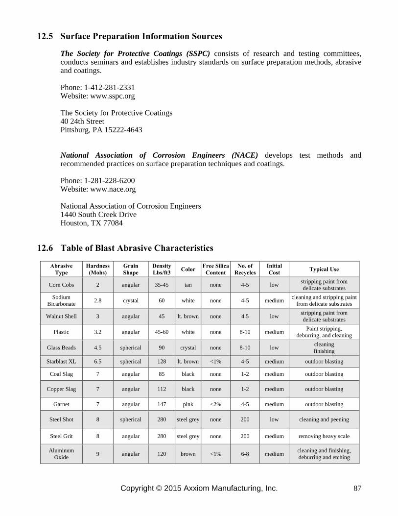
Copyright © 2015 Axxiom Manufacturing, Inc. 87
12.5 Surface Preparation Information Sources The Society for Protective Coatings (SSPC) consists of research and testing committees, conducts seminars and establishes industry standards on surface preparation methods, abrasive and coatings. Phone: 1-412-281-2331 Website: www.sspc.org The Society for Protective Coatings 40 24th Street Pittsburg, PA 15222-4643 National Association of Corrosion Engineers (NACE) develops test methods and recommended practices on surface preparation techniques and coatings. Phone: 1-281-228-6200 Website: www.nace.org National Association of Corrosion Engineers 1440 South Creek Drive Houston, TX 77084
12.6 Table of Blast Abrasive Characteristics
Abrasive Type
Hardness (Mohs)
Grain Shape
Density Lbs/ft3
Color Free Silica
Content No. of
Recycles Initial Cost
Typical Use
Corn Cobs 2 angular 35-45 tan none 4-5 low stripping paint from delicate substrates
Sodium Bicarbonate
2.8 crystal 60 white none 4-5 medium cleaning and stripping paint
from delicate substrates
Walnut Shell 3 angular 45 lt. brown none 4.5 low stripping paint from delicate substrates
Plastic 3.2 angular 45-60 white none 8-10 medium Paint stripping,
deburring, and cleaning
Glass Beads 4.5 spherical 90 crystal none 8-10 low cleaning finishing
Starblast XL 6.5 spherical 128 lt. brown <1% 4-5 medium outdoor blasting
Coal Slag 7 angular 85 black none 1-2 medium outdoor blasting
Copper Slag 7 angular 112 black none 1-2 medium outdoor blasting
Garnet 7 angular 147 pink <2% 4-5 medium outdoor blasting
Steel Shot 8 spherical 280 steel grey none 200 low cleaning and peening
Steel Grit 8 angular 280 steel grey none 200 medium removing heavy scale
Aluminum Oxide
9 angular 120 brown <1% 6-8 medium cleaning and finishing, deburring and etching

Copyright © 2015 Axxiom Manufacturing, Inc. 88
13.1 Table 1 Approximate Air Consumption (cfm) Per Blast Nozzle
NOZZLE PRESSURE
NOZZLE SIZE
60 psi
70 psi 80 psi 90 psi 100 psi
120 psi
140 psi
No.2 1/8"
14
16 18 20 22
26
30
No.3 3/16"
32
36 41 45 49
58
66
No.4 1/4"
57
65 72 80 90
105
121
No.5 5/16"
90
101 113 125 140
160
185
No.6 3/8"
126
145 163 182 200
235
270
No.7 7/16"
170
193 215 240 270
315
360
No.8 1/2"
230
260 290 320 350
410
470
No.10 5/8"
360
406 454 500 550
640
740
No.12 3/4"
518
585 652 720 790
925
1060
13.2 Table 2 Abrasive Consumption (lbs. per hour) Per Blast Nozzle
NOZZLE PRESSURE
NOZZLE SIZE
60 psi
70 psi 80 psi 90 psi 100 psi
120 psi
140 psi
No.2 1/8"
90
105 115 130 140
165
190
No 3 3/16"
205
230 260 290 320
375
430
No.4 1/4"
365
420 460 500 560
660
760
No.5 5/16"
575
650 725 825 900
1050
1200
No.6 3/8"
840
945 1050 1155 1260
1475
1700
No.7 7/16"
1150
1300 1450 1600 1750
2050
2350
No.8 1/2"
1460
1660 1850 2000 2250
2650
3000
No.10 5/8"
2290
2600 2900 3125 3520
4100
4750
No.12 3/4"
3300
3750 4180 4500 5060
5950
6800
13.3 Table 3 Hose Selection Guide (blasting @ 100 Psi)
NOZZLE SIZE
No.4 1/4" No.5 5/16" No.6 3/8" No.7 7/16"
No.8 1/2"
CFM @ 100psi
90 140 200 270
350
AIR HOSE
1 1/4" 1 1/4" 1 1/2" 1 1/2"
2"
BLAST HOSE
1" 1 1/4" 1 1/4" 1 1/2"
1 1/2"
ABRASIVE ( lbs per hr)
560 900 1260 1750
2250
13.4 Additional Information on Blasting Productivity
Air volume and pressure are very important. The blasting production rate will increase with higher blasting pressures and decrease with lower blasting pressures. The National Association of Corrosion Engineers’ data suggests that for each 1 psi reduction in nozzle pressure, there is a 1.5% production loss. Pressure drop through a Schmidt® blast unit is normally less than 1 psi, while blast units manufactured by some of our competitors have pressure losses as high as 12 psi resulting in an 18% loss of production. Air pressure loss can also be avoided by using the shortest possible hose of adequate size. The inside diameter of both the blast hose (other than whip hose) and the air hose should be approximately three times the diameter of the orifice in the blast nozzle.
Standard Schmidt blast units are rated for a maximum pressure of 150 psi. For Units manufactured prior to July 2009 150 psi was optional. Check vessel nameplate.
13.0 Blasting Data