Building Regs 2002 L1
54
PAGE CONTENTS 1 Use of Guidance 3 Summary guide to the use of this Approved Document 5 The Requirements 7 Section 0 : General 9 Performance 9 Introduction to provisions 9 Technical risk 9 Thermal conductivity and transmittance 9 U-value reference tables 10 Calculation of U-values 10 Roof window 11 Basis for calculating areas 11 Air permeability 11 Standard assessment procedure (SAP) 11 Historic buildings 11 Section 1 : Design and construction 12 Alternative methods of showing compliance 12 Elemental Method 12 U-values for construction elements 12 Heating efficiency 12 Areas for windows, doors and 13 rooflights Extensions to dwellings 13 Summary of provisions in the 13 Elemental Method Target U-value method for new 13 dwellings Optional allowance for solar gains 14 Carbon Index Method 14 Constraints when using the calculation 15 procedures Poorest acceptable U-values 15 Limiting thermal bridging at junctions and 15 around openings Limiting air leakage 15 Space heating system controls 15 Zone controls 16 Timing controls 16 Boiler control interlocks 16 Hot water systems 16 Alternative approach for space heating and HWS systems 16 PAGE Commissioning of for heating and HWS 16 systems Operating and maintenance instructions for 17 heating and HWS system controls Insulation of pipes and ducts 17 Internal lighting 17 External lighting fixed to the building 18 Conservatories 18 Section 2 : Work on existing dwellings 19 Replacement of controlled services 19 or fittings Material alterations 20 Material changes of use 20 Historic buildings 21 APPENDICES Appendix A : Tables of U-values 22 Appendix B : Calculating U-values 35 Appendix C : U-values of ground floors 41 Appendix D : Determining U-values for glazing 44 Appendix E : Target U-value examples 45 Appendix F : SAP Ratings and 48 Carbon Indexes British Standards referred to 53 Other documents referred to 54 Contents Conservation of fuel and power Approved Document L1 1 L1
description
building
Transcript of Building Regs 2002 L1

PAGE
CONTENTS 1
Use of Guidance 3
Summary guide to the use of this Approved Document 5
The Requirements 7
Section 0 : General 9
Performance 9
Introduction to provisions 9
Technical risk 9
Thermal conductivity and transmittance 9
U-value reference tables 10
Calculation of U-values 10
Roof window 11
Basis for calculating areas 11
Air permeability 11
Standard assessment procedure (SAP) 11
Historic buildings 11
Section 1 : Design and construction 12
Alternative methods of showing compliance 12
Elemental Method 12
U-values for construction elements 12
Heating efficiency 12
Areas for windows, doors and 13rooflights
Extensions to dwellings 13
Summary of provisions in the 13Elemental Method
Target U-value method for new 13dwellings
Optional allowance for solar gains 14
Carbon Index Method 14
Constraints when using the calculation 15procedures
Poorest acceptable U-values 15
Limiting thermal bridging at junctions and 15around openings
Limiting air leakage 15
Space heating system controls 15
Zone controls 16
Timing controls 16
Boiler control interlocks 16
Hot water systems 16
Alternative approach for space heating and HWS systems 16
PAGE
Commissioning of for heating and HWS 16systems
Operating and maintenance instructions for 17heating and HWS system controls
Insulation of pipes and ducts 17
Internal lighting 17
External lighting fixed to the building 18
Conservatories 18
Section 2 : Work on existing dwellings 19
Replacement of controlled services 19or fittings
Material alterations 20
Material changes of use 20
Historic buildings 21
APPENDICES
Appendix A : Tables of U-values 22
Appendix B : Calculating U-values 35
Appendix C : U-values of ground floors 41
Appendix D : Determining U-valuesfor glazing 44
Appendix E : Target U-value examples 45
Appendix F : SAP Ratings and 48Carbon Indexes
British Standards referred to 53
Other documents referred to 54
Contents
Conservation of fuel and powerApproved Document L11
L1

Approved Document L12
L1
Conservation of fuel and power

THE APPROVED DOCUMENTSThis document is one of a series that has beenapproved and issued by the Secretary of Statefor the purpose of providing practical guidancewith respect to the requirements of Schedule 1to, and regulation 7 of the Building Regulations2000 (SI 2000/2531) for England and Wales.SI 2000/2531 has been amended by the Building(Amendment) Regulations 2001 (SI 2001/3335),the Building (Amendment) Regulations 2002(SI 2002/440) and the Building (Amendment)(No. 2) Regulations 2002 (SI 2002/2871).
At the back of this document is a list of allthe documents that have been approved andissued by the Secretary of State for thispurpose.
Approved Documents are intended to provideguidance for some of the more commonbuilding situations. However, there may well bealternative ways of achieving compliance withthe requirements. Thus there is no obligationto adopt any particular solution contained inan Approved Document if you prefer to meetthe relevant requirement in some other way.
Supplementary GuidanceThe Office of the Deputy Prime Ministeroccasionally issues additional material to aidinterpretation of the guidance contained inApproved Documents. This material may beconveyed in official letters to Chief Executivesof Local Authorities and Approved Inspectorsand/or posted on the construction legislationnews page on the web site: http://www.safety.odpm.gov.uk/bregs/building.htm.
Other requirementsThe guidance contained in an ApprovedDocument relates only to the particularrequirements of the Regulations which thedocument addresses. The building work willalso have to comply with the requirements ofany other relevant paragraphs in Schedule 1 tothe Regulations.
There are Approved Documents which giveguidance on each of the Parts of Schedule 1and on regulation 7.
LIMITATION ON REQUIREMENTSIn accordance with regulation 8, therequirements in Parts A to D, F to K and N(except for paragraphs H2 and J6) of Schedule1 to the Building Regulations do not requireanything to be done except for the purpose ofsecuring reasonable standards of health andsafety for persons in or about buildings (andany others who may be affected by buildings ormatters connected with buildings). This is one
of the categories of purpose for which buildingregulations may be made.
Paragraphs H2 and J6 are excluded fromRegulation 8 because they deal directly withprevention of the contamination of water. PartsE and M (which deal, respectively, withresistance to the passage of sound, andaccess and facilities for disabled people) areexcluded from regulation 8 because theyaddress the welfare and convenience ofbuilding users. Part L is excluded fromregulation 8 because it addresses theconservation of fuel and power. All thesematters are amongst the purposes, other thanhealth and safety, that may be addressed byBuilding Regulations.
MATERIALS AND WORKMANSHIPAny building work which is subject to therequirements imposed by Schedule 1 to theBuilding Regulations should, in accordancewith regulation 7, be carried out with propermaterials and in a workmanlike manner.
You may show that you have complied withregulation 7 in a number of ways. Theseinclude the appropriate use of a productbearing CE Marking in accordance with theConstruction Products Directive (89/106/EEC) 1
as amended by the CE Marking Directive(93/68/EEC)2, or a product complying with anappropriate technical specification (as definedin those Directives), a British Standard, or analternative national technical specification ofany state which is a contracting party to theEuropean Economic Area which, in use, isequivalent, or a product covered by a nationalor European certificate issued by a EuropeanTechnical Approval issuing body, and theconditions of use are in accordance with theterms of the certificate. You will find furtherguidance in the Approved Document supportingregulation 7 on materials and workmanship.
Independent certification schemesThere are many UK product certificationschemes. Such schemes certify compliancewith the requirements of a recogniseddocument which is appropriate to the purposefor which the material is to be used. Materialswhich are not so certified may still conform toa relevant standard.
Many certification bodies which approve suchschemes are accredited by UKAS.
Conservation of fuel and powerApproved Document L13
L1
Use of guidanceTHE BUILDING REGULATIONS 2000
1 As implemented by the Construction ProductsRegulations 1991 (SI 1991/1620).
2 As implemented by the Construction Products(Amendment) Regulations 1994 (SI 1994/3051).

Approved Document L1Conservation of fuel and power4
L1 THE BUILDING REGULATIONS 2000
Technical specificationsUnder section 1(a) of the Building Act, BuildingRegulations may be made for various purposesincluding health, safety, welfare, convenience,conservation of fuel and power and preventionof contamination of water. Standards andtechnical approvals are relevant guidance tothe extent that they relate to theseconsiderations. However, they may alsoaddress other aspects of performance such asserviceability, or aspects, which although theyrelate to the purposes listed above, are notcovered by the current Regulations.
When an Approved Document makes referenceto a named standard, the relevant version ofthe standard is the one listed at the end of thepublication. However, if this version has beenrevised or updated by the issuing standardsbody, the new version may be used as a sourceof guidance provided it continues to addressthe relevant requirements of the Regulations.
The appropriate use of a product whichcomplies with a European Technical Approvalas defined in the Construction ProductsDirective will meet the relevant requirements.
The Department intends to issue periodicamendments to its Approved Documents toreflect emerging harmonised EuropeanStandards. Where a national standard is to bereplaced by a European harmonised standard,there will be a co-existence period duringwhich either standard may be referred to. Atthe end of the co-existence period the nationalstandard will be withdrawn.
THE WORKPLACE (HEALTH,SAFETY AND WELFARE)REGULATIONS 1992The Workplace (Health, Safety and Welfare)Regulations 1992 contain some requirementswhich affect building design. The mainrequirements are now covered by the BuildingRegulations, but for further information see –Workplace health, safety and welfare.Workplace (Health, Safety and Welfare)Regulations 1992. Approved Code of PracticeL24. Published by HSE Books 1992;ISBN (0 7176 0413 6).
The Workplace (Health, Safety and Welfare)Regulations 1992 apply to the common parts offlats and similar buildings if people such ascleaners and caretakers are employed to workin these common parts. Where therequirements of the Building Regulations thatare covered by this Part do not apply todwellings, the provisions may still be requiredin the situations described above in order tosatisfy the Workplace Regulations.

Conservation of fuel and powerApproved Document L15
L1SUMMARY GUIDE
Summary guide to the use of this approveddocument
Routes to compliance for new dwellings and for conservatories
STEP TEST ACTION
START Choose method of compliance
Elemental method Go to step 1
Target U-value method Go to step 5
Carbon Index method Go to step 11
Compliance by Elemental method
1 Is the heating by gas or oil boiler, heat No Elemental Method not applicable - go pump, community heating with CHP, to START and choose another methodbiogas or biomass fuel?
Yes Continue
2 For gas or oil boilers, is the SEDBUK of No Change heating system and go to step 1proposed heating system ≥ SEDBUK from Table 2 in 1.7? [Note: for heat pump, CHP, biogas or biomass fuel, efficiency is not an issue, so continue]
Yes Continue
3 Are all U-values of proposed dwelling ≤ No FAIL by Elemental Method - revisethe corresponding values from Table 1 in U-values and repeat 3 or go to START1.3?
Yes Continue
4 Is the area of windows, doors and roof windows No FAIL by Elemental Method - reduce area of ≤ 25% of total floor area? openings and repeat 4 or go to START
Yes PASS by Elemental Method and go to Additional checks
Compliance by Target U-value method
5 Calculate the target U-value (UT) from equation (1) in 1.18
6 Is the heating by a system other than gas or oil Yes Divide the target U-value (UT) by 1.15 and go boiler, heat pump, CHP, biogas or biomass fuel, or to step 8is it undecided?
No Continue
7 For gas or oil boilers, is the proposed SEDBUK for Yes Multiply the target U-value (UT) bythe heating system equal to the corresponding SEDBUK from Table 2 in 1.7?
[Note: for heat pump, CHP, Biogas or Biomass No Continuefuel, efficiency is not an issue, so continue]
8 Is there a greater area of glazing facing South than Yes Add: is facing North?
to the Target U-value (UT)
No Continue
9 Calculate the average U-value from
10 Is U ≤ UT and is the U-value of each element No FAIL by Target U-value Method - revise and go ≤ corresponding value from Table 3 in 1.29? to step 5 or go to START
Yes PASS by Target U-value method and go to Additional checks
Compliance by Carbon Index method
11 Calculate the Carbon Index (CI) as defined in SAP 2001
12 Is the Carbon Index (CI) ≥ 8.0 and is the U-value of No FAIL by Carbon Index Method - revise and go each element ≤ corresponding value from Table 3 in to step 11 or go to START1.29?
Yes PASS by Carbon Index method and go to Additional checks
∑ AU
∑ AU =
0.04 x AS – AN
AT
proposed SEDBUKSEDBUK from Table 2
U

Approved Document L1Conservation of fuel and power6
L1 SUMMARY GUIDE
Additional checks by builders
Limiting thermal bridging at junctions and around openings (see clauses 1.30 to 1.32)
Check that details comply with clauses 1.30 or that calculations show equivalence
Limiting air leakage (see clauses 1.33 to 1.35)
Check that air leakage is limited according to clauses 1.34 or 1.35
Space heating controls and HWS (see clauses 1.36 to 1.45)
Zone controls: Check that zone controls comply with clauses 1.38 and 1.39
Timing controls: Check that timing controls comply with clause 1.40
Boiler control interlocks: Check that boiler control interlocks comply with clause 1.41
Hot Water Storage: Check that hot water storage complies with clauses 1.42 to 1.45
Alternative approach for space heating and HWS systems (see clause 1.46)
Check that the space heating and hot water systems comply by adopting the relevantrecommendations in Good Practice Guide 302 and that provision has been made to include zoning,timing and interlock features similar to those given in clauses 1.36 to 1.45
Commisioning of heating and HWS systems (see clauses 1.47 to 1.49)
Inspect, commission and test systems OR check that the installation sub-contractor has certified,following commissioning, that the systems comply.
Operating and Maintenance instructions for heating and hot water systems (see clause 1.50)
Check that the building owner and/or occupier has been given information on the operation andmaintenance of the heating and hot water systems.
Insulation of pipes and ducts (see clauses 1.51 and 1.52)
Check that reasonable provision has been made to insulate pipes and ducts, and that in unheatedareas the central heating and hot water pipework has been insulated sufficiently to protect againstfreezing.
Internal Lighting (see clauses 1.53 to 1.55)
Check that reasonable provision has been made for occupiers to obtain the benefits of efficientlighting.
External lighting fixed to the building (see clause 1.56)
Check that reasonable provision has been made to enable effective control and/or use of efficientlamps.
Conservatories (see clauses 1.57 to 1.61)
When part of a new dwelling: a) Check, where the conservatory is not separated from the rest of the dwelling, that theconservatory has been treated as an integral part of the dwelling.
b) Check, where the conservatory is separated from the rest of the dwelling and has a fixed heatinginstallation, that the heating in the conservatory has its own separate temperature and on/offcontrols.
When attached to an Check, that where an opening is created or enlarged, provision has been made to limit the existing dwelling: heat loss from the dwelling such that it is no worse than before the work was undertaken.
In addition: Check, that with regard to the glazing, the safety requirements of Part N of the BuildingRegulations have been met.

Conservation of fuel and powerApproved Document L17
L1CONSERVATION OF FUEL AND POWER
OTHER CHANGES TO THEBUILDING REGULATIONS 2000Attention is particularly drawn to the followingchanges to the provisions of the BuildingRegulations 2000 made by the Building(Amendment) Regulations 2001.
Amendment to Regulation 2 -InterpretationThe definition of controlled service or fitting inRegulation 2(1) is amended to:-
“controlled service or fitting means a service orfitting in relation to which Part G, H, J or L ofSchedule 1 imposes a requirement;”.
Amendments to Regulation 3 -Meaning of building workRegulation 3(1) is amended as follows:
“3.-(1) …
(b) subject to paragraph (1A), theprovision or extension of a controlledservice or fitting in or in connection with abuilding;”
A new paragraph 3(1A) is introduced which says:
“The provision or extension of a controlledservice or fitting –
(a) in or in connection with an existingdwelling; and
(b) being a service or fitting in relation towhich paragraph L1, but not Part G, H orJ, of Schedule 1 imposes a requirement,
shall only be building work where that workconsists of the provision of a window, rooflight,roof window, door (being a door which togetherwith its frame has more than 50 per cent of itsinternal face area glazed), a space heating orhot water service boiler, or a hot water vessel.”
The Requirements
Dwellings
L1. Reasonable provision shall be made for the conservation of fueland power in dwellings by -
(a) limiting the heat loss:
(i) through the fabric of the building;
(ii) from hot water pipes and hot air ducts used for spaceheating;
(iii) from hot water vessels;
(b) providing space heating and hot water systems which are energy-efficient;
(c) providing lighting systems with appropriate lamps and sufficientcontrols so that energy can be used efficiently;
(d) providing sufficient information with the heating and hot waterservices so that building occupiers can operate and maintain theservices in such a manner as to use no more energy than isreasonable in the circumstances.
Requirement Limits on application
The requirement for sufficient controls inrequirement L1(c) applies only to externallighting systems fixed to the building.
CONSERVATION OF FUELAND POWER THE REQUIREMENT L1This Approved Document, which takes effecton 1 April 2002, deals with the followingRequirements which are contained in theBuilding Regulations 2000 (as amended bySI 2001/3335).

New Regulation 18 -Testing of building workA new Regulation 18 is substituted whichsays:-
“Testing of building work
The local authority may make such tests ofany building work as may be necessary toestablish whether it complies with regulation7 or any of the applicable requirementscontained in Schedule 1.”
Approved Document L1Conservation of fuel and power8
L1 CONSERVATION OF FUEL AND POWER

Performance0.1 In the Secretary of State's viewrequirement L1 (a) will be met by the provisionof energy efficiency measures which:
a) limit the heat loss through the roof, wall,floor, windows and doors etc by suitable meansof insulation, and where appropriate permit thebenefits of solar heat gains and more efficientheating systems to be taken into account; and
b) limit unnecessary ventilation heat loss byproviding building fabric which is reasonablyairtight; and
c) limit the heat loss from hot water pipesand hot air ducts used for space heating andfrom hot water vessels and their primary andsecondary hot water connections by applyingsuitable thicknesses of insulation where suchheat does not make an efficient contribution tothe space heating.
0.2 In the Secretary of State's viewrequirement L1 (b) will be met by the provisionof space heating and hot water systems withreasonably efficient equipment such as heatingappliances and hot water vessels whererelevant, and suitable timing and temperaturecontrols that have been appropriatelycommissioned such that the heating and hotwater systems can be operated effectively asregards the conservation of fuel and power.
0.3 In the Secretary of State's viewrequirement L1 (c) will be met by the provisionof lighting systems that utilise energy-efficientlamps where this is appropriate; and that havemanual switching controls or, in the case ofexternal lighting fixed to the building,automatic switching, or both manual andautomatic switching controls as appropriate,such that the lighting systems can be operatedeffectively as regards the conservation of fueland power.
0.4 In the Secretary of State’s viewrequirement L1 (d) will be met by providinginformation, in a suitably concise andunderstandable form, and including the resultsof performance tests carried out during theworks, that shows building occupiers how theheating and hot water services can be operatedand maintained so that they use no moreenergy than is reasonable in the circumstances.
Introduction to Provisions
Technical risk0.5 Guidance on avoiding technical risks (suchas rain penetration, condensation etc) whichmight arise from the application of energyconservation measures is given in BRE Report
No 262: “Thermal Insulation: avoiding risks”,2002 Edition. As well as giving guidance onventilation for health, Approved Document Fcontains guidance on the provision ofventilation to reduce the risk of condensation inroof spaces. Approved Document J givesguidance on the safe accommodation ofcombustion systems including the ventilationrequirements for combustion and the properworking of flues. Approved Document E givesguidance on achieving satisfactory resistanceto the passage of sound. Guidance on somesatisfactory design details is given in the reporton robust construction details 1.
Thermal conductivity andtransmittance0.6 Thermal conductivity (i.e. the lambda-value) of a material is a measure of the rate atwhich that material will pass heat and isexpressed in units of Watts per metre perdegree of temperature difference (W/mK).
0.7 Thermal transmittance (i.e. the U-value) isa measure of how much heat will pass throughone square metre of a structure when the airtemperatures on either side differ by onedegree. U-values are expressed in units ofWatts per square metre per degree oftemperature difference (W/m2K).
0.8 Exposed element means an elementexposed to the outside air (including asuspended floor over a ventilated orunventilated void, and elements so exposedindirectly via an unheated space), or anelement in the floor or basement in contactwith the ground. In the case of an elementexposed to the outside air via an unheatedspace (previously known as a “semi-exposedelement”) the U-value should be determinedusing the method given in the SAP 1998 (to bereplaced by SAP 2001 later in 2001). Partywalls, separating two dwellings or otherpremises that can reasonably be assumed tobe heated to the same temperature, areassumed not to need thermal insulation.
0.9 In the absence of test information, thermalconductivities and thermal transmittances (U-values) may be taken from the tables in thisApproved Document or alternatively in the caseof U-values they may be calculated. However, iftest results for particular materials and makesof products obtained in accordance with aharmonised European standard are availablethey should be used in preference.
Conservation of fuel and powerApproved Document L19
L1
Section 0: GeneralGENERAL
1 Limiting thermal bridging and air leakage: Robustconstruction details for dwellings and similar buildings,TSO, 2001

Approved Document L1Conservation of fuel and power10
L1 GENERAL
2 BS EN 12664:2001 Thermal performance of buildingmaterials and products – Determination of thermalresistance by means of guarded hot plate and heatflow meter methods – Dry and moist products of lowand medium thermal resistance
3 BS EN 12667:2000 Thermal performance of buildingmaterials and products – Determination of thermalresistance by means of guarded hot plate and heatflow meter methods – Products of high and mediumthermal resistance
4 BS EN 12939:2001 Thermal performance of buildingmaterials and products – Determination of thermalresistance by means of guarded hot plate and heatflow meter methods – Thick products of high andmedium thermal resistance
5 BS EN ISO 8990:1996 Thermal insulation –Determination of steady-state thermal transmissionproperties – Calibrated hot box
6 BS EN ISO 12567-1:2000 Thermal performance ofwindows and doors – Determination of thermaltransmittance by hot box method – Part 1: Completewindows and doors
7 Conventions for U-values calculations, BR 443,BRE 2002
8 BS EN ISO 6946:1997 Building components andbuilding elements – Thermal resistance and thermaltransmittance – Calculation method
9 BS EN ISO 13370:1998 Thermal performance ofbuildings – Heat transfer via the ground – Calculationmethods
10 BS EN ISO 10077-1:2000 Thermal performance ofwindows, doors and shutters – Calculation of thermaltransmittance – Part 1: Simplified methods
11 prEN ISO 10077-2 Thermal performance of windows,doors and shutters – Calculation of thermaltransmittance – Part 2: Numerical method for frames
12 Approved Document – Basements for dwellings,BCA/NHBC, 1997, ISBN 0-7210-1508-5
13 U-values for light steel-frame construction, Digest 465,BRE 2002
14 BS EN ISO 10211-1:1996 Thermal bridges in buildingconstruction – Calculation of heat flows and surfacetemperatures – Part 1: General methods
15 BS EN ISO 10211-2:2001 Thermal bridges in buildingconstruction – Calculation of heat flows and surfacetemperatures – Part 2: Linear thermal bridges
16 BS EN 12524:2000 Building materials and products –Hygrothermal properties – Tabulated design values
17 CIBSE Guide A: Environmental design, Section A3:Thermal properties of building structures, CIBSE, 1999
Measurements of thermal conductivity shouldbe made according to BS EN 12664 2, BS EN12667 3, or BS EN 12939 4. Measurements ofthermal transmittance should be madeaccording to BS EN ISO 8990 5 or, in the caseof windows and doors, BS EN ISO 12567-1 6.The size and configuration of windows fortesting or calculation should be representativeof those to be installed in the building, orconform to published guidelines on theconventions for calculating U-values 7.
U-value reference tables0.10 Appendix A contains tables of U-valuesand examples of their use, which provide asimple way to establish the amount ofinsulation needed to achieve a given U-valuefor some typical forms of construction. Theyyield cautious results that, in practice, areequal or better than the stated U values.However specific calculations whereproprietary insulation products are proposedmay indicate that somewhat less insulationcould be reasonable. The values in the tableshave been derived taking account of typicalthermal bridging where appropriate. AppendixA also contains tables of indicative U-valuesfor windows, doors and rooflights.
Calculation of U-values0.11 U-values should calculated using themethods given in:
- for walls and roofs: BS EN ISO 6946 8
- for ground floors: BS EN ISO 13370 9
- for windows and doors: BS EN ISO10077-1 10 or prEN ISO 10077-2 11.
- for basements: BS EN ISO 13370 or theBCA/NHBC Approved Document 12.
- for light steel-frame construction,Digest 465, BRE 2002.
For building elements not covered by thesedocuments the following may be appropriatealternatives: BRE guidance for light steel framewalls 13, or finite element analysis in accordancewith BS EN ISO 10211-1 14 or BS EN ISO10211-2 15. BRE guidance on conventions forestablishing U-values 7 can be followed. Someexamples of U-value calculations are given inAppendix B and Appendix C gives data forground floors and basements.
0.12 Thermal conductivity values for commonbuilding materials can be obtained from BS EN12524 16 or the CIBSE Guide Section A3 17, butfor ease of reference a table of commonmaterials is given in Appendix A. For specificinsulation products, data should be obtainedfrom the manufacturers.
0.13 When calculating U-values the thermalbridging effects of, for instance, timber joists,structural and other framing, normal mortarbedding and window frames should generallybe taken into account using the proceduregiven in BS EN ISO 6946 (some examples aregiven in Appendix B). Thermal bridging can bedisregarded however where the difference inthermal resistance between the bridgingmaterial and the bridged material is lessthan 0.1m2K/W. For example normal mortar

joints need not be taken into account incalculations for brickwork. Where, for example,walls contain in-built meter cupboards, andceilings contain loft hatches, recessed lightfittings, etc, area-weighted average U-valuesshould be calculated.
Roof window0.14 A roof window is a window in the plane ofa pitched roof and may be considered as arooflight for the purposes of this ApprovedDocument.
Basis for calculating areas0.15 The dimensions for the areas of walls,roofs and floors should be measured betweenfinished internal faces of the external elementsof the building including any projecting bays. Inthe case of roofs they should be measured inthe plane of the insulation. Floor areas shouldinclude non-useable space such as builders’ducts and stairwells.
Air permeability0.16 Air permeability is the physical propertyused to measure airtightness of building fabric.It measures the resistance of the buildingenvelope to inward or outward air permeation.It is defined as the average volume of air (incubic metres per hour) that passes through unitarea of the structure of the building envelope(in square metres) when subject to an internalto external pressure difference of 50 Pa. It isexpressed in units of cubic metres per hour,per square metre of envelope area, at apressure difference of 50 Pa. The envelopearea of the building is defined as the total areaof the floor, walls and roof separating theinterior volume from the outside environment,i.e. the conditioned space.
Standard assessment procedure(SAP)0.17 SAP means the Government’s StandardAssessment Procedure for Energy Rating ofDwellings..18 The SAP is explained and defined,along with appropriate reference data and acalculation worksheet, in “The Government’sStandard Assessment Procedure for EnergyRating of Dwellings 2001 Edition” 19.
0.18 The SAP provides the methodology for thecalculation of the Carbon Index which can beused to demonstrate that dwellings complywith Part L (see paragraph 1.27).
Historic buildings0.19 Advice on the factors determining thecharacter of historic buildings is set out inPPG15 20. Specific guidance on meeting therequirements of Part L when undertaking workin historic buildings is given in paragraphs 2.9to 2.11 of this Approved Document.
Conservation of fuel and powerApproved Document L111
L1GENERAL
18 Under separate provisions in Building Regulations anew dwelling created by building work, or by a materialchange of use in connection with which building workis carried out, must be given an energy rating, usingthe SAP edition having the Secretary of State’sapproval at the relevant time in the particular case; andthe rating must be displayed in the form of a notice.Administrative guidance on producing and displayingSAP Ratings is given in DETR Circular No 07/2000dated 13 October 2000
19 Available free of charge from BRE, tel: 0845 120 779920 Planning and the historic environment, Planning Policy
Guidance PPG 15, DoE/DNH, September 1994. (InWales refer to Planning Guidance Wales PlanningPolicy First Revision 1999 and Welsh Office Circular61/96 Planning and Historic Environment: HistoricBuildings and Conservation Areas.)

Alternative methods ofshowing compliance1.1 Three methods are shown fordemonstrating reasonable provision for limitingheat loss through the building fabric:
a) An Elemental method;
b) A Target U-value method;
c) A Carbon Index method.
1.2 The Elemental Method can be used onlywhen the heating system will be based on anefficient gas or oil boiler, on a heat pump, oncommunity heating with CHP or on biogas orbiomass fuel, but not for direct electric heatingor other systems. The Target U-value Methodand the Carbon Index Method can be used withany heating system.
Elemental method
U-values for constructionelements1.3 The Elemental Method is suitable foralterations and extension work, and for new-build work when it is desired to minimisecalculations. When using the ElementalMethod, the requirement will be met for newdwellings by selecting construction elementsthat provide the U-value thermal performancesgiven in Table 1.
1.4 One way of achieving the U-values in Table1 is by providing insulation of an appropriatethickness estimated from the tables in AppendixA. An alternative for walls and roofs is to usethe combined method of calculation outlined inAppendix B and set out in more detail in theCIBSE Guide Section A3 1999 Edition. Analternative for floors is to use the data given inAppendix C. An alternative for basements isgiven in the BCA/NHBC Approved Document“Basements for dwellings”21.
1.5 Door designs can include various panelarrangements but the indicative U-values givenin Appendix A, Table A1 will generally beacceptable. Single-glazed panels can beacceptable in external doors provided that theheat loss through all the windows, doors androoflights does not exceed that of the standardprovision given in paragraphs 1.8 to 1.10 below.
1.6 Care should be taken in the selection andinstallation of appropriate sealed double-glazedwindows in order to avoid the risk ofcondensation forming between the panes.Guidance on avoiding this problem is given inBRE Report No 262 “Thermal insulation:avoiding risks”, 2002 edition.
Heating efficiency1.7 Reasonable provision for boiler efficiencywould be demonstrated by using a boiler withSEDBUK 22 not less than the appropriate entryin Table 2.
Approved Document L1Conservation of fuel and power12
L1
Section 1: Design and ConstructionDESIGN AND CONSTRUCTION
Table 1 Elemental Method: U-values(W/m2K) for constructionelements
Exposed Element U-value
Pitched roof with insulation between 0.2rafters 1, 2
Pitched roof with integral insulation 0.25
Pitched roof with insulation between 0.16joists
Flat roof 3 0.25
Walls, including basement walls 0.35
Floors, including ground floors and 0.25basement floors
Windows, doors and rooflights 4 2.2(area-weighted average), glazing in metal frames 5
Windows, doors and rooflights 4 2.0(area-weighted average), glazing in wood or PVC frames 5
Notes to Table 1:1 Any part of a roof having a pitch of 70° or more can be considered
as a wall.2 For the sloping parts of a room-in-the-roof constructed as a
material alteration, a U-value of 0.3 W/m2K would be reasonable. 3 Roof of pitch not exceeding 10°4 Rooflights include roof windows 5 The higher U-value for metal-framed windows allows for additional
solar gain due to the greater glazed proportion.
Table 2 Minimum boiler SEDBUK to enable adoption of the U-values in Table 1, andreference boiler SEDBUK for use in the Target U-valueMethod
Central heating system fuel SEDBUK 1 %
Mains natural gas 78
LPG 80
Oil 85 2
Notes to Table 2:1 For boilers for which the SEDBUK is not available, the appropriate
seasonal efficiency value from Table 4b of the SAP may be usedinstead (see paragraphs 0.17-0.18).
2 For oil-fired combination boilers a SEDBUK of 82%, as calculatedby the SAP-98 method, would be acceptable

Areas for windows, doors androoflightsStandard Area Provision
1.8 The requirement would be met if theaverage U-value of windows, doors androoflights matches the relevant figure in Table 1and the area of the windows, doors androoflights together does not exceed 25% of thetotal floor area.
1.9 The average U-value is an area-weightedaverage for the whole dwelling, and dependson the individual U-values of the glazedcomponents and door components proposedand their proportions of the total area ofopenings. Examples of how the average U-value is calculated are given in Appendix D.
Adapting the Standard Area Provision forparticular cases
1.10 Areas of windows, doors and rooflightslarger than that given in paragraph 1.8 may beadopted in particular cases by using the TargetU-value Method to demonstrate compliance.Another option would be to reduce the area ofwindows, doors and rooflights to compensatefor a higher average U-value (ie lowerperformance glazing). However reducingglazing area could lead to inadequatedaylighting.
Extensions to dwellings1.11 The fabric U-values given in Table 1 in theElemental Method can be applied whenproposing extensions to dwellings. The TargetU-value and Carbon Index Methods can beused only if applied to the whole enlargeddwelling.
1.12 Only when applied to extension works, theU-values in Table 1 may be varied providedthat the total rate of heat loss from theextension is no higher than it would be if allelements had the U-values given in Table 1.The total rate of heat loss is the sum of (area xU-value) for all exposed elements. As anexample, where the floor area and the roof areaare equal, it would be acceptable for the roofto have a U-value of 0.18 W/m2K if the floor U-value is 0.23 W/m2K.
1.13 For small extensions to dwellings (forexample, ground-floor extension to singlerooms such as kitchen extensions in terracedhouses, porches where the new heated spacecreated has a floor area of not more than about6 m2), reasonable provision would be to useconstruction details that are no worse in energyperformance terms than those in the existingbuilding.
1.14 The area-weighted average U-value ofwindows, doors and rooflights (“openings”) inextensions to existing dwellings should notexceed the relevant values in Table 1. An
appropriate area provision for openings forextensions could be established where:
a) the area of openings in the extension doesnot exceed 25% of the floor area of theextension, plus the area of any windows ordoors in the existing dwelling which, as a resultof the extension works, no longer exist or areno longer exposed; or
b) the area of openings in the enlargeddwelling does not exceed the area of openingsin the existing dwelling; or
c) the area of openings in the enlargeddwelling does not exceed 25% of the total floorarea of the enlarged dwelling.
Summary of provisions in theelemental method1.15 Diagram 1 summarises the fabricinsulation standards and allowances forwindows, doors and rooflights given in theElemental method. Examples of the proceduresused in this method are given in Appendices Ato C. For the calculation of U-values ofelements adjacent to an unheated space, seeparagraph 0.8 in Section 0.
Target U-value method for newdwellings1.16 Within certain limits, this method allowsgreater flexibility than the Elemental Method inselecting the areas of windows, doors androoflights, and the insulation levels of individual
Conservation of fuel and powerApproved Document L113
L1DESIGN AND CONSTRUCTION
Diagram 1 Summary of ElementalMethod
loft
unheated space
0.35
0.2
0.16
0.25
0.35
0.250.25c
0.35c
0.25
Average U-value = 2.0 a/2.2b
a if windows have wood or PVC framesb if windows have metal frames c includes the effect of the unheated space (see paragraph 0.8)
21 Approved Document – Basements for dwellings,BCA/NHBC, 1997, ISBN 0-7210-1508-5
22 SEDBUK is the Seasonal Efficiency of a DomesticBoiler in the UK, defined in The Government’s StandardAssessment Procedure for the Energy Rating ofDwellings (see paragraphs 0.17-0.18).

elements in the building envelope, taking intoaccount the efficiency of the heating systemand enabling solar gain to be addressed. It canbe used for any heating system. In adjustingthe areas of windows, doors and rooflights,however, consideration should be given toproviding satisfactory daylighting. BS 8206:Part 2 23 gives advice but in general totalopening areas of less than 17% of the totalfloor area might be inadequate. The Target U-value equation given below and theassociated guidance is applicable only tocomplete dwellings.
1.17 The requirement would be met if thecalculated average U-value of the dwellingdoes not exceed the Target U-value, correctedfor the proposed method of heating, asdetermined from the following paragraphs.
1.18 The Target U-value is determined from thefollowing equation:
UT = [0.35 – 0.19(AR/AT) – 0.10(AGF/AT) + 0.413(AF/AT)] (1)
where:
UT is the target U-value prior to anyadjustment for heating systemperformance or solar gain (seeparagraphs 1.20 to 1.24);
AR is the exposed roof area;
AGF is the ground floor area;
AF is the total floor area (all storeys);and
AT is the total area of exposed elementsof the dwelling (including the groundfloor).
1.19 The total area of exposed elements shouldbe calculated in accordance with paragraph0.15 in Section 0.
1.20 For dwellings to be heated by boilers withreference SEDBUK as indicated in Table 2 noadjustment to the Target U-value is necessary.Where the proposed boiler has a SEDBUK thatis better or worse than the tabulated value, theTarget U-value can be eased or should betightened as appropriate by multiplying theTarget U-value by the factor fe where:
(2)
and for boilers for which the SEDBUK is notavailable, the appropriate seasonal efficiencyvalue from Table 4b of the SAP may be usedinstead (see paragraphs 0.17-0.18).
1.21 For dwellings that are to be heated by asystem other than those specified in paragraph1.2, or if the heating system is undecided, the
Target U-value is made more demanding (i.e.improved) by dividing by a factor of 1.15 tocompensate for the higher carbon emissionrate.
1.22 A solid fuel boiler should have anefficiency not less than that recommended forits type in the HETAS certification scheme.
Optional allowance for solar gains1.23 For dwellings whose windows have metalframes (including thermally broken frames) theTarget U-value can be increased by multiplyingby a factor of 1.03, to take account of theadditional solar gain due to the greater glazedproportion.
1.24 The Target U-value equation assumesequal distribution of glazed openings on Northand South elevations. Where the area of glazedopenings on the South elevations exceeds thaton the North, the benefit of solar heat gainscan be taken into account to ease the target U-value by adding ∆S to the target U-value,where:-
∆S = 0.04 x [(AS – AN) / ATG] (3)
AS = Area of glazed openings facing south;
AN = Area of glazed openings facing north;
ATG = Total area of all glazed openings inthe building;
and
South-facing is defined as facing South ± 30º;
North-facing is defined as facing North ± 30º; and
the area of glazed openings includes thearea of the frames.
1.25 If adjustments to the Target U-value arebeing made for heating system or window typeas well as for solar gain, the adjustment forsolar gain should be applied last.
1.26 Example calculations for determiningTarget U-values and average U-values aregiven in Appendix E.
Carbon Index method1.27 The aim in this method is to provide moreflexibility in the design of new dwellings whilstachieving similar overall performance to thatobtained by following the Elemental Method.The Carbon Index adopted in this method isdefined in the SAP, and the requirement wouldbe met if the Carbon Index for the dwelling (oreach dwelling in a block of flats or convertedbuilding) is not less than 8.0. Examples ofdwellings with Carbon Index of 8.0 or more aregiven in Appendix F.
1.28 The edition of the SAP used for thecalculation of the Carbon Index should be the2001 Edition (see paragraphs 0.17 and 0.18).
Proposed boiler SEDBUK (%)Reference boiler SEDBUK (%)
fe =
Approved Document L1Conservation of fuel and power14
L1 DESIGN AND CONSTRUCTION
23 BS 8206: Part 2 ‘Lighting for buildings: Code ofpractice for daylighting’, BSI, London, 1992.

Constraints when usingthe calculation procedures
Poorest acceptable U-values1.29 When using the calculation procedures inthe Target U-value and Carbon Index methodsit may be possible to achieve satisfactorysolutions where the U-values of some parts ofelements (such as one of the walls, a part of afloor, ingle-nooks, meter boxes or fireplacerecesses) are worse than those set out in Table1. This is provided that the poorerperformance is compensated for by betterperformance of the other elements. Howeversuch local reductions in performance should belimited having regard for the avoidance ofcondensation risks on inner surfaces and withinthe fabric as well as the overall aim of theconservation of fuel and power. A way ofachieving this would be to adopt local U-valuesno higher than those in Table 3.
Limiting thermal bridgingat junctions and around
openings1.30 The building fabric should be constructedso that there are no significant thermal bridgesor gaps in the insulation layer(s) within thevarious elements of the fabric, at the jointsbetween elements, and at the edges ofelements such as those around window anddoor openings.
1.31 A way of meeting the requirements wouldbe to adopt the recommendations in thereport on robust construction details 24, whichgives examples of design details andconstructional practices that can deliver therequired performances.
1.32 An alternative way of meeting therequirements would be to demonstrate bycalculation that the performance of the building
is at least as a good as it would be byfollowing paragraph 1.31. BRE InformationPaper IP 17/0125 illustrates how this canbe done.
Limiting air leakage1.33 Reasonable provision should be made toreduce unwanted air leakage. Without prejudiceto the need for compliance with all therequirements in Schedule 1, however, the needto provide for adequate ventilation for health(Part F) and adequate air for combustionappliances (Part J) should particularly be takeninto account.
1.34 Guidance on some ways of reducinginfiltration is given in the report on robustconstruction details 24. The main principle is toprovide a continuous barrier to air movementaround the habitable space (includingseparating walls and the edges of intermediatefloors) that is in contact with the inside of thethermal insulation layer.
1.35 An alternative and more quantifiablemethod of showing satisfactory levels of airinfiltration is by pressure-testing the buildingfollowing the method given in CIBSE TM 23 26
that the dwelling Air Permeability does notexceed 10 cubic metres per hour per squaremetre of external surface area at an appliedpressure difference of 50 pascals.
Space heating systemcontrols 1.36 The following guidance covers provisionswhich are appropriate for the more commonvarieties of heating system excluding spaceheating provided by individual solid fuel, gasand electric fires or room heaters. For electricstorage heaters appropriate provision would beachieved by automatic charge control thatdetects the internal temperature and adjuststhe charging of the heater accordingly.
1.37 The requirement would be met by theappropriate provision of:
a) zone controls; and
b) timing controls; and
c) boiler control interlocks.
Conservation of fuel and powerApproved Document L115
L1DESIGN AND CONSTRUCTION
Table 3 Poorest U-values (W/m2K) forparts of elements acceptableas a general rule when usingthe Target U-value and CarbonIndex Methods
Element Poorest acceptableU-value
Parts 1 of roof 0.35
Parts 1 of exposed wall or floor 0.7
Note1 Whilst parts of these elements may (within the limits given in this
table) have poorer U-values than those given in Table 1, it will notnormally be practical to make sufficient allowances elsewhere in thedesign for the whole element to be built to these standards.
24 Limiting thermal bridging and air leakage: Robustconstruction details for dwellings and similar buildings,TSO, 2001.
25 BRE IP 17/01 Assessing the effects of thermal bridgingat junctions and around openings in the externalelements of buildings
26 TM 23:2000: Testing of buildings for air leakage, CIBSE

Zone controls1.38 A way of demonstrating compliance wouldbe (for hot water central heating systems, fancontrolled electric storage heaters and electricpanel heaters) to control the temperaturesindependently in areas (such as separatesleeping and living areas) that have differentheating needs. Temperature control could beeffected by room thermostats and/orthermostatic radiator valves or any othersuitable temperature sensing devices, togetherwith appropriate control devices.
1.39 In most dwellings one timing zone dividedinto two temperature control sub-zones wouldbe appropriate. However in single-storeyopen-plan flats and bed-sitters, for example,sub-zoning of temperature control could beinappropriate. Reasonable provision in the caseof large dwellings of more than 150m2 floorarea, would be for no zone to have an areaexceeding 150m2 and the operation of theheating to be separately timed in each zone.
Timing controls1.40 Timing devices should be provided tocontrol the periods when the heating systemsoperate. This provision should be made for gasfired and oil fired systems and for systems withsolid fuel fired boilers where forced-draughtfans operate when heat is required. Timingsystems would be inappropriate for systemswith solid fuel boilers which operate only bynatural draught. Separate timing control shouldbe provided for space heating and waterheating, except for combination boilers or solidfuel appliances.
Boiler control interlocks1.41 Gas and oil fired hot water central heatingsystem controls should switch the boiler offwhen no heat is required whether control is byroom thermostats or by thermostatic radiatorvalves:
a) The boiler in systems controlled bythermostats should operate only when a spaceheating or vessel thermostat is calling for heat.
b) Where it is proposed to effect control bythermostatic radiator valves, a room thermostat(or other device such as a flow switch) shouldalso be provided to switch off the boiler whenthere is no demand for heating or hot water.
Hot Water Systems1.42 There are several acceptable ways ofproviding hot water systems in dwellings. Theguidance in this document is for systemsincorporating hot water storage.
1.43 For systems incorporating integral orseparate hot water storage vessels, ways ofmeeting the requirement include:
a) arranging for hot water storage systems tomeet the insulation requirements of BS 1566,BS 699, BS 3198, or BS 7206 (as appropriate);or
b) in ordinary cases, insulating vessels with a35mm thick, factory-applied coating of PU-foam having a minimum density of 30kg/m3.(For unvented hot water systems additionalinsulation should be provided to control theheat losses through the safety fittings andpipework but without impeding safe operationand visibility of warning discharges. (SeeApproved Document G.)
1.44 Provisions should enable efficientoperation without excessive boiler firing andprimary circuit losses. A way of demonstratingcompliance for indirectly heated hot waterstorage systems would be for the size of theheat exchanger to be at least thatrecommended in BS 1566, BS 3198, orBS 7206 (as appropriate) and for them to beserved by a pumped primary system.
1.45 A way of demonstrating compliance forprimary storage systems would be to meet therequirements of the 1999 WMA performancespecifications for thermal stores 27.
Alternative approach forspace heating and HWSsystem controls1.46 The requirement would be met byadopting the relevant recommendations inBS 5864 28 or Good Practice Guide 302 29
provided that they include zoning, timing andinterlock features similar to the above.
Commissioning of heatingand HWS systems1.47 Heating and HWS systems should beinspected at completion of installation so as toestablish that the specified and approved
Approved Document L1Conservation of fuel and power16
L1 DESIGN AND CONSTRUCTION
27 Performance specification for thermal stores,Waterheater Manufacturers Association, 1999
28 BS 5864:1989 Specification for installation in domesticpremises of gas-fired ducted air heaters of rated outputnot exceeding 60 kW
29 GPG 302 (2001): Controls for Domestic CentralHeating and Hot Water, BRECSU.

provisions for efficient operation have been putin place. Without prejudice to the need tocomply with health and safety requirements,these systems should be commissioned tomake reasonably certain they can operateefficiently for the purposes of the conservationof fuel and power.
1.48 Commissioning means the advancementof these systems from the state of staticcompletion to working order to thespecifications relevant to achieving compliancewith Part L, without prejudice to the need tocomply with health and safety requirements.For each system it includes setting-to-work,regulation (that is testing and adjustingrepetitively) to achieve the specifiedperformance, the calibration, setting up andtesting of the associated automatic controlsystems, and recording of the system settingsand the performance test results that havebeen accepted as satisfactory.
1.49 Responsibility for achieving compliancewith the requirements of Part L rests with theperson carrying out the work. That “person”may be, e.g., a developer or main contractorwho has directly carried out the work subject toPart L, or engaged a subcontractor to carry itout; or a specialist firm directly engaged by aprivate client. The person responsible forachieving compliance should either themselvesprovide a certificate, or obtain a certificate fromthe sub-contractor, that commissioning hasbeen successfully carried out. The certificateshould be made available to the client and thebuilding control body. Where the person givingthe certificate has a recognised qualification,the certificate may be accepted by the buildingcontrol body as evidence that the releventrequirements in Part L1 b) and d) have beencomplied with. If there is no relevantqualification, or if a suitably qualified certifier isnot available, the person responsible forcarrying out the work should neverthelessprovide or obtain a written declaration ofsuccessful commissioning and make it availableto the client and the building control body.
1.50 A suitable commissioning certificate wouldbe the one published as part of the Benchmark30 Code of Practice for theInstallation, Commissioning and Servicing ofCentral Heating Systems, a blank copy ofwhich may be included with the boilermanufacturer’s installation instructions.
Operating andMaintenance instructionsfor heating and hot watersystems1.51 The building owner and/or occupiershould be given information on the operationand maintenance of the heating and hot water
systems. A way of complying would be toprovide a suitable set of operating andmaintenance instructions in an accessibleformat in each new dwelling, and whenever thesystems in an existing dwelling aresubstantially altered. The instructions shouldbe directly related to the system(s) in thedwelling. Without prejudice to the need tocomply with health and safety requirements,the instructions should explain to householdershow to operate the systems so that they canperform efficiently, and what routinemaintenance is advisable for the purposes ofthe conservation of fuel and power.
Insulation of pipes andducts1.52 Reasonable provision should be made forinsulating pipes and ducts to conserve heatand hence maintain the temperature of thewater or air heating service, and in the case ofHWS systems to avoid excessive lossesbetween useful draw-offs. Some ways ofmeeting the requirement comprise:-
a) wrapping space heating pipe work locatedoutside the building fabric insulation layer(s)with insulation material having a thermalconductivity at 40°C not exceeding 0.035 W/m·Kand a thickness equal to the outside diameter ofthe pipe up to a maximum of 40mm; or
b) for pipes and in the case of warm airducts providing insulation in accordance withthe recommendations of BS 5422:2001,Methods for specifying thermal insulationmaterials on pipes, ductwork and equipment inthe temperature range –40ºC to +700ºC; and
c) insulating the hot pipes connected to hotwater storage vessels, including the vent pipe,and the primary flow and return to the heatexchanger, where fitted, to the standard in b)above for at least 1 metre from their points ofconnection (or they should be insulated up tothe point where they become concealed).
1.53 It should be noted that central heating andhot water pipe work in unheated areas mayneed increased insulation thicknesses for thepurpose of protection against freezing.Guidance on suitable protection measures isgiven in BRE Report No 262 Thermal insulation:avoiding risks, 2002 Edition.
Internal Lighting1.54 Reasonable provision should be made fordwelling occupiers to obtain the benefits ofefficient lighting. A way of showing compliancewith the requirement would be to provide at areasonable number of locations, where lighting
Conservation of fuel and powerApproved Document L117
L1DESIGN AND CONSTRUCTION
30 Benchmark is administered by the Central HeatingInformation Council, tel: 01926 423284

can be expected to have most use, fixedlighting (comprising either basic lighting outletsor complete luminaires) that only take lampshaving a luminous efficacy greater than40 lumens per circuit-watt. Circuit-watts meansthe power consumed in lighting circuits bylamps and their associated control gear andpower factor correction equipment. Examplesof lamps that achieve this efficacy includefluorescent tubes and compact fluorescentlamps (not GLS tungsten lamps with bayonetcap or Edison screw bases).
1.55 Guidance on identifying suitable locationsfor efficient lighting is given in GeneralInformation Leaflet GIL 2031. A way ofestablishing how many locations to equip forefficient lighting would be to follow therecommendations in Table 4.
1.56 When considering reasonable provision forlighting, for a new dwelling with an integral
conservatory, the conservatory should becounted as a room. In other cases, theconservatory can be excluded from the methodin Table 4.
External lighting fixed tothe building1.57 External lighting includes lighting inporches, but not lighting in garages andcarports. When providing external lighting,reasonable provision should be made to enableeffective control and/or the use of efficientlamps. A way of showing compliance whenproviding external lighting would be to installsystems that:
a) automatically extinguish when there isenough daylight, and when not required atnight; or
b) have sockets that can only be used withlamps having an efficacy greater than 40lumens per circuit Watt (such as fluorescent orcompact fluorescent lamp types, and not GLStungsten lamps with bayonet cap or Edisonscrew bases).
Conservatories1.58 For the purposes of the guidance in PartL, a conservatory has not less than three-quarters of the area of its roof and not lessthan one half of the area of its external wallsmade of translucent material.
1.59 When a conservatory is attached to andbuilt as part of a new dwelling:
a) Where there is no separation between theconservatory and the dwelling, theconservatory should be treated as an integralpart of the dwelling;
b) Where there is separation between theconservatory and the dwelling, energy savingscan be achieved if the conservatory is notheated. If fixed heating installations areproposed, however, they should have their ownseparate temperature and on/off controls.
1.60 When a conservatory is attached to anexisting dwelling and an opening is enlarged ornewly created as a material alteration,reasonable provision should be made toenable the heat loss from the dwelling to belimited. Ways of meeting the requirementwould be:
a) to retain the existing separation where theopening is not to be enlarged; or
b) to provide separation as or equivalent towindows and doors having the average U-valuegiven in Table 1 where the opening is to benewly created or enlarged.
1.61 For the purposes of satisfying therequirements for the conservation of fuel andpower, separation between a dwelling and aconservatory means:
a) Separating walls and floors insulated to atleast the same degree as the exposed wallsand floors;
b) Separating windows and doors with thesame U-value and draught-stripping provisionsas the exposed windows and doors elsewherein the dwelling.
1.62 Attention is drawn to the safetyrequirements of Part N of the BuildingRegulations regarding conservatory glazing.
Approved Document L1Conservation of fuel and power18
L1 DESIGN AND CONSTRUCTION
Table 4 Method for determining thenumber of locations to beequipped as a reasonableprovision for efficient lighting
Number of rooms Recommended minimum created 1 number of locations 2
1-3 1
4-6 2
7-9 3
10-12 4
Notes 1 Hall, stairs and landing(s) count as one room (but may contain more
than one fitting) 2 Excludes garages, lofts and outhouses
31 GIL 20, 2002: Low energy domestic lighting, BRE/EST

Replacement of controlledservices or fittings2.1 “Controlled Service or fitting” is defined inRegulation 2(1) of the Building Regulations2000 (as amended by the Building(Amendment) Regulations 2001) as “a serviceor fitting in relation to which Part G, H, J or Lof Schedule 1 imposes a requirement;”.
2.2 The definition of building work inRegulation 3(1) includes the provision orextension of a controlled service or fitting in orin connection with a building. This is qualifiedin Regulation 3(1A) as follows:
“The provision or extension of a controlledservice or fitting –
(a) in or in connection with an existingdwelling; and
(b) being a service or fitting in relation towhich paragraph L1, but not Part G, H orJ, of Schedule 1 imposes a requirement,
shall only be building work where that workconsists of the provision of a window, rooflight,roof window, door (being a door which togetherwith its frame has more than 50 per cent of itsinternal face area glazed), a space heating orhot water service boiler, or a hot water vessel.”
2.3 Reasonable provision where undertakingreplacement work on controlled services orfittings (whether replacing with new butidentical equipment or with different equipmentand whether the work is solely in connectionwith controlled services or includes work onthem) depends on the circumstances in theparticular case and would also need to takeaccount of historic value (see paragraph 2.9 etseq). Possible ways of satisfying therequirements include the following:-
a) Windows, doors and rooflights. Wherethese elements are to be replaced, providingnew draught-proofed ones either with anaverage U-value not exceeding the appropriateentry in Table 1, or with a centre-pane U-valuenot exceeding 1.2 W/m2K (the requirement doesnot apply to repair work on parts of theseelements, such as replacing broken glass orsealed double-glazing units or replacing rottenframing members). The replacement workshould comply with the requirements of Parts Land N. In addition the building should not havea worse level of compliance, after the work,with other applicable Parts of Schedule 1.These may include Parts B, F and J.
b) Heating boilers. Where heating boilersare to be replaced in dwellings having a floorarea greater than 50m2, providing a new boileras if for a new dwelling i.e:-
(1) in the case of ordinary oil or gasboilers, providing a boiler with a SEDBUKnot less than the appropriate entry inTable 2 32, together with appropriatecontrols following the guidance starting atparagraph 1.36. (In the case ofreplacement boilers installed in the periodup to 31 August 2002, it would bereasonable to provide a less efficientboiler provided the heating controlscomply with specification HR2 or HC2given in GIL 59 33;
(2) in the case of back boilers, providinga boiler having a SEDBUK of not less thanthree percentage points lower than theappropriate entry in Table 2;
(3) in the case of solid fuel boilers,providing a boiler having an efficiency notless than that recommended for its type inthe HETAS certification scheme.
c) Hot water vessels. When replacing hotwater vessels, reasonable provision would beto provide new equipment as if for a newdwelling following the guidance beginning atparagraph 1.43.
d) Boiler and hot water storage controls.So that replacement boilers (other than solidfuel boilers) and hot water vessels can achievereasonable seasonal efficiency, the work mayalso need to include replacement of the timeswitch or programmer, room thermostat, andhot water vessel thermostat, and provision of aboiler interlock and fully pumped circulation.Section 4 of GPG 302 34 gives more advice onhow this can be done.
e) As an alternative to a) to d), following theguidance in, for example, GPG 155 35 may beacceptable provided that an equivalentimprovement in the dwelling’s Carbon Index isachieved.
f) Commissioning and providing operatingand maintenance instructions. Where heatingand hot water systems are to be altered as inparagraphs (a) to (e), reasonable provisionwould also include appropriate commissioningand the provision of operating andmaintenance instructions following theguidance in paragraphs 1.47 to 1.51.
Conservation of fuel and powerApproved Document L119
L1
Section 2: Work on existing dwellingsWORK ON EXISTING DWELLINGS
32 For boilers for which the SEDBUK is not available, theappropriate seasonal efficiency value from Table 4b of theSAP may be used instead (see paragraphs 0.17-0.18).
33 GIL 59, 2002: Central Heating system specifications(CheSS).
34 GPG 302, 2001: Controls for domestic central heatingand hot water, BRECSU.
35 GPG 155, 2003: Energy efficient refurbishment ofexisting housing, BRECSU.

Material alterations2.4 “Material alterations” are defined inRegulation 3(2) as follows.
“An alteration is material for the purposes ofthese Regulations if the work, or any part of it,would at any stage result –
(a) in a building or controlled service orfitting not complying with a relevantrequirement where previously it did; or
(b) in a building or controlled service orfitting which before the work commenceddid not comply with a relevantrequirement, being more unsatisfactory inrelation to such a requirement.”
2.5 “Relevant requirement” is defined inRegulation 3(3) as follows.
“In paragraph (2) “relevant requirement” meansany of the following applicable requirements ofSchedule 1, namely –
Part A (structure)
Paragraph B1 (means of warning and escape)
Paragraph B3 (internal fire spread – structure)
Paragraph B4 (external fire spread)
Paragraph B5 (access and facilities for the fireservice)
Part M (access and facilities for disabledpeople).”
2.6 Reasonable provision where undertakingmaterial alterations depends on thecircumstances in the particular case and wouldneed to take account of historic value (seeparagraph 2.9 et seq). Without prejudice to theneed for compliance with all the requirementsin Schedule 1, the need to comply with therequirements of Parts F and J shouldparticularly be taken into account. Possibleways of satisfying the requirements include:
a) Roof insulation. When substantiallyreplacing any of the major elements of a roofstructure in a material alteration, providinginsulation to achieve the U-value for newdwellings.
b) Floor insulation. Where the structure of aground floor or exposed floor is to besubstantially replaced, or re-boarded, providinginsulation in heated rooms to the standard fornew dwellings.
c) Wall insulation. When substantiallyreplacing complete exposed walls or theirexternal renderings or cladding or internalsurface finishes, or the internal surfaces ofseparating walls to unheated spaces, providinga reasonable thickness of insulation.
d) Sealing measures. When carrying out anyof the above work, including reasonable sealingmeasures to improve airtightness. Withoutprejudice to the need for compliance with all
the requirements in Schedule 1 however , theneed to comply with the requirements of PartsF and J should particularly be taken intoaccount.
e) Controlled services and fittings. Whenreplacing controlled services and fittings,following the guidance in paragraph 2.3.
Material changes of use2.7 Material changes of use are defined inRegulation 5 as follows.
"…… for the purposes of these Regulations,there is a material change of use where there isa change in the purposes for which or thecircumstances in which a building is used, sothat after that change -
(a) the building is used as a dwelling, wherepreviously it was not;
(b) the building contains a flat, wherepreviously it did not;
(c) the building is used as an hotel or aboarding house, where previously it was not;
(d) the building is used as an institution,where previously it was not;
(e) the building is used as a public building,where previously it was not;
(f) the building is not a building described inClasses I to VI in Schedule 2, where previouslyit was; or
(g) the building, which contains at least onedwelling, contains a greater or lesser number ofdwellings than it did previously."
2.8 Regulation 6 includes the paragraphs inPart L of Schedule 1 as amongst those thatapply when works comprising a change of useare undertaken. Reasonable provision whereundertaking a material change of use dependson the circumstances in each particular caseand would need to take account of historicvalue (see paragraph 2.9). Without prejudice tothe need for compliance with all therequirements in Schedule 1, the need tocomply with the requirements of Parts F and Jshould particularly be taken into account.Possible ways of satisfying the requirementinclude:
a) Accessible lofts. When upgradinginsulation in accessible lofts, providingadditional insulation to achieve a U-value notexceeding 0.25 W/m2K where the existinginsulation provides a U-value worse than 0.35W/m2K.
b) Roof insulation. When substantiallyreplacing any of the major elements of a roofstructure, providing insulation to achieve the U-value considered reasonable for newdwellings.
Approved Document L1Conservation of fuel and power20
L1 WORK ON EXISTING DWELLINGS

c) Floor insulation. When substantiallyreplacing the structure of a ground floor,providing insulation in heated rooms to thestandard for new dwellings.
d) Wall insulation. When substantiallyreplacing complete exposed walls or theirinternal or external renderings or plasterfinishes or the internal renderings and plasterof separating walls to an unheated space,providing a reasonable thickness of insulation.
e) Sealing measures. When carrying out anyof the above work, including reasonable sealingmeasures to improve airtightness. Withoutprejudice to the need for compliance with allthe requirements in Schedule 1, however, theneed to comply with the requirements of PartsF and J should particularly be taken intoaccount.
f) Lighting. Providing lighting in accordancewith the guidance in paragraphs 1.54 to 1.57.
g) Controlled services and fittings. Whenreplacing controlled services and fittings,following the guidance in paragraph 2.3.
Historic buildings2.9 Historic buildings include -
a) listed buildings,
b) buildings situated in conservation areas,
c) buildings which are of architectural andhistorical interest and which are referred to asa material consideration in a local authority’sdevelopment plan,
d) buildings of architectural and historicalinterest within national parks, areas ofoutstanding natural beauty, and worldheritage sites.
2.10 The need to conserve the specialcharacteristics of such historic buildings needsto be recognised 36. In such work, the aimshould be to improve energy efficiency whereand to the extent that it is practically possible,always provided that the work does notprejudice the character of the historic building,or increase the risk of long-term deteriorationto the building fabric or fittings. In arriving atan appropriate balance between historicbuilding conservation and energy conservation,it would be appropriate to take into accountthe advice of the local planning authority’sconservation officer.
2.11 Particular issues relating to work inhistoric buildings that warrant sympathetictreatment and where advice from others couldtherefore be beneficial include –
a) restoring the historic character of abuilding that had been subject to previousinappropriate alteration, eg replacementwindows, doors and rooflights;
b) rebuilding a former historic building (e.g.following a fire or filling in a gap site in aterrace;
c) making provisions enabling the fabric ofhistoric buildings to “breathe” to controlmoisture and potential long term decayproblems 37.
Conservation of fuel and powerApproved Document L121
L1WORK ON EXISTING DWELLINGS
36 BS 7913 The principles of the conservation of historicbuildings, BSI, 1998 provides guidance on theprinciples that should be applied when proposing workon historic buildings.
37 The need for old buildings to breathe, SPABInformation sheet 4, 1986.

Contents
Tables PAGE
Windows, doors and rooflights 23
Table A1: Indicative U-values for 23windows and rooflights with wood or PVC-U frames, and doors
Table A2: Indicative U-values for 24windows with metal frames
Table A3: Adjustments to U-values in 24Table A2 for frames with thermal breaks
Corrections to U-values of roofs, 24walls and floors
Table A4: Corrections to U-values 25
Roofs 25
Table A5: Base thickness of 25insulation between ceiling joists or rafters
Table A6: Base thickness of 25insulation between and over joists or rafters
Table A7: Base thickness for 26continuous insulation
Table A8: Allowable reduction in 26base thickness for common roof components
Walls 29
Table A9: Base thickness of 29insulation layer
Table A10: Allowable reductions in 29base thickness for common components
Table A11: Allowable reductions in base 29 thickness for concrete components
Table A12: Allowable reductions in base 29thickness for insulated timber framed walls
Ground floors 32
Table A13: Insulation thickness for 32solid floors in contact with the ground
Table A14: Insulation thickness for 32suspended timber ground floors
Table A15: Insulation thickness for 33suspended concrete beam and block ground floors
Upper floors 34
Table A16: Upper floors of timber 34construction
Table A17: Upper floors of concrete 34construction
Table A18: Upper floors: allowable 34reductions in base thickness for commoncomponents
Building materials 34
Table A19: Thermal conductivity of somecommon building materials 34
Note: The values in these tables have beenderived using the combined method, takinginto account the effects of thermal bridgingwhere appropriate. Intermediate values can beobtained from the tables by linear interpolation.As an alternative to using these tables, theprocedures in Appendices B and C can beused to obtain a more accurate calculation ofthe thickness of insulation required.
Example calculations
Note: the examples are offered as indicatingways of meeting the requirements of Part L butdesigners also have to ensure that theirdesigns comply with all the other parts ofSchedule 1 to the Building Regulations.
PAGE
Roofs
Example 1: Pitched roof with insulation 27between ceiling joists or between rafters
Example 2: Pitched roof with insulation 28between and over ceiling joists
Example 3: Concrete deck roof 28
Walls 29
Example 4: Masonry cavity wall with 30internal insulation
Example 5: Masonry cavity wall (tied 30with vertical-twist stainless-steel ties) filledwith insulation with plasterboard on dabs
Example 6: Masonry wall (tied with 31vertical-twist stainless-steel ties) with partial cavity-fill
Example 7: Timber-framed wall 31
Ground floors 32
Example 8: Solid floor in contact with 33the ground
Example 9: Suspended timber floor 33
Approved Document L1Conservation of fuel and power22
L1
Appendix A: Tables of U-ValuesTABLES OF U-VALUES

Conservation of fuel and powerApproved Document L123
L1
Windows, doors androoflightsThe following tables provide indicative U-values for windows, doors and rooflights.Table A1 applies to windows and rooflights withwood or PVC-U frames. Table A2 applies towindows with metal frames, to which (ifapplicable) the adjustments for thermal breaksand rooflights in Table A3 should be applied.The tables do not apply to curtain walling or toother structural glazing not fitted in a frame.For the purposes of this Approved Document aroof window may be considered as a rooflight.
The U-value of a window or rooflight containinglow-E glazing is influenced by the emissivity, εn,
of the low-E coating. Low-E coatings are oftwo principal types, known as ‘hard’ and ‘soft’.Hard coatings generally have emissivities in therange 0.15 to 0.2, and the data for εn = 0.2should be used for hard coatings, or if theglazing is stated to be low-E but the type ofcoating is not specified. Soft coatingsgenerally have emissivities in the range 0.05 to0.1. The data for εn = 0.1 should be used for asoft coating if the emissivity is not specified.
When available, manufacturers’ certified U-values (by measurement or calculationaccording to the standards given in Section 0)should be used in preference to the data givenin these tables.
TABLES OF U-VALUES
Table A1 Indicative U-values (W/m2·K) for windows and rooflights with wood or PVC-U frames, and doors
Gap between panesAdjustment
6mm 12mm 16mm for rooflights or more in dwellings 3
Single glazing 4.8 +0.3
Double glazing (air filled) 3.1 2.8 2.7
Double glazing (low-E, εn = 0.2) 1 2.7 2.3 2.1
Double glazing (low-E, εn = 0.15) 2.7 2.2 2.0
Double glazing (low-E, εn = 0.1) 2.6 2.1 1.9
Double glazing (low-E, εn = 0.05) 2.6 2.0 1.8
Double glazing (argon filled) 2 2.9 2.7 2.6
Double glazing (low-E εn = 0.2, argon filled) 2.5 2.1 2.0
Double glazing (low-E εn = 0.1, argon filled) 2.3 1.9 1.8
Double glazing (low-E εn = 0.05, argon filled) 2.3 1.8 1.7 +0.2
Triple glazing 2.4 2.1 2.0
Triple glazing (low-E, εn = 0.2) 2.1 1.7 1.6
Triple glazing (low-E, εn = 0.1) 2.0 1.6 1.5
Triple glazing (low-E, εn = 0.05) 1.9 1.5 1.4
Triple glazing (argon filled) 2.2 2.0 1.9
Triple glazing (low-E εn = 0.2, argon filled) 1.9 1.6 1.5
Triple glazing (low-E εn = 0.1, argon filled) 1.8 1.4 1.3
Triple glazing (low-E εn = 0.05, argon filled) 1.7 1.4 1.3
Solid wooden door 4 3.0
Notes1 The emissivities quoted are normal emissivities. (Corrected emissivity is used in the calculation of glazing U-values.) Uncoated glass is assumed to
have a normal emissivity of 0.89.2 The gas mixture is assumed to consist of 90% argon and 10% air. 3 No correction need be applied to rooflights in buildings other than dwellings. 4 For doors which are half-glazed the U-value of the door is the average of the appropriate window U-value and that of the non-glazed part of the door
(e.g. 3.0 W/m2K for a wooden door).

Approved Document L1Conservation of fuel and power24
L1 TABLES OF U-VALUES
Table A2 Indicative U-values (W/m2·K) for windows with metal frames(4mm thermal break)
gap between panes
6mm 12mm 16mm or more
Single glazing 5.7
Double glazing (air filled) 3.7 3.4 3.3
Double glazing (low-E, εn = 0.2) 3.3 2.8 2.6
Double glazing (low-E, εn = 0.1) 3.2 2.6 2.5
Double glazing (low-E, εn = 0.05) 3.1 2.5 2.3
Double glazing (argon filled) 3.5 3.3 3.2
Double glazing (low-E, εn = 0.2,argon filled) 3.1 2.6 2.5
Double glazing (low-E, εn = 0.1, argon filled) 2.9 2.4 2.3
Double glazing (low-E, εn = 0.05, argon filled) 2.8 2.3 2.1
Triple glazing 2.9 2.6 2.5
Triple glazing (low-E, εn = 0.2) 2.6 2.2 2.0
Triple glazing (low-E, εn = 0.1) 2.5 2.0 1.9
Triple glazing (low-E, εn = 0.05) 2.4 1.9 1.8
Triple glazing (argon-filled) 2.8 2.5 2.4
Triple glazing (low-E, εn = 0.2, argon filled) 2.4 2.0 1.9
Triple glazing (low-E, εn = 0.1, argon filled) 2.2 1.9 1.8
Triple glazing (low-E, εn = 0.05, argon filled) 2.2 1.8 1.7
NoteFor windows and rooflights with metal frames incorporating a thermal break other than 4mm, the following adjustments should be made to the U-values given in Table A2.
Table A3 Adjustments to U-values inTable A2 for frames withthermal breaks
Adjustment to U-value (W/m2K)
Thermal break Window, or Rooflight in(mm) rooflight in dwellings
building other than a dwelling
0 (no break) +0.3 +0.7
4 +0.0 +0.3
8 -0.1 +0.2
12 -0.2 +0.1
16 -0.2 +0.1
NoteWhere applicable adjustments for both thermal break and rooflightshould be made. For intermediate thicknesses of thermal breaks,linear interpolation may be used.

Corrections to U-values ofroofs, walls and floors Annex D of BS EN ISO 6946 providescorrections to U-values to allow for the effects of:
- air gaps in insulation
- mechanical fasteners penetrating theinsulation layer
- precipitation on inverted roofs.
The corrected U-value (UC) is obtained byadding a correction term ∆U:
UC = U + ∆U
Table A4 gives the values of ∆U for sometypical constructions.
If the total ∆U is less than 3% of U then thecorrections need not be applied and ∆U can betaken to be zero. However, where correctionsare to be applied, before using the followingtables the following steps should be carried out:-
1) subtract ∆U from the desired U-value.
2) use this adjusted U-value in the tableswhen calculating the required thickness ofinsulation.
This thickness of insulation then meets theoriginal desired U-value, having allowed for the∆U correction(s).
Roofs
Conservation of fuel and powerApproved Document L125
L1TABLES OF U-VALUES
Table A4 Corrections to U-values∆U
Roofs (W/m2K)
Insulation fixed with nails or screws 0.02
Insulation between joists or rafters 0.01
Insulation between and over joists or rafters 0.00
Walls
Timber frame where the insulation partly fills 0.04the space between the studs
Timber frame where the insulation fully fills the 0.01space between the studs
Internal insulation fixed with nails or screws 0.02 which penetrate the insulation
External insulation with metal fixings that 0.02penetrate the insulation
Insulated cavity wall with cavity greater than 0.0275mm and tied with steel vertical-twist ties
Insulated cavity wall with a cavity less than or 0.00equal to 75mm tied with ties other than steel vertical-twist ties
Floors
Suspended timber floor with insulation between 0.04joists
Floor insulation fixed with nails or screws 0.02
Table A5 Base thickness of insulationbetween ceiling joists orraftersThermal conductivity of insulant (W/m·K)
0.020 0.025 0.030 0.035 0.040 0.045 0.050
DesignU-value(W/m2K) Base thickness of insulating material (mm)
A B C D E F G H
1 0.15 371 464 557 649 742 835 928
2 0.20 180 224 269 314 359 404 449
3 0.25 118 148 178 207 237 266 296
4 0.30 92 110 132 154 176 198 220
5 0.35 77 91 105 122 140 157 175
6 0.40 67 78 90 101 116 130 145

Approved Document L1Conservation of fuel and power26
L1
Table A8 Allowable reduction in basethickness for common roofcomponents
Thermal conductivity of insulant (W/m·K) 0.020 0.025 0.030 0.035 0.040 0.045 0.050
Concreteslab Reduction in base thickness
density of insulation for (kg/m3) each 100mm of concrete slab
A B C D E F G H
1 600 10 13 15 18 20 23 25
2 800 7 9 11 13 14 16 18
3 1100 5 6 8 9 10 11 13
4 1300 4 5 6 7 8 9 10
5 1700 2 2 3 3 4 4 5
6 2100 1 2 2 2 3 3 3
Other materials
and Reduction in base thickness of components insulating material (mm)
A B C D E F G H
7 10mm 1 2 2 2 3 3 3plasterboard
8 13mm 2 2 2 3 3 4 4 plasterboard
9 13mm 2 2 3 3 4 4 5 sarking board
10 12mm 1 2 2 2 3 3 4calcium silicate liner board
11 Roof space 4 5 6 7 8 9 10 (pitched)
12 Roof space 3 4 5 6 6 7 8 (flat)
13 19mm 0 1 1 1 1 1 1 roof tiles
14 19mm 1 1 1 1 2 2 2 asphalt (or 3 layers of felt)
15 50mm 2 3 4 4 5 5 6 screed
TABLES OF U-VALUES
Table A7 Base thickness forcontinuous insulationThermal conductivity of insulant (W/m·K)
0.020 0.025 0.030 0.035 0.040 0.045 0.050
DesignU-value(W/m2K) Base thickness of insulating material (mm)
A B C D E F G H
1 0.15 131 163 196 228 261 294 326
2 0.20 97 122 146 170 194 219 243
3 0.25 77 97 116 135 154 174 193
4 0.30 64 80 96 112 128 144 160
5 0.35 54 68 82 95 109 122 136
6 0.40 47 59 71 83 94 106 118
Table A6 Base thickness of insulationbetween and over joists orraftersThermal conductivity of insulant (W/m·K)
0.020 0.025 0.030 0.035 0.040 0.045 0.050
DesignU-value(W/m2K) Base thickness of insulating material (mm)
A B C D E F G H
1 0.15 161 188 217 247 277 307 338
2 0.20 128 147 167 188 210 232 255
3 0.25 108 122 137 153 170 187 205
4 0.30 92 105 117 130 143 157 172
5 0.35 77 91 103 113 124 136 148
6 0.40 67 78 90 101 110 120 130
NoteTables A5 and A6 are derived for roofs with the proportion of timberat 8%, corresponding to 48mm wide timbers at 600mm centres,excluding noggings. For other proportions of timber the U-value canbe calculated using the procedure in Appendix B.

Example 1: Pitched roof withinsulation between ceiling joistsor between raftersDetermine the thickness of the insulation layerrequired to achieve a U-value of 0.21 W/m2K ifinsulation is between the joists, and 0.26W/m2K if insulation is between the rafters.From Table A4 there is a ∆U correction of 0.01W/m2K which applies to both the followingcases. To allow for this, the ‘look-up’ U-value isreduced by 0.01 W/m2K to 0.20 and 0.25W/m2K respectively.
For insulation placed between ceiling joists(look-up U-value 0.20 W/m2K)
Using Table A5:
From column D, row 2 of the table, the basethickness of insulation required is 269mm.
The base thickness may be reduced by takingaccount of the other materials as follows:
From Table A8:
19mm roof tiles column D, row 13 = 1mm
Roofspace (pitched) column D, row 11 = 6mm
10mm plasterboard column D, row 7 = 2mm
Total reduction = 9mm
The minimum thickness of the insulation layerbetween the ceiling joists required to achieve aU-value of 0.21 W/m2K (including the ∆Ucorrection) is therefore:
Base thickness less total reductioni.e. 269 – 9 = 260mm.
For insulation placed between rafters (look-up U-value 0.25 W/m2K)
Using Table A5 :
From column D, row 4 in the table, the basethickness of insulation required is 178mm.
The reductions in the base thickness areobtained as follows:
From Table A8:
19mm roof tiles column D, row 13 = 1mm
10mm plasterboard column D, row 7 = 2mm
Total reduction = 3mm
The minimum thickness of the insulation layerbetween the rafters required to achieve a U-value of 0.25 W/m2K (including the∆U correction) is therefore:
Base thickness less total reductionie 178 - 3 = 175mm.
Conservation of fuel and powerApproved Document L127
L1TABLES OF U-VALUES
10 mm plasterboard
Insulation (thermal conductivity 0.030 W/m·K)Joist
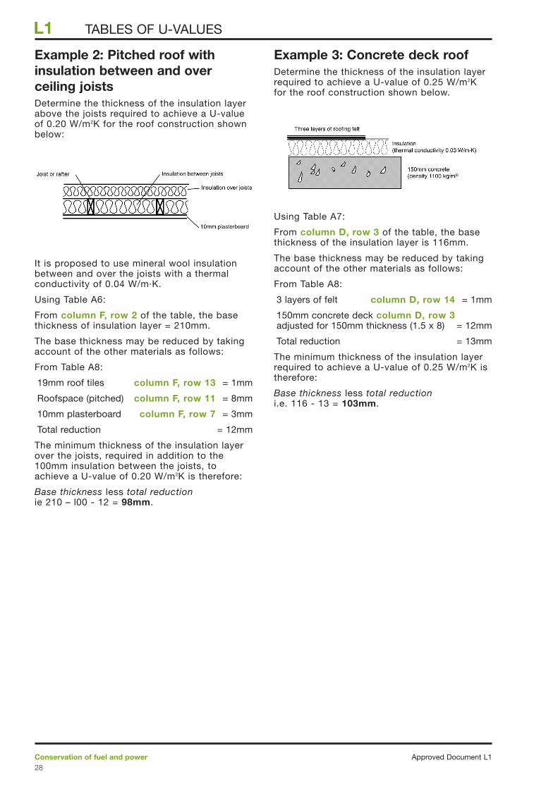
Example 2: Pitched roof withinsulation between and overceiling joistsDetermine the thickness of the insulation layerabove the joists required to achieve a U-valueof 0.20 W/m2K for the roof construction shownbelow:
It is proposed to use mineral wool insulationbetween and over the joists with a thermalconductivity of 0.04 W/m·K.
Using Table A6:
From column F, row 2 of the table, the basethickness of insulation layer = 210mm.
The base thickness may be reduced by takingaccount of the other materials as follows:
From Table A8:
19mm roof tiles column F, row 13 = 1mm
Roofspace (pitched) column F, row 11 = 8mm
10mm plasterboard column F, row 7 = 3mm
Total reduction = 12mm
The minimum thickness of the insulation layerover the joists, required in addition to the100mm insulation between the joists, toachieve a U-value of 0.20 W/m2K is therefore:
Base thickness less total reductionie 210 – l00 - 12 = 98mm.
Example 3: Concrete deck roofDetermine the thickness of the insulation layerrequired to achieve a U-value of 0.25 W/m2Kfor the roof construction shown below.
Using Table A7:
From column D, row 3 of the table, the basethickness of the insulation layer is 116mm.
The base thickness may be reduced by takingaccount of the other materials as follows:
From Table A8:
3 layers of felt column D, row 14 = 1mm
150mm concrete deck column D, row 3adjusted for 150mm thickness (1.5 x 8) = 12mm
Total reduction = 13mm
The minimum thickness of the insulation layerrequired to achieve a U-value of 0.25 W/m2K istherefore:
Base thickness less total reduction i.e. 116 - 13 = 103mm.
Approved Document L1Conservation of fuel and power28
L1 TABLES OF U-VALUES

Walls
Conservation of fuel and powerApproved Document L129
L1TABLES OF U-VALUES
Table A10 Allowable reductions in basethickness for commoncomponentsThermal conductivity of insulant (W/m·K) 0.020 0.025 0.030 0.035 0.040 0.045 0.050
Reduction in base thickness of Component insulating material (mm)
A B C D E F G H
1 Cavity (25mm 4 5 5 6 7 8 9 or more)
2 Outer leaf 3 3 4 5 5 6 6 brickwork
3 13mm 1 1 1 1 1 1 1 plaster
4 13mm 2 2 2 3 3 4 4 lightweight plaster
5 9.5mm 1 2 2 2 3 3 3 plasterboard
6 12.5mm 2 2 2 3 3 4 4 plasterboard
7 Airspace 2 3 4 4 5 5 6 behind plasterboard drylining
8 9mm 1 2 2 2 3 3 3 sheathing ply
9 20mm 1 1 1 1 2 2 2 cement render
10 13mm 0 0 0 1 1 1 1 tile hanging
Table A9 Base thickness of insulationlayer
Thermal conductivity of insulant (W/m·K) 0.020 0.025 0.030 0.035 0.040 0.045 0.050
DesignU-value(W/m2K) Base thickness of insulating material (mm)
A B C D E F G H
1 0.20 97 121 145 169 193 217 242
2 0.25 77 96 115 134 153 172 192
3 0.30 63 79 95 111 127 142 158
4 0.35 54 67 81 94 107 121 134
5 0.40 47 58 70 82 93 105 117
6 0.45 41 51 62 72 82 92 103
Table A11 Allowable reductions in basethickness for concretecomponentsThermal conductivity of insulant (W/m·K) 0.020 0.025 0.030 0.035 0.040 0.045 0.050
Reduction in base thicknessDensity of insulation (mm)(kg/m3) for each 100mm of concrete
A B C D E F G H
Concrete blockwork inner leaf
1 600 9 11 13 15 17 20 22
2 800 7 9 10 12 14 16 17
3 1000 5 6 8 9 10 11 13
4 1200 4 5 6 7 8 9 10
5 1400 3 4 5 6 7 8 8
6 1600 3 3 4 5 6 6 7
7 1800 2 2 3 3 4 4 4
8 2000 2 2 2 3 3 3 4
9 2400 1 1 2 2 2 2 3
Concrete blockwork outer leaf or single leaf wall
10 600 8 11 13 15 17 19 21
11 800 7 9 10 12 14 15 17
12 1000 5 6 7 8 10 11 12
13 1200 4 5 6 7 8 9 10
14 1400 3 4 5 6 6 7 8
15 1600 3 3 4 5 5 6 7
16 1800 2 2 3 3 3 4 4
17 2000 1 2 2 3 3 3 4
18 2400 1 1 2 2 2 2 3
Table A12 Allowable reductions in basethickness for insulatedtimber framed walls
Thermal conductivity of insulant (W/m·K) 0.020 0.025 0.030 0.035 0.040 0.045 0.050
Thermal Reduction in base thicknessconductivity of of insulation material (mm)insulation within for each 100mm of frame (mm)frame (W/m·K)
A B C D E F G H
1 0.035 39 49 59 69 79 89 99
2 0.040 36 45 55 64 73 82 91
NoteThe table is derived for walls for which the proportion of timber is15%, which corresponds to 38mm wide studs at 600mm centres andincludes horizontal noggings etc. and the effects of additionaltimbers at junctions and around openings. For other proportions oftimber the U-value can be calculated using the procedure inAppendix B.

Example 4: Masonry cavity wallwith internal insulationDetermine the thickness of the insulation layerrequired to achieve a U-value of 0.35 W/m2Kfor the wall construction shown below.
Using Table A9:
From column F, row 4 of the table, the basethickness of the insulation layer is 107mm.
The base thickness may be reduced by takingaccount of the other materials as follows:
From Table A10:
Brickwork outer leaf column F, row 2 = 5mm
Cavity column F, row 1 = 7mm
Plasterboard column F, row 6 = 3mm
And from table A11
Concrete blockwork column F, row 1adjusted for 150mm block
thickness (1.5 x 17) = 26mm
Total reduction = 41mm
The minimum thickness of the insulation layerrequired to achieve a U-value of 0.35 W/m2K istherefore:
Base thickness less total reduction i.e. 107 – 41 = 66mm.
Example 5: Masonry cavity wall(tied with vertical-twist stainless-steel ties) filled with insulationwith plasterboard on dabsDetermine the thickness of the insulation layerrequired to achieve a U-value of 0.37 W/m2Kfor the wall construction shown below. FromTable A4 there is a ∆U correction for the wallties of 0.02 W/m2K which applies. To allowfor this, the ‘look-up’ U-value is reducedby 0.02 W/m2K to 0.35 W/m2K.
Using Table A9:
From column F, row 4 of the table, the basethickness of the insulation layer is 107mm.
The base thickness may be reduced by takingaccount of the other materials as follows:
From Table A10:
Brickwork outer leaf column F, row 2 = 5mm
Plasterboard column F, row 6 = 3mm
Airspace behind plasterboard column F, row 7 = 5mm
And from Table A11:
Concrete blockwork column F, row 1 = 3mm
Total reduction = 16mm
The minimum thickness of the insulation layerrequired to achieve a U-value of 0.37 W/m2K(including ∆U for the wall ties) is therefore:
Base thickness less total reduction i.e. 107 – 16 = 91mm.
102 mm brickwork outer leaf
Cavity filled with insulation(thermal conductivity 0.040 W/m·K)
100 mm dense aggregate blockwork (density 2000 kg/m3)
12.5 mm plasterboard on dabs
heat flow
airspace between dabs
102 mm brickwork outer leaf
50 mm cavity
150 mm AAC blockwork (density 600 kg/m3 )
thermal insulation
(thermal conductivity 0.040 W/m·K)
12.5 mm plasterboard
heat flow
Approved Document L1Conservation of fuel and power30
L1 TABLES OF U-VALUES

Example 6: Masonry wall (tiedwith vertical-twist stainless-steelties) with partial cavity-fillDetermine the thickness of the insulation layerrequired to achieve a U-value of 0.32 W/m2Kfor the wall construction shown below. FromTable A4 there is a ∆U correction for the wallties of 0.02 W/m2K which applies. To allowfor this, the ‘look-up’ U-value is reducedby 0.02 W/m2K to 0.30 W/m2K.
Using Table A9:
From column C, row 3 of the table, the basethickness of the insulation layer is 79mm.
The base thickness may be reduced by takingaccount of the other materials as follows:
From Table A10:
Brickwork outer leaf column C, row 2 = 3mm
Cavity column C, row 1 = 5mm
Lightweight plaster column C, row 4 = 2mm
And from Table A11:
Concrete blockwork column C, row 5 = 4mm
Total reduction = 14mm
The minimum thickness of the insulation layerrequired to achieve a U-value of 0.3 W/m2K(including ∆U for the wall ties) is therefore:
Base thickness less total reduction i.e. 79 – 14 = 65mm.
Example 7: Timber-framed wallDetermine the thickness of the insulation layerrequired to achieve a U-value of 0.35 W/m2Kfor the wall construction shown below.
Using Table A9:
From column F, row 4 of the table, the basethickness of the insulation layer is 107mm.
The base thickness may be reduced by takingaccount of the other materials as follows:
From Table A10:
Brickwork outer leaf column F, row 2 = 5mm
Cavity column F, row 1 = 7mm
Sheathing ply column F, row 8 = 3mm
Plasterboard column F, row 6 = 3mm
Plasterboard column F, row 6 = 3mm
And from Table A12:
Timber frame column F, row 2adjusted for
stud thickness (73mm x 90/100) = 66mm
Total reduction = 87mm
The minimum thickness of the insulation layerrequired to achieve a U-value of 0.35 W/m2K istherefore:
Base thickness less total reductioni.e. 107 - 87 = 20mm.
102 mm brickwork outer leaf
Insulation (thermal conductivity 0.04 W/m·K)
90 mm timber frame filled with insulation(thermal conductivity 0.04 W/m·K)
two sheets of 12.5 mm plasterboard
heat flow
50 mm cavity
9 mm plywood
102 mm brickwork outer leaf
Partial fill cavity insulation(thermal conductivity 0.025 W/m·K)
100 mm lightweight aggregate blockwork
(density 1400 kg/m 3 )
13 mm lightweight plaster
heat flow
50 mm residual cavity
Conservation of fuel and powerApproved Document L131
L1TABLES OF U-VALUES

Ground floorsNote: in using the tables for floors it is firstnecessary to calculate the ratio P/A, where P isthe floor perimeter length in metres and A isthe floor area in square metres.
Approved Document L1Conservation of fuel and power32
L1
Table A14 Insulation thickness forsuspended timber groundfloors
Insulation thickness (mm) forU-value of 0.20 W/m2K
Thermal conductivity of insulant (W/m.K)
P/A 0.020 0.025 0.030 0.035 0.040 0.045 0.050
A B C D E F G H
1 1.00 127 145 164 182 200 218 236
2 0.90 125 144 162 180 198 216 234
3 0.80 123 142 160 178 195 213 230
4 0.70 121 139 157 175 192 209 226
5 0.60 118 136 153 171 188 204 221
6 0.50 114 131 148 165 181 198 214
7 0.40 109 125 141 157 173 188 204
8 0.30 99 115 129 144 159 173 187
9 0.20 82 95 107 120 132 144 156
U-value of 0.25 W/m2K
10 1.00 93 107 121 135 149 162 176
11 0.90 92 106 119 133 146 160 173
12 0.80 90 104 117 131 144 157 170
13 0.70 88 101 114 127 140 153 166
14 0.60 85 98 111 123 136 148 161
15 0.50 81 93 106 118 130 142 154
16 0.40 75 87 99 110 121 132 143
17 0.30 66 77 87 97 107 117 127
18 0.20 49 57 65 73 81 88 96
U-value of 0.30 W/m2K
19 1.00 71 82 93 104 114 125 135
20 0.90 70 80 91 102 112 122 133
21 0.80 68 78 89 99 109 119 129
22 0.70 66 76 86 96 106 116 126
23 0.60 63 73 82 92 102 111 120
24 0.50 59 68 78 87 96 104 113
25 0.40 53 62 70 79 87 95 103
26 0.30 45 52 59 66 73 80 87
27 0.20 28 33 38 42 47 51 56
NotesP/A is the ratio of floor perimeter (m) to floor area (m2). The table isderived for suspended timber floors for which the proportion oftimber is 12%, which corresponds to 48mm wide timbers at 400mmcentres.
TABLES OF U-VALUES
Table A13 Insulation thickness for solid floors in contact withthe ground
Insulation thickness (mm) forU-value of 0.20 W/m2K
Thermal conductivity of insulant (W/m.K)
P/A 0.020 0.025 0.030 0.035 0.040 0.045 0.050
A B C D E F G H
1 1.00 81 101 121 142 162 182 202
2 0.90 80 100 120 140 160 180 200
3 0.80 78 98 118 137 157 177 196
4 0.70 77 96 115 134 153 173 192
5 0.60 74 93 112 130 149 167 186
6 0.50 71 89 107 125 143 160 178
7 0.40 67 84 100 117 134 150 167
8 0.30 60 74 89 104 119 134 149
9 0.20 46 57 69 80 92 103 115
U-value of 0.25 W/m2K
10 1.00 61 76 91 107 122 137 152
11 0.90 60 75 90 105 120 135 150
12 0.80 58 73 88 102 117 132 146
13 0.70 57 71 85 99 113 128 142
14 0.60 54 68 82 95 109 122 136
15 0.50 51 64 77 90 103 115 128
16 0.40 47 59 70 82 94 105 117
17 0.30 40 49 59 69 79 89 99
18 0.20 26 32 39 45 52 58 65
U-value of 0.30 W/m2K
19 1.00 48 60 71 83 95 107 119
20 0.90 47 58 70 81 93 105 116
21 0.80 45 56 68 79 90 102 113
22 0.70 43 54 65 76 87 98 108
23 0.60 41 51 62 72 82 92 103
24 0.50 38 47 57 66 76 85 95
25 0.40 33 42 50 59 67 75 84
26 0.30 26 33 39 46 53 59 66
27 0.20 13 16 19 22 25 28 32
NoteP/A is the ratio of floor perimeter (m) to floor area (m2).

Example 8: Solid floor in contactwith the groundDetermine the thickness of the insulation layerrequired to achieve a U-value of 0.3 W/m2K forthe ground floor slab shown below.
It is proposed to use insulation with a thermalconductivity of 0.025 W/m·K.
The overall perimeter length of the slab is (10 + 4 + 4 + 2 + 6 + 6) = 32m.
The floor area of the slab is (6 x 6) + (4 x 4) = 52 m2.
The ratio:
Using Table A13, column C, row 23 indicatesthat 51mm of insulation is required.
Example 9: Suspended timberfloorIf the floor shown above was of suspendedtimber construction, the perimeter length andfloor area would be the same, yielding thesame ratio of:
To achieve a U-value of 0.30 W/m2·K, usinginsulation with a thermal conductivityof 0.04 W/mK, Table A14 column F, row 23indicates that the insulation thickness betweenthe joists should be not less than 102mm.
perimeter lengthfloor area
3252
= = 0.6
perimeter lengthfloor area
3252
= = 0.6
10m
6m 4m
2m
4m6m
Conservation of fuel and powerApproved Document L133
L1TABLES OF U-VALUES
Table A15 Insulation thickness forsuspended concrete beamand block ground floors
Insulation thickness (mm) forU-value of 0.20 W/m2K
Thermal conductivity of insulant (W/m.K)
P/A 0.020 0.025 0.030 0.035 0.040 0.045 0.050
A B C D E F G H
1 1.00 82 103 123 144 164 185 205
2 0.90 81 101 122 142 162 183 203
3 0.80 80 100 120 140 160 180 200
4 0.70 79 99 118 138 158 177 197
5 0.60 77 96 116 135 154 173 193
6 0.50 75 93 112 131 150 168 187
7 0.40 71 89 107 125 143 161 178
8 0.30 66 82 99 115 132 148 165
9 0.20 56 69 83 97 111 125 139
U-value of 0.25 W/m2K
10 1.00 62 78 93 109 124 140 155
11 0.90 61 76 92 107 122 138 153
12 0.80 60 75 90 105 120 135 150
13 0.70 59 74 88 103 118 132 147
14 0.60 57 71 86 100 114 128 143
15 0.50 55 68 82 96 110 123 137
16 0.40 51 64 77 90 103 116 128
17 0.30 46 57 69 80 92 103 115
18 0.20 36 45 54 62 71 80 89
U-value of 0.30 W/m2K
19 1.00 49 61 73 85 97 110 122
20 0.90 48 60 72 84 96 108 120
21 0.80 47 59 70 82 94 105 117
22 0.70 45 57 68 80 91 102 114
23 0.60 44 55 66 77 88 98 109
24 0.50 41 52 62 72 83 93 104
25 0.40 38 48 57 67 76 86 95
26 0.30 33 41 49 57 65 73 81
27 0.20 22 28 33 39 44 50 56
NoteP/A is the ratio of floor perimeter (m) to floor area (m2).

Approved Document L1Conservation of fuel and power34
L1
Table A19 Thermal conductivity ofsome common buildingmaterials
Density Conductivity (kg/m2) (W/m·K)
Walls
Brickwork (outer leaf) 1700 0.77Brickwork (inner leaf) 1700 0.56Lightweight aggregate concrete block 1400 0.57Autoclaved aerated concrete block 600 0.18Concrete (medium density) (inner leaf) 1800 1.13
2000 1.332200 1.59
Concrete (high density) 2400 1.93Reinforced concrete (1% steel) 2300 2.3Reinforced concrete (2% steel) 2400 2.5Mortar (protected) 1750 0.88Mortar (exposed) 1750 0.94Gypsum 600 0.18
900 0.31200 0.43
Gypsum plasterboard 900 0.25Sandstone 2600 2.3Limestone (soft) 1800 1.1Limestone (hard) 2200 1.7Fibreboard 400 0.1Plasterboard 900 0.25Tiles (ceramic) 2300 1.3Timber (softwood, plywood, chipboard) 500 0.13Timber (hardwood) 700 0.18
Wall ties (stainless steel) 7900 17.0
Surface finishes
External rendering 1300 0.57 Plaster (dense) 1300 0.57
Plaster (lightweight) 600 0.18
Roofs
Aerated concrete slab 500 0.16Asphalt 2100 0.7Felt/bitumen layers 1100 0.23Screed 1200 0.41Stone chippings 2000 2.0Tiles (clay) 2000 1.0Tiles (concrete) 2100 1.5
Wood wool slab 500 0.1
Floors
Cast concrete 2000 1.35Metal tray (steel) 7800 50.0Screed 1200 0.41Timber (softwood), plywood, chipboard 500 0.13
Timber (hardwood) 700 0.18
Insulation
Expanded polystyrene (EPS) board 15 0.04Mineral wool quilt 12 0.042Mineral wool batt 25 0.038Phenolic foam board 30 0.025
Polyurethane board 30 0.025
NoteIf available, certified test values should be used in preference tothose in the table.
TABLES OF U-VALUES
Table A16 Upper floors of timberconstruction
Thermal conductivity of insulant (W/m·K) 0.020 0.025 0.030 0.035 0.040 0.045 0.050
DesignU-value(W/m2K) Base thickness of insulation between
joints to achieve design U-values
A B C D E F G H
1 0.20 167 211 256 298 341 383 426
2 0.25 109 136 163 193 225 253 281
3 0.30 80 100 120 140 160 184 208
NoteTable A16 is derived for floors with the proportion of timber at 12%which corresponds to 48mm wide timbers at 400mm centres. Forother proportions of timber the U-value can be calculated using theprocedure in Appendix B.
Table A17 Upper floors of concreteconstruction
Thermal conductivity of insulant (W/m·K) 0.020 0.025 0.030 0.035 0.040 0.045 0.050
DesignU-value(W/m2K) Base thickness of insulation
to achieve design U-values
A B C D E F G H
1 0.20 95 119 142 166 190 214 237
2 0.25 75 94 112 131 150 169 187
3 0.30 62 77 92 108 123 139 154
Table A18 Upper floors: allowablereductions in base thicknessfor common componentsThermal conductivity of insulant (W/m·K) 0.020 0.025 0.030 0.035 0.040 0.045 0.050
Component Reduction in base thickness of insulating material (mm)
A B C D E F G H
1 10mm 1 2 2 2 3 3 3 plasterboard
2 19mm 3 3 4 5 5 6 7 timber flooring
3 50mm 2 3 4 4 5 5 6 screed
Building materialsUpper floors

IntroductionB1 For building elements which containrepeating thermal bridges, such as timber joistsbetween insulation in a roof or mortar jointsaround lightweight blockwork in a wall, theeffect of thermal bridges should be taken intoaccount when calculating the U-value. Otherfactors, such as metal wall ties and air gapsaround insulation should also be included. Thecalculation method, known as the CombinedMethod, is set out in BS EN ISO 6946 and thefollowing examples illustrate the use of themethod for typical wall, roof and floor designs.
B2 In cases where the joists in roof, wall orfloor constructions project beyond the surfaceof the insulation, the depths of the joists shouldbe taken to be the same as the thickness ofinsulation for the purposes of the U-valuecalculation (as specified in BS EN ISO 6946).
B3 Thermal conductivity values for commonbuilding materials can be obtained from theCIBSE Guide Section A3 or fromEN ISO 12524. For specific insulationproducts, however, data should be obtainedfrom manufacturers.
B4 The procedure in this Appendix does notapply to elements containing metal connectingpaths, for which the reader is directed toBRE IP 5/98 for metal cladding and toBS EN ISO 10211-1 and -2 for other cases, andit does not deal with ground floors andbasements (which are dealt with in Appendix C).
B5 The examples are offered as indicatingways of meeting the requirements of Part L butdesigners also have to ensure that theirdesigns comply with all the other parts ofSchedule 1 to the Building Regulations.
The procedureB6 The U-value is calculated by applying thefollowing steps:
a) Calculate the upper resistance limit (Rupper)by combining in parallel the total resistances ofall possible heat-flow paths (i.e. sections)through the plane building element.
b) Calculate the lower resistance limit (Rlower)by combining in parallel the resistances of theheat flow paths of each layer separately andthen summing the resistances of all layers ofthe plane building element.
c) Calculate the U-value of the element from U = 1/RT,
d) Adjust the U-value as appropriate to takeaccount of metal fasteners and air gaps.
Example 1: Cavity wallwith lightweight masonryleaf and insulated dry-liningIn this example there are two bridged layers -insulation bridged by timber and lightweightblockwork bridged by mortar (for a singlebridged layer see the next example).
Diagram B1: Wall construction with twobridged layers
(Total thickness 353.5mm, U = 0.32 W/m2K)
Layer Material Thickness Thermal Thermal (mm) conductivity resistance
(W/m·K) (m2K/W)
external surface - - 0.040
1 outer leaf 102 0.77 0.132brickwork
2 air cavity 50 - 0.180(unvented)
3(a) AAC blocks 100 0.11 0.909(93%)
3(b) mortar (7%) (100) 0.88 0.114
4(a) mineral wool 89 0.038 2.342(88%)
4(b) timber battens (89) 0.13 0.685(12%)
5 plasterboard 12.5 0.25 0.050
internal surface - - 0.130
102 mm brickwork, thermal conductivity 0.77 W/m·K
50 mm air cavity, thermal resistance 0.18 m2K/W
100 mm AAC blocks, thermal conductivity 0.11 W/m·K,bridged by mortar, thermal conductivity 0.88 W/m·K
mineral wool (conductivity 0.038 W/m·K)between 48 x 89 mm timber studs(conductivity 0.13 W/m·K) at 400 mm centres
12.5 mm plasterboard,(conductivity 0.25 W/m·K)
R upper + R lower
2where R1 =
Conservation of fuel and powerApproved Document L135
L1
Appendix B: Calculating U-valuesCALCULATING U-VALUES

Upper resistance limitThere are four possible sections (or paths)through which heat can pass. The upper limitof resistance is therefore given by Rupper = 1/(F1/R1 + ... + F4/R4) where Fm is thefractional area of section m and Rm is the totalthermal resistance of section m. A conceptualillustration of the upper limit of resistance isshown in Diagram B2.
Diagram B2: Conceptual illustration of theupper limit of resistance
Resistance through section containing AACblocks and mineral wool
External surface resistance = 0.040
Resistance of brickwork = 0.132
Resistance of air cavity = 0.180
Resistance of AAC blocks = 0.909
Resistance of mineral wool = 2.342
Resistance of plasterboard = 0.050
Internal surface resistance = 0.130
Total thermal resistance R1 = 3.783 m2K/W
Fractional area F1= 93% x 88% = 0.818
Resistance through section containingmortar and mineral wool
External surface resistance = 0.040
Resistance of brickwork = 0.132
Resistance of air cavity = 0.180
Resistance of mortar = 0.114
Resistance of mineral wool = 2.342
Resistance of plasterboard = 0.050
Internal surface resistance = 0.130
Total thermal resistance R2 = 2.988 m2K/W
Fractional area F2= 7% x 88% = 0.062
Resistance through section containing AACblocks and timber
External surface resistance = 0.040
Resistance of brickwork = 0.132
Resistance of air cavity = 0.180
Resistance of AAC blocks = 0.909
Resistance of timber = 0.685
Resistance of plasterboard = 0.050
Internal surface resistance = 0.130
Total thermal resistance R3 = 2.126 m2K/W
Fractional area F3= 93% x 12% = 0.112
Resistance through section containingmortar and timber
External surface resistance = 0.040
Resistance of brickwork = 0.132
Resistance of air cavity = 0.180
Resistance of mortar = 0.114
Resistance of timber = 0.685
Resistance of plasterboard = 0.050
Internal surface resistance = 0.130
Total thermal resistance R4 = 1.331 m2K/W
Fractional area F4= 7% x 12% = 0.008
Combining these resistances we obtain:
= 3.382 m2K/W.
Lower resistance limitA conceptual illustration of the lower limit ofresistance is shown in the Diagram B3.
Diagram B3: Conceptual illustration of thelower limit of resistance
4(a)
21 5 internalsurface
3(a)
externalsurface
4(b)3(b)
R upper = F1
R1+
F2
R2+
F3
R3+
F4
R4
10.8183.783
+0.0622.988
+0.1122.126
+0.0081.331
1=
externalsurface
internalsurface
1 4(a)2
2
2
2
1
53(b)
F1
F2
3(a) 4(b) 5F3
F4
3(b)
3(a) 4(a)
4(b) 5
5
1
1
Approved Document L1Conservation of fuel and power36
L1 CALCULATING U-VALUES

The resistances of the layers are addedtogether to give the lower limit of resistance.The resistance of the bridged layer consistingof AAC blocks and mortar is calculated using:
and the resistance of the bridged layerconsisting of insulation and timber is calculatedusing:
The lower limit of resistance is then obtainedby adding together the resistances of thelayers:
External surface resistance = 0.040
Resistance of brickwork = 0.132
Resistance of air cavity = 0.180
Resistance of first bridged layer (blocks andmortar)
= 0.611
Resistance of second bridged layer (insulationand timber)
= 1.815
Resistance of plasterboard = 0.050
Internal surface resistance = 0.130
Total (Rlower) = 2.958 m2K/W
Total resistance of wall
The total resistance of the wall is the averageof the upper and lower limits of resistance:
= 3.170 m2K/W.
Correction for air gapsIf there are small air gaps penetrating theinsulating layer a correction should be appliedto the U-value. The correction for air gaps is∆Ug, where
∆Ug = ∆U'' x (RI / RT) 2
and where RI is the thermal resistance of thelayer containing gaps, RT is the total resistance
of the element and ∆U'' is a factor whichdepends upon the way in which the insulationis fitted. In this example R I is 1.815 m2K/W,RT is 3.170 m2K/W and ∆U'' is 0.01 (iecorrection level 11). The value of ∆Ug is then
∆Ug = 0.01 x (1.815/3.170) 2 = 0.003 W/m2K.
U-value of the wallThe effect of air gaps or mechanical fixings 2
should be included in the U-value unless theylead to an adjustment in the U-value of lessthan 3%.
U = 1/RT + ∆Ug (if ∆Ug is not less than3% of 1/RT)
U = 1/RT (if ∆Ug is less than 3% of 1/RT)
In this case ∆Ug = 0.003 W/m2K and1/RT = 0.315 W/m2K, i.e. ∆Ug is less than3% of (1/RT).
Therefore U = 1/RT = 1/3.170 = 0.32 W/m2K(expressed to two decimal places).
R T =2
R upper + R lower
23.382 + 2.958
=
0.882.342
0.120.685
+
1=
0.930.909
0.070.114
+
1=
R =F insul
R insul
F timber
R timber+
1
R =F blocks
R blocks
F mortar
R mortar+
1
Conservation of fuel and powerApproved Document L137
L1CALCULATING U-VALUES
1 Applies for “Insulation installed in such a way that noair circulation is possible on the warm side of theinsulation; air gaps may penetrate the insulation layer”
2 In this case the wall ties within the cavity do notpenetrate any insulating layer and their effects need notbe taken into account

Example 2: Timber framedwallIn this example there is a single bridged layerin the wall, involving insulation bridged bytimber studs. The construction consists ofouter leaf brickwork, a clear ventilated cavity,10mm plywood, 38 x 140mm timber framingwith 140mm of mineral wool quilt insulationbetween the timber studs and 2 sheets ofplasterboard, each 12.5mm thick, incorporatinga vapour check.
The timber fraction in this particular example is15%. This corresponds to 38mm wide studs at600mm centres and includes horizontalnoggings etc. and the effects of additionaltimbers at junctions and around openings.
Diagram B4: Timber framed wallconstruction
(Total thickness 327mm, U = 0.30 W/m2K)
The thicknesses of each layer, together withthe thermal conductivities of the materials ineach layer, are shown below. The internal andexternal surface resistances are thoseappropriate for wall constructions. Layer 4 isthermally bridged and two thermalconductivities are given for this layer, one forthe main part and one for the bridging part ofthe layer. For each homogeneous layer and foreach section through a bridged layer, thethermal resistance is calculated by dividing thethickness (in metres) by the thermalconductivity.
Layer Material Thickness Thermal Thermal (mm) conductivity resistance
(W/m·K) (m2K/W)
external surface - - 0.040
1 outer leaf brick 102 0.77 0.132
2 ventilated 50 - 0.090air cavity
3 plywood 10 0.13 0.077
4(a) mineral wool 140 0.038 3.684quilt between timber framing (85%)
4(b) timber framing (140) 0.13 1.077(15%)
5 plasterboard 25 0.25 0.100
internal surface - - 0.130
Both the upper and the lower limits of thermalresistance are calculated by combining thealternative resistances of the bridged layer inproportion to their respective areas, asillustrated below. The method of combiningdiffers in the two cases.
Upper resistance limitWhen calculating the upper limit of thermalresistance, the building element is consideredto consist of two thermal paths (or sections).The upper limit of resistance is calculated from:
where F1 and F2 are the fractional areas of thetwo sections (paths) and R1 and R2 are the totalresistances of the two sections. The method ofcalculating the upper resistance limit isillustrated conceptually in Diagram B5.
Diagram B5: Conceptual illustration of howto calculate the upper limit of thermalresistance
external
surface
internal
surface
1 4(a)2
21
3
F1
F2
3 4(b)
5
5
R upper = F1
R1+
F2
R2
1
102 mm brickwork outer leaf (conductivity 0.77 W/mK)
25 mm plasterboard (conductivity 0.25 W/mK)
heat flow
50 mm ventilated cavity (resistance 0.09 mK/W)
10 mm plywood (conductivity 0.13 W/mK)
140 mm mineral wool batts (conductivity 0.038 W/mK)between timber framing (conductivity 0.13 W/mK)
2
Approved Document L1Conservation of fuel and power38
L1 CALCULATING U-VALUES

Resistance through the section containinginsulation
External surface resistance = 0.040
Resistance of bricks = 0.132
Resistance of air cavity = 0.090
Resistance of plywood = 0.077
Resistance of mineral = 3.684wool (85%)
Resistance of plasterboard = 0.100
Internal surface resistance = 0.130
Total (R1) = 4.253
Fractional area F1 = 0.85 (85%)
The resistance through this section is therefore4.253 m2K/W.
Resistance through section containingtimber stud
External surface resistance = 0.040
Resistance of bricks = 0.132
Resistance of air cavity = 0.090
Resistance of plywood = 0.077
Resistance of timber = 1.077studs (15%)
Resistance of plasterboard = 0.100
Internal surface resistance = 0.130
Total (R2) = 1.646
Fractional area F2 = 0.15 (15%)
The resistance through this section is therefore1.646 m2K/W.
The upper limit of resistance is then:
= 3.437 m2K/W.
Lower resistance limitWhen calculating the lower limit of thermalresistance, the resistance of a bridged layer isdetermined by combining in parallel theresistances of the unbridged part and thebridged part of the layer. The resistances of allthe layers in the element are then addedtogether to give the lower limit of resistance.
The resistance of the bridged layer iscalculated using:
The method of calculating the lower limit ofresistance is illustrated conceptually inDiagram B6.
Diagram B6: Conceptual illustration of howto calculate the lower limit of thermalresistance
The lower limit of resistance is then obtainedby adding up the resistances of all the layers:
External surface resistance = 0.040
Resistance of bricks = 0.132
Resistance of air cavity = 0.090
Resistance of plywood = 0.077
Resistance of bridged layer = = 2.703
Resistance of plasterboard = 0.100
Internal surface resistance = 0.130
Total (Rlower) = 3.272
The lower limit of resistance is then 3.272 m2K/W.
Total resistance of wall (notallowing for air gaps around theinsulation)The total resistance of the wall is the averageof the upper and lower resistance limits:
= 3.354 m2K/W.
Correction for air gaps If there are small air gaps penetrating theinsulating layer a correction should be appliedto the U-value to account for this. Thecorrection for air gaps is ∆Ug, where
∆Ug = ∆U'' x (RI/RT) 2
and where RI is the thermal resistance of thelayer containing gaps, RT is the total resistance
R T =2
R upper + R lower
23.437 + 3.272
=
0.853.684
+0.151.077
1
4(a)
21 5
F1
F2
internal
surface
3
4(b)
external
surface
R =F insul
R insul
F timber
R timber+
1
R upper = F1
R1+
F2
R2
10.854.253
+0.151.646
1=
Conservation of fuel and powerApproved Document L139
L1CALCULATING U-VALUES

of the element and ∆U'' is a factor whichdepends upon the way in which the insulationis fitted. In this example RI is 2.703 m2K/W,RT is 3.354 m2K/W and ∆U'' is 0.01(ie correction level 1). The value of ∆Ug is then
∆Ug = 0.01 x (2.703/3.354) 2 = 0.006 W/m2K.
U-value of the wallThe effect of air gaps or mechanical fixingsshould be included in the U-value unless theylead to an adjustment in the U-value of lessthan 3%.
U = 1/RT + ∆Ug (if ∆Ug is not less than3% of 1/RT)
U = 1/RT (if ∆Ug is less than 3% of 1/RT)
In this case ∆Ug = 0.006 W/m2K and 1/RT = 0.298 W/m2K. Since ∆Ug is less than3% of (1/RT),
U = 1/RT = 1 / 3.354 = 0.30 W/m2K.
Approved Document L1Conservation of fuel and power40
L1 CALCULATING U-VALUES

C1 The guidance in this Approved Documentstates that a ground floor should not have a U-value exceeding 0.25 W/m2K if the ElementalMethod of compliance is to be used. This cannormally be achieved without the need forinsulation if the perimeter to area ratio is lessthan 0.12 m/m2 for solid ground floors or lessthan 0.09 m/m2 for suspended floors. For mostbuildings, however, some ground floorinsulation will be necessary to achieve this U-value or better performance. For exposedfloors and for floors over unheated spaces thereader is referred to BS EN ISO 6946 or theCIBSE Guide Section A3.
C2 This Appendix provides a simple methodfor determining U-values which will suffice formost common constructions and groundconditions in the UK. More rigorous proceduresare given in BS EN ISO 13370 and in CIBSEGuide Section A3 (1999 edition).
C3 For ground floors the U-value dependsupon the type of soil beneath the building.Where the soil type is unknown, clay soilshould be assumed as this is the most typicalsoil type in the UK. The tables which followare based on this soil type. Where the soil isnot clay or silt, the U-value should becalculated using the procedure inBS EN ISO 13370.
C4 Floor dimensions should be measuredbetween finished internal faces of the externalelements of the building including anyprojecting bays. In the case of semi-detachedor terraced premises, blocks of flats andsimilar, the floor dimensions can either betaken as those of the premises themselves, orof the whole building. When consideringextensions to existing buildings the floordimensions may be taken as those of thecomplete building including the extension.
C5 Floor designs should prevent excessivethermal bridging at the floor edge so that therisk of condensation and mould are reasonablycontrolled. See BRE Report BR 262 Thermalinsulation: avoiding risks.
C6 Unheated spaces outside the insulatedfabric, such as attached garages or porches,should be excluded when determining theperimeter and area but the length of the wallbetween the heated building and the unheatedspace should be included when determiningthe perimeter.
C7 Data on U-values and insulationthicknesses for basements are given in theBCA/NHBC Approved Document “Basementsfor dwellings”, ISBN 0-7210-1508-5.
Example of how to obtainU-values from the tablesThe following example illustrates the use of thetables by interpolating between appropriaterows or columns.
A proposed building has a perimeter of 38.4 mand a ground floor area of 74.25m2. The floorconstruction consists of a 150mm concreteslab, 95mm of rigid insulation (thermalconductivity 0.04 W/m·K) and a 65mm screed.Only the insulation layer is included in thecalculation of the thermal resistance.
Diagram C1
The perimeter to area ratio is equal to (38.4 ⁄ 74.25 = 0.517) m/m2. Table C1 providesvalues for perimeter/area ratios of 0.50 and0.55 but not for any values between 0.50 and0.55. In this case, the U-value correspondingto a perimeter to area ratio of 0.50 should beused since 0.517 is closer to 0.50 than to 0.55.
The thermal resistance of the insulation isobtained by dividing the thickness (in metres)by the conductivity. The resistance is then0.095 ⁄ 0.04 = 2.375 m2K/W.
The relevant part of table C1 is shown below:
Thermal resistance of all-over insulation (m2K/W)
perimeter/area 2.0 2.5
0.50 0.28 0.24
Conservation of fuel and powerApproved Document L141
L1
Appendix C: U-values of ground floorsU-VALUES OF GROUND FLOORS
9.0m
6.3m
3.7m
6.5m
10.2m
2.7m

The U-value corresponding to a thermalresistance of 2.375 m2K/W is obtained by linearinterpolation as below:
= 0.28 x 0.25 + 0.24 x 0.75
= 0.25 W/m2K
The U-value of this ground floor is therefore 0.25 W/m2K.
NoteIn the example for Table C1 the appropriaterow was chosen and interpolation was carriedout between the appropriate columns. For allof the other tables, however, the appropriatecolumn in the table should be selected andinterpolation should be carried out between theappropriate rows.
Solid ground floorsListed in Table C1 are U-values for solid groundfloors. U-values are given in the followingtable for various perimeter-to-area ratios for arange of insulation levels. Where the floor isuninsulated the column corresponding to athermal resistance of 0 should be used.
Ground floors with edgeinsulationWhere horizontal or vertical edge insulation isused instead of all-over floor insulation, (P/A) xΨ is added to the U-value to account for theeffects of edge insulation, where P/A is theperimeter (m) to area (m2) ratio and Ψ is theedge insulation factor obtained from one of thefollowing two tables. Since the term (P/A) x Ψis negative it reduces the U-value of the groundfloor. The tables apply only to floors withoutoverall insulation.
For floors with both all-over insulation andedge insulation the calculation method inBS EN ISO 13370 can be used.
U = 0.28 x + 0.24 x2.5 – 2.3752.5 – 2.0
2.375 – 2.02.5 – 2.0
Approved Document L1Conservation of fuel and power42
L1 U-VALUES OF GROUND FLOORS
Table C1 U-values (W/m2K) for solidground floors
Thermal resistance of all-over insulation(m2K/W)
perimeter/ 0 0.5 1 1.5 2 2.5area (m/m2)
0.05 0.13 0.11 0.10 0.09 0.08 0.08
0.10 0.22 0.18 0.16 0.14 0.13 0.12
0.15 0.30 0.24 0.21 0.18 0.17 0.15
0.20 0.37 0.29 0.25 0.22 0.19 0.18
0.25 0.44 0.34 0.28 0.24 0.22 0.19
0.30 0.49 0.38 0.31 0.27 0.23 0.21
0.35 0.55 0.41 0.34 0.29 0.25 0.22
0.40 0.60 0.44 0.36 0.30 0.26 0.23
0.45 0.65 0.47 0.38 0.32 0.27 0.23
0.50 0.70 0.50 0.40 0.33 0.28 0.24
0.55 0.74 0.52 0.41 0.34 0.28 0.25
0.60 0.78 0.55 0.43 0.35 0.29 0.25
0.65 0.82 0.57 0.44 0.35 0.30 0.26
0.70 0.86 0.59 0.45 0.36 0.30 0.26
0.75 0.89 0.61 0.46 0.37 0.31 0.27
0.80 0.93 0.62 0.47 0.37 0.32 0.27
0.85 0.96 0.64 0.47 0.38 0.32 0.28
0.90 0.99 0.65 0.48 0.39 0.32 0.28
0.95 1.02 0.66 0.49 0.39 0.33 0.28
1.00 1.05 0.68 0.50 0.40 0.33 0.28
Table C2 Edge insulation factor ΨΨ(W/m·K) for horizontal edgeinsulation
insulation thermal resistance of insulation width (m2K/W)
(m) 0.5 1.0 1.5 2.0
0.5 -0.13 -0.18 -0.21 -0.22
1.0 -0.20 -0.27 -0.32 -0.34
1.5 -0.23 -0.33 -0.39 -0.42
Table C3 Edge insulation factor ΨΨ(W/m·K) for vertical edgeinsulation
insulation thermal resistance of insulation depth (m2K/W)
(m) 0.5 1.0 1.5 2.0
0.25 -0.13 -0.18 -0.21 -0.22
0.50 -0.20 -0.27 -0.32 -0.34
0.75 -0.23 -0.33 -0.39 -0.42
1.00 -0.26 -0.37 -0.43 -0.48

Uninsulated suspendedground floorsThe following table gives U-values ofuninsulated suspended floors for variousperimeter to area ratios and for two levels ofventilation (expressed in m2/m) below the floordeck. The data apply for the floor deck at aheight not more than 0.5 m above the externalground level where the wall surrounding theunderfloor space is uninsulated.
Insulated suspendedfloorsThe U-value of an insulated suspended floorshould be calculated using
U = 1/[(1/U0) – 0.2 + Rf]
where U0 is the U-value of an uninsulatedsuspended floor obtained using Table C4 oranother approved method. Rf, the thermalresistance of the floor deck, is determined fromUf, the U-value of the floor deck, where
and where Uf takes account of any thermalbridging in the floor deck and is calculated asrecommended in BS EN ISO 6946 or bynumerical modelling. The two values “0.17” arethe two surface resistances.
R f = Uf
1– 0.17 – 0.17
Conservation of fuel and powerApproved Document L143
L1U-VALUES OF GROUND FLOORS
Table C4 U-values (W/m2K) ofuninsulated suspended floors
perimeter to Ventilation opening area area ratio per unit perimeter
(m/m2) of underfloor space
0.0015 m2/m 0.0030 m2/m
0.05 0.15 0.15
0.10 0.25 0.26
0.15 0.33 0.35
0.20 0.40 0.42
0.25 0.46 0.48
0.30 0.51 0.53
0.35 0.55 0.58
0.40 0.59 0.62
0.45 0.63 0.66
0.50 0.66 0.70
0.55 0.69 0.73
0.60 0.72 0.76
0.65 0.75 0.79
0.70 0.77 0.81
0.75 0.80 0.84
0.80 0.82 0.86
0.85 0.84 0.88
0.90 0.86 0.90
0.95 0.88 0.92
1.00 0.89 0.93

D1 Within the Elemental Method ofcompliance it is permissible to have windows,doors or rooflights with U-values that exceedthe standard U-values provided that theaverage U-value of all of the windows(including rooflights) and doors taken togetherdoes not exceed the standard U-value inTable 1 in Section 1. The following examples
illustrate how this can be done.
Example 1D2 A semi-detached house is to have a totalwindow area of 16.9m 2, a rooflight of area 0.9m 2 and a total door area of 3.8m 2. Thewindows have wood frames. It is proposed touse solid wooden doors with a U-value of3.0 W/m 2K. In order to use the ElementalMethod, the additional heat loss due to the useof solid timber doors must be compensated bylower U-values the windows so that theaverage U-value of all openings does notexceed the appropriate standard U-value,which in this case is 2.0 W/m2K.
D3 Using windows with a U-value of 1.7 W/m2K is sufficient to satisfy thisrequirement as shown in the following tableand the subsequent calculation.
Element Area U-value Rate of heat (m 2) (W/m2K) loss per
degree (W/K)
Windows 16.9 1.7 28.73
Doors 3.8 3.0 11.4
Rooflights 0.9 1.9 1.71
Total 21.6 41.84
D4 This gives an average U-value of41.84/21.6, or 1.94 W/m 2K, which is less than2.0 W/m 2K. The windows, doors and rooflightstherefore satisfy the requirements of theElemental Method.
Example 2D5 If, for the same dwelling as example 1,windows with a U-value of 2.1 W/m 2K areproposed, the requirement can be satisfied byusing insulated doors with a U-value of 1.0 W/m 2K, as shown below.
Element Area U-value Rate of heat (m 2) (W/m2K) loss per
degree (W/K)
Windows 16.9 2.1 35.49
Doors 3.8 1.0 3.8
Rooflights 0.9 2.3 2.07
Total 21.6 41.36
D6 This gives an average U-value of41.36/21.6, or 1.91 W/m 2K, which is less thanthe standard U-value of 2.0 W/m 2K whenwood-framed windows are being used. Takentogether, the windows, doors and rooflightstherefore satisfy the requirements of theElemental Method.
Approved Document L1Conservation of fuel and power44
L1
Appendix D: Determining U-values for glazingDETERMINING U-VALUES FOR GLAZING

E1 For a dwelling with a heating systembased on a gas or oil boiler, the Target U-valueis given by
UT = [0.35 – 0.19(AR/AT) – 0.10(AGF/AT) + 0.413(AF/AT)]
where UT is the Target U-value prior to anyadjustment for heating system performance orsolar gain, AR is the exposed roof area, AGF isthe ground floor area, AF is the total floor area(all storeys) and AT is the total area of exposedelements of the dwelling (including the groundfloor).
E2 A dwelling can comply by the Target U-value method if the Target U-value is not lessthan the average U-value, where the averageU-value is defined as the area-weightedaverage U-value of all exposed elements of thedwelling. Exposed elements include walls,roofs, floors, windows and doors, includingelements adjacent to unheated spaces.
Example 1 – A semi-detached dwelling The dwelling in Diagram E1 has details as givenin the following table. It is proposed to adoptthe Target U-value method with the U-value ofthe walls a little higher (ie. poorer) than wouldbe required in the Elemental method. The wallsare to have a U-value of 0.40 W/m2K. The areaof windows and doors is equal to 25% of thetotal internal floor area and the efficiency of thegas boiler is 85%. The total area of North-facing glazed openings is 6.82m2 and the totalarea of South-facing glazed openings is8.88m2.
Element Area U-value Rate of heat (m 2) (W/m2K) loss per
degree (W/K)
wall 80.3 0.40 32.12
roof 44.4 0.20 8.88
ground floor 44.4 0.25 11.10
windows 18.4 2.2 40.48
doors 3.8 2.2 8.36
Total 191.3 - 100.94
Diagram E1: Layout of dwelling for Example 1
The Target U-value is
UT = [0.35 – 0.19(44.4/191.3) –0.10(44.4/191.3) + 0.413(88.8/191.3)]= 0.474
which is multiplied by fe, the ratio of proposedboiler SEDBUK divided by reference boilerSEDBUK (which is 78% for heating by mainsgas), giving a Target U-value of
UT x fe = 0.474 x (85%/78%) = 0.517
Since the area of glazed openings on the Southelevations exceeds that on the North, thebenefit of solar heat gains can be taken intoaccount to ease the target U-value by adding∆S to the target U-value, where:-
∆S = 0.04 x [(AS – AN)/ATG]
and AS = Area of glazed openings facing south;AN = Area of glazed openings facing north;
ATG = Total area of all glazed openings in thebuilding;
So 0.04 x [(8.88 - 6.82)/18.4], or 0.004, isadded to the Target U-value, giving a Target U-value of 0.521 W/mK.
The average U-value for the dwelling is givenby:
These values are calculated in the above table,and in this case the average U-value is:
Since the average U-value is greater than thetarget U-value the proposed design does notmeet the requirements and modifications mustbe made to the design. The Target U-valuemethod may still be used, however, if theaverage U-value is reduced or if the Target U-value increased (or both).
100.94191.3
Uavg = = 0.528 W/m2K.
Total rate of heat loss per degreeTotal external surface area
Uavg =
first floor
height to eaves = 5m
ground floor
Conservation of fuel and powerApproved Document L145
L1
Appendix E: Target U-value examplesTARGET U-VALUE EXAMPLES

Some ways of modifying the proposed designin order to comply with the Target U-valueMethod are described below:
a) Specifying a higher performance heatingsystem
If the boiler efficiency is 88% the value of fe,the ratio of proposed efficiency to baseefficiency, will lead to an increase in the TargetU-value. This is sufficient to raise the TargetU-value above the average U-value giving afinal Target U-value of
UT = [0.474 x (88%/78%)] + 0.04 x [(8.88 -6.82)/18.4] = 0.539 W/m2K
Since the final Target U-value, 0.539 W/m2K, isgreater than the average U-value, 0.528 W/m2K,compliance with the Target U-value Method isachieved.
b) Reducing the U-value of the roof and theground floor
If the U-value of the roof is reduced from thestandard elemental U-value of 0.20 W/m2K to0.15 W/m2K the average U-value will bereduced by [44.4 x (0.20 – 0.15)/191.3], or by0.011 W/m2K. This measure is sufficient toreduce the average U-value to less than theTarget U-value and satisfy the Target U-valuerequirement.
Average U-value = 0.528 – 0.011 = 0.517 W/m2K
Since the final average U-value, 0.517 W/m2K,is less than the final Target U-value, 0.521W/m2K, compliance with the Target U-valueMethod is achieved.
c) Reducing the total area of the windowsand doors
If the total area of windows and doors isreduced from 25% of the floor area to 19% ofthe floor area the average U-value will bereduced by (6% of 88.8) x (2.2 – 0.40)/191.3, or0.050 W/m2K, which is sufficient to reduce theaverage U-value to below the Target U-value.
Average U-value = 0.528 – 0.050 = 0.478 W/m2K
Since the final average U-value, 0.478 W/m2K,is less than the final Target U-value, 0.521W/m2K, compliance with the Target U-valueMethod is achieved.
d) Using insulated doors and reducing thearea of the windows
If doors with a U-value of 1.9 W/m2K are usedinstead of 2.2 W/m2K the average U-value willfall by (2.2 – 1.9) x 3.8/191.3, or 0.006 W/m2K.This is not sufficient on its own to reduce theaverage U-value to below the Target U-value.If, however, the total window area is reducedby 20% then the average U-value will fall by anadditional amount equal to (20% of 18.4) x (2.2– 0.40)/191.3 = 0.035 W/m2K. The dwellingnow satisfies the Target U-value Method.
Average U-value = 0.528 – 0.006 – 0.035 = 0.487 W/m2K
Since the final average U-value, 0.487 W/m2K,is less than the final Target U-value, 0.521W/m2K, compliance with the Target U-valueMethod is achieved.
e) Specifying windows with lower U-value
Using windows with a U-value of 1.7 W/m2Kinstead of 2.2 W/m2K will reduce the averageU-value by [(2.2 – 1.7) x 18.4 / 191.3], or 0.048W/m2K. This is sufficient to reduce the averageU-value to below the Target U-value. Reducingthe window U-value to 1.71 W/m2K is thereforesufficient to achieve compliance.
Average U-value = 0.528 – 0.048 = 0.480 W/m2K
Since the final average U-value, 0.480 W/m2K,is less than the final Target U-value, 0.521W/m2K, compliance with the Target U-valueMethod is achieved.
Example 2 – A detacheddwellingThe example in Diagram E2 has details asgiven in the following table. It is proposed toadopt the Target U-value approach with thewalls having a U-value of 0.40 W/m2K. Tocompensate for this the floor U-value isreduced to 0.15 W/m2K, the roof U-value isreduced to 0.16 W/m2K and the windowU-value is reduced to 1.7 W/m2K. The SEDBUKefficiency of the oil boiler is equal to thereference SEDBUK efficiency, given in Table 2of Section 1, which in this case is 84%.
Exposed Exposed U-value Rate of heat element surface area loss
per degree
Wall 123.0 0.40 49.2
Roof 52.0 0.16 8.32
Ground floor 52.0 0.15 7.80
Windows & 24.1 1.7 40.97glazed doors*Solid doors 1.9 3.0 5.7
Totals 253.0 112.0
*this includes 7.0m2 of North facing glazing and 8.9 m2 of Southfacing glazing
Approved Document L1Conservation of fuel and power46
L1 TARGET U-VALUE EXAMPLES

Diagram E2: Layout of dwelling for Example 2
The Target U-value is then
UT = [0.35 – 0.19(AR/AT) – 0.10(AGF/AT) +0.413(AF/AT)]
= [0.35 – 0.19(52/253) – 0.10(52/253)+ 0.413(104/253)] = 0.460 W/m2K.
Since the heating system efficiency is equal tothe base SEDBUK efficiency, no adjustment ismade and fe is equal to 1.
The adjustment to the Target U-value for solargains is
0.04 x [(8.9 - 7.0)/24.1] = 0.003 W/m2K
This gives a final Target U-value of 0.460 W/m2K + 0.003 W/m2K, or 0.463 W/m2K.
The average U-value for the dwelling is givenby the following ratio:
For this example, therefore, the average U-value is
Since the average U-value is less than theTarget U-value, the proposed design meets theguidance in this Approved Document.
112.0253.0
Uavg = = 0.443 W/m2K
Total rate of heat loss per degreeTotal external surface area
Uavg =
firstfloor
groundfloor
Conservation of fuel and powerApproved Document L147
L1TARGET U-VALUE EXAMPLES

These examples use fabric insulationspecifications that would meet the standardsgiven in the Elemental Method.
Example 1 – Two bedroommid-terrace houseDiagram F1: Plans of two bedroom mid-terraced house
Example 2 – Threebedroom semi-detachedhouseDiagram F2: Plans of three bedroom semi-detached house
7.7 m
Height to eaves = 5 m
Ground floor First floor
5.2 m
6.5 m
Height to eaves = 5 m4.2 m
Ground floor First floor
Approved Document L1Conservation of fuel and power48
L1
Appendix F: SAP Ratings and Carbon IndexesSAP RATINGS AND CARBON INDEXES
Table F1 Data for the two bedroommid-terrace house withconventional gas boiler
Element Description Area U-value
Wall Brick/cavity/dense block 26.4 0.35with cavity insulation
Roof Pitched roof, insulation 27.3 0.16between and above joists
Ground floor Suspended timber, insulation between joists 27.3 0.25
Windows and Double glazed low-E, 13.6 2.0doors wooden frame
Heating Central heating with conventional gas boiler (efficiency 78%)
SAP rating = 100
CI = 8.0
Table F2 Data for the three bedroomsemi-detached house withgas boiler
Element Description Area U-value
Wall Brick/cavity/dense block 72.5 0.35with cavity insulation
Roof Pitched roof, insulation 40.0 0.16between and above joists
Ground floor Solid concrete, insulated 40.0 0.25
Windows and Double glazed low-E, 20.0 2.0doors PVC-U frame
Heating Central heating with condensing gas boiler (efficiency 88%)
Natural gas LPG
SAP rating = 101 63
CI = 8.0 7.1

Example 3 – Four bedroommid-terraced mid-floor flat Diagram F3: Plan of four bedroom flat
Example 4 – Four bedroomdetached houseDiagram F4: Plans of four bedroom detachedhouse with condensing gas boiler
Height to eaves = 5m
7.3m
8.9m
Ground floor First floor
Height to ceiling = 2.5 m
10 m
8.5 m
Conservation of fuel and powerApproved Document L149
L1SAP RATINGS AND CARBON INDEXES
Table F3 Data for four bedroom flatElement Description Area U-value
Wall Brick/cavity/dense block 25.0 0.35with cavity insulation
Roof No heat loss - -
Ground floor No heat loss - -
Windows and Double glazed low-E, 20.0 2.0doors PVC-U frame
Heating Central heating with gas boiler (efficiency 78%)
SAP rating = 107
CI = 8.5
Table F4 Data for the four bedroomdetached house withcondensing gas boiler
Element Description Area U-value
Wall Brick/partial cavity fill/ 116.5 0.35medium density block with insulated plasterboard
Roof Pitched roof, insulated at 50.0 0.16ceiling level, insulation between and above joists
Ground floor Suspended timber, 50.0 0.25insulated
Windows and Double glazed low-E, 25.0 2.0doors wood frame
Heating Central heating with condensing gas boiler (efficiency 90%)
SAP rating = 101
CI = 8.0

Example 5 – Two bedroombungalowDiagram F5: Plan of two bedroom bungalow
8.5 m
Height to eaves 2.4 m7.0 m
Approved Document L1Conservation of fuel and power50
L1 SAP RATINGS AND CARBON INDEXES
Table F5 Data for the two bedroombungalow with condensinggas boiler
Element Description Area U-value
Wall Brick/partial cavity 64.2 0.35fill/medium density block with insulated plasterboard
Roof Pitched roof, insulated at 56.7 0.16a ceiling level, insulation between and above joists
Ground floor Concrete suspended 56.7 0.25beam and medium densityblock, insulated
Windows and Double glazed low-E, 14.2 2.0doors PVC-U frame
Heating Central heating with condensing gas boiler (efficiency 91%)
SAP rating = 100
CI = 8.0
Conservation of fuel and powerApproved Document L151
L1BRITISH STANDARDS REFERRED TO
2 BS EN 12664:2001 Thermal performance ofbuilding materials and products –Determination of thermal resistance by meansof guarded hot plate and heat flow metermethods – Dry and moist products of low andmedium thermal resistance3 BS EN 12667:2000 Thermal performance ofbuilding materials and products –Determination of thermal resistance by meansof guarded hot plate and heat flow metermethods – Products of high and mediumthermal resistance4 BS EN 12939:2001 Thermal performance ofbuilding materials and products –Determination of thermal resistance by meansof guarded hot plate and heat flow metermethods – Thick products of high and mediumthermal resistance5 BS EN ISO 8990:1996 Thermal insulation –Determination of steady-state thermaltransmission properties - Calibrated andguarded hot box6 BS EN ISO 12567-1:2000 Thermalperformance of windows and doors –Determination of thermal transmittance by hotbox method – Part 1: Complete windows anddoors8 BS EN ISO 6946:1997 Building componentsand building elements – Thermal resistance andthermal transmittance – Calculation method9 BS EN ISO 13370:1998 Thermal performanceof buildings – Heat transfer via the ground –Calculation methods10 BS EN ISO 10077-1:2000 Thermalperformance of windows, doors and shutters –Calculation of thermal transmittance – Part 1:Simplified methods11 prEN ISO 10077-2 Thermal performance ofwindows, doors and shutters – Calculation ofthermal transmittance - Part 2: Numericalmethod for frames14 BS EN ISO 10211-1:1996 Thermal bridges inbuilding construction – Calculation of heatflows and surface temperatures – Part 1:General methods15 BS EN ISO 10211-2:2001 Thermal bridges inbuilding construction – Calculation of heatflows and surface temperatures – Part 2: Linearthermal bridges16 BS EN 12524:2000 Building materials andproducts – Hygrothermal properties – Tabulateddesign values23 BS 8206:1992: Part 2: Lighting for buildings:Code of practice for daylighting
BS 699:1984 Specification for copper directcylinders for domestic purposes
BS 1566-1:1984 Copper indirect cylinders fordomestic purposes. Specification for doublefeed indirect cylinders
BS 3198:1981 Specification for copper hotwater storage combination units for domesticpurposes
BS 7206:1990 Specification for unvented hotwater storage units and packages28 BS 5864:1989 Specification for installation indomestic premises of gas-fired ducted airheaters of rated output not exceeding 60 kW
BS 5422:2001 Method for specifying thermalinsulating materials for pipes, tanks, vessels,ductwork and equipment operating within thetemperature range –40°C to +700°C36 BS 7913:1998 The principles of theconservation of historic buildings

Approved Document L1Conservation of fuel and power52
L1 OHER DOCUMENTS REFERRED TO
The Stationery Office1, 24 Limiting thermal bridging and air leakage:Robust construction details for dwellings andsimilar buildings, 2001
Building Research Establishment (BRE)(published by CRC Ltd)7 Conventions for U-value calculations,BR 443, BRE 200213 U-values for light steel-frame construction,Digest 465, BRE 200225 IP 17/01 Assessing the effects of thermalbridging at junctions and around openings
Building Research Energy ConservationSupport Unit (BRECSU)19 SAP: The Government’s StandardAssessment Procedure for Energy Rating ofDwellings29, 34 GPG 302, 2001: Controls for domesticcentral heating and hot water systems31 GIL 20, 1995: Low energy domestic lighting33 GIL 59, 2002: Central heating specifications(CHeSS)35 GPG 155: Energy efficient refurbishment ofexisting housing
British Cement Association (BCA) andNational House Building Council (NHBC)12, 21 Approved Document – Basements fordwellings, 1997, ISBN 0-7210-1508-5
Chartered Institution of Building ServicesEngineers (CIBSE)17 Guide A: Environmental design, Section A3:Thermal properties of building structures, 199926 TM 23:2000 Testing of building for air leakage
Department of the Environment (DoE) andDepartment for National Heritage (DNH)20 Planning and the historic environment,Planning Policy Guidance PPG 15, DoE/DNH,September 1994. (In Wales refer to PlanningGuidance Wales Planning Policy First Revision1999 and Welsh Office Circular 61/96 Planningand Historic Environment: Historic Buildingsand Conservation Areas.)
Waterheater Manufacturers Association(WMA)27 Performance specification for thermal stores,1999
Society for the Protection of AncientBuildings (SPAB)37 Information Sheet 4: The need for oldbuildings to breathe, 1986.

SAP WORKSHEET (version 9.61) Note: boxes up to box (100) are identical to SAP version 9.60
Carbon dioxide emissions from fuel use for conventional heating and community heating without CHP
Energy, Emission EmissionsGJ/year factor (kg/year)
(Table 15)
Water heating - from box (51) × = (101)
if heated by community boilers (51) × (85*) 0.75
Space heating, main - from box (85) × = (102)
if heated by community boilers (87*) 0.75
Space heating, secondary - from box (86) × = (103)
if heated by community boilers enter ’0’
Electricity for pumps and fans - box (87) or (88*) × = (104)
Total CO2 (space and water), kg/year [(101) + (102) + (103) + (104)] = (105)
Total CO2 (space and water), tonnes/year (105) 1000 = (105a)
Carbon Factor (CF) = (105) [(5) + 45.0] = (106)
Carbon Index (Table 16) = (107)
Conservation of fuel and powerApproved Document L153
L1CARBON INDEX

Approved Document L1Conservation of fuel and power54
L1
Carbon dioxide emissions from fuel use for community heating schemes with CHP
Electrical efficiency of CHP unit (e.g. 0.25) (101*)
from operational records or the CHP design specification
Heat efficiency of CHP unit (e.g. 0.50) (102*)
from operational records or the CHP design specification
CO2 emission factor for the CHP fuel from Table 15 (103*)
CO2 emission factor for electricity from Table 15 (104*)
Calculate CO2 emitted by CHP per GJ of generated electricity (103*) (101*) = (105*)
Heat to Power ratio (GJ heat/GJ electricity) (106*)
enter if known, otherwise (102*) (101*)
Calculate CO2 emission factor for heat = [(105*) - (104*)] (106*) = (107*)
if negative enter "0" in box (107*)
GJ/year box (107*)
Water heated by CHP, (51) × (83*) × (85*) = × = (108*)
Table 15
Water heated by boilers, × = (109*)
(51) × (84*) × (85*) 0.75 box (51*) Table 15
If water heated by immersion heater, box (51) × = (110*)
box (86*) box (107*)
Space heating from CHP, box (86*) × = (111*)
Table 15
Space heating from boilers, (87*) 0.75 × = (112*)
Table 15
Electricity for pumps and fans, box (88*) × = (113*)
Total CO2 (space and water), kg/year [(108*) + ... + (113*)] = (114*)
Total CO2 (space and water), tonnes/year (105) 1000 = (114a*)
Carbon Factor (CF) (114*) [(5) + 45.0] = (115*)
Carbon Index (Table 16) (116*)
CARBON INDEX