
Building Energy Analysis Software
15
Session 2533 Building Energy Analysis Software Harry J. Sauer, Jr., Yogita Gidh University of Missouri-Rolla Effective utilization and conservation of the significant energy used by building systems has been of great impor t in the decades following the energy crisis of the 1970's. The energy consumption of the heating, ventilating, an d conditioning (HVAC) system represents a major part of the building's requirements. Software for accurately evaluating the performance of various types of HVAC systems and of the available energy saving options proves useful both for the design engineer and for classroom use in HVAC courses as well. Existing programs were fo u be either too complicated (expensive) or were unable to consider one or more of the major energy/demand reduci techniques available today. The HVAC simulation program reported herein will handle all major types of energ y recovery and/or peak shaving schemes in combination with any of today's main types of terminal HVAC systems The PC program, utilizing actual hourly weather data, allows the student (or design engineer) to examine the ma n possible combinations and interactions of types of HVAC terminal systems and energy saving options in one or m geographical locations. As example results demonstrate, type of system, combination of options, building characteristics, and location all influence the overall energy performance and thus the "best" selection. The addi t of one energy saving option may reduce or even negate the savings otherwise available from other installed energ conserving equipment. The methodology allows exploring the interactions and selecting appropriate equipment on either energy consumption alone, or on life cycle cost. Page 3.130.1
Transcript of Building Energy Analysis Software
Session 2533
Building Energy Analysis Software
Harry J. Sauer, Jr., Yogita GidhUniversity of Missouri-Rolla
Effective utilization and conservation of the significant energy used by building systems has been of great importin the decades following the energy crisis of the 1970's. The energy consumption of the heating, ventilating, andconditioning (HVAC) system represents a major part of the building's requirements. Software for accuratelyevaluating the performance of various types of HVAC systems and of the available energy saving options provesuseful both for the design engineer and for classroom use in HVAC courses as well. Existing programs were foube either too complicated (expensive) or were unable to consider one or more of the major energy/demand reducitechniques available today. The HVAC simulation program reported herein will handle all major types of energyrecovery and/or peak shaving schemes in combination with any of today's main types of terminal HVAC systemsThe PC program, utilizing actual hourly weather data, allows the student (or design engineer) to examine the manpossible combinations and interactions of types of HVAC terminal systems and energy saving options in one or mgeographical locations. As example results demonstrate, type of system, combination of options, buildingcharacteristics, and location all influence the overall energy performance and thus the "best" selection. The additof one energy saving option may reduce or even negate the savings otherwise available from other installed energconserving equipment. The methodology allows exploring the interactions and selecting appropriate equipment bon either energy consumption alone, or on life cycle cost.
Page 3.130.1

INTRODUCTION
Effective utilization and conservation of energy have been of great importance in recent decadesbecause of the energy crisis of the 1970's. The quickest and the most accurate way to evaluate anenergy saving idea is by using the computer. The HVAC simulation program developed for thisproject significantly reduces the time required to analyze various energy saving ideas against a basecase (no energy saving option).
With this software, five types of HVAC systems (or terminal systems) can be simulated. TheseHVAC systems are:
� Variable (or constant) air volume system with (or without) reheat� Dual duct/multizone (2 deck) system� Four-pipe fan coil system� Triple deck multizone system� Closed water loop heat pump system
As an example, Figure 1 provides as schematic of the dual deck multizone systems with severalenergy saving options.
Fig. 1 - Schematic of multizone system with economizer and air-to-air energy recoveryequipment.
The following energy conserving options can be selected, either singly or in combination, for eachtype of terminal system:
Page 3.130.2

� Air side economizer� Water side economizer� Heat reclaim with/without thermal storage� Air-to-air energy recovery equipment� Cold thermal storage
Each of these is discussed in more detail in the following section.
ENERGY CONSERVATION OPTIONS
The various energy conservation options that can be analyzed using the software developed for thisproject are:
Option 1: Air side economizerOption 2: Heat reclaimOption 3: Both with air side economizer priorityOption 4: Both with heat reclaim priorityOption 6: Air-to-air energy recovery system without air side economizerOption 7: Air-to-air energy recovery system with air side economizerOption 8: Water side economizerOption 9: Cool thermal energy storage
All these options are available for each terminal system except the closed water loop heat pump,which itself is inherently an energy conserving system.
Air Side Economizer
Air side economizers are used frequently to get free cooling with outside air. In the air sideeconomizer cycle, a variable position damper is controlled by a temperature or enthalpy sensorahead of the cooling coil. When the enthalpy of the outside air is less than that of the return air,more ( than the minimum ventilation requirement ) outside air is brought in for free cooling. Thisresults in less load on the cooling coil. The air side economizer damper is used in conjunction witha fixed minimum outside air damper which provides minimum ventilation all the time. The air sideeconomizer will save only cooling energy. The use of an air side economizer is expected to increasetotal HVAC energy in dual duct and multizone systems because the heating load in cold climatesincreases as more outside air is brought in for free cooling of interior spaces. This increase inheating energy can be avoided by having separate outside air ducts for the hot deck and the colddeck.
Water Side Economizer
Water side economizers are also used to get free cooling from outside air. However, in this case theperformance is tied to the wet bulb temperature of the outside air rather than the actual airtemperature. Free cooling in water side economizer operation is obtained by using cooling towers,
Page 3.130.3

often in conjunction with a plate type heat exchanger, to provide the chilled water for the coolingcoil.
Heat Reclaim
A heat reclaim or heat recovery system is one which intercepts and utilizes heat which wouldotherwise be " wasted " to the atmosphere. In all but tropical climates most large buildings requirecooling in interior zones and heating in exterior zones at the same time during some periods of theyear. The heat rejected at the condenser in the refrigeration plant, otherwise wasted, can be a sourcefor part of this heating requirement. An additional amount of heating is provided from asupplementary heater if the rejected heat is insufficient. On the other hand, heat is rejected at thecooling tower if the heat produced by the mechanical cooling system is more than needed. Thermalstorage may be provided. When water chillers are used, a special double bundle condenser can beused to recover the waste heat.
Economizer and Heat Reclaim Combination
Economizer and heat reclaim cycles may work against one another when used together in a system.When an air side economizer or a water side economizer is used, less cooling is required andconsequently the heat rejected at the condenser reduces. Hence the energy saving by heat reclaimreduces if this heat could have been used. Two control strategies may be employed with thecombination of economizer and heat reclaim. Priority could be given either to the air sideeconomizer or to the heat reclaim cycle.
Priority to Economizer Cycle. In option 4, the air side economizer cycle is given the priority. Heatavailable for reclaim is less than in Option 3 (only heat reclaim). There are savings in cooling energyas compared to Option 3 because the air side economizer is used. But the savings in heating energydecreases due to the use of air side economizer.
Priority to Heat Reclaim Cycle. To minimize total annual HVAC energy both techniques shouldbe combined such that energy-saving effect is maximum. In heat reclaim priority, the air sideeconomizer is used only up to the point where its reduction of heat reclaim starts increasing heatingenergy.
Air-to-Air Energy Recovery
Exhaust air is discharged from the HVAC system so that required ventilation air can be brought intothe building. The exhaust air is close to the thermal condition of the conditioned room whereas theincoming ventilation air may be far from the desired conditions of humidity and temperature. Theoutside air can be hot and humid in summer and cold and dry in winter. This incoming air has to betreated to maintain the comfort conditions inside the zone. Figure 2 shows the addition of an air-to-air heat exchanger in the system for pretreatment of the outside air using exhaust air.
The effectiveness of the air-to-air energy recovery system is defined as the ratio of the actual heattransfer to the thermodynamically limited maximum energy transfer in a counterflow energy
Page 3.130.4

exchanger with infinite transfer area. There are two types of effectiveness for air - to - air energyrecovery system. One is sensible effectiveness for recovering the sensible heat and other is latenteffectiveness for recovering the latent heat (moisture) from the exhaust air.
Fig. 2 - Addition of energy recovery system to an HVAC system
Cool Thermal Energy Storage (TES)
The three normal options of cool TES operation are: Full Storage, Load Leveling and DemandLimiting. In full storage the entire utility-peak load is shifted to off peak time. The chiller runsat its maximum capacity during the utility off-peak period and is switched off during the day. Inload levelling a smaller chiller will run continuously at its maximum capacity throughout the day. When the cooling produced is more than the load at any point of time, the excess cooling energy
will be added to the storage. For periods when chiller capacity is insufficient, cooling isaugmented from storage. In the demand limiting option, the chiller is utilized during the peak
period, but not to its full capacity. If the chiller is run at its full capacity during the peak period,then it is equivalent to the load leveling option. Hence, a 100% value on demand limiting
represents a load leveling and a 0% value represents full storage option.
SYSTEM SIMULATION PROGRAM
To simulate any HVAC system, the first requirement is hourly building loads. The buildingsubprogram used in this project to calculate hourly loads was developed by Anantapantula [1]. The terminal system subprograms use the hourly loads obtained from the building subprogram
and input data from the systems file (input file given by the user for different terminal systems). Terminal system cooling, preheating, heating, and/or reheating as well as fan needs are calculated
by this subprogram. The primary systems subprogram takes the information calculated by the
Page 3.130.5

terminal subprogram and computes energy requirements of the chiller and the supplementaryheater. Figure 3 shows the organization of the system simulation subprograms.
The software is compiled inVisual C++. The Visual C++environment makes the
software more user friendly withthe help of dialog boxes. For
the simulation of a system, theexecutable file (HVAC.EXE) andseveral input files are required. Visual C++ pops up an
Fig. 3 - Organization of simulation program.
error message if any of the input files are missing. The software has a run time of approximately three minutes on a Pentium PC when simulating a system with all the energy saving options
considered. Data output files are generated which can be viewed using the " Edit Files " optionin the File Menu or from an external editor. Figure 4 illustrates the dialog boxes that appear on
the screen. The first dialog box shows the various HVAC systems that can be chosen forsimulation in this project. After selection of the system, an input dialog box along with the
default value for that system appears on the screen. Names and paths for input data files andoutput data files are entered in this dialog box.
Buildings and their HVAC systems can be simulated at different geographical locations. If a cityother than the default (St. Louis) is chosen, then the weather data files for that location need to beentered. Another dialog box allows selecting various energy saving options appear on the screen.
Page 3.130.6
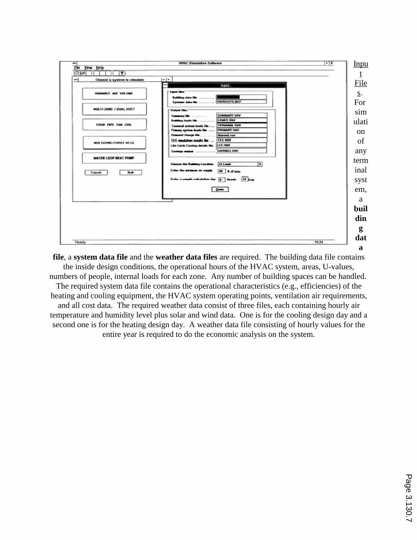
Input
Files.
For simulationof
anyterminalsystem,a
building
data
file, a system data file and the weather data files are required. The building data file containsthe inside design conditions, the operational hours of the HVAC system, areas, U-values,
numbers of people, internal loads for each zone. Any number of building spaces can be handled. The required system data file contains the operational characteristics (e.g., efficiencies) of the
heating and cooling equipment, the HVAC system operating points, ventilation air requirements,and all cost data. The required weather data consist of three files, each containing hourly air
temperature and humidity level plus solar and wind data. One is for the cooling design day and asecond one is for the heating design day. A weather data file consisting of hourly values for the
entire year is required to do the economic analysis on the system.
Page 3.130.7

Fig. 4 - Input dialog boxes.
Output Files. Each system simulation generates six output files: LOADS, PRIMARY,TERMINAL, SAVINGS, DEMAND, and SUMMARY. The LOADS file gives the hourly
values of the building loads for a sample calculation day specified by the user. It also contain annual total values of building cooling need, heating need and the dehumidification need. The
PRIMARY file contains the hourly values of primary system loads for a sample calculation day. Also the annual chiller energy, supplementary heating energy, heat rejected and the fan energy
are printed in this file. All these values are printed for each option of energy saving that ischosen by the user. The TERMINAL file contains the sizing information for the system
simulated. It has the zonal requirements for the supply air and the minimum outside air. Thehourly terminal loads for a sample calculation day for all the energy saving options that are
selected are printed in this file. Also it has the annual total values of terminal cooling energy,preheating energy, reheating energy and the fan energy for each of the options. The SAVINGS
file has the annual energy estimates for different energy saving options. Also, it has tablesshowing the savings in annual energy and percent savings with respect to base case for all those
options. The economic analysis done on these options is also printed in this file. The DEMANDfile contain the peak load, energy, demand charge, energy charge and total charge for each
month. These values are printed for each energy saving option that is selected. The SUMMARYfile prints the location of the building, the terminal system that is used and the design and
operating conditions for the system. The internal load, hours of operation, building parameters and various energy saving options are also printed in this file. Annual energy use and maximum
demand can also be obtained from this file. This file contains the equipment sizes (chiller,boiler, and fan) for the various options. It also has the percent savings and the life cost parameter
for the energy saving options. With this file it is very easy to compare various systems atdifferent locations.
SAMPLE RESULTS
The main goal has been to provide a convenient mechanism for comparing the various energysaving options for common types of terminal systems including: VAV with reheat, dual duct,
four pipe fan coil, triple deck multizone, and the closed water loop heat pump. One sample set ofruns was made to compare different terminal systems at one location. Additional sets of runs
were made to compare one terminal system with various energy saving options at four differentlocations. Locations chosen are St. Louis (moderate), Minneapolis (cold), Phoenix (hot and dry)
and Houston (hot and humid ). Page 3.130.8
All these runs are compared using the annual energy consumption (kWh /ft2) and percent savingsin annual energy. Total annual HVAC energy (kWh) was divided with total floor area (ft2) to
make annual energy consumption independent of building size. Chiller size parameter (ft2/ton)and unit boiler size (Btuh/ft3) are also compared. For comparing the chiller size parameter, totalarea (ft2) was divided by chiller capacity (tons) and total capacity of the boiler was divided bythe volume of the building to get the unit boiler size. As the chiller size (tons) increases, the
chiller size parameter (ft2 /ton) decreases and vice versa.
Comparison of Different HVAC Systems at One Location
Figure 5 shows annual energy consumption (kWh/ft2) and percent savings in annual energy forvarious terminal systems at St. Louis. It can be seen that the triple deck multizone system is thebest system at St. Louis when used in combination with the air side economizer and heat reclaimwith heat reclaim priority ( Option 4). Also, Option 4 is the best energy saving option for all the
systems except the four pipe fan coil system where the air side economizer (Option 1) is best.
Figures 6 and 7 show the chiller size parameter (ft2/ton) and unit boiler size (Btuh /ft3) for allsystems at St. Louis. It can be seen that the four pipe fan coil system with an air - to - air energy
recovery system has the lowest chiller and boiler size. For the four pipe fan coil, maximumcooling load and maximum heating load are less than that of the other systems. Air is first
cooled, even in zones requiring heating with the VAV with reheat system and, hence, chiller sizefor this is more than four pipe fan coil. The boiler size reduces for Options 2 and 4 because in
this option heat is reclaimed. In the dual duct system mixing of cold air and hot air takes place,which increases the chiller and boiler size. In the triple deck multizone , hot/cold air is mixedwith return air which reduces the chiller and boiler size as compared to the dual duct system.
Comparison of One System in Different Locations
Geographical location greatly effects the performance of energy savings options for variousterminal systems. Annual energy (kWh/ft2) and percentage savings graphs are again used to
compare a terminal system at St. Louis, Minneapolis, Houston and Phoenix. The base case (withno energy saving options) is first compared for these locations.
In Figure 8, the VAV with reheat system is compared at four locations. For the base case,annual energy consumption is maximum at Minneapolis. This is expected because Minneapolishas an extremely cold climate with high heating load. Combination of the air side economizerand heat reclaim with heat reclaim priority (Option 4) is the best energy saving option at all fourlocations. This option saves about 48 % of annual energy savings in Minneapolis and St. Louis
but for Houston this saving reduces to 30 %. This is because more heating is required atMinneapolis and St. Louis as compared to Houston and heat reclaim operation reduces the
heating load.
Effects of Thermal (Hot) Storage with Heat Reclaim and Economizer Page 3.130.9

Hot storage is a simple and effective way of both reducing equipment size and conservingenergy. Heat rejected at the condenser is used to heat a large storage tank of water. Hot storage
was included along with heat reclaim and the air side economizer for the VAV with reheatsystem in St. Louis, to study the effect of hot storage on annual energy consumption. In the VAV
with reheat system when hot storage was used along with heat reclaim and air side economizerwith priority given to heat reclaim, savings in cooling energy was observed. This is due to the
fact that when hot storage was available, the economizer was able to operate more often withoutreducing the effect of heat reclaim. It can be seen from Table I that percentage savings obtainedwith hot storage are not much for the VAV with reheat system in St. Louis. The savings of 0.1%
does not justify the additional cost of heat storage.
Table I. Savings when hot storage is used with heat reclaim and economizer with heat reclaim priority for VAV with reheat system at St. Louis
Hot storage( number of days)
Annual CoolingSavings ( kWh)
Annual HVAC Savings ( kWh)
Percentage savings inHVAC energy (%)
0 85909 577075 48
1 86390 577556 48.1
2 86390 577556 48.1
Combination of Heat Reclaim, Hot Storage, Air-to-Air Energy Recovery, and Economizer
Hot storage (1 day storage) is examined in combination with heat reclaim, air-to-air energyrecovery system (sensible effectiveness = 70 % and latent = 50 % ) and an air-side economizer. Priority is given to heat reclaim operation. This is done for the VAV with reheat system in St.
Louis. Table II shows the effect of the combination. This combination is compared with Option4 (combination of air side economizer and heat reclaim with heat reclaim priority). Savingsincrease by 1.2% when hot storage and air - to - air energy recovery is included. Again the
increase is not much and may not justify the additional cost of hot storage and air-to-air energyrecovery equipment. However, a reduction in chiller size is another benefit of the addition of air-
to-air energy recovery.
Page 3.130.10

Fig.5 -
Annual energy usage & savings for various systems & options - St. Louis.
Page 3.130.11

Fig. 6 - Variation in chiller size parameter - St. Louis.
Fig. 7 - Variation in boiler size - St. Louis. Page 3.130.12

Fig. 8 - Annual energy usage & savings for VAV system at different locations.
Page 3.130.13

Table II. Performance with economizer, heat reclaim, hot storage, and air-to-air energy recovery for VAV with reheat system in St. Louis
Option Chiller (ft2/tons)
HeatingEnergy (kWh)
CoolingEnergy (kWh)
% savings
economizer and heatreclaim 249 40110 442748 48
economizer and heatreclaim with hot storageand air - to - airenergy recovery
284 40110 427578 49.2
CONCLUDING COMMENTS
The software developed under this project should prove useful in engineering courses whichinclude the concepts of energy conservation, particularly in building systems. The programrequires minimum input and yet the results from the simulation of an actual 16-zone office
building in St. Louis, Missouri, compare quite favorably with actual utility company data [2].
From the example data presented in this paper, comparative results for the energy usage ofvarious HVAC system types and energy conserving equipment are obtainable, Specific examples
of the types of conclusions that users would obtain are:
� Performance of energy saving options depend upon the terminal system used. This can be seenfrom the fact that the combination of economizer and heat reclaim with heat reclaim priority
gives maximum savings for the VAV with reheat, dual duct, and triple deck multizone systems. When the four pipe fan coil system is used, the air side economizer gives the maximum savings.
�Geographical location also greatly affects the performance of energy saving options. Forexample, the water side economizer is least effective in Houston but at Phoenix it is most
effective. This is due to the fact that more free cooling hours are obtained in Phoenix than inHouston.
�The air side economizer does not save energy in dual duct and triple deck system if cold outsideair is allowed to go to both the cold deck and the hot deck. Heating energy increases when moreoutside air is taken for free cooling. The increase in heating energy is more than the decrease in
cooling energy. {Note: A recent article by Liu, Claridge, and Park [3] discusses the problem anda solution.}
The methodology (and corresponding software) allows exploring the interactions of various
conservation methods and selecting the appropriate equipment based on life cycle costs with anaccuracy that should make it a useful tool for design engineers as well as the engineering student.
REFERENCES
Page 3.130.14

1ANANTAPANTULA, SURYA, 1993, “Air Conditioning System Performance with Heat Reclaimand Economizer Operation,” A PhDdissertation. T 6717.
2.RAO, GURUPRASAD, 1995, “Building HVAC Energy Analysis Software Development,” An M.S. Thesis. T 7100.
3.LIU, A., D. E. CLARIDGE, AND B. Y. PARK, “An Advanced Economizer Controller for Dual Duct Air-Handling Systems - With a CaseApplication,” ASHRAE Transactions, V. 103, Pt. 2, 1997.
BIOGRAPHIES
HARRY J. SAUER, JR. is Professor of Mechanical and Aerospace Engineering at the University of Missouri-Rolla. Academic experienceincludes teaching and research in the thermal science or energetics field, with particular emphasis on heat transfer, energy conversion and
conservation, and HVAC (heating, ventilating, and air-conditioning) systems.
YOGITA GIDH has served as a Graduate Research Assistant at the University of Missouri-Rolla while working on her M.S. in MechanicalEngineering degree which she received in May 1997. Her B.E. degree in Mechanical Engineering was obtained from the University of
Bombay, India. Currently, she and her husband reside in Houston, Texas.
Page 3.130.15


![Building Performance Simulation (BPS) Software for ... · Planning of Energy Efficiency Retrofits [Sound/Visual production (digital)]. 10th Nordic Symposium on Building Physics, Lund,](https://static.fdocuments.us/doc/165x107/5f582e74d1b2ec0db52e17c5/building-performance-simulation-bps-software-for-planning-of-energy-efficiency.jpg)